1
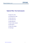
TIME LAPSE RECORDER with DIGITAL SHUTTLE
960 HR / 40 HOUR REAL TIME - COMPUTER CONTROL
User’s Guide
DV3K683DZ-SD
Be sure to read carefully and follow all the SAFETY
INFORMATION on page i.
Keep the manual in a safe place for future reference.
Worth Knowing
Please keep the video machine's guarantee card and receipt safe for warranty purposes.
Precautions
◆ Read carefully through this manual to familiarize yourself with this
high-quality Time Lapse video cassette recorder.
◆ Make sure the rating of your household electricity supply matches
that shown on the back of the Time Lapse video cassette recorder.
◆ Refer to this chapter and the "Initial installation" chapter to help you
install and adjust your Time Lapse video cassette recorder.
AUTO SET
OP EJECT
CH.
Do not ...
... expose the Time Lapse video cassette recorder to high levels of
humidity and heat, to avoid the risk of fire and electric shock.
... open the Time Lapse video cassette recorder. Have a qualified
technician carry out repairs.
... connect the Time Lapse video cassette recorder to the power supply
if you have just moved it from a cold to warm environment. This can
result in condensation inside the recorder and cause serious
damage to the machine and cassettes. Wait around two hours to
allow it to reach room temperature.
Make sure ...
... the recorder is placed on a steady, flat surface.
... you place the recorder where there is good ventilation all around.
... you clean the recorder only with a soft, lint-free cloth; do not use
aggressive or alcohol-based cleaning agents.
... you disconnect the power supply if the recorder appears to be
working incorrectly, is making an unusual sound, has a strange
smell, has smoke emitting from it or liquids have got inside it. Have
a qualified technician check the recorder.
... you disconnect the power supply and aerial if you will not be using
the recorder for a long period or during a thunderstorm.
For your own safety!
◆ There are no components in this Time Lapse video cassette
recorder you can service or repair yourself.
◆ Do not open the case of the Time Lapse video cassette
recorder. Only allow qualified personnel to repair or service
your set.
◆ This Time Lapse video cassette recorder is designed for
continuous operation. Switching it off does not disconnect it
from the mains (stand-by). To disconnect it from the mains,
you have to unplug it.
◆ Recording any copyright protected material may infringe a
copyright.
Time Lapse Video Cassette Recorder
i.
Contents
Locations of controls and indicators .............................................................................................. 1
Front panel .............................................................................................................. 1
Digital display .......................................................................................................... 2
Back panel .............................................................................................................. 4
Remote control ........................................................................................................ 5
Connections ................................................................................................................................. 6
Video Cassettes Tapes .................................................................................................................. 7
Types of On-screen displays and Display Sequence ...................................................................... 8
Setting the Clock ........................................................................................................................ 10
Changing the On-screen display ................................................................................................. 12
Normal Recording ...................................................................................................................... 14
Program Timer Recording .......................................................................................................... 16
Alarm Recording ........................................................................................................................ 20
Panic Recording ......................................................................................................................... 23
Series Recording ........................................................................................................................ 23
Autorepeat Recording ................................................................................................................ 25
Normal Playback ....................................................................................................................... 26
Normal Playback ................................................................................................... 26
Tracking Control ................................................................................................... 26
Audio Playback ...................................................................................................... 26
Special Playback ........................................................................................................................ 27
Digital Shuttle .........................................................................................................27
Reverse Play / Picture Search .................................................................................28
Still Image / Vertical Lock Control ......................................................................... 28
Recording Check / Alarm Search ........................................................................... 29
Alarm Scan / Index Search .................................................................................... 30
Other Functions .......................................................................................................................... 31
Tape counter (Zero Search) .................................................................................. 31
Setting the security Lock (Set Lock) ...................................................................... 32
Setting the HIGH PICTURE ..................................................................................... 32
Setting the SW Out Terminal Output ...................................................................... 33
RS-232C Setting ..................................................................................................... 34
Setting the buzzer .................................................................................................. 34
Checking the Alarm Recording Times .................................................................... 35
Checking Power Loss Times .................................................................................. 35
Setting In/Out Terminals ........................................................................................ 36
Daily Inspection ......................................................................................................................... 41
Troubleshooting Guide ............................................................................................................... 42
Specifications ............................................................................................................................. 44
Time Lapse Video Cassette Recorder
Locations of controls and indicators
Front panel
1
2
3
4
5
6
7
8
9
10
11
12
13
14
15
Time Lapse Video Cassette Recorder
STOP button
REC button
REC CHECK button
EJECT button
CASSETTE LOADING
DOOR
DISPLAY PANEL
PLAY button
REW button
FF button
PAUSE/STILL button
REMOTE SENSOR
HIGH-PICTURE switch
SET LOCK switch
RESET button
MENU button
16 SHIFT( ) /
TRACKING (-) button
17 SHIFT( ) /
TRACKING (+) button
18 REC/PLAY SPEED( )
button (SET - button)
19 REC/PLAY SPEED( )
button(SET + button)
20 AUDIO ON button
21 DISPLAY button
22 STANDBY/ON button
23 COUNTER button
24 CLEAR button
1
Digital Display
6
7
8
9
10
1
1
2
3
4
5
6
7
8
9
2
3
4
5
2
Operation Indicators display the actual operation
mode.
Operation Mode
Record (REC)
Record pause (REC PAUSE)
Playback (PLAY)
Still image (STILL)
Fast forward (FF)
Rewind (REW)
CUE (CUE)+
Review (REVIEW)+
Slow (Pause Still + FF, Pause Still + REW)
11
Indicator
REC
REC +
12
+
13
+
+
+
Cassette indicator :
Comes on when a cassette is loaded.
Record check indicator : REC
Flashes on during record check.
Alarm indicator :
Flashes on when an alarm is being recorded and stops
flashing after alarm recording.
Timer Recording indicator :
Comes on when in timer recording stand-by mode, or
during a timer recording.
Time Lapse Video Cassette Recorder
Power Loss indicator :
Flashes on after power loss.
CNT indicator : CNT
Comes on when the tape or alarm counter is on.
SPD indicator : SPD
Comes on when the play or recording speed is on.
HIGH PICTURE indicator : H.P
Comes on when the HIGH PICTURE sw is set to the “ON”
position.
S.REC indicator : S.REC
Comes on when “YES” is selected in the menu for the
series recording.
R.REC indicator : R.REC
Comes on when “YES” is selected in the menu for the
repeat recording.
SET LOCK SW indicator :
Comes on when the SET LOCK sw is set to the “ON”
position.
Mode display
• TAPE COUNTER display (eg:10:HOUR,59:MINUTE)
- Maximum Hour : 19 - Maximum Minute : 59
• ALARM COUNTER display (eg: A:Alarm , 32:Alarm No.)
• PLAY/REC SPEED display (eg: 30H:Play/Recording
Speed)
• TIME display (eg: 7:HOUR , 07:MINUTE)
• ERROR display (eg: E:Error , 04:Error No.)
- E-01 : The cassette cannot be loaded or unloaded.
- E-02 : The tape stops.
- E-03 : The drum can not rotate properly.
- E-04 : The tape is cut/broken.
• AUDIO ON display (eg: A:Audio , 18H:Play Speed)
Time Lapse Video Cassette Recorder
3
Back Panel
1
2
3
4
5
6
7
8
9
10
11
12
13
14
15
16
17
4
Remote Control
AC POWER CORD
WARNING OUT terminal
SERIES IN terminal
COM terminal
SERIES OUT terminal
SW OUT terminal
VIDEO OUT jack
VIDEO IN jack
AUDIO IN jack
TAPE END terminal
PANIC IN terminal
COM terminal
ALARM OUT terminal
ALARM IN terminal
MIC(microphone input) jack
AUDIO OUT jack
RS-232C jack
Time Lapse Video Cassette Recorder
20
21
22
23
24
25
Time Lapse Video Cassette Recorder
1 POWER button
2 PLAY/STILL TRACKING + button
3 PLAY/STILL TRACKING - button
4 DIGITAL SHUTTLE + button
5 DIGITAL SHUTTLE - button
6 PLAY
button
7 FF
button
8 STOP
button
9 EJECT button
10 REC/PLAY SPEED button
11 SHIFT button
12 SHIFT button
13 SET + button
14 SET - button
15 DISPLAY button
16 COUNTER button
17 CLEAR button
18 PAUSE/STILL button
19 REW
button
AUDIO ON button
REVERSE PLAY button
REC button
REC/PLAY SPEED button
REC CHECK button
MENU button
5
Connections
Video Cassettes Tapes
Connect the video camera and monitor TV as shown in
the figure below.
NOTE : Make sure to turn the power off on all devices
before making the connections.
Use only video cassette tapes bearing the
logo.
This VCR was primarily designed for use with E-180
cassette tapes. It is recommended to use E-180 VHS or E240 VHS video cassette tapes for optimal performance.
✔
• If you try to record on a
cassette without the erasureprevention tab, the VCR will
eject the cassette.
• If the TIMER button is
pressed when a cassette
without the erasureprevention tab is loaded,
the VCR will eject the
cassette, the timer recording
indicator ( ) will start
flashing and a buzzer will
sound if “YES” is set in the
menu for buzzer.
✔
• When the cassette is
loaded, the cassette
indicator “
“ will light
on the display panel.
• The counter display will
switch to the reset counter
“0H 00M 00S” display on
the monitor screen. (“0H
00M” on the display
panel.)
Power Cord Installation
✔
Insert the plug of the power cord into an outlet.
• For more details, please refer to the manuals
accompanying all other devices. If the connections are not made
properly, it may cause a fire or damage the equipment.
• For
RS-232C connection with computer and
its operation, refer to the additional RS-232C serial
communication manual.
6
Time Lapse Video Cassette Recorder
• Do not insert any object in
the cassette loading slot, as
that may cause injury and
damage to the VCR.
• If your hand gets stuck in
the cassette loading slot,
unplug the power cord and
consult the dealer where the
unit was bought. Do not
forcibly pull the hand out as
that may cause severe
injuries.
Handling Cassette Tapes
Cassette tapes should always be stored vertically in their
cases, away from high temperatures, magnetic fields,
direct sunlight, dirt, dust and locations subject to mold
formation.
Do not tamper with the cassette mechanism.
Never touch the tape with your fingers.
Protect cassette tapes from shocks or strong vibrations.
To Protect your recordings
After having recorded a tape, if you wish to keep the
recording, use a flathead screwdriver to break off the
erasure-prevention tab on the cassette.
To record again on a tape without erasure-prevention tab,
cover the hole with adhesive tape.
Erasure-prevention tab
To prevent accidental erasure, remove the
tab after recording.
To record again, cover the hole with vinyl
tape.
Loading
Place the cassette, label
side up, in the loading
slot. Gently push the
center of the cassette
until it is loaded
automatically.
Unloading
In STOP mode, press the EJECT button. The cassette is
automatically ejected.
Time Lapse Video Cassette Recorder
7
Types of On-screen displays and Display Sequence
• If the VCR is in timer recording stand-by mode (the “ ” indicator is displayed on
the display panel), the on-screen displays will not be available. First press the
POWER(STANDBY/ON) button, to cancel the recording stand-by mode, then proceed
with the VCR programming. When finished, press the POWER(STANDBY/ON) button
again to return the VCR to timer recording stand-by mode.
• When a menu is displayed, recording will not be possible.
• Press the MENU button three times, the setting procedure is now completed and the
normal screen is displayed.
• During recording or playback the menus cannot be displayed.
A
• Press the MENU button. (First time)
• Press the SHIFT button to move the arrow mark ( ) downward for the
desired item.
• Press the SHIFT button to select the desired item, then the desired menu is
displayed.
• Press the MENU button to return to the normal screen from the initial menu.
B
• Press the SHIFT button to select the desired item.
• Press the SET - (or +) button to set or Press the SHIFT
“YES” or “NO”.
• Press the MENU button to return to the initial menu.
C
• Press the SHIFT
(or SHIFT )button to select the desired item.
• Press the SET - (or +) button to set or Press the SHIFT button to select.
• Press the MENU button to return to the previous menu.
A
button to select
B
C
8
Time Lapse Video Cassette Recorder
Time Lapse Video Cassette Recorder
9
Setting the Clock
Example: To set the clock to April 12, 2001 at 9:30
Clock Setting
1
2
3
10
Turn the power on to all devices used.
Press the MENU button, the initial MENU is displayed.
The arrow mark ( ) is located in “VCR Mode Set”.
Initial MENU
Press the SHIFT button, the VCR MODE SET menu
is displayed. The arrow mark ( ) is located in
“Clock Set”.
4
Press the SHIFT
displayed.
5
Press the SET - (or +) button to set the hours (eg :
09), then press the SHIFT button.
6
Press the SET - (or +) button to set the minutes (eg
: 30), then press the SHIFT button.
7 The seconds are already set to “00”.
8 Press the SHIFT button.
9 Press the SET - (or +) button to set the month (eg :
04), then press the SHIFT button.
10 Press the SET - (or +) button to set the day (eg :
12), then press the SHIFT button.
11 Press the SET - (or +) button to set the year (eg : 01
for 2001).
• The last 2 digits only are displayed.
• The day of the week is set automatically.
12 Press the MENU button three times, the normal
screen is displayed.
• The setting procedure is now complete.
button, the CLOCK SET menu is
Time Lapse Video Cassette Recorder
Time Lapse Video Cassette Recorder
11
Changing the On-Screen Display
Selecting the On-screen Display
You can select whether or not to display the time, date,
frame counter, alarm counter, counter title.
1 Turn the power on to all devices used.
2 Press the MENU button. The initial MENU is
displayed. The arrow mark ( ) is located in “VCR
Mode Set”.
Initial MENU
✔
6
• The items for which “YES”
is set are recorded. The
items for which “NO” is
set at step 6 above are
not recorded.
Press the SET - (or +) button to set “YES” for the
functions described below.
Time................The time is displayed.
Date ................The Month-Day-Year is displayed.
Frame Cnt .......The number of frames is displayed.
Alarm Cnt ........The number of alarms is displayed.
Counter ...........The counter is displayed.
Title.................The title is displayed.
• A maximum of 20 characters can be used. (letters,
numbers or spaces)
7
8
3
Press the SHIFT button to select the VCR Mode
Set, then the VCR MODE SET menu is displayed.
Press the SHIFT button to set the display position.
Press the SET - (or +) button to set the position of
the time, date, frame cnt. alarm cnt. to “L-Bottom
(or R-Bottom)”.
• If any of 4 items is set, the position of 4 items is
changed identically.
9
4
5
12
Press the SHIFT button, until the arrow mark
( ) points “Display set”.
Press the SHIFT button to select Display Set, then
the DISPLAY SET menu is displayed.
Time Lapse Video Cassette Recorder
Press the SET - (or +) button to set the position of
the counter and title to “C-Top” (or “R-Top” or “LTop”).
If one of 2 items is set, the position of 2 items is
changed identically.
L-Top / C-Top / R-Top
: Left Top / Center Top / Right Top
L-Bottom / R-Bottom
: Left Bottom / Right Bottom
10 Press the MENU button three times, the normal
screen is displayed.
The setting procedure is now complete.
Time Lapse Video Cassette Recorder
13
Normal Recording
✔
• If the Repeat Rec Set is set
to “NO” in the REC
MODE SET menu ,
recording will continue to
the end of the tape, then
stop and the tape will be
ejected.
Normal Recording
✔
Record Pause
1
2
• During pause, the image
appears on screen but it is
not recorded.
Recording can be interrupted temporarily.
1 Press the PAUSE/STILL button during recording.
3
✔
• The recording speed is displayed on-screen and on the
display panel.
• If you don’t want to record the recording speed,
counter, title, time, date etc, press the DISPLAY button,
then start recording.
• A tape recorded on this
VCR cannot be played
back on another make of
time lapse VCR.
• If you press on the REC
button and the loaded
cassette has no erasureprevention tab, the VCR
will eject the cassette.
• During recording, the
Menu button will not
function (the menu cannot
be accessed).
✔
• If you playback the
recorded part where
recording check was
performed, noise may
appear.
• If you change the
recording speed during
recording, noise or
missing signal may result.
Turn the power on to all devices used.
Load a cassette tape with erasure prevention tab in
place.
Press the REC/PLAY SPEED (or ) button to set
the recording speed.
4
• If a recording pause
continues for 5 minutes or
more, the VCR will go into
stop mode to avoid
damage to the tape.
• The “REC” and “
display panel.
” indicators are displayed on the
2
To resume recording, press the REC button, or press
the PAUSE/STILL button again.
Time Lapse Video Cassette Recorder
15
Press the REC button.
• The “REC” indicator is displayed on the display panel
and recording starts.
5
To stop recording, press the STOP button.
<Recording Speed>
Recording Recording Recording Rec. Audio
Fields Record- Tape Motion
Speeds & Duration
Intervals
Duration E-180
/ Sec. ing
3(SP)
6(LP)
18(LP)
30(LP)
48(SP)
72(SP)
168(SP)
240(SP)
480(SP)
720(SP)
960(SP)
3
6
18
30
48
72
168
240
480
720
960
1/50 Sec
1/50 Sec
3/50 Sec
5/50 Sec
16/50 Sec
0.48
1.12
1.6
3.2
4.8
6.4
50
50
YES
16.67
10
3.13
2.08
0.89
0.62 NO
0.31
0.20
0.15
Continuous
Intermittent
✎ (SP) means to be recorded by SP heads.
(EP) means to be recorded by EP heads.
14
Time Lapse Video Cassette Recorder
Program Timer Recording
There are two program timer recording methods, daily
recording or recording on certain days of multiple weeks
(weekly recording).
Example 1 : To record on every Thursday from 10 : 00 to
18 : 00 , in 18-hour mode (recording speed)
1
2
3
Make sure that the set date and time are correct.
Load a cassette tape with erasure prevention tab in
place.
Press the MENU, SHIFT , SHIFT , SHIFT
buttons in sequence to display the TIMER PROGRAM
SET(1) menu.
✔
• If the set stop time is
earlier than or the same
time as the set start time,
the VCR will consider the
stop time to be the
following day.
9
Press the SET - (or +) button to set the recording
stop minutes (eg : 00), then press the SHIFT
button.
10 Press the SET - (or +) button to select the recording
speed (eg : 18), then press the SHIFT button.
• The cursor is moved to the N/Y position.
11 Press the SET - (or +) button to select “Y”.
Y . . . . . recording will take place
N . . . . . recording will not take place
Programmed timer recording Example 1
• Repeat steps 4 to 11 to program timer recordings for
other days of the week.
• To set two or more timer recordings the same day of
the week, press the SHIFT
button, until the cursor
located in the day of the week for the second recording,
then press the SET - (or +) button, to set the desired
day of the week. With each press of the SET - ( or +)
button, the day will change as indicated below.
• The white block cursor is on “SUN”(Sunday).
4
5
Press the SHIFT button, until the cursor is on “THU”.
Press the SHIFT button.
• The cursor is moved to the recording start hour position.
6
Press the SET - (or +) button to set the recording
start hour (eg : 10), then press the SHIFT button.
SET - :
direction , SET + :
direction
• The cursor is moved to the recording start minutes
position.
7
Press the SET - (or +) button to set the recording
start minute (eg : 00), then the SHIFT button.
• The cursor is moved to the recording stop hour position.
8
Press the SET - (or +) button to set the recording
stop hour (eg : 18), then press the SHIFT button.
• The cursor is moved to the recording stop minutes
position.
16
Time Lapse Video Cassette Recorder
✔
• To modify or cancel timer
recording, press the
POWER(STANDBY/ON)
button to cancel the timer
recording mode.
12 Press the MENU button three times, the normal
screen is displayed.
13 Press the POWER(STANDBY/ON) button.
• The timer recording indicator “ ”will light on the
Time Lapse Video Cassette Recorder
display panel. The VCR is now in timer recording
stand-by mode.
17
Example 2 : To record everyday from 10 : 00 to 18 :
00, in 18-hour mode (recording speed)
1
2
Repeat steps 1 to 3.
Press the SHIFT button, until the cursor is on
“DLY”. The MENU below is displayed.
To Cancel a Program Timer Recording
1
2
3
4
5
3
Repeat step 1 above.
Press the SHIFT (or ) button until the cursor is
located in the “Y” corresponding to the timer
recording to cancel.
Press the SET - (or +) button, to select “N”.
Press the MENU button three times until the normal
screen is displayed.
Press the POWER(STANDBY/ON) button.
• The clear button can erase the programmed timer
recording in the line that the cursor is located.
Repeat steps 5 to 13.
Programmed timer recording Example 2
Notes...
• During timer recording all the buttons on the VCR, except
the STOP button, are disabled. If the STOP button is
pressed for three seconds during timer recording, the
recording will stop. During timer recording stand-by,
press the POWER(STANDBY/ON) button if the buttons do
not respond.
• If there is a power loss, the recording will be interrupted.
When the power is restored, the recording will resume if
the stop time has not yet been reached, and “ ” will be
flashing on the display panel. The VCR internal battery is
completely charged after the VCR has been connected to
an AC power outlet for 48 hours, and it will maintain all
the VCR settings memory for up to 30 days.
• Set the timer recordings so that the recording times do
not overlap. If they do, the one with the earliest recording
start time will have priority.
(See chart below)
Changing a Program Timer Recording
1
2
3
Press the MENU, SHIFT , SHIFT , SHIFT
buttons in sequence to display the TIMER PROGRAM
SET(1) menu.
Press the SHIFT (or ) button, until the cursor
is located in the setting to correct.
Press the SET - (or +) button, to correct the setting.
• Press the MENU button three times until the normal
screen is displayed.
4
Press the POWER(STANDBY/ON) button.
• If the cassette tape is ejected while timer recording is set,
the buzzer will be heard 5 times (when the buzzer
function is set to “YES”.)
18
Time Lapse Video Cassette Recorder
Time Lapse Video Cassette Recorder
19
Alarm Recording
• Auto / 20sec / 30sec / 40sec / 01min / 02min / 3min /
5min / 10min / 15min / 20min / 25min / 30min :
Recording for the set duration. (min : minute)
• T.END : Records until the tape end is reached when
there is alarm trigger input.
Alarm Recording Setting
Alarm recording is performed when there is an input
(trigger) at the ALARM IN terminal, “ ” is displayed
on the display panel.
1 Make all necessary connections.
2 Press the MENU, SHIFT , SHIFT buttons in
sequence to display the REC MODE SET menu .
3 Press the SHIFT button until the arrow mark ( )
points to ALARM REC SET.
4 Press the SHIFT button to display the ALARM REC
SET menu.
✔
Alarm Recording Counter Display
• Alarm Counter Reset can
be performed by pressing
the CLEAR key in “Alarm
Time” of Initial Menu
screen.
During alarm recording, “ ” will be flashing on the
display panel.
The maximum display number of alarm triggers is “35”,
at the next alarm recording the counter will indicate
“00”.
Connecting to a Monitor for Normal Recording
✔
• During alarm recording all
buttons are disabled
except the STOP button. If
the STOP button is
pressed, the alarm
recording will stop.
5
• If an alarm trigger is
received while alarm
recording is in progress,
the recording duration for
the second alarm will be
calculated from that point.
6
7
• When there is a power
loss during alarm
recording, if the power is
restored within the
recording set duration,
alarm recording will
continue.
• When you select ‘Alarm
Duration’ as 20sec,
30sec, 40sec or 1min,
alarm search error may
happen. Therefore confirm
it in ‘Alarm TIme’ menu
and scan it.
20
Press the SHIFT
button to select “YES” or “NO”.
• YES . . . .The alarm recording takes place when there is
alarm trigger input
• NO . . . . The alarm recording does not take place
Press the SHIFT button to set the Alarm speed.
Press the SHIFT button to select the desired
recording speed.
•
•
•
•
8
9
3H . . . 3-hour mode recording
6H . . . 6-hour mode recording
18H . . 18-hour mode recording
30H . . 30-hour mode recording
Press the SHIFT button to set the alarm duration.
Press the SHIFT button to select the desired
recording duration.
• Auto : Records as long as the alarm signal is being
input. (Minimum 2 minutes is recorded.)
Time Lapse Video Cassette Recorder
Time Lapse Video Cassette Recorder
21
Panic Recording
This feature is similar to an alarm recording, but the
recording time is not pre-selected.
When there is a panic input at the PANIC IN Terminal,
recording will start and continue for up to 3 hours.
Connecting to a Monitor for Alarm Recording
Series Recording
Using 2 VCRs or more, the series recording function lets
you switch recording from one unit to the next (only
with VCRs of the same model as this one).
Series Recording Setup
1
2
✔
• During series recording,
autorepeat recording or
timer recording are not
possible.
• If in the REC MODE SET
menu, “Series Rec Set” is
set to “NO”, series
recording will not be
possible.
Connect 2 VCRs or more as illustrated on next page.
Set the following items as indicated.
Item
VCR No.2
and on
Cassette tape
Loaded
Loaded
Operation mode
Stop
Stop
Repeat Rec Set
“NO”
“NO”
Series Rec Set
“YES”
“YES”
Timer recording
OFF (not set) OFF (not set)
Security lock switch (SET LOCK switch) “OFF”
“ON”
3
VCR No.1
Press the REC button on VCR No.1.
• Recording will start in series recording mode.
22
Time Lapse Video Cassette Recorder
Time Lapse Video Cassette Recorder
23
Autorepeat Recording
4
Set the security lock on VCR No.1.
Autorepeat Recording
• When the end of the tape on VCR No.1 is reached, the
output at the SERIES OUT terminal will switch signal.
This will start recording on VCR No.2, the tape will stop
and be ejected on VCR No.1.
The same tape can be recorded over many times. Please
note that if you activate this feature you will lose the
entire previous recording.
1 Press the MENU, SHIFT , SHIFT button in
sequence to display the REC MODE SET menu.
✔
• If during autorepeat
recording there is an
alarm trigger, “
“ is
displayed on the display
panel and alarm
recording will take place.
Autorepeat recording will
continue after alarm
recording has completed
its programmed duration.
2
3
Press the SHIFT button to make the arrow mark
( ) point to Repeat Rec Set.
Press the SHIFT button to set the desired
autorepeat recording mode.
NO . . . . . . Autorepeat recording doesn’t take place.
YES . . . . . Autorepeat recording takes place.
“R.REC” will light on the display panel.
4
Press the MENU button two times, the normal screen
is displayed.
• The setting procedure is now complete.
5
Press the REC button.
• Recording will start. When the tape’s end is reached,
the VCR will rewind it to the beginning regardless of
the counter memory, and recording will resume.
24
Time Lapse Video Cassette Recorder
Time Lapse Video Cassette Recorder
25
Normal Playback
✔
• A slow motion effect or
accelerated playback
effect can be achieved by
using a slower or faster
playback speed than the
speed used for recording.
Special Playback
Normal Playback
Digital Shuttle
1
2
3
1
Turn on the power to the TV monitor.
Load the video cassette tape.
Press the REC/PLAY SPEED (or ) button to
select the playback speed.
• The selected playback speed is displayed on the display panel.
• A tape recorded with LP heads can be played in 6-hour,
18-hour, 30-hour, 48-hour .... or 960-hour modes.
• A tape recorded with SP heads can be played in 3-hour,
12-hour, 24 -hour, 48-hour .... or 960-hour modes.
• The picture quality recorded by LP heads can be lower
than SP heads.
4
Press the PLAY button.
• Playback starts.
5
To stop playback, press the STOP button.
• To advanced or rewind the tape, press the FF/CUE or
REW/REVIEW button.
✔
• If playback image isn’t
clear, adjust the screen by
pressing TRACKING+/button.
Tracking Control
1
2
3
✔
• Noise will appear in the
image when audio
playback is used in 18hour or 30-hour mode.
26
To use this function with remote control
• Press DIGITAL SHUTTLE +/- button on remote
control in playback mode to enter into Digital
Shuttle function.
• Shuttle speed will change as follows :
While looking at the playback picture, press and
hold the TRACKING + button to minimize the noise.
If it cannot be minimized, press the TRACKING button.
If there is noise in the image during playback, push
the ‘pause’ button. Then, while looking at the paused
picture press and hold the TRACKING + or - button
until a clear stable picture is obtained.
Audio Playback
Audio playback is only possible in 3-hour, 6-hour, 18hour and 30-hour modes.
The playback speed has to be the same as the recording
speed, for normal playback of the audio.
For a tape recorded in 3-hour, 6-hour 18-hour and 30hour modes,to playback the audio, press the AUDIO ON
button after pressing the PLAY button. “A” will be
displayed to the left of the playback speed on the display
panel. Press the AUDIO ON button again to remove “A”.
Time Lapse Video Cassette Recorder
✔
• You can’t use shuttle
function in front panel
button without pressing
STILL button first.
2. To use this function with set button
• Press STILL button on front panel in playback
mode. Then press REW or FF button to enter into
Shuttle function.
• Shuttle speed will change as follows :
3. To return to normal playback, press the PLAY button.
4. Slow & Reverse slow speed
Slow step 1 = 1/30 times
Slow step 2 = 1/15 times
Slow step 3 = 1/5 times
Reverse slow step 1 = -1/30 times
Reverse slow step 2 = -1/15 times
Reverse slow step 3 = -1/5 times
Time Lapse Video Cassette Recorder
27
✔
Reverse Play
✔
Recording Check
• The tape recorded in 48H
mode will be reverseplayback in 3H. And the
tape recorded in 18H or
30H mode will be reverseplayback in 6H.
•
• During recording check
operations, recording is
suspended momentarily.
During recording, press the REC CHECK button.
Press R.PLAY button on remote control in playback
mode to enter into Reverse Play mode.
• During reverse-playback in
3H and 48H, noise band
may appear in the picture.
And during reverseplayback in 6H, noise
may appear in upper or
bottom side of the picture.
Alarm Search
•
✔
• During picture search,
noise (horizontal bars) will
appear in the picture.
1
2
Press the Menu button to display the initial menu.
Press the SHIFT button to select Search Select,
then press the SHIFT button to display the
SEARCH SELECT menu.
3
Move the arrow mark ( ) to FF or REW in the
Alarm Search mode as you want to search.
Press the SET -(or +) button to enter the number of
alarm marks you want to search, press the SHIFT
button to search forward or in reverse.
To return to normal playback, press the PLAY button.
Picture Search
1
Press the FF/CUE (or REW/REVIEW) button, during
normal playback.
• The image can be seen while the tape is advanced (or
rewound) at high speed.
• The sound is muted.
✔
2
• If still mode continues for
5 minutes or more, the
VCR will go into stop
mode to avoid damaging
the tape.
Still Image
• If the image is unstable
(rolling vertically), adjust
the tracking control to
correct.
• The tape will be rewound for about 5 seconds and slow
play mode will be performed. The VCR will then return
to the previous recording mode.
1
To return to normal playback, press the PLAY button.
4
Press the PAUSE/STILL button, during normal
playback.
• The display returns to the normal screen.
• The VCR will locate the desired alarm recording and
begin playback.
• A still image can be viewed.
2
To return to normal playback, press the PLAY button.
• With each press of the PAUSE/STILL button, the still
image is advanced one image (frame).
Vertical Lock Control
During still image mode,
1 Press the TRACKING + button to reduce the vertical
rolling of the image.
2 If it cannot be corrected, press the TRACKING - button.
28
Time Lapse Video Cassette Recorder
Time Lapse Video Cassette Recorder
29
Other Functions
✔
Alarm Scan
1
2
Repeat steps 1 to 3.
Press the SHIFT button to search forward or in
reverse without entering a specific alarm number.
• The display returns to the normal screen.
• The VCR will advance (or rewind) the tape at high
speed, and playback the first 5 seconds of every alarm
recording.
• To cancel the alarm scan mode, press the STOP button.
3
While the desired recording is being played back,
press the PLAY button.
• Playback will start, and alarm scan is cancelled.
Index Search
1
2
✔
3
• In the index search mode,
SHIFT button should be
used to search forward or
in reverse ( Index FF /
REW).
Repeat steps 1 to 2.
Move the arrow mark ( ) to the FF or REW in the
Index Search mode as you want to search.
Press the SHIFT button to search forward or in
reverse.
• The display returns to the normal screen.
• The VCR will advance (or rewind) the tape at high
speed and playback the first 5 seconds of every normal
recording.
• To cancel the index search mode, press the STOP
button.
4
While the desired recording is being played back,
press the PLAY button.
• Playback will start, and index search is cancelled.
• When you insert a
cassette, the counter
always resets to zero.
• There is no tape counter
indication for the blank
portions of tape.
• In the 3-hour recording
speed mode only, the tape
counter indicates real
hours, minutes and
seconds.
• In the other SP recording
speed modes (48H), the
tape counter indication is
a ratio of the 3-hour mode
base indication.(In 48hour recording mode,
each “second” of the tape
counter actually represents
approximately 48/3 =
16 real seconds.)
• In the other LP recording
speed modes (18H), the
tape counter indication is
a ratio of the 6-hour mode
base indication. (In 18hour recording mode,
each “second” of the tape
counter actually represents
approximately 18/6 = 3
real seconds.)
• In the other LP recording
speed modes (30H), the
tape counter indication is
a ratio of the 6-hour mode
base indication. (In 30hour recording mode,
each “second” of the tape
counter actually represents
approximately 30/6 = 5
real seconds.)
Tape Counter (Zero Search)
Using the counter, it is easy to find a desired recording.
1 Press the CLEAR button, at the beginning of the
desired recording.
• The counter will be reset to “0H 00M 00S” (on screen).
• The counter will be reset to “0H 00M”(on the display
panel).
2
3
4
5
6
After recording or playback, press the Menu button
to display the initial MENU.
Press the SHIFT button to move the arrow mark
( ) to Search Select.
Press the SHIFT button to display the SEARCH
SELECT menu. The SEARCH SELECT menu is
displayed.
Press the SHIFT button to move the arrow mark
( ) to Zero Search.
Press the SHIFT button to search the counter “0H
00M 00S”(“0H 00M” on the display panel).
• The display returns to the normal screen.
• The tape is rewound or advanced to the counter “0H
00M 00S” reading(“0H 00M” on the display panel).
• There may be a slight
discrepancy between the
position shown on the
tape counter and the
actual tape position.
• When rewinding the tape
past the “0H 00M 00S”
position(“0H 00M” on the
display panel), a minus(-)
displayed.
30
Time Lapse Video Cassette Recorder
Time Lapse Video Cassette Recorder
31
Setting the Security Lock (Set Lock)
Setting the SW Out Terminal Output
• While the security lock is
engaged, all commands
are disabled.
The security lock function is designed to prevent
accidental stopping of recording if the STOP button is
pressed inadvertently.
1 Set the SET LOCK switch to “ON” position.
• The security lock should
not be engaged while a
menu is displayed.
2
Synchronization pulses for multiplexer can be obtained
from the SW OUT terminal.
1 Press the MENU button, to display the initial MENU.
2 Press the SHIFT button to move the arrow mark
( ) to SW OUT Terminal Set.
3 Press the SHIFT button to display the SW OUT
TERMINAL SET menu.
✔
•“
“ is displayed on the display panel.
To cancel the security lock, set the SET LOCK switch
to “OFF” position.
•“
“ will be erased from the display panel.
Setting the HIGH PICTURE
With this function, you can view the screen in highpicture quality.
1 Set the HIGH-PICTURE switch to “ON” position.
✔
• If “TIMING” is set to
FRAME (see step 6),
“FRAME” will be indicated
instead of “FIELD”.
• In case of TimeLapse
mode, refer to the
“Recording Speed” Table
of page 14.
4
• “ H.P” is displayed on the display panel.
2
To cancel the HIGH-PICTURE function, set the HIGHPICTURE switch to “OFF” position.
• “ H.P” is disappeared from the display panel.
Press the SHIFT
“FRAME”).
button to set “FIELD” (or
• With each press of the SHIFT
change as indicated below.
5
6
Press the SHIFT
Press the SHIFT
button, the setting will
button, to select Timing.
button to set the “TIMING”.
• AUTO . . . When you connect with external equipment,
the field will be switched automatically.
• FIELD . . . 1 pulse is output after each set number of
fields. (VHS mode, 3H, 6H)
• FRAME . . 1 pulse is output after each set number frames.
(VHS mode, 3H, 6H)
7
Press the MENU button, the normal screen is
displayed.
• The setting procedure is now complete.
32
Time Lapse Video Cassette Recorder
Time Lapse Video Cassette Recorder
33
✔
RS-232C Setting
Checking the Alarm Recording Times
• For RS-232C connection
with computer and its
operation, refer to the
additional RS-232C serial
communication manual.
You can control this set in remote by communication
with Computer.
• Communication speed : 19200bps
9600bps
4800bps
1
2
✔
Setting the Buzzer
In the following cases, the
buzzer will be heard
approximately 5 times.
1
2
- If the REC button is pressed
while a cassette without
erasure-prevention tab is
loaded.
✔
• The data for the previous
alarm recordings, past
35, is erased.
Press the MENU button to display the initial MENU.
Press the SHIFT button to select VCR Mode Set.
The VCR MODE SET menu is displayed.
- If the TIMER button is
pressed without inserting a
cassette.
• The number of alarm triggers and the 35 most recent
alarm recording times are displayed.
4
Press the MENU button twice, the normal screen is
displayed.
Checking Power Loss Times
- If a cassette, without the
erasure - prevention tab, is
loaded while the timer is
set.
- If there is a series recording
input while a cassette
without erasure-prevention
tab is loaded.
3
Press the MENU button to display the initial MENU.
Press the SHIFT button to move the arrow mark
( ) to Alarm Time.
Press the SHIFT button to display the ALARM
TIME menu.
1
2
3
4
Press the SHIFT button to move the arrow mark
( ) to Buzzer Set.
Press the SHIFT button to set “YES” for the
functions described below.
• The buzzer will be heard whenever a button is pressed.
✔
• POWER LOSS ....
3
the number of power
losses and the date and
time of the 35 most recent
power losses and
recoveries are displayed.
Press the MENU button to display the initial MENU.
Press the SHIFT button to move the arrow mark
( ) to Power Loss Time.
Press the SHIFT button to display the POWER
LOSS TIME menu.
• The number of power losses, and the 35 most recent
power loss times are displayed.
✔
• If “NO” is set, the buzzer
will not operate.
4
34
Time Lapse Video Cassette Recorder
Time Lapse Video Cassette Recorder
Press the MENU button twice, the normal screen is
displayed.
35
Setting In/Out terminals
1
2
3
4
5
6
7
36
Press the MENU button to display the initial MENU.
Press the SHIFT button to display the VCR MODE
SET menu.
Press the SHIFT button to move the arrow mark
( ) to In/Output Set.
Press the SHIFT button to display the IN/OUTPUT
SET menu.
Press the SHIFT button to move the arrow mark
( ) for the desired item.
Press the SHIFT button to set “N/C” or “N/O”,
“High” or “Low”.
Press the MENU button three times, the normal
screen is displayed.
Time Lapse Video Cassette Recorder
• ALARM INPUT Terminal
This terminal is to connect PIR sensors, door contacts or
any type of motion detector.
1) “N/C” (Normally CLOSED Switch Circuit)
If the input becomes DC 5V for 500 msec or more,
the VCR starts alarm recording.
2) “N/O” (Normally OPEN Switch Circuit)
If the input becomes 0V for 500 msec or more, the
VCR starts alarm recording.
• ALARM OUTPUT Terminal
This terminal is to connect to any external source, such
as a siren, etc.
1) “High”
When an alarm input is received and the unit is
recording, the output becomes DC 5V. Once the
alarm recording is over, the output returns to 0V.
2) “Low”
When an alarm input is received and the unit is
recording, the output becomes 0V. Once the alarm
recording is over, the output returns to DC 5V.
• PANIC INPUT Terminal
1) “N/C” (Normally CLOSED Switch Circuit)
If the input becomes DC 5V for 500 msec or more,
the VCR starts panic recording.
2) “N/O” (Normally OPEN Switch Circuit)
If the input becomes 0V for 500 msec or more, the
VCR starts panic recording.
• TAPE END(OUT) Terminal
1) “High”
During recording, when the end of the tape is
reached, the output becomes DC 5V.
2) “Low”
During recording, when the end of the tape is
reached, the output becomes DC 0V.
Time Lapse Video Cassette Recorder
37
• SW OUTPUT Terminal
While recording, a pulse signal(DC 5V) is output at the
SW OUT terminal after each recording period. This
terminal is usually connected to the switch input of
devices like a camera switching unit, or a quad
compressor.
1) Low
If you are also using a Multi View system, use the
following diagrams as a guide to connecting the VCR for
normal or alarm recording.
Connecting to a Multiview System for Normal Recording
2) High
• SERIES OUTPUT Terminal
During recording, when the end of the tape is reached,
the output becomes DC 5V .
• SERIES INPUT Terminal
If the input becomes DC 5V for 200 msec or more, the
VCR starts series recording.
• WARNING OUTPUT Terminal
1) “High”
If the error display on the display panel continues to
flash, the output becomes DC 5V. If the POWER
button is pressed, the emergency mode is released,
then the output becomes 0V.
2) “Low”
If the error display on the display panel continues to
flash, the output becomes 0V. If the POWER button is
pressed, the emergency mode is released, then the
output becomes DC 5V.
38
Time Lapse Video Cassette Recorder
Time Lapse Video Cassette Recorder
39
Daily Inspection
The following daily inspections are recommended in
order to assure long-term and trouble-free operation of
the unit.
The daily inspections are particularly important if using
autorepeat recording.
Connecting to a Multiview System for Alarm Recording
✔
• If the security lock is
engaged, it has to be
released before
proceeding with the
inspection.
• If any problem is
discovered during the
inspection,unplug the
power cord and consult
your dealer.
Inspection Procedure
1
2
3
4
5
Turn on the power to the camera, TV monitor and
other connected devices.
Check that the image received on the TV monitor is
correct.
Check that the on-screen display of the date and time
is correct.
Press the REW button to rewind the recorded tape a
few seconds.
Press the PLAY button and check that the playback
image is correct.
• Check in particular playback of time lapse recording
(18 or 30 hour mode).
6
40
Time Lapse Video Cassette Recorder
Time Lapse Video Cassette Recorder
Check that the recorded date and time are correct.
41
Troubleshooting Guide
SYMPTOM
If the unit does not operate normally when you follow the instructions indicated in
the manual, please refer to the table below.
SYMPTOM
No power.
POSSIBLE CAUSE
- Connect the power cord firmly into
the wall outlet.
- This is normal, not a malfunction.
No image
displayed on the
monitor TV.
The connections are not correct.
The power to the camera and/or
monitor TV is not turned on.
- Check that all connections are correct.
- Turn all connected devices power
on.
The buttons do
not respond.
The unit is in timer recording standby mode.
Alarm recording.
- Press the POWER(STANDBY/ON)
button.
- Wait for the alarm recording to end.
- Press the STOP button for 3 seconds
to stop.
- Wait for the panic recording to end.
- Press the STOP button for 3 seconds
to stop.
- Cancel the security lock.
Panic recording.
The security lock(SET LOCK) is
engaged.
42
Timer recording. The date and time are not correct.
The unit is not set to timer recording
stand-by mode.
“N” is selected for the TIMER
PROGRAM SET.
CORRECTIVE ACTION
The power cord is not correctly
connected to the wall outlet.
The unit is in timer recording standby mode.
Unit will not go
into record
mode.
The loaded cassette has no
erasure prevention tab.
- Load a cassette tape with
erasure prevention tab or cover the
tab hole with adhesive tape.
Autorepeat.
“NO” is selected for autorepeat
recording in the REC MODE SET
menu.
During autorepeat recording when
there is an alarm input, autorepeat
recording is canceled.
- Be sure to select “YES” for
autorepeat recording.
- Set “YES” again for autorepeat
recording.
Time Lapse Video Cassette Recorder
POSSIBLE CAUSE
CORRECTIVE ACTION
- Set the date and time correctly.
- Press the POWER(STANDBY/ON) button
to display “ ” on the display panel.
- Be sure to select “Y” for the TIMER
PROGRAM SET.
Alarm recording. “NO” is selected for alarm recording in - Be sure to select “YES” for alarm
the ALARM REC SET menu.
recording.
Noise in the
playback picture.
The tracking adjustment is in the
wrong.
The video heads need cleaning.
The date and
time are not
recorded.
“NO” is selected for the date and time - Be sure to select “YES” for the
in the DISPLAY SET menu.
display.
The date and time go off the ON-SCREEN
- Press the DISPLAY button to show the
by pressing the DISPLAY button.
date and time.
The cassette tape
cannot be ejected
Problem with the system or tape.
- Adjust it by using the manual
tracking.
- Clean the video heads.
- Unplug the power cord then plug it
back in.
Periodic Inspection and Maintenance
Periodic inspection and maintenance should be referred
to your dealer. If there is noise in the playback picture,
and it cannot be corrected using the tracking
control, it may indicate that the video heads need
cleaning. The video heads should be cleaned and
inspected every 1,000 hours. The video heads usage can
be checked using initial menu, running time.
✔
• Press the RESET button for
more than 0.5 seconds to
perform the reset. Running
Time will not be reset.
System Down
If the unit does not function at all, try the following.
1 Unplug the power cord then plug it back in.
2 Reset the memory. (Press the RESET button. Under
normal conditions, do not touch the RESET button.)
3 If the problem is not corrected after performing
steps 1 and 2, consult your dealer.
Time Lapse Video Cassette Recorder
43
Specifications
General Specifications
Recording method
Audio recording
Tape speed
Specified video cassette tape
Recording/playback time
Fast forward/rewind time
Television system
Video
Recording method
Video input
Video output
Horizontal resolution
Dual-azimuth 4-head rotating helical scanning system
In 3, 6, 18 and 30 hour modes
33.35 m/sec (3 hour mode)
VHS 1/2 inch video cassette tape
3, 6, 18, 30, 48, 72, 168, 240, 480, 720, 960 hours
(when using E-180 tape)
Within 3 minutes (when using E-180 tape)
PAL color TV system
Luminance signal : FM recording
~0.8V Down-converted subcarrier phase shift system
1 Vp-p, BNC, 75Ω, unbalanced
1 Vp-p, BNC, 75Ω, unbalanced
Black & white mode
300 lines
Color mode
250 lines
Audio
Input
Output
Microphone input
RCA pin jack more than 47kΩ -8.8dBm, unbalanced
RCA pin jack less than 1.5kΩ -7.8dBm, unbalanced
-60 dBs, 3.5mm mini jack, 10kΩ, unbalanced
Connectors
Alarm input
Alarm output
Panic input
End output
Warning output
Series input
Series output
Switch output
Common
DC 4~5V(Open), DC 0~0.8V(Closed)/5.7kΩ
DC 4~5V(H), DC 0~0.8V(L)/5.7kΩ
DC 4~5V(Open), DC 0~0.8V(Closed)/5.7kΩ
DC 4~5V(H), DC 0~0.8V(L)/5.7kΩ
DC 4~5V(H), DC 0~0.8V(L)/5.7kΩ
DC 4~5V(H), DC 0~0.8V(L)/5.7kΩ
DC 4~5V(H), DC 0~0.8V(L)/5.7kΩ
DC 4~5V(H), DC 0~0.8V(L)/5.7kΩ
0V( GND)
Other Specifications
Operating temperature range
Operating humidity range
Power requirements
Power consumption
Dimensions
Weight
41ºF - 104ºF
80% or less
AC 90-250V , 50/60 Hz
12W
360(W) x 90(H) x 289(D)
approximately 4kg
NOTE : The specifications and external appearance of this unit are subject to change
without notice.
44
Time Lapse Video Cassette Recorder