1
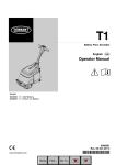
Operators Manual Serial number 000000 and after Part Number 0120843 September 2010 Table of Contents Table of Contents Declaration of Conformity............................................2 Safety Rules................................................................3 Introduction..................................................................4 Component Identification.............................................4 Special Limitations......................................................5 Platform Capacity.....................................................5 Manual Force...........................................................5 Lift Level Sensor Interlock........................................5 Lowering Alarm........................................................5 Lowering Interrupt....................................................5 Controls and Indicators...............................................6 Lower Controls............................................................6 Emergency Stop Button...........................................6 Control Selector Switch............................................6 Ground Operation Button.........................................7 Platform Raise/Lower Buttons..................................7 Battery Charger Mode Selector................................7 Upper Controls............................................................7 Emergency Stop Button...........................................7 Interlock Button........................................................7 Platform Raise/Lower Buttons..................................7 Pre-Operation Safety Inspection.................................8 System Function Inspection........................................9 Operation...................................................................10 Preparing for Operation.............................................10 Lower Controls..........................................................10 Upper Controls..........................................................10 Platform..................................................................... 11 Raising and Lowering............................................. 11 Lowering Interrupt.................................................. 11 Component Tray........................................................ 11 Emergency Lowering................................................. 11 Transporting the Machine..........................................12 Preparing for Transportation..................................12 Transporting...........................................................12 Lifting With a Forklift...............................................12 Lifting With a Tail Lift..............................................12 Maintenance..............................................................13 Hydraulic Fluid.......................................................13 Check Hydraulic Fluid............................................13 Battery Maintenance..............................................13 Battery Charging....................................................13 Inspection and Maintenance Schedule.....................14 Daily Preventative Maintenance Checklist................15 Preventative Maintenance Report..........................15 General Specifications – PUSH6..............................16 General Specifications – PUSH8..............................17 General Specifications – PUSH10............................18 PUSH6/PUSH8/PUSH10 – 0120843 EC DECLARATION OF CONFORMITY FOR MACHINERY MACHINERY: Powered Aerial Platform known as: Type: Serial Number: PUSH8-04-xxxxxx Pop Up PUSH8 The machine specified above conforms to the following provisions: Machinery directive 2006/42/EC (using document EC Community Legislation on Machinery and taking guidance from EN280:2001 + Amendment A2:2009) Council Directive 2004/108/EC on Electromagnetic Compatibility Council Directive 2006/95/EC on Low Voltage Equipment Safety Type approval in accordance with 2006/42/EC performed by: Powered Access Certification LTD P. O. Box 98, Windermere Cumbria, LA23 1WF, UK Notified Body Identification Number: 0545 E. C. Type Examination Certificate No: Authorized Representative in European Union: The Tanfield Group, PLC Vigo Centre, Birtley Road Washington, Tyne & Wear NE38 9DA, UK Note: Modification of the specified unit renders this declaration invalid. PUSH6/PUSH8/PUSH10 – 0120843 SAFETY RULES Warning All personnel shall carefully read, understand and follow all safety rules and operating instructions before operating or performing maintenance on any Pop Up aerial work platform. Electrocution Hazard Tip Over Hazard Collision Hazard Fall Hazard NEVER climb, stand, or sit NEVER position the platform NEVER elevate the platform on platform guardrails or without first checking for or drive the machine while midrail. overhead obstructions or elevated unless the machine other hazards. is on a firm, level surface. USE OF THE AERIAL WORK PLATFORM: This aerial work platform is intended to lift persons and his tools as well as the material used for the job. It is designed for repair and assembly jobs and assignments at overhead workplaces (ceilings, buildings etc.). Uses or alterations to the aerial work platform must be approved by Pop Up. THIS AERIAL WORK PLATFORM IS NOT INSULATED! For this reason it is imperative to keep a safe distance from live parts of electrical equipment! Exceeding the specified permissible maximum load is prohibited! See “Platform Capacity” on page 5 for details. The use and operation of the aerial work platform as a lifting tool or a crane is prohibited! NEVER exceed the manual force allowed for this machine. See “Manual Force” on page 5 for details. DISTRIBUTE all platform loads evenly on the platform. NEVER operate the machine without first surveying the work area for surface hazards such as holes, drop-offs, bumps, curbs, or debris; and avoiding them. OPERATE machine only on surfaces capable of supporting wheel loads. NEVER operate the machine outdoors or indoors when wind speeds exceed 0 m/s (0 mph). Do not operate the aerial platform in windy or gusty conditions. Do not add anything to or take anything into the aerial platform that will increase the wind loading such as billboards, banners, flags, etc. IN CASE OF EMERGENCY push EMERGENCY STOP switch to deactivate all powered functions. IF ALARM SOUNDS while platform is elevated, STOP, carefully lower platform. Move machine to a firm, level surface. Climbing up the railing of the platform, standing on or stepping from the platform onto buildings, steel or prefab concrete structures, etc., is prohibited! Dismantling the entry gate or other railing components is prohibited! Always make certain that the entry gate is closed! It is prohibited to keep the entry gate in an open position when the platform is raised! To extend the height or the range by placing of ladders, scaffolds or similar devices on the platform is prohibited! NEVER perform service on machine while platform is elevated without blocking elevating assembly. INSPECT the machine thoroughly for cracked welds, loose or missing hardware, hydraulic leaks, loose wire connections, and damaged cables or hoses before using. VERIFY that all labels are in place and legible before using. NEVER use a machine that is damaged, not functioning properly, or has damaged or missing labels. To bypass any safety equipment is prohibited and presents a danger for the persons on the aerial work platform and in its working range. NEVER charge batteries near sparks or open flame. Charging batteries emit explosive hydrogen gas. Modifications to the aerial work platform are prohibited or permissible only at the approval by Pop Up. AFTER USE, secure the work platform from unauthorized use by turning the keyswitch off and removing key. The driving of MEWP’s on the public highway is subject to national traffic regulations. Certain inherent risks remain in the operation of this machine despite utilizing proper design practices and safeguarding. Care must be taken to ensure that the machines meets the requirements of stability during use, transportation, assembly, dismantling when out of service, testing, or foreseeable breakdowns. In the event of an accident or breakdown see “Emergency Lowering” on page 11, do not operate the aerial platform if it is damaged or not functioning properly. Qualified maintenance personnel must correct the problem before putting the aerial platform back into service. THIS MACHINE IS NOT INSULATED! PUSH6/PUSH8/PUSH10 – 0120843 Introduction Introduction When contacting Pop Up for service or parts information, be sure to include the MODEL and SERIAL NUMBERS from the equipment nameplate. Should the nameplate be missing, the SERIAL NUMBER is also stamped on the front of the chassis. This manual covers the PUSH6, PUSH8, and PUSH10 Aerial Work Platforms. This manual must be stored on the machine at all times. Read, understand and follow all safety rules and operating instructions before attempting to operate the machine. Component Identification Upper Controls Platform Entry Gate Operators Manual Guardrails Toeboards Scissors Structure Component Tray Hydraulic Reservoir/Pump • Batteries Safety Prop One on Each Side Forklift Pocket Chassis Forklift Pocket Lower Controls Brake Lever Battery Charge Indicator Right Side Emergency Lowering Lever Bubble Level Entry Step Tow Hitch Rear PUSH6/PUSH8/PUSH10 – 0120843 Special Limitations Special Limitations Elevating the platform is limited to firm, level surfaces only. Danger The elevating function shall ONLY be used when the work platform is level and on a firm surface. The work platform is NOT intended to be pushed over uneven, rough, or soft terrain. Platform Capacity One person and tools may occupy the platform when the machine is indoors only. The maximum platform capacity for the aerial platform is stated in the “Specifications” on pages 16 to 18. Danger DO NOT exceed the maximum platform capacity or the platform occupancy limits for this machine. Manual Force Manual force is the force applied by the occupants to objects such as walls or other structures outside the work platform. In zero wind conditions the maximum allowable manual force is limited to 200 N. Danger DO NOT exceed the maximum amount of manual force for this machine. Lift Level Sensor Interlock The aerial platform lift function is interlocked through a level sensor system. If the chassis is tilted more than 2 degrees side-to-side or front-to-rear, an alarm will sound when the power is turned on and the lift function will not operate. When the alarm sounds, only the platform lower function will operate. Position the machine on a level surface when the lift level sensor alarm sounds. When the machine is properly positioned on a level surface, the alarm will not sound and all functions will be operational. The lift level sensor system is for added protection and does not justify operating on anything other than firm, flat, level surfaces. Lowering Alarm When a platform control button is pressed to lower the platform, the alarm emits a loud beeping sound to warn personnel in the work area to stand clear. Danger Pinch points exist on the scissors structure. Death or serious injury will result if the scissors structure lowers onto personnel within the scissors arms or under the raised platform. Stand clear while raising and lowering the platform. Be careful when lowering the platform. Keep hands and fingers away from the scissors structures components. Lowering Interrupt When the platform is lowered to about 1.5 m (5′) lowering stops. The platform will not lower for five seconds regardless of the control position to allow personnel to clear the area of the scissors before the platform completely lowers. Release the control to reset the lowering function, then continue to lower the platform. BEAUFORT RATING WIND SPEED m/s km/h ft/s mph GROUND CONDITIONS 3 3,4~5,4 12,25~19,4 11.5~17.75 7.5~12.0 Papers and thin branches move, flags wave. 4 5,4~8,0 19,4~28,8 17.75~26.25 12.0~18 Dust is raised, paper whirls up, and small branches sway. 5 8,0~10,8 28,8~38,9 26.25~35.5 18~24.25 Shrubs with leaves start swaying. Wave crests are apparent in ponds or swamps. 6 10,8~13,9 38,9~50,0 35.5~45.5 24.5~31 Tree branches move. Power lines whistle. It is difficult to open an umbrella. 7 13,9~17,2 50,0~61,9 45.5~56.5 31.~38.5 Whole trees sway. It is difficult to walk against the wind. Figure 1 – Beaufort Scale PUSH6/PUSH8/PUSH10 – 0120843 Controls and Indicators Controls and Indicators The operator shall know the location of each control and indicator and have a thorough knowledge of the function and operation of each before attempting to operate the machine. 1 2 4 3 Danger Pinch points may exist between moving components. Death or serious injury will result from becoming trapped between components, buildings, structures, or other obstacles. Make sure all personnel stand clear while operating the aerial platform. • Controls to position the platform are located on the lower control panel on the chassis and on the upper control panel in the platform. 5 Lower Controls 6 The lower controls (refer to Figure 2) are located on the right side of the chassis. The following are located on the lower control panel: 7 10 8 11 9 Figure 2 – Lower Controls and Indicators • • • • • Emergency stop button Control selector switch Ground operation button Platform raise/lower buttons Battery charger selector/plugs/indicator Warning The aerial platform is free to move when the brakes are released. Death or serious injury can result. Engage the brakes before operating the aerial platform. 1. Tilt/lowering alarm 2. Battery charge indicator 3. 110V battery charger plug 4. Battery charger mode selector 5. 230V/240V battery charger plug 6. Tray latch 7. Ground operation button 8. Platform raise button 9. Emergency stop button 10. Platform lower button 11. Control selector switch Emergency Stop Button The emergency stop is a two-position red push button. • Push the button inward to disconnect power to all control circuits. • Pull the button outward to restore power. Control Selector Switch Insert the key into the control selector switch. 12 13 14 15 16 • Turn the switch to the lower controls position to operate aerial platform functions from the lower controls. The upper controls will not operate while the control selector is in the lower position. • Turn the switch to the upper controls position to operate the aerial platform functions from the upper controls. • In the center position, aerial platform functions will not operate from the lower or upper controls. Figure 3 – Upper Controls and Indicators 12. Interlock button 13. Battery condition indicator 14. Platform lower button 15. Platform raise button 16. Emergency stop button PUSH6/PUSH8/PUSH10 – 0120843 Controls and Indicators Ground Operation Button The ground operation button prevents platform movement if the platform raise or lower button is accidentally pressed. This switch is spring returned to the off position. Press and hold the ground operation switch inward continually to operate the machine from the lower controls. Emergency Stop Button The emergency stop is a two-position, red push button on the right side of the upper control panel. • Push the button inward to disconnect power from all control circuits at the upper controls. • Twist the button clockwise to restore power. Platform Raise/Lower Buttons The platform raise/lower buttons are used to raise or lower the platform. The buttons are spring returned to the off position. Push the button in when the upper controls are not in use to help protect against unintentional platform operation. • Press and hold the platform raise button to raise the platform. Interlock Button The interlock button prevents platform movement if the platform raise or lower button is accidentally pressed. This switch is spring returned to the off position. • Press and hold the platform lower button to lower the platform. Press and hold the interlock button inward continually to operate the machine from the upper controls. • An alarm will sound as the platform lowers. Battery Charger Mode Selector The battery charger may be operated on either 110V or 230V/240V electrical circuits. Platform Raise/Lower Buttons The platform raise/lower buttons are used to raise or lower the platform. The buttons are spring returned to the off position. • Move the toggle switch to the left for operation on 110V circuits. • Press and hold the platform raise button to raise the platform. • Move the toggle switch to the right for operation on 230V/240V circuits. • Press and hold the platform lower button to lower the platform. • In the middle position, the battery charger is off and will not charge. • An alarm will sound as the platform lowers. Upper Controls The upper controls (refer to Figure 3) are located on the control panel at the front of the platform. The following controls are located on the upper control panel: • • • • Interlock button Battery condition indicator Platform raise/lower buttons Emergency stop button Warning The aerial platform is free to move when the brakes are released. Death or serious injury can result. Engage the brakes before operating the aerial platform. PUSH6/PUSH8/PUSH10 – 0120843 Pre-Operation Safety Inspection Pre-Operation Safety Inspection Note Carefully read, understand and follow all safety rules, operating instructions, labels and National Safety Instructions/Requirements. Perform the following steps each day before use. 1. Open the tray and inspect for damage, fluid leaks or missing parts. 2. Check the level of the hydraulic fluid with the platform fully lowered. The fluid level must be within 6 mm (¼″) of the top of the fill hole. Add recommended hydraulic fluid if necessary. See “Specifications” on pages 16 to 18. 3. Check that the fluid level in the batteries is correct. See “Battery Maintenance” on page 15. 4. Verify that the batteries are charged. 5. Check that the AC extension cord has been disconnected from the outlet on the side of the chassis. 6. Inspect the brakes on the rear castor wheels for proper operation. Step down on the brake levers and verify that the machine will not move. 7. Check that all guardrails are in place and all fasteners are properly tightened. 8. Inspect the machine thoroughly for cracked welds and structural damage, loose or missing hardware, hydraulic leaks, damaged control cable and loose wire connections. PUSH6/PUSH8/PUSH10 – 0120843 System Function Inspection System Function Inspection Refer to “Controls and Indicators” on page 6 for the locations of various controls and indicators. Warning STAND CLEAR of the work platform while performing the following checks. Before operating the machine, survey the work area for surface hazards such as holes, drop-offs, bumps and debris. 5. Press and hold the ground operation button inward. Test each machine function from the lower control station (refer to Figure 2). 6. Test the emergency lowering system for proper operation. 7. Push the Lower Control Emergency Stop Button to check for proper operation. All machine functions should be disabled. Pull the Lower Control Emergency Stop Button outward to resume. 8. Enter the platform and close the gate. Check in ALL directions, including above the work platform, for obstructions and electrical conductors. 1. Move the machine, if necessary, to an unobstructed area to allow for full elevation. 2. Pull the Lower Control Emergency Stop Switch to the ON position. 3. Turn the Upper Control Emergency Stop Switch clockwise to the ON position. 9. Check that the route is clear of obstacles (persons, obstructions, debris), is level, and is capable of supporting the wheel loads. 10. Test each machine function from the upper control station by engaging the interlock and operating the function controls (refer to Figure 3). 11. Push the Upper Control Emergency Stop Button to check for proper operation. All machine functions should be disabled. Turn the Upper Control Emergency Stop Button clockwise to resume. 4. Visually inspect the scissors structure, lift cylinder, and hoses for cracked welds and structural damage, loose hardware, hydraulic leaks, loose wire connections, and erratic operation. Check for missing or loose parts. PUSH6/PUSH8/PUSH10 – 0120843 Operation Operation The aerial platform may be operated from either the lower or upper controls. before the platform can be safely eleveted. Refer to Figure 4. Danger The aerial platform is not electrically insulated. Death or serious injury will result from contact with, or inadequate clearance from, an energized conductor. Do not go closer than the minimum safe approach distance as defined by national safety regulations. Bubble Level Pinch points may exist between moving components. Death or serious injury will result from becoming trapped between components, buildings, structures, or other obstacles. Make sure there is sufficient clearance around the machine before moving the chassis or platform. Allow sufficient room and time to stop movement to avoid contact with structures or other hazards. The aerial platform can tip over if it becomes unstable. Death or serious injury will result from a tip-over accident. Operate the aerial platform on a firm, flat, level surface. Engage both of the rear brakes befor entering the platform. Do not position the aerial platform for elevated use near any drop-off, hole, slope, soft or uneven ground, or other tip-over hazard. Do not raise the platform in wind speeds above 0 m/s. The platform rated work load is the total weight of the personnel and equipment that may be lifted in the platform. The work loads are stated on the platform rating placard at the entrance to the platform. Danger The aerial platform can tip over if it becomes unstable. Death or serious injury will result from a tip-over accident. Do not exceed the capacity values indicated on the platform rating placard. Capacity values indicate the rated lifting capacity and do not indicate aerial platform stability. The operator bears ultimate responsibility for ensuring that the aerial platform is properly set up for the particular conditions encountered. Preparing for Operation Use the following procedure to prepare the aerial platform for operation: 1. Perform a pre-operation safety and system function inspection. 2. Close and latch the component tray. 3. Position the machine in the work place and make certain the area is flat and horizontal. The bubble level must be inside of the inner circle on the level 10 Figure 4 – Rear of Chassis 4. Step down on each of the brake levers to lock the rear wheels in position. Verify that the brakes are engaged before entering the platform. Lower Controls The platform raise and lower functions may be operated from the lower controls. The lower controls may be used for initial set up of the aerial platform, and for testing and inspection. Use the following procedure to raise or lower the platform using the lower controls. 1. Pull the emergency stop button outward (refer to Figure 2). 2. Insert the key into the control selector switch and turn the switch to the lower controls position. 3. Press and hold the ground operation button inward. To raise the platform, press and hold the platform raise button. To lower the platform, press and hold the platform lower button. 4. Release the button to stop movement. Upper Controls Before operating the upper controls, properly set up the aerial platform as described under Preparing for Operation. Use the following procedure to operate the aerial platform from the upper controls: PUSH6/PUSH8/PUSH10 – 0120843 Operation 1. From the lower controls, pull the emergency stop button outward (refer to Figure 2). 2. Insert the key into the control selector switch and turn the switch to the upper controls position. Note The upper controls will not operate while the control selector is in the lower position. Component Tray Batteries and hydraulic components are enclosed in the component tray on the left side of the chassis. Danger The aerial platform can tip over if it becomes unstable. Death or serious injury can result from a tip-over accident. Do not open the tray when the platform is elevated. 3. Enter the platform and secure the gate. 4. From the upper controls, turn the emergency stop button clockwise to the on position (refer to Figure 3). To open the tray, lift up on the tray latch and pull the tray open. Emergency Lowering 5. The platform may be raised and lowered from the upper controls. Platform Use care when entering and exiting the platform to avoid slipping and/or falling. Securely close the safety gate when the platform is occupied. Raising and Lowering Press and hold the interlock button on the left side of the upper control box. Use the following procedure to operate the emergency lowering system. Warning The potential for an accident increases when safety devices do not function properly. Death or serious injury can result from such accidents. Immediately push the emergency stop button inward to disable the control system before using the emergency lowering system in the event of an emergency. • To raise the platform, press and hold the platform raise button until the desired height is reached. 1. Immediately push the emergency stop button inward to disable the control system in the event of an emergency. • To lower the platform, press and hold the platform lower button until the desired height is reached. 2. Make sure there is nothing in the way to obstruct the platform when it lowers. Lowering Interrupt When the platform is lowered to about 1.5 m (5′) lowering stops. The platform will not lower for five seconds regardless of the joystick position. • Push downward on the lever to lower the platform. Release the platform lower button to reset the lowering function, then continue to lower the platform. PUSH6/PUSH8/PUSH10 – 0120843 3. Make certain the lever/handle is fully released and the emergency lowering valve is fully closed before operating the aerial platform. 11 Transporting the Machine Transporting the Machine Preparing for Transportation Use the following procedure to prepare the aerial platform for transportation. 1. Remove any unnecessary tools, materials, or other loose objects from the platform. 2. Close and latch the component tray. Transporting The equipment used to load, unload, and transport the aerial platform must have adequate capacity. The empty vehicle weight is listed in “Specifications” on pages 16 to 18 and is stamped on the serial number placard. The user assumes all responsibility for: Lifting With a Tail Lift Use the following procedure to lift the aerial platform with a forklift. 1. Properly stow the aerial platform. 2. Remove all personnel, tools, materials, or other loose objects from the platform. 3. Position the aerial platform on the tail lift. 4. Engage the brakes on both of the rear wheels. 5. Carefully raise the lift and position the aerial platform in the transport vehicle. 6. Secure the machine to the transport vehicle using straps through the fork lift pockets. • Choosing the proper method of transportation. • Choosing the proper selection and use of transportation and tie-down devices. • Making sure the equipment used is capable of supporting the weight of the aerial platform. • Making sure all manufacturer’s instructions and warnings, regulations and safety rules of their employer, the DOT, and/or any other state or federal law are followed. Lifting With a Forklift Use the following procedure to lift the aerial platform with a forklift. 1. Properly stow the aerial platform. 2. Engage the brakes on both of the rear wheels. 3. Remove all personnel, tools, materials, or other loose objects from the platform. 4. Insert the forklift forks into the pockets on either side of the machine. Caution Lifting the aerial platform with the forklift forks positioned improperly can produce enough force to damage machine components. When lifting the machine with a forklift, only use the designated lift points. 5. Do not raise the aerial platform higher than necessary to transport it. Drive the forklift slowly and carefully when transporting the aerial platform. 12 PUSH6/PUSH8/PUSH10 – 0120843 Maintenance Maintenance Warning Always block the elevating assembly whenever it is necessary to perform maintenance while the platform is elevated. Use the following procedure to properly position the safety props: 1. Remove all tools and material from the platform. 2. Using the lower controls, raise the platform until the open distance on the chassis is wide enough to position the safety props. Refer to Figure 5. Note Never add fluid if the platform is elevated. Check Hydraulic Fluid 1. Make sure that the platform is fully lowered. 2. Visually check to make sure the fluid is within 6 mm (¼″) of the top of the fill hole. 3. If necessary, remove the filler cap and add fluid of the proper type. Replace the cap making sure it is tightly in place. Refer to “Specifications” pages 16 to18. Battery Maintenance Warning Hazard of explosive gas mixture. Keep sparks, flame, and smoking material away from the battery. Always wear safety glasses when working near the battery. Battery fluid is highly corrosive. Thoroughly rinse away any spilled fluid with clean water. Safety Prop Always replace the battery with a manufacturer approved replacement. • Check the battery fluid level daily, especially if the machine is being used in a warm, dry climate. 3. Rotate the safety props downward from the storage position to the support position. • If electrolyte level is lower than 6 mm (¼″) above the plates add distilled water only. DO NOT use tap water with high mineral content, as it will shorten battery life. 4. Remove hands and arms from the scissors area. • Keep the terminals and top of the battery clean. 5. Lower the platform until the scissors are supported by the safety props. • Refer to the Service Manual to extend battery life and for complete service instructions. Hydraulic Fluid The hydraulic fluid reservoir is located in the component tray. Refer to Figure 6. Always use manufacturer approved replacement parts. Figure 5 – Safety Props Reservoir Fill Cap Warning Battery Charging Charge the battery at the end of each work shift or sooner if the battery has been discharged. Warning Charge the battery in a well ventilated area. Do not charge the battery when the machine is near a source of sparks or flames. Permanent damage to the battery will result if the battery is not immediately recharged after discharging. Figure 6 – Component Tray PUSH6/PUSH8/PUSH10 – 0120843 Never disconnect the cables from the battery when the charger is operating. 13 Inspection and Maintenance Schedule Keep the charger dry. 1. At the lower controls, turn the control selector switch to the off position. 2. Open the component tray to access the battery. Remove the caps from the battery. 3. Visually check the battery fluid level making sure the level is within 6 mm (¼″) of the bottom of the filler neck inside each hole. If needed, add distilled water. 4. Tightly replace the caps on each battery and replace and latch the battery tray covers. 5. Place the battery charger mode selector, on the lower control panel, in the appropriate position for power source being used. Move the toggle switch to the left for operation on 110V circuits. Move the toggle switch to the right for operation on 230V240V circuits. 6. Plug the battery charger into a properly grounded outlet (100-240 volt AC, 50/60 Hz) using a 3 conductor, 1.5 mm (12 gauge) or larger extension cord. The extension cord must be as short as possible and in good electrical condition. Note The aerial platform will not operate while the battery charger is plugged in. 7. Visually inspect the battery charge indicator for proper charging rate. The LED’s are visible on the left side of the lower controls. Refer to Figure 7 for the function of each LED. The battery should be fully charged when the 95% LED is on. Note If the charging cycle exceeds 16 hours without the battery being fully recharged, unplug the charger and have the battery checked. 9. After the battery charger turns itself off, it is not necessary to immediately unplug the extension cord from the battery charger. The charger will monitor the charge state of the battery and recharge them if the voltage drops off. 10. Slide the component tray open to access the battery. Remove the caps from the battery. 11. Visually check the battery fluid level making sure the level is within 6 mm (¼″) of the bottom of the filler neck inside each hole. If needed, add distilled water. 12. Tightly replace the caps on the battery and close and latch the component tray. Inspection and Maintenance Schedule Caution Frequency and extent of periodic examinations may depend on national regulations. The Complete Inspection consists of periodic visual and operational checks, along with periodic minor adjustments that assure proper performance. Daily inspection will prevent abnormal wear and prolong the life of all systems. The inspection and maintenance schedule should be performed at the specified intervals and after prolonged periods of storage before returning the machine to service. Inspection and maintenance shall be performed by personnel who are trained and familiar with mechanical and electrical procedures. Warning Before performing preventative maintenance, familiarize yourself with the operation of the machine. Always block the scissors structure whenever it is necessary to perform maintenance while the platform is elevated. Steady Red When Charger Is Plugged In 25% Charge 95% Charge The daily preventative maintenance checklist has been designed for machine service and maintenance. Please photocopy the Daily Preventative Maintenance Checklist and use the checklist when inspecting the machine. Flashes During Charging Figure 7 – Battery Charge Indicator 8. Leave the battery charger plugged in until it shuts itself off. 14 PUSH6/PUSH8/PUSH10 – 0120843 Daily Preventative Maintenance Checklist Daily Preventative Maintenance Checklist Preventative Maintenance Report Date: Serial No: Owner: Serviced By: Model No: Item Operator’s Manual Electrical System Battery fluid level Battery terminals Battery charge indicator Battery charger Cables and wiring harness Hydraulic System Fluid level Hoses, tubes and fittings Castors Manual Brakes Lower Control Station Operating controls Emergency stop Lowering alarm and interrupt Emergency Lowering Safety Prop Structures Weldments – Scissors, chassis, steps, platform, etc. Platform slide rollers Fasteners Upper Control Station Guardrail system Platform floor Entry gate Operating controls Lowering delay Emergency stop Operation and Safety Decals Inspect For In manual holder, all pages readable and intact Y N R Proper level Clean, connectors tight Proper operation Proper operation No wear or physical damage Between full and add marks with platform stowed No leaks, all fittings tight Good condition, no damage/smooth movement Proper operation, no damage or deformation Proper operation Shuts off lower controls/proper operation Sounds when platform lowers/proper operation Proper operation No damage or deformation Welds intact, no damage or deformation In place, no damage or deformation In place, tight, and no damage Welds intact, no damage or deformation All fasteners in place, no loose or missing parts No damage or deformation Clean to prevent slip and fall hazards Proper operation, no damage or deformation Proper operation/raise and lower Proper operation, limit switch delays lowering Shuts off upper controls In place and readable Maintenance Table Key: Y = Yes/Acceptable, N = No/Not Acceptable, R = Repaired/Acceptable PUSH6/PUSH8/PUSH10 – 0120843 15 Specifications General Specifications – PUSH6 Aerial Platform Working height Maximum platform height Wheelbase Ground clearance Maximum wheel load Maximum ground pressure Floor loading Weight, EVW Approximate Stowed width Stowed length Stowed height 3.83 m 1.83 m 1m 1.9 cm 267 kg 10.4 kg/cm² 782 kg/m² 295 kg 76.2 cm 1.23 m 1.59 m Platform Dimensions Guardrail height Toeboard height Rated work load Maximum number of occupants Function Speed Platform raise Platform lower Lift Level Sensor Interlock Side-to-side Front-to-rear Tires 16 51.3 cm x 109 cm 110.4 cm 15.3 cm 240 kg 1 indoors 6 to 10 seconds 6 to 10 seconds Electrical System Voltage 12 V DC negative chassis ground Source One - 12 V 105 amp hour battery Fluid recommended distilled water Charger 15 amp Hydraulic System Maximum pressure 19,305 kPa Reservoir capacity 3.78 l System capacity 3.78 l Maximum operating temperature 71°C (160°F) Hydraulic fluid recommended Above -13°C (10°F) ISO VG32 (Mobil DTE-13M) Below -13°C (10°F) ISO VG15 (Mobil DTE-11M) Ambient Air Temperature Operating Range Celsius -18°C to 43°C Fahrenheit 0°F to 110°F Maximum Wind Speed Gust or steady 0 m/s Vibration less than 2.5 m/sec² Sound Pressure Level At work station below 70 dB(A) 2 degrees 2 degrees Nonmarking solid rubber PUSH6/PUSH8/PUSH10 – 0120843 Specifications General Specifications – PUSH8 Aerial Platform Working height Maximum platform height Wheelbase Ground clearance Maximum wheel load Maximum ground pressure Floor loading Weight, EVW Approximate Stowed width Stowed length Stowed height 4.43 m 2.43 m 1m 1.9 cm 287 kg 11.1 kg/cm² 835 kg/m² 331 kg 76.2 cm 1.23 m 1.67 m Platform Dimensions Guardrail height Toeboard height Rated work load Maximum number of occupants Function Speed Platform raise Platform lower Lift Level Sensor Interlock Side-to-side Front-to-rear Tires PUSH6/PUSH8/PUSH10 – 0120843 51.3 cm x 109 cm 110.4 cm 15.3 cm 240 kg 1 indoors 6 to 12 seconds 8 to12 seconds Electrical System Voltage 12 V DC negative chassis ground Source One - 12 V 105 amp hour battery Fluid recommended distilled water Charger 15 amp Hydraulic System Maximum pressure 19 305 kPa Reservoir capacity 3.78 l System capacity 3.78 l Maximum operating temperature 71°C (160°F) Hydraulic fluid recommended Above -13°C (10°F) ISO VG32 (Mobil DTE-13M) Below -13°C (10°F) ISO VG15 (Mobil DTE-11M) Ambient Air Temperature Operating Range Celsius -18°C to 43°C Fahrenheit 0°F to 110°F Maximum Wind Speed Gust or steady 0 m/s Vibration less than 2.5 m/sec² Sound Pressure Level At work station below 70 dB(A) 2 degrees 2 degrees Nonmarking solid rubber 17 Specifications General Specifications – PUSH10 Aerial Platform Working height Maximum platform height Wheelbase Ground clearance Maximum wheel load Maximum ground pressure Floor loading Weight, EVW Approximate Stowed width Stowed length Stowed height 5m 3.0 m 1m 1.9 cm 293 kg 11.4 kg/cm² 855 kg/m² 345 kg 76.2 cm 1.23 m 1.67 m Platform Dimensions Guardrail height Toeboard height Rated work load Maximum number of occupants Function Speed Platform raise Platform lower Lift Level Sensor Interlock Side-to-side Front-to-rear Tires 18 51.3 cm x 109 cm 110.4 cm 15.3 cm 240 kg 1 indoors 10 to14 seconds 10 to14 seconds Electrical System Voltage 12 V DC negative chassis ground Source One - 12 V 105 amp hour battery Fluid recommended distilled water Charger 15 amp Hydraulic System Maximum pressure 19,305 kPa Reservoir capacity 3.78 l System capacity 3.78 l Maximum operating temperature 71°C (160°F) Hydraulic fluid recommended Above -13°C (10°F) ISO VG32 (Mobil DTE-13M) Below -13°C (10°F) ISO VG15 (Mobil DTE-11M) Ambient Air Temperature Operating Range Celsius -18°C to 43°C Fahrenheit 0°F to 110°F Maximum Wind Speed Gust or steady 0 m/s Vibration less than 2.5 m/sec² Sound Pressure Level At work station below 70 dB(A) 2 degrees 2 degrees Nonmarking solid rubber PUSH6/PUSH8/PUSH10 – 0120843 Local Distributor: Lokaler Vertiebshändler: Distributeur local: El Distribuidor local: ll Distributore locale: USA Europe Phone: 1 (785) 989 3000 Toll Free: 1 (800) 255 0317 Fax: 1 (785) 989 3070 Phone: +44 (0) 845 1550 057 Fax: +44 (0) 845 1557 756 Repair Parts Manual Serial number 000000 and after Part Number 0120877 November 2010 The aerial platform is not electrically insulated. Death or serious injury will result from contact with, or inadequate clearance from, an energized conductor. Do not go closer than the Minimum Safe Approach Distance as defined by ANSI standards. Regard all conductors as energized. Allow for electrical wire sag and aerial platform sway. If the platform, scissors structure, or any part of the aerial platform contacts a high-voltage electrical conductor, the entire machine can become electrically charged. If that happens, remain on the machine and do not contact any other structure or object. This includes the ground, adjacent buildings, poles, and any other objects that are not part of the aerial platform. Such contact could make your body a conductor to the other object, creating an electrical shock hazard resulting in death or serious injury. If an aerial platform is in contact with an energized conductor the platform operator must warn ground personnel in the vicinity to stay away. Their bodies can conduct electricity creating an electrical shock hazard resulting in death or serious injury. Do not approach or leave the aerial platform until the electricity has been turned off. Do not attempt to operate the lower controls when the platform, boom structure, or any part of the aerial platform is in contact with a high-voltage electrical conductor or if there is an immediate danger of such contact. Personnel on or near an aerial platform must be continuously aware of electrical hazards, recognizing that death or serious injury can result from contact with an energized conductor. Repair Parts – PUSH8/PUSH10 – 0120877 Table of Contents Electrical Hazard.........................................................2 Repair Parts Chassis – PUSH8/PUSH10.........................................5 Tray.............................................................................7 Scissor Stack – PUSH8/PUSH10................................9 Platform..................................................................... 11 Platform Mounting.....................................................13 Lift Cylinder...............................................................15 Hydraulic Schematic..................................................17 Upper Control Box.....................................................19 Tray Wiring Harness..................................................21 Scissor Stack Wiring Harness...................................23 Upper Control Box Wiring Harness...........................25 Electtrical Schematic.................................................27 Placards and Decals.................................................29 Signet Specification for HB250-12...........................1/4 PUSH8/PUSH10 – 0120877 Repair Parts – Repair Parts – PUSH8/PUSH10 – 0120877 Chassis – PUSH8/PUSH10 Chassis – PUSH8/PUSH10 PUSH8/PUSH10 – 0120877 0120704 Repair Parts – Chassis – PUSH8/PUSH10 Item 1 2 3 4 5 6 7 8 9 10 11 12 13 14 15 16 17 18 19 20 21 22 23 24 25 26 27 28 29 30 31 32 33 34 35 36 37 38 39 Part No. Qty. Description 0120591-D 1 BASE WELDMENT 0120675-D 1 ARM WELDMENT 0120676-D 1 ARM WELDMENT 0120671 1 PIN 0120667-D 2 LINK 0120668-D 1 LINK 5554375 5 COLLAR SHAFT 15MM 0120670 1 BAR HEX 0120664 2 WHEEL ASSY FIXED CASTOR 5560364 4 M10 FLAT WASHER DIN 125 5560719 21 NUT HEX LKG M10-1.50 5560613 2 WSHR FLAT M8 5560355 2 WSHR LOCK M8 0120663 2 WHEEL ASSY SWIVEL CASTOR 0120752 2 BUMPER W/M10 X 1.5 THREADED STUD 2509723 4 BRG 25mm ID X 28mm OD X 30mm LG 0120682-D 1 WELDMENT PIN 5560356 1 WSHR LOCK M10 DIN 127 0120751 1 COVER PLATE 0120680-D 2 SLIDE 55632266 SHCS M8 X 1.25 X 25 G8.8 ISO 4762 BLACK OXIDE 5560727 6 NUT HEX LKG M8-1.25 0120725 1 TRAY SUB ASSY PUSH 5534378 2 SPRING 5563250 2 ROLL PIN 6M X 30 0120560-D 1 KEEPER PIN 5560629 4 M6 FLAT WASHER DIN 125 5560664 4 WSHR LOCK M6 DIN 127 5563128 1 BLT FLSKTHD M8-1.25 25 0120798 1 LEVEL, BUBBLE 5563263 16 SBHCS M10 X 1.50 X 25 GR 10.9 BLK FINISH 5563267 1 SBHCS M10 X 1.50 X 45 GR 10.9 BLK FINISH 5563279 4 SBHCS M6 X 1.0 X 12 GR 10.9 BLK FINISH 5563297 2 SBHCS M8 X 1.25 X 16 GR 10.9 BLK FINISH 5563260 1 SBHCS M10 X 1.50 X 16 GR 10.9 BLK FINISH 55630113 NUT LKG M4-0.70 55632703 SBHCS M4 X 0.70 X 12 GR 10.9 BLK FINISH 55630193 WSHR LOCK M5 DIN 127 55633383hHCS M3 X 0.5 X 10 G 8.8 iso 4017 din 933 Chassis – PUSH8/PUSH10 Repair Parts – PUSH8/PUSH10 – 0120877 Tray Tray PUSH8/PUSH10 – 0120877 0120725 Repair Parts – Tray Item Part No. Qty. 1 0120830 1 2 0120827 1 3 3050002 1 4 3028810 1 5 3020016 1 6 0120802 1 7 0120801 1 8 5569887 8 9 5563245 8 10 5563131 12 11 003570-005 1 12 3049978 1 13 3040469 2 14 3040508 1 15 0120803 1 16 0120804 1 17 55630116 18 3020167 1 19 0120805 1 20 3040433 1 21 5563249 2 22 0120834 2 23 5560664 8 24 5560690 4 25 3028820 1 26 5563248 4 27 0120657 1 28 5560364 2 29 5560356 2 30 972019 2 Description WLDMT, TRAY CHARGER SIGNET 12V BATTERY 12V PUSH/PULL SW ASSY W/NC CONTACT SW TGL SPDT (ON) OFF (ON) CHARGER PLUG BLUE CHARGER PLUG YELLOW M4 FLAT WASHER DIN 125 WSHR LOCK M4 DIN 127 BLT HEXHD M4-0.7 16MM RETAINING PIN ASSY ALARM, ECCO BEEPING 6-28VDC RELAY SPDT 12V 30AMP TIME DELAY MODULE RAISE PUSH BUTTON LOWER PUSH BUTTON NUT LKG M4-0.70 KEY SWITCH ENABLE PUSH BUTTON TERMINAL STRIP (12) .188 TAB SHCS M4 X 0.7 X 25 G8.8 ISO 4762 ZINC PLATED - BRIGHT CROMATED BLOCK, TRAY STOP WSHR LOCK M6 DIN 127 HHCS M6 X 1 x 18 G8.8 ISO 4017 DIN 933 CONTACT BLOCK ON/N/ON SHCS M6 X 1 X 12 G12.9 ISO 4762 ZINC PLATED - BRIGHT CROMATED POWER UNIT M10 FLAT WASHER DIN 125 WSHR LOCK M10 DIN 127 BLT HEXHD M10-1.5 X 25MM Tray Repair Parts – PUSH8/PUSH10 – 0120877 Scissor Stack – PUSH8/PUSH10 Scissor Stack – PUSH8/PUSH10 PUSH8/PUSH10 – 0120877 0120829 Repair Parts – Scissor Stack – PUSH8/PUSH10 Item 1 2 3 4 5 6 7 8 9 10 11 12 13 14 15 16 17 18 19 20 21 22 23 24 25 26 27 28 29 30 31 32 33 34 35 36 37 38 Part No. Qty. Description 0120598 1 WLDMNT IST INNER ARM PUSH 8 0120525 1 WLDMNT IST INNER ARM PUSH 10 0120595 1 WLDMNT 1ST OUTER ARM PUSH 8 0120519 1 WLDMNT 1ST OUTER ARM PUSH 10 0120603 1 WLDMNT 2ND INNER ARM PUSH 8 0120548 1 WLDMNT 2ND INNER ARM PUSH 10 0120606 1 WLDMNT 3RD OUTER ARM PUSH 8 0120549 1 WLDMNT 3RD OUTER ARM PUSH 10 0120609 1 WLDMNT 3RD INNER ARM PUSH 8 0120539 1 WLDMNT 3RD INNER ARM PUSH 10 0120602 1 TUBE 2ND OUTER ARM LH PUSH 8 0120553 1 TUBE 2ND OUTER ARM LH PUSH 10 0120601 1 TUBE 2ND OUTER ARM RH PUSH 8 0120554 1 TUBE 2ND OUTER ARM RH PUSH 10 01205576 WELDMENT PIN 0120559 2 WELDMENT PIN 0120560 2 KEEPER PIN 55632476 M22 X 2.5 Steel-Insert Hex Locknut 5560355 8 WSHR LOCK M8 5563128 2 BLT FLSKTHD M8-1.25 25 5563240 8 SHCS M8 X 1.25 X 16 G12.9 ZINC COATED ALLOY STEEL 0120811 1 CYLINDER, LIFT PUSH 8 0120658 1 CYLINDER, LIFT PUSH 10 0120660 2 PIN CYLINDER MOUNT 5592008 4 SNAP RING EXTERNAL 18MM 0120616 2 BLOCK SLIDE 5592007 4 SNAP RING EXT 20mm 0120612 2 BLOCK SLIDE 2509723 16 BRG 25mm ID X 28mm OD X 30mm LG 2509724 2 BRG 25mm ID X 28mm OD X 40mm LG 0120786 1 COVER COIL 5563245 4 WSHR LOCK M4 DIN 127 5563241 4 SBHCS M4 X .7 X 8 18-8 STAINLESS STEEL 1360088 1 WLDMT, PIVOT BRKT BLEED DOWN 0120820 1 WLDMT BLEED DOWN LEVER 5560664 2 WSHR LOCK M6 DIN 127 5560628 2 HHCS M6 X 1 x 12 G8.8 ISO 4017 DIN 933 5563237 8 BUMPER 5560634 1 HHCS M8 x 1.25 x 45 G8.8 ISO 4017 DIN 933 5560727 1 NUT HEX LKG M8-1.25 5560034 1 10-24UNC HEX LOCK NUT 0120813 2 SAFETY PROP, POPUP 55603646 M10 FLAT WASHER DIN 125 5560719 2 NUT HEX LKG M10-1.50 5560672 2 HHCS M10 X 1.5 x 65 G8.8 DIN 933 5560023 2pin, roll m8 40 Scissor Stack – PUSH8/PUSH10 Repair Parts – 10 PUSH8/PUSH10 – 0120877 Platform Platform PUSH8/PUSH10 – 0120877 0120727 Repair Parts – 11 Platform Item 1 2 3 4 5 6 7 8 9 10 11 12 13 14 15 16 17 18 19 20 21 22 23 24 Part No. Qty. 0120756 0120772 5563235 5560727 0120774 5560595 562386 5563251 0120492-D 0120489-D 0120505-D 0120498-D 0120825 5592001 5563259 5563256 5569967 5560355 0120731 0120845 5560364 5560356 5563257 5560595 1 2 8 10 2 2 1 4 1 1 2 1 2 4 4 8 4 4 4 1 4 2 2 2 Description WLDMT DECK PUSH BLOCK SHCS M8 X 1.25 X 50 G8.8 ISO 4762 BLACK OXIDE NUT HEX LKG M8-1.25 WELDMENT PIN SHCS M8 X 1.25 X 20 G8.8 ISO 4762 BLACK OXIDE COMPARTMENT LITERATURE 8.5X11 M8 THREADED KNOB WLDMT, HAND RAIL, LEFT WLDMT, HAND RAIL, FRONT WLDMT, SWING GATE WLDMT, HAND RAIL, RIGHT PIN, SALOON DOOR RETAINING RING, EXTERNAL, .625 DIA, BASIC SHCS M8 X 1.25 X 70 G8.8 ISO 4762 ZINC PLTD BRIGHT CHROMATE METRIC ACORN NUT M8 X 1.25 ZINC PLTD HHCS M8 x 1.25 x 16 G8.8 ISO 4017 DIN 933 WSHR LOCK M8 BUMPER SAFETY BELT MOUNT M10 FLAT WASHER DIN 125 WSHR LOCK M10 DIN 127 METRIC ACORN NUT M10 X 1.5 ZINC PLTD SHCS M10 X 1.5 X 20 G8.8 ISO 4762 BLACK OXIDE Platform Repair Parts – 12 PUSH8/PUSH10 – 0120877 Platform Mounting Item Part No. 1 2 0120612 3 5592007 4 5560595 5 0120774 6 5560727 7 5563235 8 9 0120772 Qty. Description 1scissor stack – reference 2slide block 2snap ring ext 20mm 2shcs m8 x 1.25 x 20 g8.8 iso4762 black oxide 2pin 10nut hex lkg M8-1.25 8shcs m8 x 1.25 x 50 g8.8 iso4762 black oxide 1platform –reference 2block Platform Mounting PUSH8/PUSH10 – 0120877 0120874 Repair Parts – 13 Repair Parts – 14 PUSH8/PUSH10 – 0120877 Lift Cylinder Item Part No. 1 0120658 0120811 26019243 565666 6018024 3040446 3 2509722 46091348 Qty. Description 1cylinder, lift PUsh8 includes items 2 and 3 1cylinder, lift PUsh10 includes items 2 and 3 1solenoid valve, 12 volt DC 1 seal repair kit 1 Cartridge with seals 1 Soleniod coil 4bearing 1check valve, .045 orifice Lift Cylinder PUSH8/PUSH10 – 0120877 0120658 Repair Parts – 15 Repair Parts – 16 PUSH8/PUSH10 – 0120877 Hydraulic Schematic Hydraulic Schematic PUSH8/PUSH10 – 0120877 0120847 Repair Parts – 17 Repair Parts – 18 PUSH8/PUSH10 – 0120877 Upper Control Box Item Part No. 1 0120821 2 0120822 3 0120803 4 5569887 5 5563245 6 5563270 7 487696 8 0120805 93028810 10 0120854 11 0120855 12 0120856 13 7030027 Qty. Description 1control panel box 1control panel face 2raise push button 4m4 flat washer din 125 4washer lock m4 din 127 4sbhcs m4 x 0.7 x 12 gr10.9 blk finish 1battery gauge 1enabel push button 1emergency stop button 1decal platform up/down 1decal emergency stop 1decal battery charge indicator 1decal ensure brakes are locked Upper Control Box PUSH8/PUSH10 – 0120877 0120840 Repair Parts – 19 Repair Parts – 20 PUSH8/PUSH10 – 0120877 Tray Wiring Harness Item Part No. Qty. Description 13049848 1conn 12 recep deutsch 23049894 12pin 33049947 2terminal 313i 22/18 43044146 2terminal r10i 22/18 530469726terminal fem188i 22/18 63040047 13terminal fem250 22/18 To Timer To Terminal Strip To Function Switches To Hydraulic Power Unit To Timer Relays To Scissor Stack Wiring Harness Tray Wiring Harness PUSH8/PUSH10 – 0120877 0120841 Repair Parts – 21 Repair Parts – 22 PUSH8/PUSH10 – 0120877 Scissor Stack Wiring Harness Item Part No. Qty. Description 13049814 1lock wedge 12 pin deutsch 23049813 1conn 12 pin deutsch plug 33049895 17socket contact -20 deutsch 43049890 2lock wedge 4 pin 53049888 2plug 4 pin deutsch 63040047 2terminal fem250 22/18 730298946pin -20 dch 83220152 1receptacle deutsch 9 200 incable 6 cond 20 ga 103011820 85 incable 2 cond 18 ga To Level Sensor To Cylinder Harness To Stack Switch To Tray Wiring Harness Scissor Stack Wiring Harness PUSH8/PUSH10 – 0120877 0120838 Repair Parts – 23 Repair Parts – 24 PUSH8/PUSH10 – 0120877 Upper Control Box Wiring Harness Item Part No. Qty. Description 13220153 1plug 6 pin deutsch 230498956socket contact -20 deutsch 3 61 incable 6 cond 20 ga 43040047 2terminal fem250 22/18 53049860 1lock wedge 6 pin To Upper Control Box To Scissor Stack Wiring Harness Upper Control Box Wiring Harness PUSH8/PUSH10 – 0120877 0120842 Repair Parts – 25 Repair Parts – 26 PUSH8/PUSH10 – 0120877 Electrical Schematic Electrical Schematic PUSH8/PUSH10 – 0120877 0120836 Repair Parts – 27 Repair Parts – 28 PUSH8/PUSH10 – 0120877 Placards and Decals Item 1 2 3 4 5 6 7 8 9 10 11 12 13 14 15 16 Part No. Qty. Description 562368 1compartment literature 0120769 2decal popup 70300353decal do not move when elevated 7030026 4decal forklift point 7030018 4decal maintenance prop 7030016 4decal maximum wheel load 7030034 2decal safe working load 7030027 2decal ensure brakes are locked 7030017 4decal indoor use only 7030019 2decal fully read operators manual 0120760 1decal push8 0120762 1 Decal push10 7030022 1decal maximum chassis inclination 0361533 1decal emergency bleed down 512257-000 1decal lower controls 0073043 1decal operating information inside 0073224 1decal manual reorder Rear Right Side Section A-A Top View of Chassis For Upper Control decals refer to Upper Control Box Page 19. Front Left Side Placards and Decals PUSH8/PUSH10 – 0120877 0120decal Repair Parts – 29 Repair Parts – 30 PUSH8/PUSH10 – 0120877 Specifications for HB250-12 Nominal Output Power / Nominal Voltage AC Input Input Voltage 85~138Vac / 195~264Vac (Auto-Selectable) Frequency 50/60 Hz Max. Input Current 4A-rms at 85Vac, ~ 1.8A-rms at 195Vac AC Inrush Current Charging Algorithm DC Output 230Watt / 12Volt Output Voltage Output Current Current Ripple Efficiency Maximum External Surface Temperature Vibration Sealing No damage Two Stage Charging Cycle for Flooded Lead-acid Batteries, Constant Current (Bulk)->Constant Voltage (Absorption) ->Shut off 15.3 Vdc during Constant Voltage 15.0 Adc_max during Constant Current Less than 15%, measured peak to peak 80% minimum Less than 65 ºC 6G from 40Hz to 200Hz for 1Hr in X, Y, & Z planes Water Proof (IP64), direct water spray for 10 seconds, Convection Cooling Dimensions & Weight 204(L)*152(W)*79(H) mm & 2.2kg Protective Function Over-current protection, Over-temperature protection, Shortcircuit protection, Reverse polarity protection, Output current limit, Output open Warning Additional Features Charging batteries discharged to one volt, Auto-Restart Charging(12.5V), Bad cell Discrimination(18Hour) LED Display Charging Progress Fault & Warning Input Connector Output Lines Regulation & Standard Marking Bulk => Absorption => Complete, Refer to Table 1 All LED’S blink simultaneously when fault or warning occurs. IEC320 Inlet 2 conductor pigtail, 12 AWG longer than 1m, tinned ends, B+: White, B-: Black, UL-1564 / CSA-C22.2-107.2 / CE 1/4 I. Battery Charging Cycle V A 15[A] 15 15.3[V] 15.3 Charger off Time〔Hr〕 T0 0% T1 75~80% T2 Bat. Cap. 100% 1) At bulk mode from To to T1, approximately 80% of battery capacity is returned. 2) At absorption mode from T1 to T2, approximately 20% of battery capacity is returned. 3) At float mode afterT2, charger is turned off. If the voltage drops due to self-discharge during storage, the charger will re-start and complete a charge cycle. 2/4 Table 1. Charging State & LED Display 50% 75% 100% 0 to 50% charged Blinking Off Off 50% to 75% charged On Blinking Off 75% to 100% charged On On Blinking 100% charged On On On Abnormal Cycle Off Off Blinking LED Charging State Abnormal cycle means the charge cycle is not finished within specific period. II. Protective Function & Alarm Display by LED ▶ 3 LEDS BLINK ONCE SIMULTANEOUSLY: OUTPUT CONNECTION ERROR. -> CHECK THE BATTERY AND CHARGER CONNECTION AND CORRECT ▶ 3 LEDS BLINK THREE TIMES SIMULTANEOUSLY: CHARGER IS OVERHEATED. -> NO ACTION REQUIRED. WHEN THE CHARGER COOLS, CHARGING WILL RESTART AUTOMATICALLY. ▶ 3 LEDS BLINKS FOUR TIMES SIMULTANEOUSLY: INPUT OR OUTPUT OVER CURRENT. -> NO ACTION REQUIRED, CHARGER WILL CORRECT AND RE-START AUTOMATICALLY. 3/4 ▶ 100% LED BLINKS WHILE 50% AND 75% LED'S ARE "OFF" ->THE 18-HOUR TIMER HAS ELAPSED AND STOPPED BATTERY CHARGING. BATTERIES ARE UNABLE TO COMPLETE CONSTANT CURRENT AND CONSTANT VOLTAGE CHARGE CYCLE. 1) Batteries are very extremely discharged. Unplug and then plug-in charger to re-start charge cycle to complete charging. 2) Batteries are weak, old, or have one or more bad cells. Batteries will still charge but capacity will be reduced. Replace batteries. 3) Battery pack is too large compared to charger. 4/4 Local Distributor: Lokaler Vertiebshändler: Distributeur local: El Distribuidor local: ll Distributore locale: USA Europe Phone: 1 (785) 989 3000 Toll Free: 1 (800) 255 0317 Fax: 1 (785) 989 3070 Phone: +44 (0) 845 1550 057 Fax: +44 (0) 845 1557 756