1
DI-308
ISDN Router
User’s Guide
Rev. 02 (August 2000)
6DI308.…02
Printed in Taiwan
RECYCLABLE
Copyright Statement
Copyright ©2000 D-Link Corporation
No part of this publication may be reproduced in any form or by any means or used
to make any derivative such as translation, transformation, or adaptation without
permission from D-Link Corporation/D-Link Systems Inc., as stipulated by the
United States Copyright Act of 1976.
Trademarks
D-Link is a registered trademark of D-Link Corporation/D-Link Systems, Inc.
All other trademarks belong to their respective owners.
FCC Warning
This equipment has been tested and found to comply with the limits for a Class B digital device, pursuant to Part
15 of the FCC Rules. These limits are designed to provide reasonable protection against harmful interference in
a residential installation. This equipment generates, uses, and can radiate radio frequency energy and, if not
installed and used in accordance with the instructions, may cause harmful interference to radio communications.
However, there is no guarantee that interference will not occur in a particular installation. If this equipment does
cause harmful interference to radio or television reception, which can be determined by turning the equipment
off and on, the user is encouraged to try to correct the interference by one or more of the following measures:
•
Reorient or relocate the receiving antenna.
•
Increase the separation between the equipment and receiver.
•
Connect the equipment into an outlet on a circuit different from that to which the receiver is connected.
•
Consult the dealer or an experienced radio/TV technician for help.
Shielded interface cables must be used in order to comply with emission limits.
You are cautioned that changes or modifications not expressly approved by the party responsible for compliance
could void your authority to operate the equipment.
This device complies with part 15 of the FCC Rules. Operation is subject to the following two conditions: (1)
This device may not cause harmful interference, and (2) this device must accept any interference received,
including interference that may cause undesired operation.
CE Mark Warning
This is a Class B product. In a domestic environment, this product may cause radio interference in which case
the user may be required to take adequate measures.
Limited Warranty
Hardware:
D-Link warrants each of its hardware products to be free from defects in workmanship and materials under normal use and
service for a period commencing on the date of purchase from D-Link or its Authorized Reseller and extending for the length of
time stipulated by the Authorized Reseller or D-Link Branch Office nearest to the place of purchase.
This Warranty applies on the condition that the product Registration Card is filled out and returned to a D-Link office within
ninety (90) days of purchase. A list of D-Link offices is provided at the back of this manual, together with a copy of the
Registration Card.
If the product proves defective within the applicable warranty period, D-Link will provide repair or replacement of the product.
D-Link shall have the sole discretion whether to repair or replace, and replacement product may be new or reconditioned.
Replacement product shall be of equivalent or better specifications, relative to the defective product, but need not be identical.
Any product or part repaired by D-Link pursuant to this warranty shall have a warranty period of not less than 90 days, from
date of such repair, irrespective of any earlier expiration of original warranty period. When D-Link provides replacement, then
the defective product becomes the property of D-Link.
Warranty service may be obtained by contacting a D-Link office within the applicable warranty period, and requesting a
Return Material Authorization (RMA) number. If a Registration Card for the product in question has not been returned to
D-Link, then a proof of purchase (such as a copy of the dated purchase invoice) must be provided. If Purchaser's circumstances
require special handling of warranty correction, then at the time of requesting RMA number, Purchaser may also propose
special procedure as may be suitable to the case.
After an RMA number is issued, the defective product must be packaged securely in the original or other suitable shipping
package to ensure that it will not be damaged in transit, and the RMA number must be prominently marked on the outside of
the package. The package must be mailed or otherwise shipped to D-Link with all costs of mailing/shipping/insurance prepaid.
D-Link shall never be responsible for any software, firmware, information, or memory data of Purchaser contained in, stored
on, or integrated with any product returned to D-Link pursuant to this warranty.
Any package returned to D-Link without an RMA number will be rejected and shipped back to Purchaser at Purchaser's
expense, and D-Link reserves the right in such a case to levy a reasonable handling charge in addition mailing or shipping
costs.
Software:
Warranty service for software products may be obtained by contacting a D-Link office within the applicable warranty period.
A list of D-Link offices is provided at the back of this manual, together with a copy of the Registration Card. If a Registration
Card for the product in question has not been returned to a D-Link office, then a proof of purchase (such as a copy of the dated
purchase invoice) must be provided when requesting warranty service. The term "purchase" in this software warranty refers
to the purchase transaction and resulting license to use such software.
D-Link warrants that its software products will perform in substantial conformance with the applicable product
documentation provided by D-Link with such software product, for a period of ninety (90) days from the date of purchase from
D-Link or its Authorized Reseller. D-Link warrants the magnetic media, on which D-Link provides its software product,
against failure during the same warranty period. This warranty applies to purchased software, and to replacement software
provided by D-Link pursuant to this warranty, but shall not apply to any update or replacement which may be provided for
download via the Internet, or to any update which may otherwise be provided free of charge.
D-Link's sole obligation under this software warranty shall be to replace any defective software product with product which
substantially conforms to D-Link's applicable product documentation. Purchaser assumes responsibility for the selection of
appropriate application and system/platform software and associated reference materials. D-Link makes no warranty that its
software products will work in combination with any hardware, or any application or system/platform software product
provided by any third party, excepting only such products as are expressly represented, in D-Link's applicable product
documentation as being compatible. D-Link's obligation under this warranty shall be a reasonable effort to provide
compatibility, but D-Link shall have no obligation to provide compatibility when there is fault in the third-party hardware or
software. D-Link makes no warranty that operation of its software products will be uninterrupted or absolutely error-free, and
no warranty that all defects in the software product, within or without the scope of D-Link's applicable product documentation,
will be corrected.
D-Link Offices for Registration and Warranty Service
The product's Registration Card, provided at the back of this manual, must be sent to a D-Link office. To obtain an RMA
number for warranty service as to a hardware product, or to obtain warranty service as to a software product, contact the
D-Link office nearest you. An address/
telephone/fax/e-mail/Web site list of D-Link offices is provided in the back of this manual.
Wichtige Sicherheitshinweise
1.
Bitte lesen Sie sich diese Hinweise sorgfältig durch.
2.
Heben Sie diese Anleitung für den spätern Gebrauch auf.
3.
Vor jedem Reinigen ist das Gerät vom Stromnetz zu trennen. Vervenden Sie keine Flüssig- oder Aerosolreiniger. Am
besten dient ein angefeuchtetes Tuch zur Reinigung.
4.
Um eine Beschädigung des Gerätes zu vermeiden sollten Sie nur Zubehörteile verwenden, die vom Hersteller zugelassen
sind.
5.
Das Gerät is vor Feuchtigkeit zu schützen.
6.
Bei der Aufstellung des Gerätes ist auf sichern Stand zu achten. Ein Kippen oder Fallen könnte Verletzungen
hervorrufen. Verwenden Sie nur sichere Standorte und beachten Sie die Aufstellhinweise des Herstellers.
7.
Die Belüftungsöffnungen dienen zur Luftzirkulation die das Gerät vor Überhitzung schützt. Sorgen Sie dafür, daß diese
Öffnungen nicht abgedeckt werden.
8.
Beachten Sie beim Anschluß an das Stromnetz die Anschlußwerte.
9.
Die Netzanschlußsteckdose muß aus Gründen der elektrischen Sicherheit einen Schutzleiterkontakt haben.
10. Verlegen Sie die Netzanschlußleitung so, daß niemand darüber fallen kann. Es sollete auch nichts auf der Leitung
abgestellt werden.
11. Alle Hinweise und Warnungen die sich am Geräten befinden sind zu beachten.
12. Wird das Gerät über einen längeren Zeitraum nicht benutzt, sollten Sie es vom Stromnetz trennen. Somit wird im Falle
einer Überspannung eine Beschädigung vermieden.
13. Durch die Lüftungsöffnungen dürfen niemals Gegenstände oder Flüssigkeiten in das Gerät gelangen. Dies könnte einen
Brand bzw. Elektrischen Schlag auslösen.
14. Öffnen Sie niemals das Gerät. Das Gerät darf aus Gründen der elektrischen Sicherheit nur von authorisiertem
Servicepersonal geöffnet werden.
15. Wenn folgende Situationen auftreten ist das Gerät vom Stromnetz zu trennen und von einer qualifizierten Servicestelle zu
überprüfen:
a – Netzkabel oder Netzstecker sint beschädigt.
b – Flüssigkeit ist in das Gerät eingedrungen.
c – Das Gerät war Feuchtigkeit ausgesetzt.
d – Wenn das Gerät nicht der Bedienungsanleitung ensprechend funktioniert oder Sie mit Hilfe dieser Anleitung keine
Verbesserung erzielen.
e – Das Gerät ist gefallen und/oder das Gehäuse ist beschädigt.
f – Wenn das Gerät deutliche Anzeichen eines Defektes aufweist.
16. Bei Reparaturen dürfen nur Orginalersatzteile bzw. den Orginalteilen entsprechende Teile verwendet werden. Der
Einsatz von ungeeigneten Ersatzteilen kann eine weitere Beschädigung hervorrufen.
17. Wenden Sie sich mit allen Fragen die Service und Repartur betreffen an Ihren Servicepartner. Somit stellen Sie die
Betriebssicherheit des Gerätes sicher.
18. Zum Netzanschluß dieses Gerätes ist eine geprüfte Leitung zu verwenden, Für einen Nennstrom bis 6A und einem
Gerätegewicht gr ßer 3kg ist eine Leitung nicht leichter als H05VV-F, 3G, 0.75mm2 einzusetzen
Table of Contents
INTRODUCTION ..............................................................................................1
Product Features ......................................................................................................................... 1
Applications for your DI-308 ...................................................................................................... 3
Internet Access..........................................................................................................................................3
Network Address Translation (NAT) ........................................................................................................3
LAN-to-LAN Enterprise Connections ......................................................................................................3
Telecommuting Server ..............................................................................................................................3
What This Manual Covers ........................................................................................................... 3
What This Manual Doesn’t Cover ............................................................................................... 4
Other Resources .......................................................................................................................... 5
Packing List ................................................................................................................................. 5
Additional Installation Requirements .......................................................................................... 5
INSTALLATION ...............................................................................................6
Ordering Your ISDN Line ........................................................................................................................6
The DI-308 Front Panel .............................................................................................................. 6
The DI-308 Rear Panel................................................................................................................ 7
Telephone Features ..................................................................................................................... 8
Installation and Initial Configuration ......................................................................................... 8
A Warning on Connection Cables.............................................................................................................9
Step 1 - Setting up the Console.................................................................................................................9
Step 2 - Connecting the Console to the Router .........................................................................................9
Step 3 - Connecting an ISDN Line to the Router....................................................................................10
Step 4 - Connecting a Telephone or Fax Machine to the Router ............................................................10
Step 5 - Connecting Ethernet Cables to the Router.................................................................................10
Step 6 - Powering Up Devices for Initial Configuration .........................................................................12
Step 7 - Initial Configuration of the Router ............................................................................................12
Step 8 - Configuring the LAN Port .........................................................................................................14
Step 9 – Plugging in All Devices ............................................................................................................15
CONFIGURATION AND MANAGEMENT .............................................................16
Console Program Main Menu ................................................................................................... 16
System Information .................................................................................................................... 17
Interface Configuration ............................................................................................................. 18
LAN ........................................................................................................................................................19
ISDN .......................................................................................................................................................20
Network Configuration .............................................................................................................. 21
IP Configuration .....................................................................................................................................22
SNMP Agent Configuration....................................................................................................... 27
SNMP Community Configuration ..........................................................................................................28
SNMP Trap Manager ..............................................................................................................................29
SNMP Authenticated Trap......................................................................................................................30
Advanced Functions .................................................................................................................. 30
Remote Access Configuration.................................................................................................................31
DHCP Configuration ..............................................................................................................................42
Filter Configuration ................................................................................................................................47
Multiple Home Configuration.................................................................................................................54
Static ARP...............................................................................................................................................55
NAT Configuration .................................................................................................................................57
Configure NAPT for Special Ap[plication]s...........................................................................................66
Telnet/Discovery Enable .........................................................................................................................69
DNS Configuration .................................................................................................................................69
RADIUS Configuration ..........................................................................................................................72
Multi-Link PPP Configuration................................................................................................................73
Admin Configuration ................................................................................................................. 75
System Maintenance .................................................................................................................. 75
System Status ..........................................................................................................................................76
Statistics ..................................................................................................................................................76
Runtime Tables .......................................................................................................................................80
Log and Trace .........................................................................................................................................83
Diagnostic ...............................................................................................................................................88
Software Update......................................................................................................................................93
System Restart.........................................................................................................................................93
Factory Reset ..........................................................................................................................................94
System Settings Backup/Restore.............................................................................................................95
PROM SYSTEM CONFIGURATION.................................................................98
System Configuration..............................................................................................................................99
TCP/IP Parameters Configuration.........................................................................................................100
System Reset .........................................................................................................................................100
Software Update....................................................................................................................................101
EEPROM Factory Reset .......................................................................................................................103
Execute Bootload ..................................................................................................................................103
USING TELNET ..........................................................................................104
Telnet Configuration................................................................................................................ 104
Using Telnet via LAN ...........................................................................................................................104
Using Telnet via ISDN..........................................................................................................................104
System Timeout ....................................................................................................................................105
USING RADIUS AUTHENTICATION .............................................................106
Installing a RADIUS Server..................................................................................................... 106
Configuring the DI-308 for RADIUS Authentication .............................................................. 106
Adding Users to the RADIUS Database .................................................................................. 107
APPENDIX A - TROUBLESHOOTING .............................................................108
Some Common Problems with the DI-308............................................................................... 108
None of the LEDs are on when you power up the router ......................................................................108
Connecting the RS-232 cable, cannot access the console program.......................................................108
Problems With the ISDN Line.................................................................................................. 108
Problems with the LAN Interface............................................................................................. 108
Can’t PING any station on the LAN .....................................................................................................108
APPENDIX B - IP CONCEPTS......................................................................110
IP Addresses ............................................................................................................................ 110
IP Network Classes ...............................................................................................................................110
Subnet Mask............................................................................................................................. 111
APPENDIX C – IP PROTOCOL AND PORT NUMBERS .....................................112
IP Protocol Numbers ............................................................................................................... 112
IP Port Numbers...................................................................................................................... 112
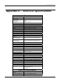
APPENDIX D - TECHNICAL SPECIFICATIONS.................................................113
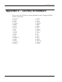
APPENDIX E – COUNTRY ID NUMBERS .......................................................115
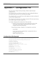
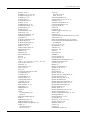
APPENDIX F – CONFIGURATION FILE ..........................................................116
Configuration File Example .................................................................................................... 116
INDEX .......................................................................................................118
DI-308 ISDN Remote Router
Introduction
Congratulations on your purchase of a D-Link DI-308 remote access router with
integrated Ethernet switch and ISDN T/A. No larger than an ordinary modem, your
router offers inexpensive yet complete telecommunications and internetworking
solutions for your home or branch office. It is ideal for everything from Internet
browsing to receiving calls from Remote Dial-in Users and making connections to
other LANs via Remote Nodes.
Distinguishing features of the DI-308 include support for a full range of networking
protocols including TCP/IP (Transmission Control Protocol/Internet Protocol).
This complete solution also includes remote dial-in user support, an Internet singleuser account (Network Address Translation) option, extensive network management
capabilities, and solid security features.
Product Features
The DI-308 router is packed with features that give it the flexibility to provide a
complete networking solution for almost any small to medium-sized office
environment.
Ease of Installation
Your DI-308 is a self-contained unit that is quick and easy to install. Physically, it
resembles an external modem; however, it is a combination ISDN router and
Ethernet switch, and it uses twisted-pair Ethernet cables to connect to the host
network.
Built-in Switch
A dual-speed NWay switch, the DI-308 provides eight ports for connecting network
end nodes—single-user computers, servers, bridges, other routers, etc.—through
standard “straight-through” twisted-pair cables and one port for making an “uplink”
connection to another hub or switch through the same type of straight-through cable
used to connect end nodes.
ISDN Basic Rate Interface (BRI)
Using a standard S/T the DI-308 supports DSS1 ISDN switches. The two ISDN Bchannels can be used independently for two destinations, or they can be bundled
together for one high-bandwidth connection supporting bandwidth-on-demand.
1
DI-308 ISDN Remote Router
ISDN Leased Line
If the router is set up for an ISDN leased line, it can automatically initialize the
leased-line connection each time it is powered up.
Standard Phone Jacks
The router is equipped with two standard phone jacks for connecting telephones, fax
machines, or modems. This allows the ISDN line to be used for voice as well as data
calls.
Dial On Demand
The Dial On Demand feature allows a DI-308 to automatically place a call to a
Remote Node whenever there is traffic coming from any workstation on the LAN
(Local Area Network) to that remote site.
Bandwidth On Demand
Your DI-308 supports bandwidth up to 128 kbps over a single ISDN BRI line. It
incorporates MLPPP (Multi-Link PPP) to bundle two B channels over a BRI line. In
addition, the router dynamically allocates bandwidth between the two B channels,
increasing or decreasing bandwidth as needed to allow for greater efficiency in data
transfer. It supports BAP (Bandwidth Allocation Protocol) and BACP (Bandwidth
Allocation Control Protocol) to manage the number of links in the multi-link bundle.
Full Network Management
The DI-308 incorporates SNMP (Simple Network Management Protocol) support
and menu-driven network management via an RS-232 or Telnet connection.
RADIUS (Remote Authentication Dial in User Service)
The RADIUS feature allows you to use a central external Unix- or NT-based server
to support thousands of users.
PPP Security
The DI-308 supports PAP (Password Authentication Protocol) and CHAP
(Challenge Handshake Authentication Protocol).
RIP-1/RIP-2
Your DI-308 supports both RIP-1 and RIP-2 (Routing Information Protocol versions
1 and 2) exchanges with other routers.
DHCP Support (Dynamic Host Configuration Protocol)
DHCP (Dynamic Host Configuration Protocol) allows IP addresses to be
automatically and dynamically assigned to hosts on your network.
2
DI-308 ISDN Remote Router
Data Compression
The DI-308 incorporates Stac data compression and CCP (Compression Control
Protocol).
Networking Compatibility
The DI-308 is compatible with remote access products from other companies such as
Ascend, Cisco, and 3Com. Furthermore, they support Microsoft Windows 95 and
Windows NT remote access capability.
Applications for your DI-308
Some applications for the DI-308 include:
Internet Access
Your DI-308 supports TCP/IP protocol, which is the language used for the Internet.
It is also compatible with access servers manufactured by major vendors such as
Cisco and Ascend.
Network Address Translation (NAT)
For small office environments, the DI-308 allows multiple users on the LAN to
access the Internet concurrently through a single Internet account. This provides
Internet access to everyone in the office for the price of a single user.
NAT address mapping can also be used to link two IP domains via a LAN-to-LAN
connection.
LAN-to-LAN Enterprise Connections
The DI-308 can dial to or answer calls from another remote access router connected
to a different LAN. The DI-308 supports TCP/IP and has the capability to bridge any
Ethernet protocol.
Telecommuting Server
The DI-308 allows Remote Dial-in Users to dial in and gain access to your LAN.
This feature enables users that have workstations with remote access capabilities,
e.g., Windows 95, to dial in using an ISDN terminal adapter (TA) to access the
network resources without physically being in the office.
What This Manual Covers
This manual is divided into twelve parts.
3
DI-308 ISDN Remote Router
Chapter One, “Introduction,” describes many of the technologies
implemented in the DI-308 as well as product features, etc. DI-308 to
operate on your LAN.
Chapter Two, “Installation,” is designed as a step-by-step guide to
installing the router.
Chapter Three, “Configuration and Management,” provides detailed
explanations for the console program that is used to setup and configure the
router.
Chapter Four, “PROM System Configuration,” provides information on the
PROM program, an abbreviated version of the console program that is used
to download new software into the router in case of problems with the
console program.
Chapter Five, “Using Telnet,” describes how to setup and use telnet to
configure the router.
Chapter Six, “Using RADIUS Authentication,” describes how to setup and
use a RADIUS server to manage user authentication and centralize
passwords.
Appendix A, “Troubleshooting,” describes some common problems setting
up the router and suggests solutions.
Appendix B, “IP Concepts,” gives detailed explanations
recommendations for setting up an IP network on your LAN.
and
Appendix C, “IP Protocol and Port Numbers,” lists many commonly used
IP settings.
Appendix D, “Technical Specifications,” lists specifications about the
DI-308 ISDN router.
Appendix E, “Country ID Numbers,” lists country ID numbers which must
be entered when setting up the ISDN line on the router. These numbers
have no relation to the International Country Codes used by your telephone
company.
Appendix F, “Configuration File,” includes a sample configuration file.
Regardless of the application, it is important that you follow the steps outlined in
Chapter 2, “Installation,” to correctly connect your DI-308 to your LAN. You can
then refer to other chapters of the manual depending on your specific installation
requirements.
What This Manual Doesn’t Cover
This manual assumes that you know how to use your computer and are familiar with
your communications software. If you have questions about using either one, refer to
the manual for the product.
4
DI-308 ISDN Remote Router
Other Resources
For more information about your DI-308 check the following sources:
♦ Quick Start Guide.
♦ Support disk containing RouteMan, a Windows-based configuration program.
Packing List
Before you proceed further, check all items you received with your DI-308 against
this list to make sure nothing is missing. The complete package should include:
♦ One DI-308 ISDN router.
♦ One power adapter.
♦ One RS-232 cable.
♦ One unshielded twisted-pair (UTP) cable.
♦ One frequently asked questions (FAQ) and application notes diskette.
♦ One Quick Installation Guide.
♦ This User’s Guide.
Additional Installation Requirements
In addition to the contents of your package, there are other hardware and software
requirements you need before you can install and use your router. These
requirements include:
♦ An ISDN line.
♦ Ethernet connection(s) to your computer(s).
♦ A computer equipped with an RS-232 port and communications software
configured to the following parameters:
◊ VT100 terminal emulation.
◊ 9600 baud.
◊ No parity, 8 data bits, 1 stop bit.
After the router has been successfully connected to your network, you can make
future changes to the configuration using a Telnet client application.
5
DI-308 ISDN Remote Router
Installation
This chapter outlines how to connect your DI-308 to your LAN and ISDN line. Refer
to the diagrams below to identify all of the ports on your device when you make
connections.
Ordering Your ISDN Line
If you do not have an ISDN line installed already, we suggest that you order it from
your telephone company as soon as possible to avoid the long waiting period
common when ordering a new line. Use the information in this section to place the
order. If you have already installed your ISDN line, you can check the following
section to make sure that you can use all the features of your DI-308.
1. Contact your local telephone company’s ISDN Ordering Center.
2. Make sure DSS1 switches are available since these are the only switch types
currently supported by the DI-308.
3. When the telephone company installs your ISDN line, be sure to obtain the
following information:
◊ ISDN switch type.
◊ ISDN telephone number(s).
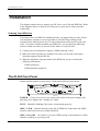
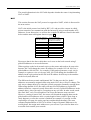
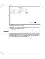
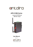
The DI-308 Front Panel
Names and descriptions of your router’s front panel LEDs are given below:
POWER— Comes on as soon as you connect the router to the power adapter and
plug the power adapter into a suitable AC outlet.
TEST— Should be blinking if the router is functioning properly.
ISDN – LINK— Indicates that the router has an ISDN line connected to the ISDN
interface and it has been successfully initialized.
ISDN – B1 and B2— On if there is an active ISDN session on that channel or if that
channel is making or receiving a call.
6
DI-308 ISDN Remote Router
LINK/ACT— 1 through 8— These indicators light up when a port is connected to a
powered-on Ethernet/Fast Ethernet station. The LEDs blink when information is
transmitted or received on a port.
100/10M – 1 through 8— These indicators light up when a port is operating at
100Mbps. Otherwise, if this indicator is dark and the corresponding LINK indicator
is lit, then the port is operating at 10Mbps.
PHONE – 1— Lights up when standard phone port 1 is in use.
PHONE – 2— Lights up when standard phone port 2 is in use.
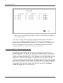
The DI-308 Rear Panel
POWER — This socket is an 18 volt, 750mA power input jack. If the power adapter
included with the router has been lost or misplaced, please ensure that the
replacement adapter meets both the voltage and amperage requirements.
CONSOLE – This 9-pin RS-232 port is used for connecting a console or PC
running a terminal emulation program. It provides out-of-band management
capabilities for the initial setup and configuration of the router.
PHONE 1 and 2 – These normal telephone jacks can be used to connect telephones
or fax machines to the router for use over the ISDN lines. Plug telephone devices
into these jacks as you normally would into a telephone wall socket.
ISDN – This socket is used to connect the ISDN line to either an NT-1 or directly to
the ISDN wall jack, depending on the type of service delivered by your phone
company.
ETHERNET – The eight Ethernet ports function as a normal, dual speed NWay
Ethernet switch.
•
Uplink – This port is used to connect the router to another switch or hub
using a straight-through twisted-pair cable. When the Uplink port is used,
Port 1x is unavailable.
•
Ports 1x to 8x – These eight ports can be used to connect end-stations to
the router using straight-through cables.
7
DI-308 ISDN Remote Router
Telephone Features
Up to two telephones can be attached to the DI-308 router via the Phone 1 and
Phone 2 telephone jacks located on the rear of the router. The router enables the
attached telephones to have a number of features which may or may not be found on
normal telephones and are described below. Additional features, which must be
configured, are described in the Interface Configuration – ISDN submenu section
of this manual.
• Hold – This feature is very similar with and can work in conjunction with call
waiting as defined in the Interface Configuration – ISDN submenu section of
this manual. Press Flash 0 to place someone on hold (Flash is a very brief
hanging up of the phone). Press Flash 2 to take the caller off hold.
• Hold (and pick up from another location) - Telephones connected to the router
can be put on hold by pressing Flash 71, 72, 73, or 74. Press the same number to
take the caller off hold and speak from another phone on your telephone network.
• Call forwarding – If you wish to forward incoming calls to a different telephone,
press *77* and then the phone number you wish to forward the call to. All
incoming calls will automatically be forwarded to the phone number entered.
Press #77# to cancel call forwarding.
• Three-person conference call – To use this feature, conference calling must be
enabled by the telephone company. After this is done, pick up a phone and place a
call. After connected, press Flash 0 (refer to call waiting in the Interface
Configuration – ISDN submenu section of this manual) and dial the second
number. After connected, press flash 3 to speak to both parties at the same time.
Press Flash 0 to hang up with the first party called. Press flash 1 to hang up with
the second party called.
• Call transfer – To transfer a call to the other phone jack on the router: if using
Phone 1, press flash 20. If using Phone 2, press flash 10.
Installation and Initial Configuration
This section discusses the different connections that can be made to the router when
setting it up.
Initially, you will only wish to connect the console to the router in order to configure
the other ports. Once that is complete, you will need to turn off the power to the
router and plug in the connection cables to the other devices. Next, power on the
other devices. When they have finished powering up, power on the router. Each of
these steps is described in detail in the sections below. Please skip any setting
adjustments that do not apply to your configuration needs.
8
DI-308 ISDN Remote Router
For the initial configuration of your DI-308, you must use an RS-232 console
connection, either to a computer running serial communications software or to a
serial data terminal.
After the router has been successfully installed and the initial configuration is
complete, you can continue to modify settings through the console, or you can
change configuration settings through a remote Telnet connection or through a Webbased configuration utilization program. See the chapters entitled “Configuration
and Management” and “Using Telnet” for detailed instructions on using Telnet to
configure your DI-308.
A Warning on Connection Cables
ISDN and Ethernet cables are very similar to each other. It is important that you use
the correct cable for each connection; otherwise, your router could be damaged.
Before connecting or disconnecting an RS-232 cable between two devices, turn both
devices off to avoid any chance of damaging them.
Step 1 - Setting up the Console
The initial setup of the DI-308, requires connecting a console to the 9-pin RS-232
Diagnostic port on the router’s rear panel. A serial cable is supplied with the
router in order to make this connection. A console can be a terminal, such as a
VT-100, or a normal PC running terminal emulation software (such as Microsoft
HyperTerminal, included with Windows). The terminal emulation software needs
to be configured to the following parameters:
◊ VT100 terminal emulation
◊ 9600 baud
◊ No parity, 8 data bits, 1 stop bit
◊ No flow control
Step 2 - Connecting the Console to the Router
A serial cable is included in the DI-308 package. To connect this cable, plug its ninepin connector into the 9-pin RS-232 Diagnostic port on the router’s rear panel, then
connect the other end to the serial port on the rear of your computer or data terminal.
Please make sure both machines are turned off before making this connection.
After the connection is made, first power on the console. If you are using a PC, run
the terminal emulation software at this time. After the PC and the terminal emulation
software are up and running, power on the router.
9
DI-308 ISDN Remote Router
Using the Console
The Console Program is the interface that you will be using to configure your
DI-308. Several operations that you should be familiar with before you attempt to
modify the configuration of your router are listed below:
• Moving the Cursor - Within a menu, use tab and arrow keys to navigate
through different information fields.
• Moving Forward to Another Menu - To move forward to a submenu below
the current one, use tab or arrow keys to position the cursor on the submenu
item and press <Enter> to view the selected submenu.
• Entering Information -There are two types of fields that you will need to fill
in. The first requires you to type in the appropriate information. The second
gives you choices to choose from. In the second case, press the space bar to
cycle through the available choices. Upon configuring all fields the submenu,
position the cursor on SAVE and press <Enter> to save, or position the cursor
on EXIT to cancel.
• Refresh Screen - Console screens are notorious for becoming garbled. When
this happens, simply press <Ctrl> + <R> to refresh the contents of the screen.
Step 3 - Connecting an ISDN Line to the Router
Your phone company will provide an S/T interface into your home or office. Plug
the ISDN line from the router directly into the ISDN wall socket provided by your
phone company.
Step 4 - Connecting a Telephone or Fax Machine to the Router
You can connect a regular telephone, fax machine, or modem to your router to be
used for analog calls. Note that the router’s other functions all work the same
whether you connect an analog device or not.
To connect an analog device, just plug one end of the device’s cord into one of the
sockets on the back of the router marked PHONE 1 or PHONE 2.
To have incoming calls directed to a device on a PHONE jack, you must enter the
telephone number for the phone in the console program under the Interface
Configuration, ISDN submenu.
Step 5 - Connecting Ethernet Cables to the Router
Your DI-308 has eight ports for connecting Ethernet devices to form a LAN. The
jacks for ports 1 through 8 are wired to let you connect network end nodes
(computers, servers, bridges, other routers, etc.) using up to 100M of standard
“straight-through” Category 5 UTP cable. In addition, an Uplink jack is wired to let
you connect to another Ethernet or dual-speed switch using a straight-through cable,
10
DI-308 ISDN Remote Router
or an end node using a cross-wired cable. Please note that when the Uplink port is in
use, Port 1x is unavailable.
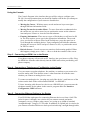
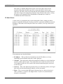
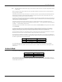
Please refer to the following chart when deciding on the type of cable necessary for a
given connection:
DEVICE
PORT
USED
Normal
Router
DEVICE BEING
CONNECTED
PORT
TYPE
Hub or
Normal
Crossover (X)
Switch
Uplink
Straight-Through (||)
Server (or PC)
Uplink
CABLE TO USE
Straight-Through (||)
Hub or
Normal
Straight-Through (||)
Switch
Uplink
Crossover (X)
Server (or PC)
Crossover (X)
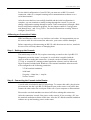
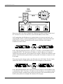
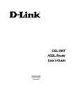
The figure below shows how to make an Ethernet connection between the router and
a network end node.
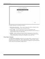
Important Notes on Ethernet Connections
Observe the following rules when connecting devices with twisted-pair Ethernet
cables:
• For both end-node and uplink connections, use only EIA Category 5 UTP
cables with RJ-45 plugs.
• Make sure no cable is more than 100 meters (328 feet) long.
• When uplinking two hubs together with a straight-through cable, use an
uplink-type jack at one end, and an end-node-type jack at the other.
• This is the maximum signal path in twisted-pair Ethernet. Also be sure never
to allow a signal loop to form.
11
DI-308 ISDN Remote Router
Note that you can connect an end node through the Uplink jack, but to do so
you must use a cross-wired cable or cable converter.
Step 6 - Powering Up Devices for Initial Configuration
Plug in the included 18V DC, 2.5A power adapter into the power jack on the
router’s rear panel.
You should have now connected the RS-232 cable to the console, the ISDN phone
line, one or more Ethernet cables, and the power adapter.
At this point in the installation process you can now power up the console computer,
run the terminal emulation software (if necessary), and then power up the DI-308.
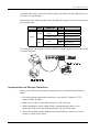
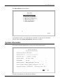
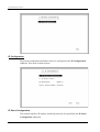
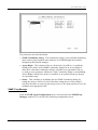
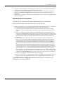
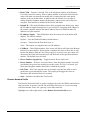
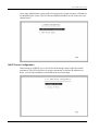
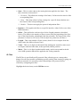
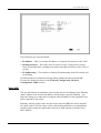
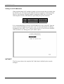
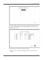
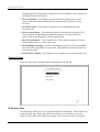
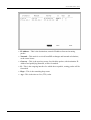
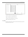
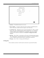
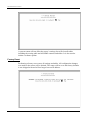
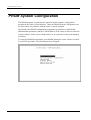
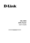
Step 7 - Initial Configuration of the Router
After the console is properly connected and both devices are powered on as
described in the preceding sections, you should see the router run through the power
on self test (POST). Finally, it will arrive at the logon screen shown below. If the
login screen does not appear, press <Ctrl> + <R> to refresh the screen.
12
DI-308 ISDN Remote Router
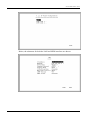
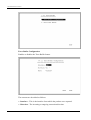
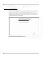
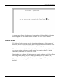
To log on to the router, use the factory set username and password ‘Admin’ (without
the quotes). Please note that the user name and password are case-sensitive.
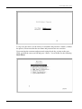
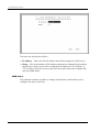
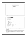
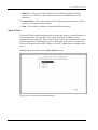
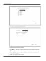
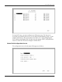
Upon entering the username and password (using the tab key to jump to the next
field), position the cursor on OK and press <Enter>. You will then see the following
Main Menu:
13
DI-308 ISDN Remote Router
Step 8 - Configuring the LAN Port
Preparing the router for connection to a LAN only requires enabling the LAN port,
enabling IP networking, assigning the LAN port an IP address and enabling telnet (if
necessary). After the LAN port is configured, all other features on the router can be
configured remotely through the LAN by using the included Windows-based Router
Configuration Utility or Telnet. Regardless, the router can always be configured
using a console connected to the RS-232 Console port.
To configure the LAN:
1. The LAN port must be enabled in the Interface Configuration submenu.
• Choose Interface Configuration, LAN.
• Position the cursor over the State item and press <space bar>.
• Position the cursor on the Save option at the bottom of the screen and press
<Enter> to save the new setting.
• Choose Exit in the submenus to return to the Main Menu.
2. Enable IP Networking
• Choose Network Configuration, IP Configuration.
• Position the cursor over the last item IP Networking and press <space bar> to
enable it.
• Position the cursor on the Save option at the bottom of the screen and press
<Enter> to save the new setting.
3. Assign an IP address to the LAN port in the Network Configuration submenu of
the Main Menu.
• Still in Network Configuration, IP Configuration submenu from Step 2
above, choose IP Stack Configuration, LAN.
• Enter a valid IP address for the LAN in the first item. You may also enter a
Netmask if you wish. For more information about IP Addresses and Subnet
masks, please refer to Appendix B, “IP Concepts.”
• Position the cursor on the Save option at the bottom of the screen and press
<Enter> to save the new setting.
• Choose Exit in the submenus to return to the Main Menu.
4. Enable the Telnet/Discovery function on the router.
• From the Main Menu choose Advanced Functions.
14
DI-308 ISDN Remote Router
• Choose the Telnet/Discovery Enable option to enable Telnet if it has not been
done so already.
• Position the cursor on the Save option at the bottom of the screen and press
<Enter> to save the new settings.
• Choose Exit in the submenus to return to the Main Menu.
The router can now be accessed via the LAN by Telnet, the Web-based DI-308
Router Configuration Utility (included with the router) and other SNMP
management applications.
If you have any questions regarding the settings you made or other settings in the
submenus, please refer to the next chapter, “Configuration and Management.”
Step 9 – Plugging in All Devices
You can now plug in and power on all other devices connected to the router. Then
power on the router.
The router is now able to use the LAN ports.
The router must be further configured in order to get the built-in ISDN modem to
function properly, to perform other routing functions, and to manage your IP
network. This can now be done by using the console, the included Web-based
Configuration Utility or Telnet.
For more information about configuring or managing the router, please refer to the
next chapter, “Configuration and Management.”
15
DI-308 ISDN Remote Router
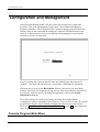
Configuration and Management
After the initial startup (POST) test, the router will prompt you for login and
password. This is the opening page of the router’s out-of-band configuration
program, called the Console program. The Console program is stored in the Flash
memory chips in the router and the settings are written in EEPROM chips in the
router. It is the most basic level for configuring and managing the router and the
network to which it is connected.
If you’re starting the router for the first time, the default login and password is
“Admin” – the login and password are case-sensitive, alphanumeric characters.
Note that once you are in the Main Menu, if there is no activity for more than 5
minutes, the router will automatically log you out. Your first endeavor should be to
increase the ‘timeout’ time by adjusting the appropriate value in the System
Information submenu.
The router can also be configured remotely by using the included Router
Configuration Utility or through Telnet. However, if you wish to do this, the console
program must first be used to initially configure the relevant port on the router.
Please see Step 7 - Initial Configuration of the Router on page 12 of this manual for
more detailed information.
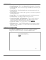
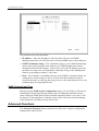
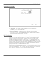
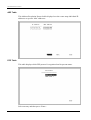
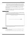
Console Program Main Menu
16
DI-308 ISDN Remote Router
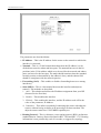
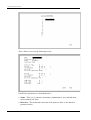
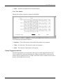
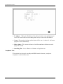
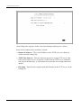
The Main Menu is shown below:
As mentioned earlier, your first endeavor should be to increase the automatic
timeout. Enter the System Information submenu to do this.
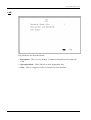
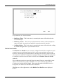
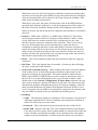
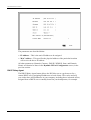
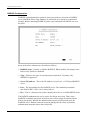
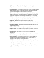
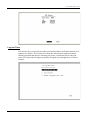
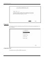
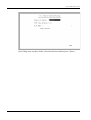
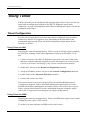
System Information
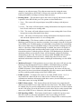
This menu contains administrative and system-related information.
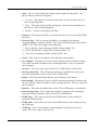
The above parameters are described as follows:
17
DI-308 ISDN Remote Router
• System Description – This is a non-changeable, short description of the product.
• System Object ID – This is the enterprise-specific MIB Object ID indicating this
type of router.
• System Up Time – Shows how long the router has been running since the last
power on or reset.
• System Contact – Enter the name of the department or individual responsible for
maintaining the router.
• System Name – Give the router a descriptive name for identification purposes.
• System Location – Enter the geographic location of the router.
• Console/Telnet Display Timeout in Minutes – This is a security measure to
automatically logoff from the console menu after a given idle time. Enter a
timeout time between 0 and 90 minutes. Zero specifies no timeout.
• System MAC Address – The physical address of this router.
• ISDN Switch Type – The type of ISDN switch used by the telephone company
that the DI-308 can communicate with. The DI-308 currently supports only the
DSS-1 switch type.
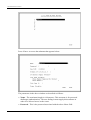
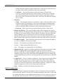
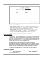
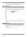
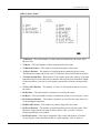
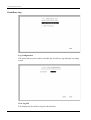
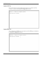
Interface Configuration
Under Interface Configuration in the main menu is the following interface
configuration screen, used to configure the LAN and ISDN interfaces:
18
DI-308 ISDN Remote Router
LAN
The parameters are described below:
• Description – This is a user-defined, 32-character identifier used to name the
LAN.
• Operation Mode – The LAN port is Auto Negotiation only.
• State – This is a toggle to Enable or Disable the LAN interface.
19
DI-308 ISDN Remote Router
ISDN
The parameters are described below:
• Description – This is a user-defined, 32-character identifier used to name the
ISDN.
• Switch Type – This parameter defines the type of ISDN service used. Currently,
the DI-308 only supports DSS-1 type ISDN lines.
• B1 and B2 Channel Usage – This defines whether the ISDN line is a leased line
or a normal switched line. If you are not using a leased line connection, set this
item to Switch.
• Country ID – This field needs to contain the country parameter. Without this
information, the router cannot establish a connection. A list of country ID
numbers is located in Appendix E, “Country ID Numbers.”
• ISDN Data – This field must contain the incoming telephone number for data
calls. In other words, it is your ISDN line’s data phone number.
• A/B Adapter 1 and 2 – Enter the telephone numbers for your voice/analog lines.
• Phone 1 and 2 Call Waiting – If you have applied for and received call waiting
capabilities for your ISDN voice lines, you must enable these settings in order for
the call waiting feature to function.
There are four special operations for using call waiting (flash means a very brief
hanging up of the phone. In other words, for the first option below, flash 0, click
the hang up button on your phone very quickly and then press the number 0 on
your telephone’s keypad):
20
DI-308 ISDN Remote Router
Flash 0 – disconnect the first phone call established.
Flash 1 – disconnect the second phone call established.
Flash 2 – switch between the two phone calls.
Flash 3 – speak to both parties simultaneously (if conference calling is enabled by
your phone company).
• POTS Lines – [Plain Old Telephone Service]. Enables or disables phone calls on
the Phone 1 and Phone 2 jacks on the rear of the router.
• Global Reception – When this is enabled, the Phone 1 and Phone 2 jacks will
receive all phone calls directed to them by the telephone company’s switch. When
disabled, the router will check incoming calls to the Phone 1 and 2 jacks against
the telephone numbers specified in the A/B Adapter 1 and 2 fields above.
• Block Outgoing CLID – When this is enabled, your ISDN data phone number
and voice phone numbers will never be sent out when trying to establish a
connection. Thus, even if sites being called have Caller ID, they still won’t be
able to know your phone number.
• Inbound Authentication – This defines the authorization protocol that will be
used when accepting a dial-in connection. The choices are Password
Authentication Protocol [PAP], Challenge Handshake Authentication Protocol
[CHAP] or None. PAP and CHAP do not provide a screen for users to manually
enter their Username and Password – instead, this data must be entered into the
dialing software before placing the call. Make sure the device dialing in is using
the same protocol as defined here. The None setting may be used when you do not
wish dial-in users or networks to identify themselves or be subject to security.
• Call Bumping – This setting only takes effect when both B channels are
connected and using multi-link PPP. If this is the case and call bumping is
enabled, when you receive an outgoing voice call, the second B channel will be
dropped (with all traffic being moved to the first B channel) and the voice call
will be received. If disabled, both B channels will continue their data
transmissions uninterrupted and the voice call will be ignored.
• State – Enables or disables the ISDN port.
Network Configuration
There is one main item on the DI-308 Network Configuration menu:
21
DI-308 ISDN Remote Router
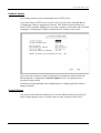
IP Configuration
IP protocol configuration and static routes are configured in the IP Configuration
submenu. This menu is shown below:
IP Stack Configuration
The network interface IP address, mask and protocols are specified in the IP Stack
Configuration submenus.
22
DI-308 ISDN Remote Router
Below, the submenus for both the LAN and ISDN interfaces are shown:
23
DI-308 ISDN Remote Router
The parameters are described below:
• IP Address – This is the IP address for the router on the network to which this
interface is connected.
• Netmask – This is a 32-bit bit mask that shows how the IP address is to be
divided into network, subnet and host parts. The netmask has ones in the bit
positions in the 32-bit address which are to be used for the network and subnet
parts, and zeros for the host part. The mask should contain at least the standard
network portion (as determined by the address's class), and the subnet field
should be contiguous with the network portion.
• Forwarding (LAN) – This enables or disables forwarding between or among
interface(s).
• State (ISDN) – This is a link method between this interface and adjacent
router(s). The methods are described:
1. Auto – This obtains and utilizes the IP address assignment from your ISP
(Internet Service Provider).
2. Disable – This disables this interface.
3. IP Stack – This enables this interface, and the IP address used will be the
value of the parameter, IP Address.
4. Unnumber – This utilizes a method of connecting this router with adjacent
routers, without having to define an IP network prefix between them. The
adjacent routers must have UNNUMBER capability too.
• Routing Protocol – This is a distance vector routing protocol. RIP is an Internet
standard Interior Gateway Protocol defined in RFC 1058 and RFC 1723. Routing
information is sent periodically (each 30 seconds, or triggered by topology
24
DI-308 ISDN Remote Router
change) to an adjacent router. The adjacent router must be using the same
protocol. Setting this to RIPV1&V2 will give the router the ability to make
routing information exchanges with any adjacent router.
• Routing Mode – This parameter allows the router to specify the extent to which
it partakes in the RIP on this port. The options are described below:
1. None – The router will not participate in any RIP exchange with adjacent
routers.
2. Listen – The router will incorporate routing information from adjacent routers,
but will not send its own routing table.
3. Talk – The router will send adjacent routers its own routing table, but will not
incorporate routing information from them.
4. Both – The router will incorporate routing information from adjacent routers,
and will send adjacent routers it’s own routing table.
• IP Multicasting – This feature enables or disables the router’s ability to route IP
Multicast packets from one interface to another (for example, from the LAN ports
to the ISDN port). IP Multicasting is a bandwidth-saving method for transmitting
data to more than one host. IP Multicasting is often used when sending/receiving
audio or video data. When IP Multicasting is enabled, the router will search its
multicast forwarding table and depending on the result of the search will either
forward the packet or add the group to the table. If IP Multicasting is disabled, all
multicast packets received by the router will be dropped, effectively limiting
multicasting to the LAN. The router can also perform DVMRP if this feature is
enabled (see Multicast Protocol below), which allows the DI-308 to share
multicast information with other routers, enabling IP multicasting over the ISDN
port.
• Multicast Protocol – If this parameter is set to None, the router will only use the
Internet Group Management Protocol (IGMP), if IP Multicasting is enabled
above. This effectively limits multicast data to the local network. If set to
DVMRP (Distance Vector Multicast Routing Protocol), the router will also use
this protocol to share its multicast information with other routers (much like RIP),
in effect, enabling multicasting on the WAN (ISDN) port.
• IGMP Version – Configures the router to use either IGMP version 1 or 2. A
major difference between the two is that version 2 allows the router to
communicate multicast information with other routers (via the ISDN port), even
if the other router isn’t using DVMRP.
• DHCP Client (LAN) – This feature allows the LAN port to be assigned an IP
address from a DHCP server other than the one in the router. This feature should
be enabled only for special configurations (such as the presence of a cable modem
on the LAN) where you wish the router to work with a device on the network that
must act as a DHCP server. Otherwise, this feature should be kept disabled.
• RIP Spoofing (ISDN) – This feature should only be enabled if you have more
than one router on your network and this router is providing your WAN
connection. In this case, if the WAN connection is dropped due to inactivity and
25
DI-308 ISDN Remote Router
this feature is enabled, RIP packets will be sent to the other routers on the
network telling them that data can still be sent to the WAN via this router.
Otherwise, the other routers will learn that the WAN link has been disconnected
and will no longer forward packets destined for the WAN to this router, causing
the packets to be dropped before Bandwidth on Demand has a chance to
reestablish the WAN connection.
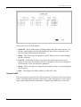
IP Static Route
A static route is a permanent entry in the routing table. Static routing provides a
means of explicitly defining the next hop router for a particular destination network
IP address. Each static route entry also allows for a metric (a.k.a. hop count) to be
specified.
The parameters are described below:
• IP Address – This specifies the destination network IP address (or a host,
depending on the netmask) and pairs it with a gateway.
• Netmask – This mask shows how the destination IP address is to be divided into
network, subnet and host parts. The netmask has ones in the bit positions in the
32-bit address which are to be used for the network and subnet parts, and zeros
for the host part.
• Gateway – This is the adjacent next hop router, for which the packets, arriving to
this router with this destination IP address, will be forwarded.
• Hops – This is an associated RIP metric that may have its value set between 1
and 15, inclusive. A metric value higher than 15 (such as 16) means that the
network is unreachable.
26
DI-308 ISDN Remote Router
• Intf – This is the network interface containing the gateway that the packets will
be forwarded through.
• State – This enables or disables a particular entry.
IP Static Route Examples
The IP Static Route Table shown in the example IP Static Route screen above has
the first three entries configured for common implementations of static routing.
The first entry assumes that ISDN1 has a connection to the Internet and defines the
default next hop router. If you use this router to connect to the Internet it is very
important that you create an entry here that defines the default next hop router as
your ISP. This configuration is also commonly used when RIP exchanges with other
Internet routers (on ISDN1) are disabled.
The second entry shows how to configure static routes when there is another router
on the LAN. The IP Address shown (202.12.125.0) is the network address for a
branch office, for example. The Gateway Address (210.172.23.1) is the IP address to
the LAN port on another router on the LAN that maintains an ISDN connection to
the branch office.
The third entry is an example of an enterprise ISDN connection (through telephone
lines) to another router, at a branch office for example. The IP Address is the
network address of the branch office. The Gateway Address is the IP Address of the
ISDN port on the branch office router. This configuration assumes there is a modem
on ISDN2 maintaining a dial-up connection to the branch office.
IP Networking
Under the IP Configuration submenu, the IP Networking function can toggle to
connect/disconnect this router from the entire IP network.
When IP Networking is disabled, all routing functions are stopped. The only IP
Address the router will act on is its own, via Telnet for example.
Router Advertisement
When this option is enabled, the router will periodically send out ICMP packets that
announce itself on the network. These ICMP packets are utilized by the Windows 98
or later operating system, which will automatically update the default gateway
setting on the computer in which it is installed.
SNMP Agent Configuration
The Simple Network Management Protocol (SNMP), defined in STD 15, RFC 1157,
is a protocol governing the management and the monitoring of IP network devices
and their functions. The DI-308 supports the use of SNMP to acknowledge
communication between management stations and itself. Basically, the DI-308,
27
DI-308 ISDN Remote Router
when connected to the network, acts as an SNMP agent, a software process that
responds to queries using SNMP to provide status and statistics about the router.
Following is a description of how to configure the DI-308 for SNMP management.
From the Main Menu, select SNMP Agent Configuration. This will bring you to
the SNMP Agent Configuration menu, shown above.
SNMP Community Configuration
Select and enter the SNMP Community Configuration submenu. You will see the
following configuration screen:
28
DI-308 ISDN Remote Router
The parameters are described below:
• SNMP Community String – This community string is a user-defined identifying
name used to group together some arbitrary set of SNMP application entities
managed by the network manager.
• Access Right – This element of the set {Read Only, Read/Write} is called the
SNMP access mode. If the SNMP Community String has an Access Right of
Read/Write, then that Community String is available as an operand for the get,
set, and get next operations. Otherwise, if the Community String’s corresponding
Access Right is Read Only, then it is available as an operand for the get and get
next operations only.
• Status – This validates or invalidates the use SNMP Community String, by
setting the string to Valid or Invalid. Note that setting the use of the string to
Invalid is the same as removing the string, however, the string remains so as to be
validated at an appropriate time.
SNMP Trap Manager
From the SNMP Agent Configuration menu, select and enter the SNMP Trap
Manager submenu. You will see the following configuration screen:
29
DI-308 ISDN Remote Router
The parameters are described below:
• IP Address – Enter the IP address of the host who will act as an SNMP
Management Station. The DI-308 router will send SNMP traps to these addresses.
• SNMP Community String – The community string is a user-defined identifying
name used to group together some arbitrary set of SNMP application entities
managed by the network manager. Traps will be sent to the IP Address (previous
parameter) as long as the corresponding Community String, in the Management
Station’s trap manager software, is the same.
• State – This validates or invalidates the use of the SNMP Community String, by
setting the use of the string to Valid or Invalid. Note that setting the string to
Invalid is the same as removing the string, however, the string remains so as to be
validated again at an appropriate time.
SNMP Authenticated Trap
Returning to the SNMP Agent Configuration menu, you can Enable or Disable an
authentication failure trap message being sent to the Management Station by the
router. When an SNMP packet with an invalid community name is received, it will
be dropped. If this parameter is enabled, a trap will be sent to the network manager;
if this parameter is disabled, no trap will be sent.
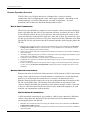
Advanced Functions
The Advanced Functions menu contains most of the more complex configuration
settings and is shown below:
30
DI-308 ISDN Remote Router
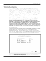
Remote Access Configuration
The Remote Access Configuration menu is used to set up the router for dial-in and
dial-out connections over the ISDN line. An ISDN line has a D channel for
establishing connections and two B (Bearer) channels, which transmit and receive
the actual signals, whether voice or data. The two B channels can support two
independent remote connections or be banded together using Multi-link PPP to
implement Bandwidth on Demand (configured separately in the Multi-Link PPP
Configuration menu, the last item in the Advanced Functions window).
The B-Channels can also carry voice and fax calls, which are routed to the telephone
jacks located on the rear of the router. Please note, however, that the DI-308 can
maintain only two connections at a time via the two B channels, whether the
connections are voice, data, dial-in users, remote networks or a combination thereof.
31
DI-308 ISDN Remote Router
Remote Operation Overview
The DI-308 is very flexible and can be configured for a variety of remote
connections. Since configuring the router can be quite complex - depending on the
number and type of remote connection(s) you wish to implement – we have
described some of the basic functions and procedures below.
Dial-In User Connections
Dial-in users are defined as a single user on a computer, such as a person working at
home, who dials into the office to use network resources. In almost all cases, a DialIn User Profile needs to be set up for each user who will dial in to the router so the
router can tailor the connection for each user. Once this is done, the remote user will
be able to use network resources as if he were connected locally. When the user dials
into the DI-308, the call comes into the D-channel and after answering the phone, the
DI-308:
1. Identifies the Username and Password using the authentication protocol defined in the Interface
Configuration, ISDN submenu. The dial-in user is not prompted for this information, but must
enter it into his dialing software before dialing.
2. Checks the Username and Password against those defined in the Dial-In User Profiles and Remote
Network Profiles.
3. Assuming a matching Dial-In User Profile is found, the router may configure the IP address of the
remote station (as defined in the Dial-In User Profile).
4. Configures a dial-in Interface (a virtual circuit) to handle the connection.
5. Establishes the connection on whichever B-channel (physical port) is open by mapping the dial-in
interface to that port.
6. In the case where the Dial-In User does not need to supply a Username and Password (Auth Type
is set to None in the Interface Configuration submenu) the remote computer must have its own
IP address.
Remote Network Connections
Remote networks are defined as other networks (LANs) that have WAN connections
using a router, Internet server, network modem or similar device (in this document
however, we will assume the remote device is a router). In almost all cases, a
Remote Network Profile needs to be set up for each network that will connect to the
DI-308 via the ISDN lines. The Remote Network Profiles are necessary for the
router to identify and tailor the connection to the remote network’s router. Once this
is done, a connection between the two routers can be made and computers on each
network can communicate with each other.
Dial-In Network Connections
A dial-in network connection is very similar to a dial-in user connection. When the
remote router dials into the DI-308, the call comes into the D-channel and after
answering the phone, the DI-308:
1. Identifies the Username and Password using the authentication protocol defined in the Interface
Configuration, ISDN submenu.
2. Checks the Username and Password against those defined in the Dial-In User Profiles and Remote
Network Profiles.
32
DI-308 ISDN Remote Router
3. Assuming a matching Remote Network Profile is found, the router may configure the IP address
of the remote station (as defined in the Remote Network Profile).
4. Configures the specified ISDN Interface (a virtual circuit) using the configuration parameters
defined in the Interface Configuration menu and the Remote Network Profile to handle the
connection.
5. Establishes the connection on whichever B-channel (physical port) is open by mapping the dial-in
interface to that port.
Dial-Out Network Connections
Dial-out network connections are much different than dial-in connections.
When a packet on the LAN reaches the router, the DI-308 will:
1. Check its routing table to try to identify where this packet should go. It looks for two variables in
the routing table, Gateway address and Interface. There are four possible results:
I. In the case where the destination resides in the same IP network on the LAN, the routing
engine never acts on the packet and it is sent directly to the destination through the built-in
switch.
II. In the case where the destination resides on a different IP network on the LAN (which can
happen when Multiple Home Configuration is set up), the router will send out an ARP request
to obtain the MAC address of the destination computer (or router) and deliver the packet. Note
that defining Static ARPs can speed up delivery since the router won’t need to send out an
ARP request.
III. In the case where the router finds a match in the routing table (which includes IP Static
Routes), it uses the Gateway address and Interface numbers to identify the correct Remote
Network Profile to use to dial out. From the Remote Network Profile, the router gets the
telephone number and other information and dials out, establishes a connection and delivers
the packet. If you have a connection to the Internet, it is very important that you define the
default next hop router in the IP Static Routes submenu of the console program as your ISP
(see the IP Static Routes section of this manual for more detailed configuration information).
This is because if a user on your LAN makes a request to download a web page for the first
time, for instance, since it is the first time, the DI-308 will not have any record of the web
page’s IP address. If no default next hop router is defined, the request will be dropped and the
user will get a ‘Destination Unreachable’ error message. However, if a default next hop router
is defined on the IP Static Routes screen, the DI-308 will pass this request on to the ISP (the
request will go through) and the user will receive the web page.
IV. In the case where there is no match for the destination IP address in the routing table, and no
default next hop router is defined, the packet will be dropped and no action will be taken.
The Remote Access Configuration submenu is shown below. All items in the
submenu are described as follows.
33
DI-308 ISDN Remote Router
34
DI-308 ISDN Remote Router
Dial Configuration
You can configure the two ISDN interfaces on your DI-308 to dial-out only when a
packet is forwarded to that interface, and hang up after all data has been transferred
and the link is idle. This can be used to lower the cost of an unpopular link or used
as a backup link to your ISP. This feature is commonly called “Dial on Demand.”
ISDN interfaces can also be configured here to receive calls from dial in users and
other networks, called “Remote Access.” Please note however, that in all cases, after
configuring the ISDN Links in the Dial Configuration submenu, they must be
further configured in the Dial-In User Profile submenu or Remote Network Profile
submenu.
Dial In IP Pool
The dial in IP pool allows you to define a range of IP addresses that will be reserved
for and assigned to dial-in users.
35
DI-308 ISDN Remote Router
The items are described as follows:
• IP Address – This is the first IP Address that will be assigned to a dial-in user.
• Range – This is the number of IP Addresses that can be assigned. In the window
shown above, dial-in users will be assigned the IP Addresses 170.100.200.1 or
170.100.200.2 (only two are necessary since the router used in the examples has
only two ISDN ports).
ISDN Link 1
This submenu contains a number of settings (shown below) which allow you to
configure the router to dial out.
36
DI-308 ISDN Remote Router
The parameters are described below:
• Dial Retry Time – This is the time (in seconds) the router will wait before the
next dial attempt.
• Dial Retry Count – This is the specified maximum number of dial attempts the
router will make when trying to establish a connection on this interface.
• Call Back Delay – This is the time (in seconds) the router will wait before calling
the number designated for a specified dial-in user.
Dial-In User Profile
The Dial-In User Profile screen is used to configure the DI-308 for single users (for
example a person working at home) to dial in to the router and gain access to the
network. At least one User Profile must be configured for each user who will dial in
(in conjunction with Dial Configuration settings). Please note that WAN connections
to computers on other networks must be defined in the Remote Network Profile
submenu.
Up to eight users can be set up to dial in to the router. However, more dial-in users
can be accommodated by using a RADIUS server as described in the RADIUS
Configuration section of this manual. Please note that when a RADIUS server is
being used, the Dial-in User Profiles will be disabled.
Highlight one of the eight entries on the Dial-In User Profile screen displayed
below:
37
DI-308 ISDN Remote Router
Press <Enter> to access the submenu that appears below:
The parameters in the above window are described as follows:
• Name – The maximum length is 64 characters. This username is for password
challenges (authentication). The user dialing in must supply this username in
order to be allowed access to the router.
• Password – This is the password associated with the above Name field.
38
DI-308 ISDN Remote Router
• Rem CLID – Remote Caller ID. This is the telephone number of the Remote
User and is used for security. When a phone number is entered in this field, the
router will make sure that the incoming call is coming from the same phone
number as the one defined here. In other words, the remote user can only be
calling from the telephone number defined here, otherwise the call will not be
accepted. This function is disabled if the field is left blank.
• Default IP – This is the IP address that will be assigned to the dial-in user when
the IP Address Supply setting below is set to Default. Assigning an IP address to
the remote computer ensures that the IP address does not clash with other IP
addresses on your network.
• IP Address Supply – This field defines how the remote user will obtain an IP
address. The choices include:
Default – Uses the Default IP address defined above,
Dynamic - Taken from the Dial In IP pool, or
None - The remote user supplies their own IP Address.
• Call Back – This field determines if the router will allow call back to the Remote
Dial-In User upon dial-in. If this option is enabled, the router will be able to call
back to the Remote Dial-In User if they request it. In such a case, the router will
disconnect the initial call from this user and dial back to the specified call back
number. The default is no call back.
• Phone Number Supplied by – Toggle between Router and Caller.
• Phone Number – If Router is selected above, then this phone number is usually
provided by the person who initially set up the router. If Caller is selected, you
must enter the phone number that will be called back yourself.
• Idle Time – This is the elapsed time (in seconds) since the last valid or active
packets have gone through the router. This setting will trigger the router to
disconnect this interface when it is reached.
• State – Enables or disables this User Profile.
Remote Network Profile
The Remote Network Profile is used to configure the router for ISDN connections to
other networks. In practice, the DI-308 will either dial-out to or receive incoming
calls from another router, the ‘gateway’ to the other network.
Highlight one of the eight entries on the Remote Network Profile screen:
39
DI-308 ISDN Remote Router
Press <Enter> to access the submenu that appears below:
• Remote Name – Name for the remote network that the DI-308 is being set up to
connect with.
• Direction – Dial-[In], dial-[Out], or [Both]. This field defines whether the router
on the other network will dial-[In] to the DI-308 to establish a connection, the DI308 will dial-[Out] to the other network, or a connection can be established
[Both] ways.
40
DI-308 ISDN Remote Router
When this is set to In, the DI-308 will only establish a connection with the other
network by receiving calls on the ISDN port specified in the Interface field below.
Also, the incoming calls will be subject to the Name, Password and Rem CLID
fields in the Incoming section below.
When this is set to Out, the router will only make calls on the ISDN interface
specified in the Interface field below. Also, the outgoing calls will be subject to
the Name, Password and Phone Number fields in the Outgoing section below.
When set to Both, the dial in and dial out conditions described above will both be
observed.
• Interface – ISDN Link 1 [ISDN L1] or ISDN Link 2 [ISDN L2]. This field is
used to assign a remote network to a logical (virtual) interface called a virtual
circuit. More than one remote network can be configured to use the same
interface, but they cannot be connected at the same time. Thus, if you wish to
have two WAN connections operate simultaneously, make sure they are
configured on different interfaces. On the other hand, if you have two dial-out
remote network profiles but wish to keep one line always open for dial-in users,
make sure the two dial-out profiles use the same interface. In this case, the two
profiles will share the same interface; the second one using it after the first one’s
idle time has expired and it has relinquished it.
• Phone – This is the telephone number that will be dialed to make the outgoing
connection.
• Idle Time – This is the elapsed time (in seconds), of inactivity, that will trigger
the router to disconnect this interface.
• Set Peer IP as default Gateway – When enabled, this feature sets the IP address
of the remote device as the default gateway (default next hop router) for all
packets not found in the routing table. This option should be enabled for the
ISDN circuit (ISDN1 or ISDN2) that is used to connect to the Internet. Also, if
the Peer IP is set as the default gateway here, you still need to define a static
default route in the Network Configuration, IP Static Route submenu, but you
don’t need to designate a gateway IP address for the static route (the routers will
automatically negotiate and adjust the gateway IP setting accordingly). And also
make sure that the Remote IP Address in the Remote Networks Profile is set to
0.0.0.0. Note that only one ISDN circuit should be connected to the Internet, and
only one ISDN circuit (the same one) should be the default gateway.
• Incoming
• Name – The maximum length is 64 characters. This username is for password
challenges (authentication). The user dialing in must supply this username in
order to be allowed access to the router.
• Password – This is the password associated with the above Name field.
• Rem CLID – Remote Caller ID. This is the telephone number of the Remote
User and is used for security. When a phone number is entered in this field, the
router will make sure that the incoming call is coming from the same phone
number as the one defined here. In other words, the remote user can only be
41
DI-308 ISDN Remote Router
calling from the telephone number defined here, otherwise the call will not be
accepted. This function is disabled if the field is left blank.
• Call Back – This field determines whether the router calls back after
receiving a call from this Remote Network Profile. If this option is enabled,
the router will disconnect the initial call and call back to the phone number
that you provide. Note that this field will be valid only if the Direction setting
above is Both.
• Outgoing
• Name – The maximum length is 64 characters. Spaces and punctuation are not
usually accepted. This username is for password challenges (authentication)
which are automatically handled by the router when dialing out. The DI-308
will use PAP and CHAP (whichever works) to make the connection.
• Password – This is the password associated with the above Name field.
• Remote IP Address – This is the IP address that will be assigned to the dial-in
network when the IP Address Supply setting below is set to Default. Assigning an
IP address to the router dialing in ensures that the IP address does not clash with
other IP addresses on your network. For dial out connections utilizing dial on
demand, the IP address of the remote router needs to be entered here so the router
knows which remote network to establish a connection with to deliver the packet.
• IP Address Supply – This field defines how the router will assign an IP address
to a device dialing in. The choices include:
Default – Uses the Remote IP address defined above,
Dynamic - Taken from the Dial In IP pool, or
None - The remote user supplies their own IP Address.
• Multi-Link PPP – Enables or disables multi-link PPP on this remote node. Both
MLPPP and Bandwidth On Demand (BOD) must be enabled for BOD to
function. If MLPPP is enabled and BOD is disabled, then both ports will dial up,
establish a direct connection, and combine the bandwidth of the two connections
using the MLPPP protocol. Please note that the DI-308 contains only one MLPPP
bundle.
• Compression – This is an industry standard, 4:1 Stac compression scheme. When
enabled, the router will try to use compression on this remote node whenever
possible. If the destination device is not capable of using Stac compression, the
two devices will still communicate, albeit without using Stac compression. When
disabled, compression will never be used on this remote node.
• State – Enables or disables this Remote Network Profile.
DHCP Configuration
The DI-308 Router implements the Dynamic Host Configuration Protocol (DHCP),
which allows the entire IP network to be centrally managed by the router. It does this
by assigning IP addresses and configuration parameters to hosts as they are powered
on and come onto the network. This can be a great help for network administration
42
DI-308 ISDN Remote Router
since many administrative tasks such as keeping track of each computer’s IP address
are handled by the router. The DI-308 can implement DHCP in one of the two ways
shown below:
DHCP Server Configuration
When acting as a DHCP server, the DI-308 will manage many of the IP network
parameters. The DI-308 will never assign a broadcast or network IP addresses to
hosts, even if such an address is included in the specified range.
43
DI-308 ISDN Remote Router
Dynamic IP Pool
The Dynamic IP Pool screen shown below contains the parameters that the router
can set on the hosts. Please note that the dynamic IP pool cannot be enabled when
the DHCP Agent feature is enabled.
The parameters are described below:
• IP Address – This is the base (starting) address for the IP pool of IP addresses to
be assigned.
• Range – This is the range of contiguous, IP addresses, above the base IP Address
above. In the above example, the IP addresses assigned host computers as they
come onto the network would be 202.93.47.1, 202.93.47.2 … 202.93.47.100.
• Netmask – This mask informs the client, how the destination IP address is to be
divided into network, subnet and host parts. The netmask has ones in the bit
positions in the 32-bit address which are to be used for the network and subnet
parts, and zeros for the host part.
• Gateway – This specifies the Gateway IP Address that will be assigned to and
used by the DHCP clients.
• Lease Time – This specifies the number of hours a client can lease an IP address,
from the dynamically allocated IP pool. The maximum value is 65535 and a value
of 0 means the lease is permanent.
• DNS IP – This specifies the Domain Name System server, used by the DHCP
clients using leased IP addresses, to translate hostnames into IP addresses or viceversa.
44
DI-308 ISDN Remote Router
• WINS IP – This specifies the IP address of the Windows Internet Naming
Service server. This server has software that resolves NetBIOS names to IP
addresses.
• Domain Name – This is the common suffix, shared by networked hosts, used to
represent a common network domain.
• State – This enables or disables the dynamic IP Pool function.
Static IP Pool
The Static IP Pool configuration functions in much the same way as the Dynamic IP
Pool configuration. The only difference is that a particular IP address can be
assigned to a particular host. This is used for hosts such as servers that need to have
static IP addresses to function properly or to make them accessible to remote users.
The host is identified by the MAC address of its NIC, which must be entered on this
screen.
Highlight the desired entry on the Static IP Pool screen:
Press <Enter> to access the following screen:
45
DI-308 ISDN Remote Router
The parameters are described below:
• IP Address – This is the static IP address to be assigned.
• MAC Address – This specifies the physical address of the particular host that
will receive the above IP address.
All other parameters (Netmask, Gateway, DNS IP, WINS IP, State, and Domain
Name) are identical to those in the Dynamic IP Pool Configuration screen, in the
previous section.
DHCP Relay Agent
The DHCP Relay Agent feature allows the DI-308 to act as a go-between for a
remote DHCP server assigning IP addresses to local clients. This can be useful if
you wish to have all IP addresses in your company, including those in branch offices,
assigned from a DHCP server centrally located at your headquarters, for example.
46
DI-308 ISDN Remote Router
Items are described as follows:
• DHCP Server IP Address – This is the IP address of the remote DHCP server.
When a local computer powers up and sends a DHCP request for an IP address,
the DI-308 will forward the request to the address specified here.
• Time Threshold – This specifies the maximum amount of time (in seconds)
since the host began requesting an IP address. If the value defined here is
exceeded, the relay agent will not pass along the request from the host.
• State – Enables or disables the DHCP Relay Agent function.
Filter Configuration
Your DI-308 uses filters (configurable at two layers) to screen packet data, and apply
a routing decision. There are two methods for configuring filters: you can configure
a filter at the network layer (IP filter) to restrict access between networks and reduce
unnecessary internetwork traffic; and you can configure a filter at the data-link layer
(a general filter) to provide a protocol independent filter.
Knowledge of network protocols is required to configure a specific filter
appropriately. It is important for the router to operate correctly, therefore, necessary
packets must be allowed to pass through the filters. In other words, do not attempt to
configure filters on a utilized router unless you understand what you are doing.
The following section describes how to configure the router filter parameters.
Configuring a Filter Set
Under the Advanced Functions menu, select and enter Filter Configuration. You
will see the following screen:
47
DI-308 ISDN Remote Router
The three submenus are described as follows:
• Filter State of Interface – This is used to choose the default, routing decisions
for packets, not meeting the criteria for specific filters.
• Layer 2 Filter – This is a data-link layer (protocol independent) filter.
Foreknowledge of the specific protocol, used on the interface (LAN or WANs), is
needed to make effective use of this filter.
• IP Filter – This is an IP protocol specific filter, allowing you to, among other
things, prohibit specific packets from entering the LAN. Alternatively, you can
set up filters that allow certain types of IP packets to enter the LAN.
Filter State of Interface
The Filter State of Interface submenu lets you toggle default, routing decisions, if
the packets are not subjected to a filter, routing decision. In other words, a packet,
having not met the criteria for a specific filter that was applied to a specific interface,
will be subjected to this default, routing decision.
48
DI-308 ISDN Remote Router
Each decision on handling packets is described below:
1. Disable – Will not apply a filter.
2. Forward – This allows the routing of a packet, even though it has not met the
criteria of the corresponding filter.
3. Drop – This drops (doesn’t allow routing for) a packet that has not met the
criteria for the corresponding filter.
Layer 2 Filter
The Layer 2 Filter submenu contains a protocol independent (data-link layer) filter.
Foreknowledge of the specific protocol used on the interface (LAN or WANs) is
needed to make effective use of this filter.
Highlight the desired entry on the Layer 2 Filter screen:
49
DI-308 ISDN Remote Router
Press <Enter> to access the following screen:
The parameters of a filter are described below:
• Name – This is a 12 character (maximum), alphanumeric, user-defined name,
used to identify the filter.
• Direction – This defines the direction of the frame relative to the Interface
parameter below.
50
DI-308 ISDN Remote Router
• State – This is used to choose the routing decision applied to the frame. The
three decisions are described:
1. Forward – This allows the routing of the frame, if it has met the criteria of the
corresponding filter.
2. Drop – This drops (doesn’t allow routing for) a specific frame that has met
the criteria of the corresponding filter.
3. Disable – This does not apply the protocol independent filter.
• Interface – This applies the filter to a specific interface, either LAN or one of the
ISDN interfaces.
• Offset – This defines the reference byte for the Length parameter (described
below). The Offset is the number of bytes (octets) from the beginning of the first
byte of the frame header, immediately after the preamble. The range of the offset
parameter is from 0 to 255 octets. The first byte in a packet has an offset 0.
• Length – This is the number of bytes (octets) from 0 to 8 to compare from the
offset value (the Offset reference byte).
• Value – This is a 16 digit, hexadecimal field, defining the actual bit values used
to compare with the frame data, at the specified (Offset) position.
• Mask – This is a 16 digit, hexadecimal bit mask, used as an operand in the bitwise AND operation that will be applied to the Value parameter.
IP Filter
The IP Filter is specifically an IP protocols filter, allowing you to, among other
things, firewall your network, prohibiting specific packets from entering or going out
from your network. It is necessary to have knowledge of IP protocol before
effectively configuring this filter.
Highlight the desired entry on the IP Filter screen:
51
DI-308 ISDN Remote Router
Press <Enter> to access the following screen:
The IP Filter parameters are described below:
• Name – This is a 12 character (maximum), alphanumeric, user-defined name,
used to identify the filter.
• Direction – This defines the direction of the packet relative to the Interface
parameter below.
52
DI-308 ISDN Remote Router
• State – This is used to define the routing decision applied to the packet. The
three routing decisions are described:
1. Forward – This allows the routing of the packet, if it has met the criteria of
the corresponding filter.
2. Drop – This drops (doesn’t allow routing for) a specific packet that has met
the criteria of the corresponding filter.
3. Disable – This does not apply the IP filter.
• Interface – This applies the filter to a specific interface, LAN or one of the ISDN
interfaces.
• Protocol Type – This is a protocol identifier, as assigned by the Internet
Assigned Numbers Authority (IANA). The values of this identifier are described
in RFC-1700. This router supports the following:
1 - This is Internet Control Message (ICMP), defined in RFC 792.
6 - This is Transmission Control (TCP), defined in RFC 793.
17 - This is User Datagram (UDP), defined in RFC 798.
• Src IP – This is the source address in the IP header of this packet.
• Src Netmask – This mask is bit-wise AND’d with the source IP address and bitwise AND’d with the IP address of the incoming interface. The two results are
then compared.
• Src Port – This is the source port, in the TCP or UDP header, of the packet.
• Src Port Operation – This comparison operation is applied to the source port
(the Src Port parameter) value, of the TCP or UDP header.
• Dst IP – This is the destination address in the IP header of the packet.
• Dst Netmask – This mask is bit-wise AND’d with the destination IP address and
bit-wise AND’d with the IP address of the incoming interface. The two results are
then compared.
• Dst Port – This is the destination port, in the TCP or UDP header, of the packet.
• Dst Port Operation – This comparison operation is applied to the destination
port (the Dst Port parameter) value, of the TCP or UDP header.
• ICMP Type – This is the type field, in the ICMP header, used to identify a
particular ICMP message.
• ICMP Code – This is the code field, in the ICMP header, used to further specify
the ICMP type.
• TCP Flag – This is a hex number, representing the six flag bits in the TCP
header. The value range is from 0 to 3F.
53
DI-308 ISDN Remote Router
Multiple Home Configuration
Besides the IP address assigned to the LAN interface in the Network Configuration
menu, the LAN may have up to 3 additional IP interfaces. These additional IP
interfaces are referred to as MIP1 to MIP3. This type of configuration is known as a
multiple home configuration.
Multiple Home can be demonstrated by this example:
A company has 625 users (computers) all connected to one physical network using
Ethernet. However, the company only has one Class C IP network address,
202.100.160.0. This network address will only support 254 users. To solve the
shortage of IP address problem and to plan for future growth, the company applies
for and receives two more Class C IP network addresses, 203.101.161.0 and
204.102.162.0. This gives the company a total of 254 x 3 = 762 IP Addresses, which
it assigns to the computer users, with a few left over for future needs. Due to the
nature of IP networks, however, the users in one IP network domain (202.100.160.0,
for example) cannot communicate with users on a different IP domain
(203.101.161.0). Multiple home solves this problem. When you register the
additional IP network addresses in the Multiple Home Configuration menu on the
router, the router will route data between the three IP networks using the single
LAN.
In this router, multiple home configurations only apply to the LAN interface.
54
DI-308 ISDN Remote Router
The parameters are described below:
• IP Address – This is a network IP address of a separate IP network on the LAN.
• Routing Protocol – This is the same as in the Network Configuration section.
Keep in mind that these exchanges are made with adjacent routers on the LAN, if
present.
• IP Multicasting – This enables or disables IP multicasting on the IP network you
are defining.
All other parameters (Netmask, Routing Mode, Multicast Protocol and IGMP
Version) are identical to those in the Network Configuration, IP Stack
Configuration, ISDN screens.
Static ARP
This special function is intended to speed up the process of finding a host's Ethernet
(MAC) address from its network address, and provides a special condition – any
other host acting as an impostor by using the same IP address as the legitimate host,
will be ignored by this router.
Basically, when a packet comes into the router from the ISDN line and is destined
for a host on the LAN, the router will use information defined here to immediately
send the packet to the host rather than send out an ARP request to find the host’s
MAC address.
55
DI-308 ISDN Remote Router
Press <Enter> to access the following screen:
The parameters are described as follows:
• IP Address – This is the IP address of the host you wish to define a static ARP
for.
• MAC Address – This is the physical address of the host that is the authorized
owner of the IP address.
• State – This toggles enable or disable.
56
DI-308 ISDN Remote Router
NAT Configuration
Network Address Translation (NAT) is a routing protocol that allows your network
to become a private network that is isolated from, yet connected to the Internet. It
does this by changing the IP address of packets from a global IP address usable on
the Internet to a local IP address usable on your private network (but not on the
Internet) and vice-versa.
NAT has two major benefits. First, NAT allows many users to access the Internet
using a small number or even a single global IP address. This can greatly reduce the
costs associated with Internet access and also helps alleviate the current shortage of
Internet IP addresses. Secondly, the NAT process creates a firewall which hides your
local network from Internet users, providing a degree of security to your Internet
connection.
To be successfully implemented, NAT should be used only when the majority of
network traffic remains on the local network. In cases where a large percentage of
network traffic is destined for the Internet, NAT can adversely affect the speed and
performance of your Internet connection. Also, your network servers such as ftp
servers, web servers or mail servers will probably need to be assigned static NAT IP
addresses so their IP addresses remain consistent. This issue will be further
discussed later.
Network Address Port Translation (NAPT) is a subset of NAT where many local IP
addresses and their TCP/UDP port numbers are translated to a single global IP
address and it’s TCP/UDP port number. In this document, the term NAT will refer to
both NAT and NAPT unless otherwise stated.
NAT can work in conjunction with DHCP. Thus, if both are enabled and properly
configured, the DHCP server in the DI-308 will assign local IP addresses to
computers on your network.
How NAT Works
In the most common NAT configuration, your network uses local IP addresses that
are not valid on the Internet. Internet (global) IP addresses are unique, with no two
devices have the same IP address. The local IP addresses can be freely assigned to
computers on your network by your network administrator (within guidelines
defined later in this chapter and in Appendix B,”IP Concepts”). This can be done
manually or by using DHCP. The ISDN port on the router is assigned a globally
unique IP Address that IS valid on the Internet, since it will be sending and receiving
data directly to the Internet and is therefore part of it. Please study the example
diagram below carefully.
57
DI-308 ISDN Remote Router
Single
Global
IP Address
176.220.22.1
ISDN
Port
Router
WAN
NAT
Translator
LAN
Port
LAN
Local IP
192.168.100.1
192.168.100.2
192.168.100.3
192.168.100.4
192.168.100.5
Please note that in the above diagram, the Gateway IP address settings for the local
PC’s needs to be set to 192.168.100.1, the LAN IP address of the router.
NAT manipulates the IP addresses in packet headers on a one-to-one basis. An
outgoing data packet (a packet originating from a computer on the local LAN and
destined for a computer outside the private network) will have its IP address
translated as shown below.
In the Outgoing Data Packet above, the Source IP address is the IP address that is
translated by NAT. The Destination IP Address is the IP address of a computer
outside the private network, on the Internet for example. And the Data portion of the
packet is the information payload borne by the packet, for instance a request to view
a web page.
The router logs the changes made to the IP header in its NAT table. The NAT table
enables the router to send replies back to the local computer as shown below.
In the Inbound Data Packet above, the Destination IP Address is the IP address that
is translated by NAT. The Source IP Address is the IP address of a computer outside
the private network. And the Data portion of the packet is the information payload
borne by the packet, for example, the contents of a web page.
58
DI-308 ISDN Remote Router
The actual information in the NAT table depends whether the router is implementing
NAT or NAPT.
NAT
This section discusses the NAT protocol as opposed to NAPT, which is discussed in
the next section.
NAT is the initial protocol set forth by RFC 1631 and provides a means in which
private networks can communicate with the Internet by using a small number of IP
addresses. In our discussion, we will use the example IP addresses listed in the table
below and the network diagram shown on page 58.
Global IP Addresses
(for use with NAT)
200.100.50.1
200.100.50.2
200.100.50.3
200.100.50.4
200.100.50.5
Local IP Addresses
(assigned to computers
on the local network)
192.168.100.2
192.168.100.3
192.168.100.4
192.168.100.5
192.168.100.6
192.168.100.7
192.168.100.8
192.168.100.9
192.168.100.10
Please note that in the above table there are 9 users on the local network using 5
global IP addresses to access the Internet.
When a packet on the local network arrives at the router and needs to be sent to the
Internet, NAT will change the source IP address (for example 192.168.100.2) to a
global address (200.100.50.1, for example). If this packet generates a reply (as for
example, a request to view a web page will), NAT will change the destination IP
address on the reply packet back to the local IP address for delivery to the machine
on the local (stub) network.
The difference between static and dynamic NAT is that once the five global
addresses are manually assigned when using static NAT, they will never change. The
only way to change them is by using the console program to manually reassign them.
When using dynamic NAT, the router will map a local IP address to a global IP
address whenever a request is made. Since there are only 5 global IP addresses in the
example above, there can only be 5 mappings at any one time. In other words, much
like static NAT, only 5 local machines can access the Internet at any one time.
However, contrary to static NAT, the router will discard the mapping between the
global and local IP addresses after a certain length of time (which is quite long so
rarely happens), or after the session is finished (an example of a session is when
requesting a web page, the entire page has completed downloading). The most
common implementation of NAT is to define a range of dynamic addresses to be
used by hosts, but assign static addresses to your servers if you wish for them to be
accessible from outside your network.
59
DI-308 ISDN Remote Router
Setting Local IP Addresses
When implementing NAT and thus creating a private network that is isolated from
the Internet, you can assign any IP addresses to host computers without problems.
However, the Internet Assigned Numbers Authority (IANA) has reserved the
following three blocks of IP Addresses specifically for private networks:
Class
Beginning Address
Ending Address
A
B
C
10.0.0.0
172.16.0.0
192.168.0.0
10.255.255.255
172.31.255.255
192.168.255.255
It is recommended that you choose local IP addresses for use with NAT from the
private network IP addresses in the above list. For more information on address
assignment, refer to RFC 1597, Address Allocation for Private Internets and RFC
1466, Guidelines for Management of IP Address Space.
NAT/NAPT
The first screen shows the complete NAT table that is defined by the network
manager:
60
DI-308 ISDN Remote Router
For any NAT entry, you must configure two different screens. The first one is
accessible by positioning the cursor over the name field and hitting <Enter> (in the
window shown above, this corresponds to the field ‘132’). After configuring the
NAT options in the Name field, you must save the changes, EXIT, and position the
cursor over the NAT IP Pool to configure variables there.
Name Field Configuration Screen
The configuration screen for the name field appears as follows:
61
DI-308 ISDN Remote Router
The parameters are described as follows:
• Name – This is a 12 character, alphanumeric, user-defined name, used to identify
the network address translation.
• Global Interface – This is the interface corresponding to the Global IP and
Range parameters, in the NAT table, to form unique IP address[es], known to the
outside (regional or Internet) routers, on this interface.
• Local Interface – This is the interface corresponding to the Local IP and Range
parameters, in the NAT table, to form local IP address[es], known only to this
interface and the network within.
• Translation Mode – There are five choices, including None if no NAT is
desired:
Static NAT – Maps one global IP address to one local IP address. After all
global IP addresses are assigned, they will remain static. This option may be
necessary for email, web, ftp servers, etc. where static IP addresses are
essential for operation.
Dynamic NAT – Maps one global IP address to one local IP address. Global
IP addresses will be dynamically reassigned to different local IP addresses if
not currently being used. This allows a larger number of users to use a small
number of IP addresses.
Static NAPT – One to one mapping of UDP/TCP port numbers to let packets
with specific UDP/TCP port numbers enter the local IP domain. The NAPT
map table will not age. This option may be necessary for email, web, ftp
servers, etc. where static port numbers are essential for operation. Setting the
global port number to 0 opens port numbers 1024 to 65535 for the designated
local IP address, creating a visible computer. This allows a computer to be
freely accessed by other computers on the Internet, which is necessary for
some applications to function correctly when using NAPT, including
Microsoft NetMeeting, CUSeeMe, etc.
Dynamic NAPT - One to one mapping of UDP/TCP port numbers. The
NAPT map table will age. This option allows many hosts to use a single,
globally unique IP address, and thus will only be used on outbound packets.
• State – Enables or disables this NAT configuration.
NAT IP Pool Configuration Screen
Now you must select, enter, and configure the NAT IP Pool from the NAT
Configuration submenu, shown below.
Dynamic NAT
This screen (below) is how the NAT IP Pool appears, if Dynamic NAT was chosen
for the Translation Mode parameter. Each entry, in this configuration, can be used to
map multiple, contiguous global addresses and local addresses to each other.
62
DI-308 ISDN Remote Router
The parameters are described below:
• Global IP – An IP Address that is globally unique and valid on the Internet. It is
the base, global address for the global addresses that will be recognized by the
interface in the Global Interface parameter.
• Range – This is the range of contiguous, global addresses above (and including)
the base Global IP.
• Local IP – An IP Address that is only used in the stub domain since it is not
unique. It is the base, local address for the local addresses that will be recognized
by the interface in the Local Interface parameter.
• Range – This is the range of contiguous local addresses above (and including) the
base Local IP.
• State – This toggles the enable, disable, for this NAT entry.
Dynamic NAPT
This screen (below) is how the NAT IP Pool appears, if Dynamic NAPT was chosen
for the Translation Mode parameter. Each entry, in this configuration, can be used to
map a single global address and multiple, contiguous local addresses to each other.
63
DI-308 ISDN Remote Router
All of the parameters are the same as in Dynamic NAT, except the Global IP is a
solitary, global address.
• Global IP – This is a single, globally unique IP Address of the global interface
(the interface to which it is assigned, in this case, one of the ISDN interfaces) that
is valid on the Internet.
Static NAT
This screen (below) is how the NAT IP Pool appears, if Static NAT was chosen for
the Translation Mode parameter. Each entry in this configuration is used to map a
single global IP address a single local IP address.
64
DI-308 ISDN Remote Router
The parameters are described as follows:
• Global IP – This is a single, global IP Address that is valid on the Internet, or on
the same subnet of the global interface.
• Local IP – This is a single, local IP Address that is not valid on the Internet.
Static NAPT
This screen (below) is how the NAT IP Pool appears, if Static NAPT was chosen for
the Translation Mode parameter. Each entry in this configuration can be used to map
a global address and port to a local address and port. Notice that the global address
will be the external IP address of the global interface.
65
DI-308 ISDN Remote Router
•
Port – This is a destination port number used by TCP and UDP to de-multiplex
incoming IP packets.
In the above example, incoming packets with the global destination IP Address
(211.11.22.3) and global destination TCP/UDP port (21) will be translated to a
packet with the local destination IP Address (1.1.1.5) and local TCP/UDP port (21).
Port 21 is assigned to FTP servers. Please see Appendix D for more commonly
assigned port numbers, or RFC 1700 for a more complete list.
Configure NAPT for Special Ap[plication]s
Some applications programs that are used over the Internet such as Microsoft
NetMeeting, Diablo, CU See Me and Xwindows send information to a certain port
number or within a specified range of port numbers. The exact port number used is
specific to the application. However, if you find that you are having trouble using an
application over the Internet and you are using NAPT, you may need to exempt
certain port numbers from the NAPT port translation process. Please refer to the user
guide for the program to find out whether it transmits and receives data only through
specified IP port numbers. In order for these programs to work with NAPT, the IP
port numbers required by these applications must be entered in the Configure
NAPT for Special APs screen shown below.
66
DI-308 ISDN Remote Router
In the above window, position the cursor on any of the numbered name fields and
press <Enter>. This will take you to the NAPT configuration screen for special
applications shown below.
The fields in the above window are described as follows:
• Protocol – UDP or TCP. This field designates the type of packets that will be
acted on.
67
DI-308 ISDN Remote Router
• Start Port – Some applications can only send data over a certain range of port
numbers. Thus, all port numbers in the specified range must be exempt from the
NAPT port translation process. This field defines the beginning range of the port
numbers to be exempted from the NAPT port translation process.
• End Port – This field defines the last port number in the range of numbers
excluded from the NAPT process (see Start Port above).
• Connection Type – OutgoingControl or IncomingData. The user must initially
run the special application and send a request to the application server on the
Internet. This outgoing request to join a Diablo server, for example, is used to
trigger the exemption process for the incoming data.
In the example for the game Diablo shown in the above screen, if a packet is sent out
on the TCP port number 6112 (a request by a local user to a Diablo server on the
Internet to join a group game), all incoming packets on the UDP port 6112 (game
data) will not be translated by NAPT.
Please keep in mind that the user will always initiate use of the special application.
Thus, the first entry should always have the Connection Type of Outgoing Control.
Also, since the defined port number or range of port numbers will be mapped to the
user who triggered the outgoing control, all incoming data will be sent to that user.
Consequently, only one user can use the special application at a time.
68
DI-308 ISDN Remote Router
Telnet/Discovery Enable
• Telnet State - This feature enables or disables the router’s ability to be
configured over the LAN using Telnet.
• Discovery Function – Enabling this feature allows the router to be autodiscovered by D-Link SNMP management software and the included Windowsbased configuration software called RouteMan.
DNS Configuration
The DI-308 router has a built in recursive DNS server. The maximum amount of
memory that will be used by the router’s Domain Name Server is 64Kb which
averages out to be about 800 entries. In other words, up to 800 domain names and
their associated IP Addresses can be stored, which can significantly speed up access
to those domains. The routers DNS table will age out about every 24 hours, ensuring
that the most frequently accessed domains consistently benefit from the improved
access times provided by using the routers own DNS.
The IP Addresses for domain names not stored in the router must be acquired from a
DNS server on the Internet. Thus, if you are using DNS, make sure you also specify
an IP Address to a DNS server in the Forward DNS queries to field.
69
DI-308 ISDN Remote Router
The items in the above submenu are described as follows:
• DNS Server State – Enables or disables recursive DNS on this router.
• Lookup Host Table – Enables or disables DNS to reference up to eight host
names defined in the Host Table shown below.
• DNS Domain Name – The domain name suffix in which the router resides, to be
appended to the host name defined in the host table.
• Forward DNS queries to – A large server dedicated to resolving domain names
on the Internet. This field should contain the IP Address for the DNS closest to
you.
• DNS Cache State – When this item is enabled, the router will add the domain
names and IP Addresses it retrieves from DNS replies to it’s DNS cache.
Host Table
The host table allows the router to recognize host names on the network. Up to eight
host names can be entered in the table. Your network servers, especially your mail
server should be defined here. Leftover places in the table can be assigned to
individual hosts to speed up routing.
In the example below, the host name “ctsnow” is combined with the domain name
defined in the DNS Configuration submenu above (in this case, dlink.com) to
produce ctsnow.dlink.com. The mapping in the example of ctsnow.dlink.com to the
IP Address of 11.1.1.3 is only valid for computers which set the DI-308 router as
their DNS server.
70
DI-308 ISDN Remote Router
Items are described as follows:
• IP – The IP address for the host.
• Host Name – The host name used by the host.
• State – Enables or disables entry.
71
DI-308 ISDN Remote Router
RADIUS Configuration
RADIUS is an authentication protocol where passwords are stored on a RADIUS
server. RADIUS allows large numbers of passwords to be stored in a centralized
location. Before instituting RADIUS, please setup and install a RADIUS server on
the LAN.
Items in the above submenu are described as follows:
• RADIUS State – Enables or disables RADIUS. When enabled, all settings in the
Dial-in User Profile are disabled.
• Type – Refers to the type of external password protocol. Currently, only
RADIUS is supported.
• Server IP Address – This is the IP Address of your Unix- or NT-based RADIUS
server.
• Port – The port number for the RADIUS server. The standard port number
specified by RFC 1700 is 1812 (shown above).
• Key – This is a shared secret used to identify the router as a valid RADIUS client.
The RADIUS authentication service works for dial-in users only. Thus, when
RADIUS is enabled, passwords for dial-in users will no longer be checked in the
dial-in user profile. Instead, the authentication request will be passed on to the
RADIUS server. Remote networks (routers) dialing into the router will still be
authenticated using the remote network profile.
72
DI-308 ISDN Remote Router
Multi-Link PPP Configuration
Multi-link PPP (MLPPP) is a standard (RFC 1990 and RFC 1717) for inverse
multiplexing, a method of combining individually dialed channels into a single,
higher speed data stream. MLPPP is an extension of PPP that supports the ordering
of data packets across multiple channels. Although MLPPP can be implemented on
any WAN device, it was the rapid emergence of ISDN BRI as a cost efficient higher
bandwidth alternative to modems which has driven the evolution and acceptance of
MLPPP. Typically MLPPP is used to combine the speed of two ISDN BRI BChannels to get 128Kbps of virtual capacity.
Before implementing MLPPP on the DI-308, please ensure that your ISP or the
device to which you are connecting supports, and is configured for MLPPP.
MLPPP can be implemented in two ways, dynamically through the use of the
Bandwidth on Demand (BOD), and statically. BOD causes the second ISDN port to
place a call and add bandwidth to the ISDN connection when the BOD High
Threshold is exceeded for the Add Bandwidth Delay period. Bandwidth can also be
subtracted when ISDN throughput falls below the BOD Low Threshold and Subtract
Bandwidth Delay parameters. Thus, BOD economizes MLPPP by maintaining only
the bandwidth needed.
A static implementation of MLPPP is achieved when BOD is disabled but the ISDN
ports have Multi-Link enabled. In this case, when the two ISDN ports have
established a connection, the router will check to see if they are connected to the
same source and whether the source supports MLPPP. If both conditions are met, the
router will automatically bundle the two links together as an MLPPP connection.
Items in the Multi-Link PPP Configuration window are described as follows:
73
DI-308 ISDN Remote Router
• Bandwidth on Demand – Enables or disables BOD. When enabled, BOD will
manage the implementation of MLPPP using the parameters defined in this
window.
• BOD Criteria – TX, RX, or TX or RX, where TX is Transmit and RX is Receive.
The parameter defined here is used when monitoring the BOD High Threshold
and BOD Low Threshold.
• BOD High Threshold (%) – (0 to 100) The throughput value as a percentage of
total bandwidth which will cause the next ISDN port having Multi-Link PPP
enabled to dial up and add bandwidth to the connection. This value, however,
must be constantly exceeded for the time designated in the Add Bandwidth Delay
field before the next ISDN port dials out.
• BOD Low Threshold (%) – (0 to 100) The throughput value as a percentage of
total bandwidth which will cause the highest numbered ISDN port in the MLPPP
bundle to hang up, thus subtracting bandwidth from the connection. Before
actually hanging up however, the throughput must be below this value for the
time designated in the Subtract Bandwidth Delay field.
• Add Bandwidth Delay (sec) – (0 to 300) The amount of time in seconds the
router will wait and sample the BOD Criteria before adding bandwidth once the
throughput exceeds the BOD High Threshold. This prevents costly bandwidth
from being unnecessarily added due to temporary bursts in traffic.
• Subtract Bandwidth Delay (sec) – (0 to 300) The amount of time in seconds the
router will wait and sample the BOD Criteria before subtracting bandwidth once
the throughput falls below the BOD Low Threshold. This prevents bandwidth
from being unnecessarily subtracted due to temporary lulls in traffic.
The example Multi-link PPP settings shown in the Multi-Link PPP Configuration
window above assumes that ISDN 1 and ISDN 2 each have a 64 kbps connection
configured to dial up to the Internet. When ISDN 1 receives a packet destined for the
Internet it will dial the ISP and establish a connection. If the total throughput on
ISDN 1 (TX or RX) ever exceeds 80% of the 64 kbps (51.2 kbps), the router will
sample the line for an additional 5 seconds. If the traffic continuously exceeds 80%
for the 5 second delay time, ISDN 2 will dial up and add bandwidth to the
connection. Assuming sustained traffic of 70 kbps, MLPPP will balance the traffic
on the two ISDN ports so they are handling roughly 35 kbps each. If the traffic on
ISDN 1 + ISDN 2 falls below 20% of the 128 kbps connection (25.6 kbps) for more
than 10 seconds, ISDN 2 will hang up and all traffic will be handled by ISDN 1.
For the above configuration to work, both ISDN ports need to have been properly set
up to establish dial-out PPP connections, and have Multi-Link enabled. Also note
that ISDN 1, being the B-channel that initiated the call in the MLPPP bundle and
thus the primary link, is not subject to the BOD Low Threshold parameter and will
never hang up due to BOD considerations. The primary link can, however, be
subject to Dial on Demand (DOD) settings, and could thus disconnect if Dial on
74
DI-308 ISDN Remote Router
Demand is enabled and the Idle Time parameter is met. Dial on Demand settings are
located in the Advanced Functions, Dial Configuration submenu.
Admin Configuration
This feature allows you to define two names as well as two passwords, which are
used to login to the router for configuration and management, and is shown below:
Please note any changes made here as they are necessary for logging into the console
program.
System Maintenance
Your console program includes many useful tools for maintaining your device.
These tools include updates on system status, upgrades to the system software,
analysis, diagnostic tools and more. This section will describe how to use these tools
in greater detail.
The System Maintenance submenu appears as follows:
75
DI-308 ISDN Remote Router
System Status
The System Status submenu displays key information about the router and appears
as follows:
Statistics
This feature displays some of the counters contained in MIBII and the proprietary
MIB. The table is updated every 5 seconds, and the counter table can be reset by
76
DI-308 ISDN Remote Router
performing a system reset on the router. Note that performing a system reset clears
ALL tables in the router, including the routing table.
LAN Counter Table
• Tx Packets – The total number of valid packets transmitted by the router since
the last reset.
• Tx Bytes – The total number of bytes transmitted by the router.
• Tx Discard Packets – The number of packets dropped by the router.
77
DI-308 ISDN Remote Router
• Tx Error packets – The number of invalid packets transmitted by the router.
This hardware counter shows the sum of Collisions, Abort, and Underrun
packets.
• Tx Collision Packets – The number of packets sent out of the router that collided
on the line. Some collisions are inevitable due to the shared nature of Ethernet.
Excessive collisions show excessive utilization of the network.
• Tx Abort Packets – When the router transmits a packet and a collision occurs,
the router will wait a random period and try to retransmit the packet. If a collision
occurs 16 times in a row, the transmission will be aborted and be logged by this
counter. An aborted packet shows extremely heavy utilization of the network.
• Tx Underrun Packets – Runt packets. The number of packets transmitted by the
router that are less than the allowed 64 octets minimum length. Underrun packets
occur due to jam signals generated by collisions, backpressure, etc.
• Rx Packets – The number of valid packets received by the router.
• Rx Bytes – The total number of bytes contained in the valid packets received by
the router.
• Rx Unknown Packets – The number of packets received by the router that were
of an unsupported protocol.
• Rx Discard Packets – The number of packets dropped by the router.
• Rx Error Packets – The number of invalid packets received by the router. This
hardware counter shows the sum of CRC, FAE, Overrun, MPA, and DFR error
packets.
• Rx CRC Packets – The number of packets received that failed the CRC
checksum test.
• Rx FAE Packets – Frame Alignment Error. The number of packets received that
does not end on a byte boundary and the CRC does not match.
• Rx Overrun Packets – The number of packets received that exceed the 1518
octet maximum length imposed on Ethernet packets. Overrun packets are
generated by some proprietary software applications.
• Rx MPA Packets – Missed Packets. This is a count of packets intended for the
router, but at the time, the router could not receive the packet (usually due to the
temporary lack of receive buffers).
• Rx DFR Packets – Deferred Packets. This is a count of incidents where CRS
(carrier signal lost) and COL both occur at the same time. These two events
happen simultaneously as a result of jabber (produced by faulty networking
equipment, usually NICs).
78
DI-308 ISDN Remote Router
ISDN Counter Table
• Tx Packets – The total number of valid packets transmitted by the router since
the last reset.
• Tx Bytes – The total number of bytes transmitted by the router.
• Tx Discard Packets – The number of packets dropped by the router.
• Tx Error Packets – The number of invalid packets transmitted by the router.
This hardware counter shows the sum of Collisions, Abort and Underrun packets.
• Tx Underrun Packets – Runt packets. This counter shows the number of packets
transmitted by the router that are less than the allowed 64 octets minimum length.
Underrun packets occur due to jam signals generated by collisions, backpressure,
etc.
• Tx Lost CTS Packets – The number of Clear To Send packets that were lost by
the router.
• Rx Packets – The total number of packets received by the router.
• Rx Bytes – The total number of bytes contained in packets received by the router.
• Rx Unknown Packets – The number of packets received by the router that were
of an unsupported protocol.
• Rx Discard Packets – The number of packets dropped by the router.
• Rx Error Packets – The number of invalid packets received by the router. This
hardware counter shows the sum of NOA, Abort, CRC, Overrun, CD Lost,
Framing and Parity error packets.
• Rx NOA Packets – Non-Octet Alignment. This counts the number of packets
received by the router that did not end on a byte boundary. The receipt of a
79
DI-308 ISDN Remote Router
misaligned packet will generate a single NOA event regardless of the number of
misaligned octets in the packet.
• Rx Abort Packet – The number of packets that were dropped due to user
generated breaks in the transmission that occurred while a packet is being
received.
• Rx CRC Packets – The number of packets received that failed the CRC
checksum test.
• Rx Overrun Packets – The number of packets received that exceed the 1518
octet maximum length imposed on Ethernet packets. Overrun packets are
generated by some proprietary software applications.
• Rx CD Lost Packets – Carrier Detect Lost. This counts the number of Carrier
Detect packets that were lost by the router.
• Rx Framing Err Packets – Packets with framing errors can occur on the ISDN
port only when using HDLC in sync mode. This parameter counts the number of
lost start/stop flags.
• Rx Parity Err Packets – The number of times parity errors occurred on the line.
Runtime Tables
There are three types of runtime tables maintained by the DI-308:
IP Routing Table
The IP Routing Table gives you a snapshot of the IP routing table. Table entries will
expire after the Age value in the table counts down to zero seconds (except for
entries for the router itself which have an age value of zero but will never expire).
80
DI-308 ISDN Remote Router
• IP Address – This is the destination, network IP address from an incoming
packet.
• Netmask – This mask is received from RIP exchanges and internal calculations,
as the router learns.
• Gateway – This is the next-hop router for which the packet, with destination IP
Address and qualifying Netmask, will be forwarded.
• If – This is the outgoing interface for which the acceptable, routing packet will be
forwarded.
• Hops – This is the remaining hop-count.
• Age – This is the time-to-live (TTL) value.
81
DI-308 ISDN Remote Router
ARP Table
This Address Resolution Protocol table displays how the router maps individual IP
addresses to specific MAC addresses.
PPP Table
This table displays which PPP protocol is negotiated and its present status.
Select an entry and then press <Enter>.
82
DI-308 ISDN Remote Router
Log and Trace
This feature files events and errors that occurred and allows individual packets to be
captured in a buffer. These items are to help D-Link technical support personnel
identify problems that may be affecting your router. If problems occur with your
router, D-Link technical support personnel will guide you through the use of these
features.
83
DI-308 ISDN Remote Router
Event/Error Log
Log Configuration
This option allows you to enable or disable the Event/Error log and begin recording
events.
View Log File
This displays the Event/Error Log file shown below:
84
DI-308 ISDN Remote Router
The following parameters help technical support personnel evaluate events:
• Code – A special code for categorizing events.
• Port – The interface on which an event occurs.
• Time – Tick-times denoting when events occurred.
• Data – Data petaining to specific events.
Trace Buffer
This feature captures packets in a buffer to help D-Link technical support personnel
identify problems with your router.
85
DI-308 ISDN Remote Router
Trace Buffer Configuration
Enables or disables the Trace Buffer feature.
The contents are described as follows:
• Interface – This is the interface from which the packets were captured.
• Direction – The incoming or outgoing connection direction.
86
DI-308 ISDN Remote Router
• State – Enables or disables the trace buffer feature.
View Trace Buffer
Displays the header of packets captured in the buffer.
The contents are described as follows:
• Interface – This is the interface from which the packets were captured.
• Time – In clock ticks. The time the packet was captured.
• Data – The contents of the header of the packet.
Packet Triggered Last Call
This function enables you to determine what type of packet triggered the last call.
This is useful when a network administrator wants to control access and costs. If a
packet from an undesired source is found, an IP Filter can be created to insure such a
packet is discarded when received.
87
DI-308 ISDN Remote Router
Diagnostic
This feature tests the connection between the router and connected peripherals on a
given interface.
Connection Test
This feature tests a dial-out ISDN connection.
88
DI-308 ISDN Remote Router
• Interface – The ISDN B-channel to be tested.
• Phone Number – The phone number that will be dialed by the ISDN Interface.
Please ensure that a modem answers the phone on the other end.
• Connection Test – Position the cursor over this item and press <Enter> to begin
the test. The router will dial the phone number defined above, try to establish a
valid link with the answering ISDN device, and hang up. This test can only be
performed if the Interface is disabled in the Interface Configuration, ISDN
submenu.
• Dial Out – Press <Enter> to begin the test. The router will dial the phone number
above and negotiate a connection with the answering device. In order for this test
to work, a Remote Network Profile must be created for the connection.
• Hang up – Press <Enter> to hang up after Dialing Out.
IP Ping Test
This test makes sure there is an IP network connection to a particular IP address.
89
DI-308 ISDN Remote Router
• IP Address – This is the IP Address of the device that the router will attempt to
reach. The router will check its routing table and try to locate the IP Address.
• Count – The number of pings (packets) that will be sent. A value of 0 will cause
pings to be sent continuously.
• Delay (10ms) – The amount of time in 10 millisecond intervals between each
ping in the Count.
• Start Ping Test - Press <Enter> or <Return> to begin the test.
Loopback Test
The loopback test is used to test the path ISDN network between your phone
company’s switch and the router.
90
DI-308 ISDN Remote Router
Press <Enter> to access the next screen:
• Phone Number – Enter your own phone number here to establish a connection
between your ISDN B1 and B2 channels.
• Packet Length – [1 to 1500 bytes]. This field allows you to define different sized
data packets to test the ISDN line.
• Start Test - press <Enter> or <Return> to begin the test.
91
DI-308 ISDN Remote Router
System LAN Test
The System LAN test is used to diagnose the LAN port. It can only be run if the
LAN port is disabled in the Interface Configuration submenu.
System ISDN Test
This test diagnoses the ISDN ports. It can only be run if the ISDN port is disabled in
the Interface Configuration submenu.
92
DI-308 ISDN Remote Router
Software Update
New routing software can be downloaded from a TFTP server.
If you do not have a TFTP server on your LAN, you can use the included Router
Configuration Utility to upgrade the software. This Windows-based utility has a
built-in TFTP emulator enabling you to use the computer (connected to the LAN and
running the Configuration Utility) to upload the new software to the router.
This is the same Software Update configuration information contained under the
PROM System Configuration’s Software Update screen. The parameters are
described in that section.
Performing a System Restart after configuring these settings begins the software
update procedure.
System Restart
The system restart function enables you to reset the DI-308 without powering off.
Some setting changes require a system restart in order for them to take effect.
93
DI-308 ISDN Remote Router
A system restart will not affect the router’s settings, but will clear all tables
including the routing table and all SNMP counters and tables. It is also used to
initiate a software update.
Factory Reset
Performing a factory reset erases all settings and tables. All configuration changes
ever made to the router will be deleted. The router will be set to the factory defaults
it was shipped with and will no longer have an IP address.
94
DI-308 ISDN Remote Router
Please make sure you wish to wipe out all settings and configure the router from
scratch before you perform a factory reset.
System Settings Backup/Restore
The backup and restore system setting functions are used to backup the router
settings. The files created by this process are different than a configuration file or the
software update file that are used in the Software Update submenu. The files
defined here can be used as a backup for all the router settings and can be used to
configure another DI-308 with exactly the same settings, or as a backup before you
make major changes to the configuration.
Select the first menu item and then press <Enter>:
95
DI-308 ISDN Remote Router
After filling in the top three fields, select Start Backup and then press <Enter>.
Items in the windows above and below include:
• Remote IP Address – This is the IP address of the TFTP server on which you
wish to store the settings file.
• TFTP Time Interval – The time between requests to occupy TFTP server time.
If the router doesn’t receive a response (ACK) from the TFTP server within the
time interval defined here, it will assume the request has been dropped and send
another.
• File Name – Specifies the complete path and filename on the TFTP server for the
settings file.
96
DI-308 ISDN Remote Router
After filling in the top three fields, select Start Restore and then press <Enter>.
97
DI-308 ISDN Remote Router
PROM System Configuration
The PROM program is run before the normal console (runtime) configuration
program in the router’s Flash Memory. Thus, the PROM System Configuration can
be used if there are problems with the router’s console program.
Specifically, the PROM Configuration program has procedures to initialize the
administration parameters and the LAN IP address of the router in order to allow the
console software in the router’s flash memory to be replaced if it has been damaged
or deleted.
To enter the PROM System Menu, press Ctrl+C during the router’s Power-On SelfTest (POST) procedure. The following menu will appear:
98
DI-308 ISDN Remote Router
System Configuration
The parameters are described as follows:
• Hardware Revision – This is the version ID of hardware used in this router.
• Boot PROM Firmware Version – This is the version ID of firmware used in this
router.
• MAC Address – This is the physical address for this router.
99
DI-308 ISDN Remote Router
TCP/IP Parameters Configuration
The parameters are described as follows:
• Interface – The LAN interface must use Ethernet/Fast Ethernet and is displayed
here. This setting cannot be adjusted.
• IP Address – This is the router’s IP Address for the LAN interface.
• Subnet Mask – This mask shows how the LAN is to be divided into network,
subnet and host parts.
• Default Gateway – This is the default gateway for the LAN. If this router will be
the default gateway for the LAN, then the address should be 0.0.0.0.
• Send BootP request upon power up – If set to Yes, when the router boots up, it
will attempt to acquire the path to the image file, the TFTP server IP Address and
the routers own IP Address.
System Reset
The system reset function enables you to reset the DI-308 without powering off.
Some setting changes require a system reset in order for them to take effect.
100
DI-308 ISDN Remote Router
A system reset will not affect the router’s settings, but will clear all tables including
the routing table and all SNMP counters and tables. It is also used to initiate a
software update.
Software Update
The Software Update option is used to change the software in the flash memory of
the router. This is the runtime software that is configured by the console and is used
to setup the router and is described in full in the preceding chapter.
The runtime software should only be updated if you are encountering problems with
your current runtime software or you are certain your runtime software is lacking
functionality contained in a more recent version.
Downloading new software will only replace the runtime software and will not affect
any configuration settings you have made. Upon running the new software, the
router will be configured exactly as you had it before downloading the new software.
The runtime software (image file) must be stored on a TFTP server and accessed via
the LAN.
101
DI-308 ISDN Remote Router
Items listed in the above menu are described as follows:
• Software Update Control – This toggles Disable and Enable.
• Software Update Mode – This specifies downloading the image file from a
Network server on the local LAN.
• Boot Protocol – This setting is for a local network download and has two options
TFTP ONLY and BOOTP&TFTP.
•
TFTP ONLY – a File Transfer Protocol. Using this setting assumes all other
items on this screen have been filled out.
•
BOOTP&TFTP – BootP is run first and sends your router IP Addresses for
the TFTP server and the router, and tells the router the path to the software
update (image file). Then TFTP will be used to download the image file.
• Boot Server IP Address – This specifies the IP address of the server to be used
to download the image file.
• Boot File Name – This specifies a complete path and filename on the TFTP
server. If you choose to use a configuration file, this setting must show the path
and filename to the configuration file. If you are not using a configuration file,
this must show the path and filename to the software update image file.
• Last Boot Server IP Address – This shows the last boot server used to
download an image file. This is for reference only.
• Last IP Address – This shows the last IP address used for the LAN interface.
Again, this is for reference only. The LAN port must have an IP address in order
to access the TFTP server via the LAN network.
• Update Software from Configuration File – Either Yes or No. If Yes, the
software update procedure will try to access a configuration file located at the
102
DI-308 ISDN Remote Router
path defined in the above Boot File Name. Please ensure that the path and file
name of the image file is listed in the configuration file. If set to No, the update
procedure will try to find an image file at the Boot File Name path. Please see
Appendix F, “Configuration File” for more information about configuration files.
After the parameters are set in the Software Update screen, SAVE the changes,
EXIT, and perform a System Reset or Execute Bootload to begin the software
download process.
After the new runtime software has been downloaded, the router will automatically
start up using the new software--make sure the Software Update Control is set to
Disable to avoid a downloading loop.
EEPROM Factory Reset
Performing a factory reset erases all settings and tables. All configuration changes
ever made to the router will be deleted. The router will be set to the factory defaults
it was shipped with and will no longer have an IP address.
Please make sure you wish to wipe out all settings and configure the router from
scratch before you perform a factory reset.
Execute Bootload
Choosing this option accepts the changes made in the PROM program and begins
the router’s startup sequence.
Executing a bootload can also begin the Software Update procedure, if enabled.
103
DI-308 ISDN Remote Router
Using Telnet
The DI-308 router can be configured and managed using Telnet. Telnet accesses the
same built-in configuration program as the RS-232 Diagnostic port console
connection. As such, all settings that can be adjusted through the console can also be
configured using Telnet.
Telnet Configuration
In order to use Telnet, the DI-308 router must first be configured using a console
connected to the RS-232 Diagnostic port. Depending on the placement of the
management station using Telnet, the initial configuration requirements for the
router are as follows:
Using Telnet via LAN
Preparing the router for management by Telnet over the LAN only requires enabling
the LAN port, enabling Telnet, and assigning the LAN port an IP address. To do
this:
1. Connect a console to the RS-232 Diagnostic port on the rear panel of the router
and run a terminal emulation program (for more information, see Connecting the
Console to the Router and Setting Up the Console sections of this manual).
2. Enable the LAN port in the Interface Configuration submenu.
3. Assign an IP address to the LAN port in the Network Configuration submenu.
4. Enable Telnet in the Advanced Functions submenu.
5. Connect the router to the LAN.
The router can now be accessed via the LAN by the included Windows-based
Configuration program, Telnet, and SNMP management applications. For more
detailed information regarding these procedures, please refer to the Connecting the
Router section of this manual. For more information about the submenus, please
refer to the “Configuration and Management”chapter of this manual.
Using Telnet via ISDN
Preparing the router for management by Telnet over ISDN lines requires more initial
configuring of the router via the console.
To do this, you must configure an ISDN port for dial-in users.
104
DI-308 ISDN Remote Router
System Timeout
When you are connected to your DI-308 via Telnet, there is a system timeout (in the
System Information submenu), adjustable to a maximum of 90 minutes. If you are
logged onto the device and leave it inactive for this timeout period, the router will
automatically disconnect you.
105
DI-308 ISDN Remote Router
Using RADIUS Authentication
In addition to the dial-in user list, which can hold up to eight users, this model also
supports an external authentication server which may provide password storage and
usage accounting for thousands of users.
Installing a RADIUS Server
To use RADIUS authentication, you will need to have a Unix- or Windows NTbased machine on your network to act as a RADIUSd server, as well as a copy of the
RADIUSd server program itself. You can obtain a copy of the RADIUS software,
along with documentation for the server, at
http://www.livingston.com/marketing/products/RADIUS.html
or at:
ftp://ftp.livingston.com/pub/le/RADIUS/
Configuring the DI-308 for RADIUS Authentication
To configure the DI-308 to use the RADIUS server set up in the previous section, go
to the Main Menu in the console program and choose Advanced Functions and
then RADIUS Configuration.
Items in the above submenu are described as follows:
106
DI-308 ISDN Remote Router
• RADIUS State – Use to Enable or Disable RADIUS.
• Type – Refers to the type of external password protocol. Currently, only
RADIUS is supported.
• Server IP Address – This is the IP Address of your Unix- or NT-based RADIUS
server.
• Port – The port number for the RADIUS server. The standard port number
specified by RFC 1700 is 1812 (shown above).
• Key – This is a shared secret used to identify the DI-308 as a valid RADIUS
client.
The Key password should be stored in the client file in the RADIUS server’s
/etc/raddb directory. Lines of the form:
# Client Name
Key
#----------------------------192.168.0.1
dlink_customer
should be added to the client file. The Client Name field in the file gives the IP
address of the DI-308, and the Key field should be the same as the Key field in the
RADIUS Configuration submenu.
After a RADIUS server has been configured, the DI-308 will use it to authenticate
all users instead of checking its internal Dial-In User Profile.
Adding Users to the RADIUS Database
The DI-308 only uses the RADIUS database for user authentication. Except for the
User Name,Password and Framed_IP_Address fields, most standard RADIUS
attribute fields are ignored by the DI-308.
To add a user to the RADIUS database, edit the users file in the RADIUS server’s
/etc/raddb directory, and add a line similar to the following:
joeuser
Password = “joepassword”
Each user should have a user name/password record in the Users database. It is also
possible to configure an IP address for each user by adding a line in the Users
database similar to the following:
Ip user
Password = “iusespecificip”, Framed_IP_Address =
192.168.0.117
107
DI-308 ISDN Remote Router
Appendix A - Troubleshooting
This chapter contains some problems you may run into when using your router.
After each problem description, we have provided some instructions to help you
diagnose and solve the problem.
Some Common Problems with the DI-308
None of the LEDs are on when you power up the router
• Check the power cord and the power supply and make sure it is properly
connected to your DI-308. If the error persists, you may have a hardware
problem. In this case you should contact technical support.
Connecting the RS-232 cable, cannot access the console program
• Check to see if the DI-308 is connected to your computer’s serial port.
• Check to see if the communications program is configured correctly. The
communications software should be configured as follows:
•
VT100 terminal emulation.
•
9600 Baud rate.
•
No parity, 8 Data bits, 1 Stop bit.
Problems With the ISDN Line
If you are having problems making a connection through the ISDN line, try
performing a Loopback Test (in the console program choose System Maintenance,
Diagnostic, Loopback Test). If the loopback test succeeds then your physical
connection to your phone company is okay and the problem probably lies in your
ISDN settings (located in the console program under Interface Configuration,
ISDN submenu). Alternatively, the problem could be with the router or computer
you are trying to call.
Problems with the LAN Interface
Can’t PING any station on the LAN
1. Check the LAN LED on the front panel of your router. If it is on, then the link is
up. If it is off, then check the cables connecting the router to your LAN.
2. Make sure the LAN is enabled in the Interface Configuration, LAN submenu of
the console program.
108
DI-308 ISDN Remote Router
3. Verify with your network administrator that the IP address and the IP subnet mask
configured in the Network Configuration, IP Configuration, IP Stack
Configuration, LAN submenu of the console program are valid for that LAN.
4. Check the physical Ethernet cable, and make sure the connections on the router
and the switch or station are secure.
5. Check to make sure an end station IS NOT connected to the Uplink port or that a
switch or hub IS connected to the Uplink port using straight-through cables.
6. Check to make sure the wires in the cable are attached to the appropriate pins in
the RJ-45 connector.
109
DI-308 ISDN Remote Router
Appendix B - IP Concepts
This appendix describes some basic IP concepts, the TCP/IP addressing scheme and show how to assign IP Addresses.
When setting up the router, you must make sure all ports to be utilized on the router have valid IP addresses. Even if you will
not use the ISDN or WAN ports, you should, at the very least, make sure the LAN port is assigned a valid IP address. This is
required for telnet, in-band SNMP management, and related functions such as “trap” handling and TFTP firmware download.
IP Addresses
The Internet Protocol (IP) was designed for routing data between network sites all over the world, and was later adapted to
allow routing between networks (often referred to as “subnets”) within any site. IP includes a system by which a unique
number can be assigned to each of the millions of networks and each of the computers on those networks. Such a number is
called an IP address.
To make IP addresses easy to understand, the originators of IP adopted a system of representation called “dotted decimal” or
“dotted quad” notation. Below are examples of IP addresses written in this format:
201.202.203.204
189.21.241.56
125.87.0.1
Each of the four values in an IP address is the ordinary decimal (base 10) representation of a value that a computer can handle
using eight “bits” (binary digits — 1s and 0s). The dots are simply convenient visual separators.
Zeros are often used as placeholders in dotted decimal notation; 189.21.241.56 can therefore also appear as 189.021.241.056.
IP networks are divided into three classes on the basis of size. A full IP address contains a network portion and a “host”
(device) portion. The network and host portions of the address are different lengths for different classes of networks, as shown
in the table below.
Networks attached to the Internet are assigned class types that determine the maximum number of possible hosts per network.
The previous figure illustrates how the net and host portions of the IP address differ among the three classes. Class A is
assigned to networks that have more than 65,535 hosts; Class B is for networks that have 256 to 65534 hosts; Class C is for
networks with less than 256 hosts.
IP Network Classes
Class
Maximum
Number of
Networks in
Class
Network Addresses (Host
Portion in Parenthesis)
Maximum
Number of
Hosts per
Network
A
B
126
16,382
1(.0.0.0) to 126(.0.0.0)
128.1(.0.0) to 191.254(.0.0)
16,777,214
65,534
C
2,097,150
192.0.1(.0) to 223.255.254(.0)
254
110
DI-308 ISDN Remote Router
Note:
All network addresses outside of these ranges (Class D and E) are either reserved or set aside for experimental networks
or multicasting.
When an IP address's host portion contains only zero(s), the address identifies a network and not a host. No physical device
may be given such an address.
The network portion must start with a value from 1 to 126 or from 128 to 223. Any other value(s) in the network portion may
be from 0 to 255, except that in class B the network addresses 128.0.0.0 and 191.255.0.0 are reserved, and in class C the
network addresses 192.0.0.0 and 223.255.255.0 are reserved.
The value(s) in the host portion of a physical device's IP address can be in the range of 0 through 255 as long as this portion is
not all-0 or all-255. Values outside the range of 0 to 255 can never appear in an IP address (0 to 255 is the full range of integer
values that can be expressed with eight bits).
The network portion must be the same for all the IP devices on a discrete physical network (a single Ethernet LAN, for
example, or a WAN link). The host portion must be different for each IP device — or, to be more precise, each IP-capable port
or interface — connected directly to that network.
The network portion of an IP address will be referred to in this manual as a network number; the host portion will be referred
to as a host number.
To connect to the Internet or to any private IP network that uses an Internet-assigned network number, you must obtain a
registered IP network number from an Internet-authorized network information center. In many countries you must apply
through a government agency, however they can usually be obtained from your Internet Service Provider (ISP).
If your organization's networks are, and will always remain, a closed system with no connection to the Internet or to any other
IP network, you can choose your own network numbers as long as they conform to the above rules.
If your networks are isolated from the Internet, e.g. only between your two branch offices, you can assign any IP Addresses to
hosts without problems. However, the Internet Assigned Numbers Authority (IANA) has reserved the following three blocks of
IP Addresses specifically for private (stub) networks:
Class
Beginning Address
Ending Address
A
B
C
10.0.0.0
172.16.0.0
192.168.0.0
10.255.255.255
172.31.255.255
192.168.255.255
It is recommended that you choose private network IP Addresses from the above list. For more information on address
assignment, refer to RFC 1597, Address Allocation for Private Internets and RFC 1466, Guidelines for Management of IP
Address Space.
Subnet Mask
In the absence of subnetworks, standard TCP/IP addressing may be used by specifying subnet masks as shown below.
IP Class
Class A
Class B
Class C
Subnet Mask
255.0.0.0
255.255.0.0
255.255.255.0
Subnet mask settings other than those listed above add significance to the interpretation of bits in the IP address. The bits of
the subnet mask correspond directly to the bits of the IP address. Any bit an a subnet mask that is to correspond to a net ID bit
in the IP address must be set to 1.
111
DI-308 ISDN Remote Router
Appendix C – IP Protocol and Port
Numbers
Common Internet service protocols and IP port numbers.
IP Protocol Numbers
Protocol #
1
2
6
8
9
17
46
88
115
Protocol Name
ICMP
IGMP
Description
Internet Control Message [RFC792]
Internet Group Management [RFC1112]
TCP
EGP
IGP
Transmission Control [RFC793]
Exterior Gateway Protocol [RFC888,DLM1]
any private interior gateway [IANA]
(used by Cisco for their IGRP)
User Datagram [RFC768,JBP]
Reservation Protocol [Bob Braden]
EIGRP [CISCO,GXS]
Layer Two Tunneling Protocol [Aboba]
UDP
RSVP
EIGRP
L2TP
IP Port Numbers
Service
FTP
Telnet
SMTP
DNS
Finger
WWWHTTP
POP3
SNMP
SNMP Trap
TCP
21
23
25
53
79
80
110
137
138
139
UDP
Notes
File Transfer
53
137
138
139
161
162
112
Simple Mail Transfer
Domain Name Server
World Wide Web HTTP
Post Office Protocol – Version 3
NetBios Name Service
NetBios Datagram Service
NetBios Session Service
DI-308 ISDN Remote Router
Appendix D - Technical Specifications
General
Ports
Number of Ports:
8 Ethernet ports
2 Analog phone ports
1 Console port
RJ-45
RJ-11
DB-9 RS-232 DCE
LED Readout
Power
Test
ISDN
Ethernet
Phone
Link, B1, B2
Link/Act, 100/10M, 1,2,3,4,5,6,7,8
1,2
LAN
Standard
LAN Protocol
Data Transfer Rates
Network Cables
10BASE-T:
2-pair UTP Cat.3, 4, 5
(100m max. length)
100BASE-TX:
2-pair UTP Cat. 5
(100m max. length)
IEEE 802.3/802.3u
CSMA/CD
10/100Mbps auto-negotiation
EIA/TIA-568 100-ohm screened twisted-pair
EIA/TIA-568 100-ohm screened twisted-pair
ISDN
Standard PPP/Multi-link PPP
ISDN Protocols
ISDN speeds
ISDN BRI: up to 128,000bps
ISDN Interface
Standard BRI S/T
1 ISDN BRI port:
64Kbps B channel x 2
16Kbps D channel x 1
ISDN network Compatibility
ISDN switch type
Data Compression
DSS1
Hi/fn LZS (Stac)
Routing
IP Packet Routing
TCP/IP with RIP-1 and RIP-2, static routes
Other Protocols
UDP, TCP, NAT, DHCP, BAP/BACP, ICMP
Management
SNMP
MIB-II
Security
PAP, CHAP
Administrative password
Firewall filtering
RADIUS
Physical & Environmental
DC Input:
External DC power adapter
Power Consumption
18V 2.5A unregulated or regulated
8.5W max.
113
DI-308 ISDN Remote Router
Ventilation
Operating Temperature
Storage Temperature
Humidity
Dimensions
Emissions (EMI)
Safety
Fanless
0 - 50 C (32 - 122 F)
-25 - 55 C (-13 - 131 F)
5% - 95% non-condensing
220mm x 166mm x 45mm
(8 3/5" x 6 1/2" x 1 3/4")
FCC Class B, CE Mark, C-Tick
UL (UL1950), CSA (CSA950)
114
DI-308 ISDN Remote Router
Appendix E – Country ID Numbers
Please refer to the list below for country ID numbers used to configure the ISDN
interface of the router.
30 : Thailand
31 : Turkey
32 : Greece
33 : Argentina
34 : Austria
35 : Bangladesh
36 : Belgium
37 : Brazil
38 : Bulgaria
39 : Canada
40 : Chile
41 : Colombia
42 : Egypt
43 : Hong Kong
44 : India
45 : Indonesia
46 : Iran
47 : Iraq
48 : Ireland
49 : Mexico
50 : Peru
51 : Portugal
52 : Romania
33 : Russia
54 : Saudi Arabia
55 : South Africa
57 : Ukraine
58 : Sri Lanka
00 : International
01 : Taiwan
02 : Germany
03 : Sweden
04 : France
05 : Switzerland
06 : Holland
07 : Finland
08 : Denmark
09 : UK
10 : Australia
11 : Norway
12 : Italy
14 : China
15 : Singapore
16 : Malaysia
17 : Spain
18 : Portugal
19 : Israel
20 : Poland
21 : Czech Republic
22 : Hungary
23 : Slovenia
24 : Estonia
25 : Slovakia
26 : New Zealand
27 : Korea
29 : Philippines
115
DI-308 ISDN Remote Router
Appendix F – Configuration File
The router can be configured when performing a Software Update through a
configuration file.
The configuration file can hold many settings for the router including IP Addresses
for all ports, path to the boot server, and various port settings.
The configuration file is very useful if you wish to update your software and keep all
or most of your settings the same.
The configuration file should be saved with the extension .SYS in the same directory
as the runtime image file (software update file).
An example configuration file is shown below. Please note that:
# : Comment. This line describes the actual configuration in the next line.
You can also use this feature to mask items you don’t need to be
configured (rather than deleting them).
Format: Keyword <Space> Parameter. For example the very last line:
ip-stat disable
ip-stat is the keyword as explained in the # (comment) line above as
meaning IP routing statistics.
disable is the parameter you set.
Configuration File Example
# The system configuration file for D-Link DI-308 ISDN Remote Access Router
# DI-308 runtime image file name (software update path and file name)
di308-image d:\project\di308\runtime\image\308run\308run.hdr
# sysname (string name)
sysname DI-308 ISDN Router
# syscontact (string name)
syscontact Engineering Administrator
# syslocation (string name)
syslocation Lihsing Road VII Science Park
# systimeout setting in minutes (0 means no timeout)
systimeout 15
# telnet stat (enable/disable)
telnet disable
# discovery stat (enable/disable)
discovery enable
# ip routing stack (enable/disable)
ip-routing enable
# interface description (string name)
lan-port System 10BaseT Lan Interface
# port stat (enable/disable)
port-stat enable
# ip address
116
DI-308 ISDN Remote Router
ip-address 202.39.74.115
# subnet mask
ip-netmask 255.255.255.0
# routing protocol type (0:RIPv1, 1:RIPv2, 2:RIPv1&2)
routing-type 2
# routing operating mode (0:None, 1:Listen, 2:Talk, 3:Both)
operating-mode 1
# ip routing stat (enable/disable)
ip-stat enable
# interface description (string name)
isdn-port-ISDN DSS1 Interface
# interface switch type (0:DSS1)
switch-type 0
# interface country code (0-255)
country-code 0
# B channel usage (0:None, 1:Leased, 2:Switch)
b1-usage 2
b2-usage 2
# ISDN data call phone number string
isdn-data 5779110-6403
# AB adapter phone number string
ab1-adapter 8358661
ab2-adapter 8358662
# voice call waiting state (enable/disable)
call-waiting disable
# voice call routing state (0:None, 1:AS1, 2:AB2)
call-routing 0
# voice call global reception state (enable/disable)
global-recpt disable
# blocking CLID state (enable/disable)
block-clid disable
# port state (enable/disable)
port-state enable
# ip address
ip-address 20.19.88.1
# subnet mask
ip-netmask 255.255.255.0
# routing protocol type (0:RIPv1, 1:RIPv2, 2:RIPv1&2)
routing-type 1
# routing operating mode (0:None, 1:Listen, 2:Talk, 3:Both)
operating-mode 2
# ip routing stat (enable/disable)
ip-stat disable
117
DI-308 ISDN Remote Router
Index
A/B Adapter, 8
Access Right, 36
Admin Configuration, 82
Advanced Functions, 37
Age, 88
ARP request, 40
ARP Table, 89
Auth Type, 39
automatic timeout, 24
B (Bearer) channels, 38
Bandwidth Allocation Control Protocol, 9
Bandwidth Allocation Protocol, 9
Bandwidth on Demand, 38, 81
Bandwidth On Demand. See BOD
BAP. See Bandwidth Allocation Protocol
B-channel, 39, 40
BOD, 9
Boot File Name, 109
Boot Protocol, 109
Boot Server IP Address, 109
BootP&TFTP, 109
Call Back, 49
Call Back Delay, 44
Caller ID, 46, 48
Challenge Handshake Authentication
Protocol. See CHAP
CHAP, 9, 28
Code, 92
Compression, 49
Configuration, 23
Configuration File, 123
Configuration File Example, 123
Connection Test, 95
connections, 38
Console, 16, 17
Console program, 23
Console Program, 17, 23
D channel, 38
Data, 94
default gateway, 48
default login, 23
default next hop router, 40
DHCP, 49
DHCP Relay Agent, 53
Diagnostic, 95
Diagnostic port, 16
Dial on Demand, 42
Dial On Demand, 9
Dial Retry Count, 44
Dial Retry Time, 44
dial-in, 38, 44
dial-in network connection, 39
118
Dial-In User Connections, 39
Dial-in User Profile, 79
Dial-In User Profile, 39, 42
Dial-in users, 39
dial-out connections, 38
Dial-Out Network Connections, 40
Direction, 47, 57, 59
DNS, 76
DNS Cache State, 77
DNS Configuration, 76
DNS Domain Name, 77
DNS IP, 51
Domain Name, 52
Dst IP, 60
Dst Netmask, 60
Dst Port, 60
Dynamic Host Configuration Protocol, 9
Dynamic IP Pool, 51
Dynamic NAPT, 70
Dynamic NAT, 69
EEPROM, 23
EEPROM Factory Reset, 110
Event/Error Log, 91
Execute Bootload, 110
Factory Reset, 101
fax calls, 38
Filter Configuration, 54
Filter State of Interface, 55
firewall, 64
flash memory, 108
Flash memory, 23
Forward DNS queries to, 76, 77
Forwarding (LAN), 31
Front panel LED’s, 13
FTP servers, 73
Gateway, 33, 34, 51
Gateway address, 40
Gateway IP address, 65
Global Interface, 69
Global IP, 70, 71, 72
global IP address, 64
Hops, 33, 88
Host Name, 78
ICMP, 60
Idle Time, 46, 48
IGMP, 32
image file, 108
impostor, 62
Initial Configuration, 19, 23
installation, 129
Interface, 40, 48, 93
Interface Configuration, 25, 39
DI-308 ISDN Remote Router
Internet, 10, 40
IP Address, 31, 37, 63, 107
IP Address Supply, 46, 49
IP Addresses, 117
IP Concepts, 117
IP Configuration, 29
IP Filter, 55, 58
IP Multicasting, 32, 62
IP Network Classes, 117
IP Networking, 34
IP Ping Test, 96
IP Port Numbers, 119
IP Protocol, 119
IP Protocol Numbers, 119
IP Routing Table, 87
IP STACK, 31
IP Stack Configuration, 29
IP Static Route, 33
IP Static Route Table, 34
IP Static Routes, 40
ISDN, 13, 27, 30
ISDN Counter Table, 86
ISDN Interface, 40
ISDN L1, 48
ISDN line, 38
ISDN submenu, 39
ISP, 40
Key, 79, 114
Lan, 9
LAN, 9, 10, 11, 13, 26, 30, 35, 61, 115, 116
LAN Counter Table, 84
LAN Port, 21
Layer 2 Filter, 55, 56
Lease Time, 51
Listen, 32
Local Area Network. See LAN
Local Interface, 69
Local IP, 70, 72
local IP address, 64
Log and Trace, 90
Lookup Host Table, 77
Loopback Test, 97
MAC address, 40
MAC Address, 53, 63
Main Menu, 23
Management, 23
Mask, 58
Menus
1 (General Setup), 24
Main, 24
Microsoft NetMeeting, 69
MIP, 61
Multicast Protocol, 32
Multi-Link PPP, 49, 80
Multiple Home Configuration, 61
NAPT, 64
Dynamic NAPT, 69
Static NAPT, 69
119
NAT, 64
Dynamic NAT, 69
Static NAT, 69
NAT Configuration, 64
NAT IP Pool, 68, 69, 70, 71, 72
Netmask, 31, 51
Network Configuration, 28
network management, 129
next hop router, 40
Offset, 58
Operation, 60
Packet Triggered Last Call, 94
PAP, 9, 28
Password, 39
Password Authentication Protocol. See PAP
physical port, 39
Plain Old Telephone Service. See POTS
Point-to-Point Protocol/Multilink Protocol.
See PPP/MP
Port, 73, 79, 92, 114
Port Numbers, 119
Interface, 94
POST, 23, 105
POTS, 8
PPP Table, 89
PPP/MP, 9
private network, 64
private networks, 67
PROM System Configuration, 105
PROM System Menu, 105
Protocol Type, 60
Radius, 79
Radius Configuration, 79
Radius server, 44, 79
Range, 43, 51
Rem CLID, 46
Remote Access, 42
Remote Access Configuration, 38
remote connections, 38
Remote Dial-in Users, 8, 10
Remote IP Address, 49
Remote Network Connections, 39
Remote Network Profile, 39, 40
Remote Network Profiles, 39
Remote networks, 39
Remote Node, 8, 9
Remote Operation Overview, 39
Router Advertisement, 34
Router Configuration Utility, 21, 100
Routing Mode, 32
Routing Protocol, 31, 62
routing table, 40
RS-232, 9, 16, 19, 111, 115
runtime software, 108
Runtime Tables, 87
SAVE, 110
security, 64
Send BootP request, 107
DI-308 ISDN Remote Router
Set Peer IP as default Gateway, 48
Simple Network Management Protocol. See
SNMP
Single User Account, 8, 10
SMT, 115
SNMP, 9, 34, 35
SNMP Agent Configuration, 34
SNMP Authenticated Trap, 37
SNMP Community, 35
SNMP Community String, 36, 37
SNMP Trap Manager, 36
Software Update, 100, 108
Software Update Control, 109, 110
Src IP, 60
Src Netmask, 60
Src Port, 60
Src Port Operation, 60
Static ARP, 62
Static ARPs, 40
Static IP Pool, 52
Static NAPT, 72
Static NAT, 71
Statistics, 83
STP, 129
stub network, 66
SUA. See Single User Account
Subnet Mask, 118
System Contact, 25
System Description, 25
System Information, 24
System ISDN Test, 99
System LAN Test, 99
System Location, 25
System MAC Address, 25
120
System Maintenance, 82
System Name, 25
System Object ID, 25
System Reset, 107, 110
System Restart, 100
System Settings Backup/Restore, 102
System Status, 83
System Up Time, 25
Talk, 32
TCP Flag, 60
TCP/IP, 8, 10, 129
Telecommuting, 10
telephone jacks, 38
telephone number, 40
Telnet, 9, 12, 16, 23, 34, 111, 112
Using Telnet via ISDN, 111
Using Telnet via LAN, 111
Telnet Configuration, 111
Telnet/Discovery Enable, 76
TFTP, 109
TFTP server, 100, 108
Time, 92
Timeout, 25
Trace Buffer, 92
Translation Mode, 69
UNNUMBER, 31
Update Software from Configuration File, 109
User Profile, 44
Username, 39
UTP, 129
virtual circuit, 39, 48
visible computer, 69
voice, 38
WINS IP, 52
Offices
AUSTRALIA
CANADA
CHILE
DENMARK
EGYPT
FRANCE
GERMANY
INDIA
ITALY
JAPAN
RUSSIA
SINGAPORE
S. AFRICA
SWEDEN
TAIWAN
U.K.
U.S.A.
D-LINK AUSTRALASIA
Unit 16, 390 Eastern Valley Way, Roseville, NSW 2069, Australia
TEL: 61-2-9417-7100 FAX: 61-2-9417-1077
TOLL FREE: 1800-177-100 (Australia), 0800-900900 (New Zealand)
URL: www.dlink.com.au E-MAIL: [email protected], [email protected]
D-LINK CANADA
2180 Winston Park Drive, Oakville, Ontario L6H 5W1 Canada
TEL: 1-905-829-5033 FAX: 1-905-829-5223 BBS: 1-965-279-8732
FREE CALL: 1-800-354-6522 URL: www.dlink.ca
FTP: ftp.dlinknet.com E-MAIL: [email protected]
D-LINK SOUTH AMERICA
Isidora Goyenechea #2934 of.702, Las Condes, Santiago, Chile
TEL: 56-2-232-3185 FAX: 56-2-2320923 URL: www.dlink.cl
E-MAIL: [email protected], [email protected]
D-LINK DENMARK
Naverland 2, DK-2600 Glostrup, Copenhagen, Denmark
TEL:45-43-969040 FAX:45-43-424347 URL: www.dlink.dk
E-MAIL: [email protected]
D-LINK MIDDLE EAST
7 Assem Ebn Sabet Street, Heliopolis Cairo, Egypt
TEL: 202-2456176 FAX: 202-2456192 URL: www.dlink-me.com
E-MAIL: [email protected], [email protected]
D-LINK FRANCE
Le Florilege #2, Allee de la Fresnerie
78330 Fontenay Le Fleury France
TEL: 33-1-30238688 FAX: 33-1-3023-8689
URL: www.dlink-france.fr E-MAIL: [email protected]
D-LINK GERMANY
Bachstrae 22, D-65830 Kriftel Germany
TEL: 49-(0)6192-97110 FAX: 49-(0)6192-9711-11
URL: www.dlink.de BBS: 49-(0)6192-971199 (Analog) 49-(0)6192-971198 (ISDN)
INFO LINE: 00800-7250-0000 (toll free) HELP LINE: 00800-7250-4000 (toll free)
REPAIR LINE: 00800-7250-8000 E-MAIL: [email protected], [email protected]
D-LINK INDIA
Plot No.5, Kurla-Bandra Complex Road,
Off Cst Road, Santacruz (E), Bombay - 400 098 India
TEL: 91-22-652-6696 FAX: 91-22-652-8914 URL: www.dlink-india.com
E-MAIL: [email protected]
D-LINK ITALY
Via Nino Bonnet No. 6/b, 20154 Milano, Italy
TEL: 39-02-2900-0676 FAX: 39-02-2900-1723 E-MAIL: [email protected] URL: www.dlink.it
D-LINK JAPAN
10F, 8-8-15 Nishi-Gotanda, Shinagawa-ku, Tokyo 141 Japan
TEL: 81-3-5434-9678 FAX: 81-3-5434-9868 URL: www.d-link.co.jp
E-MAIL: [email protected]
D-LINK RUSSIA
Michurinski Prospekt 49, 117607 Moscow, Russia
TEL: 7-095-737-3389, 7-095-737-3492 FAX: 7-095-737-3390 E-MAIL: [email protected]
D-LINK INTERNATIONAL
1 International Business Park, #03-12 The Synergy, Singapore 609917
TEL: 65-774-6233 FAX: 65-774-6322
URL: www.dlink-intl.com E-MAIL: [email protected]
D-LINK SOUTH AFRICA
Unit 2, Parkside 86 Oak Avenue
Highveld Technopark Centurion, Gauteng, Republic of South Africa
TEL: 27(0)126652165 FAX: 27(0)126652186 CELL NO: 0826010806 (Bertus Moller)
CELL NO: 0826060013 (Attie Pienaar) E-MAIL: [email protected], [email protected]
D-LINK SWEDEN
P.O. Box 15036, S-167 15 Bromma Sweden
TEL: 46-(0)8564-61900 FAX: 46-(0)8564-61901 E-MAIL: [email protected]
URL: www.dlink.se
D-LINK TAIWAN
2F, No. 119 Pao-Chung Road, Hsin-Tien, Taipei, Taiwan, R.O.C.
TEL: 886-2-2910-2626 FAX: 886-2-2910-1515 URL: www.dlinktw.com.tw
E-MAIL: [email protected]
D-LINK EUROPE
D-Link House, 6 Garland Road, Stanmore, London HA7 1DP U.K.
TEL: 44-20-8235-5555 FAX: 44-20-8235-5500 BBS: 44-20-8235-5511
URL: www.dlink.co.uk E-MAIL: [email protected]
D-LINK U.S.A.
53 Discovery Drive, Irvine, CA 92618 USA
TEL: 1-949-788-0805 FAX: 1-949-753-7033 INFO LINE: 1-800-326-1688
BBS: 1-949-455-1779, 1-949-455-9616
URL: www.dlink.com E-MAIL: [email protected], [email protected]
Registration Card
Print, type or use block letters.
Your name: Mr./Ms_____________________________________________________________________________
Organization: ________________________________________________ Dept. ____________________________
Your title at organization: ________________________________________________________________________
Telephone: _______________________________________ Fax:________________________________________
Organization's full address: ______________________________________________________________________
____________________________________________________________________________________________
Country: _____________________________________________________________________________________
Date of purchase (Month/Day/Year): _______________________________________________________________
Product Model
Product Serial
No.
* Product installed in type of
computer (e.g., Compaq 486)
* Product installed in
computer serial No.
(* Applies to adapters only)
Product was purchased from:
Reseller's name: ______________________________________________________________________________
Telephone: _______________________________________ Fax:________________________________________
Reseller's full address: _________________________________________________________________________
_________________________________________________________________________
Answers to the following questions help us to support your product:
1. Where and how will the product primarily be used?
!Home !Office !Travel !Company Business !Home Business !Personal Use
2. How many employees work at installation site?
!1 employee !2-9 !10-49 !50-99 !100-499 !500-999 !1000 or more
3. What network protocol(s) does your organization use ?
!XNS/IPX !TCP/IP !DECnet !Other_____________________________
4. What network operating system(s) does your organization use ?
!D-Link LANsmart !Novell NetWare !NetWare Lite !SCO Unix/Xenix !PC NFS !3Com 3+Open
!Banyan Vines !DECnet Pathwork !Windows NT !Windows NTAS !Windows '95
!Other__________________________________________
5. What network management program does your organization use ?
!D-View !HP OpenView/Windows !HP OpenView/Unix !SunNet Manager !Novell NMS
!NetView 6000 !Other________________________________________
6. What network medium/media does your organization use ?
!Fiber-optics !Thick coax Ethernet !Thin coax Ethernet !10BASE-T UTP/STP
!100BASE-TX !100BASE-T4 !100VGAnyLAN !Other_________________
7. What applications are used on your network?
!Desktop publishing !Spreadsheet !Word processing !CAD/CAM
!Database management !Accounting !Other_____________________
8. What category best describes your company?
!Aerospace !Engineering !Education !Finance !Hospital !Legal !Insurance/Real Estate !Manufacturing
!Retail/Chainstore/Wholesale !Government !Transportation/Utilities/Communication !VAR
!System house/company !Other________________________________
9. Would you recommend your D-Link product to a friend?
!Yes !No !Don't know yet
10.Your comments on this product?
__________________________________________________________________________________________
122