1
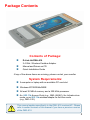
D-Link Air DWL-610 TM 2.4GHz Wireless Cardbus Adapter Manual version 1.02 Building Networks for People Contents Package Contents ................................................................................ 3 Introduction........................................................................................... 4 Wireless Basics ................................................................................... 6 Getting Started ..................................................................................... 8 Using the Configuration Utility ............................................................. 11 Networking Basics ............................................................................. 25 Troubleshooting .................................................................................. 38 Technical Specifications ..................................................................... 43 Warranty and Registration .................................................................. 45 Contacting Technical Support ............................................................. 50 2 Package Contents Contents of Package: n D-Link Air DWL-610 2.4 GHz Wireless Cardbus Adapter n n Manual and Drivers on CD Quick Installation Guide If any of the above items are missing, please contact your reseller. System Requirements: n A computer or laptop with an available PC card slot n Windows XP/2000/Me/98SE n At least 32 MB of memory and a 300 MHz processor n An 802.11b Access Point (e.g., DWL-900AP+) for Infrastructure mode, or an 802.11b wireless adapter for Ad-Hoc mode (e.g., DWL-510.) This manual applies specifically to the DWL-610 revision M1. Please refer to earlier versions of this manual if you have a previous version of the DWL-610. 3 Introduction The D-Link Air DWL-610 Wireless Cardbus Adapter is an 802.11b wireless adapter that supports high-speed wireless networking at home, at work or in public places. The DW L-610 is com patible with existing 802.11b devices such as the D-Link Air and AirPlus family of products including the DWL-510 and DWL-520+ Wireless PCI Adapters, the DI-614+ Wireless Router, DWL-900AP+ Wireless Access Point and the DWL-122 Wireless USB Adapter. The DWL-610 is an ideal way to connect your laptop computer to a Wireless Local Area Network (WLAN). After completing the steps outlined in the Quick Installation Guide (included in the package) you will have the ability to share information and resources, such as files and printers, and enjoy the freedom that wireless networking delivers. The DWL-610 comes with software drivers for the most popular Microsoft Windows operating systems and can be integrated into a larger network, running Windows XP, Windows 2000, Windows Me, or Windows 98SE in either Ad Hoc mode (without an Access Point or Router) or Infrastructure mode (with an Access Point or Router). The IEEE 802.11b Ethernet standard allows you to connect computers and 802.11b compatible devices at speeds up to 11Mbps, dependent upon the distance between wireless adapters, the configuration of your working environment, or the capabilities or limitations of your computer systems. 4 Features & Benefits n Provides a simple and inexpensive way to connect your laptop computer to a wireless network at home, at the office, or in public places n Fully compliant with the 802.11b standard and interoperable with all existing 802.11b-compliant devices n Quick and Easy Installation- The DWL-610 installs quickly and easily into a cardbus slot in a laptop computer. By following the simple steps outlined in the Quick Installation Guide, you can connect to an available wireless network in a matter of seconds n High Performance 32-bit Cardbus - The high capacity Cardbus interface utilized by the DWL-610 ensures optimal performance in transmitting a wireless signal within the laptop computer. n Provides high-speed wireless connection up to 11Mbps n Operates in the 2.4GHz frequency range n Maximum reliability, throughput and connectivity with automatic data rate switching n Provides a measure of security for the information transmitted over a wireless network with high data encryption at 64 or 128-bit WEP. n Supports infrastructure networks via an access point and peer-to-peer communication in ad-hoc mode n User-friendly configuration and diagnostic utilities LEDS LED stands for Light-Emitting Diode. Link: Solid green light indicates connection to the network ACT: Blinking amber light indicates activity on the network 5 Wireless Basics D-Link wireless products are based on industry standards to provide easy-to-use and compatible high-speed wireless connectivity within your home, business or public access wireless networks. D-Link wireless products will allow you access to the data you want, when and where you want it. You will be able to enjoy the freedom that wireless networking brings. A Wireless Local Area Network (WLAN) is a cellular computer network that transmits and receives data with radio signals instead of wires. WLANs are used increasingly in both home and office environments, and public areas such as airports, coffee shops and universities. Innovative ways to utilize WLAN technology are helping people to work and communicate more efficiently. Increased mobility and the absence of cabling and other fixed infrastructure have proven to be beneficial for many users. Wireless users can use the same applications they use on a wired network. Wireless adapter cards used on laptop and desktop systems support the same protocols as Ethernet adapter cards. People use WLAN technology for many different purposes: Mobility - Productivity increases when people have access to data in any location within the operating range of the WLAN. Management decisions based on real-time information can significantly improve worker efficiency. Low Implementation Costs – WLANs are easy to set up, manage, change and relocate. Networks that frequently change can benefit from WLANs ease of implementation. WLANs can operate in locations where installation of wiring may be impractical. Installation and Network Expansion - Installing a WLAN system can be fast and easy and can eliminate the need to pull cable through walls and ceilings. Wireless technology allows the network to go where wires cannot go - even outside the home or office. Scalability – WLANs can be configured in a variety of ways to meet the needs of specific applications and installations. Configurations are easily changed and range from peer-to-peer networks suitable for a small number of users to larger infrastructure networks to accommodate hundreds or thousands of users, depending on the number of wireless devices deployed. Inexpensive Solution - Wireless network devices are as competitively priced as conventional Ethernet network devices. 6 Wireless Basics (continued) The DWL-610 is compatible with 802.11b wireless products, which include: n D-Link AirPlus DWL-650+ 2.4GHz Wireless Cardbus Adapter used with laptop computers n D-Link Air DWL-510, D-Link AirPlus DWL-520+ 2.4GHz Wireless PCI cards used with desktop computers n D-Link AirPlus DWL-900AP+ Enhanced 2.4GHz Wireless Access Point n D-Link AirPlus DI-614+, DI-714P+ Enhanced 2.4GHz Wireless Broadband Routers Standards-Based Technology Based on the IEEE 802.11b standard, the DWL-610 is also interoperable with existing compatible 2.4GHz wireless technology with data transfer speeds of up to 11Mbps. Installation Considerations The D-Link Air DWL-610 lets you access your network, using a wireless connection, from virtually anywhere within its operating range. Keep in mind, however, that the number, thickness and location of walls, ceilings, or other objects that the wireless signals must pass through, may limit the range. Typical ranges vary depending on the types of materials and background RF (radio frequency) noise in your home or business. The key to maximizing wireless range is to follow these basic guidelines: 1 Keep the number of walls and ceilings between the DWL-610 and other network devices to a minimum - each wall or ceiling can reduce your D-Link Air Wireless product’s range from 3-90 feet (1-30 meters.)P o s i t i o n y o u r devices so that the number of walls or ceilings is minimized. 2 Be aware of the direct line between network devices. A wall that is 1.5 feet thick (.5 meters), at a 45-degree angle appears to be almost 3 feet (1 meter) thick. At a 2-degree angle it looks over 42 feet (14 meters) thick! Position devices so that the signal will travel straight through a wall or ceiling (instead of at an angle) for better reception. 3 Building Materials can impede the wireless signal - a solid metal door or aluminum studs may have a negative effect on range. Try to position wireless devices and computers with wireless adapters so that the signal passes through drywall or open doorways and not other materials. 4 Keep your product away (at least 3-6 feet or 1-2 meters) from electrical devices or appliances that generate RF noise. 7 Getting Started With its default settings, the DWL-610, when activated, will connect with other D-Link Air products, right out of the box. There are basically two modes of networking: nInfrastructure – using an Access Point or Router, such as the DI-614+ nAd-Hoc – directly connecting to another computer, for peer-topeer communication, using wireless network adapters on each computer, such as two or more DWL-610 wireless network adapters. On the following pages we will show you an example of an Infrastructure Network and an Ad-Hoc Network. An Infrastructure network contains an Access Point or Router. The Infrastructure Network example shown on the following page contains the following D-Link network devices (your existing network may be comprised of other devices): n A wireless Router - D-Link AirPlus DI-614+ n A laptop computer with a wireless adapter D-Link Air DWL-610 n A desktop computer with a wireless adapter D-Link Air DWL-510 n A Cable modem - D-Link DCM-200 8 Getting Started (continued) Setting up a Wireless Infrastructure Network 2 1 3 4 6 5 Please remember that D-Link Air wireless devices are pre-configured to connect together, right out of the box, with their default settings. For a typical wireless setup at home (as shown above), please do the following: You will need broadband Internet access (a Cable or DSL-subscriber line into your home or office) Consult with your Cable or DSL provider for proper installation of the modem Connect the Cable or DSL modem to your broadband router (see the Quick Installation Guide included with your router.) Install the D-Link Air DWL-510 wireless PCI adapter into an available PCI slot on your desktop computer. (See the Quick Installation Guide included with the DWL-510.) Install the D-Link Air DWL-610 wireless Cardbus adapter into a laptop computer. (See the Quick Installation Guide included with the DWL-610.) If you wish, you may connect a computer that is equipped with an Ethernet network adapter (such as a DFE-530TX+) to the router also. 9 Getting Started (continued) Setting up a Wireless Ad Hoc Network Desktop Install the Wireless PCI adapter(e.g., DWL-510) into the desktop computer. (See the Quick Installation Guide included with the product for installation instructions.) Install the DWL-610 wireless Cardbus adapter into a laptop computer. (See the Quick Installation Guide included with the product.) Set the wireless configuration for the adapters to Ad-Hoc mode, set the adapters to the same channel, and assign an IP Address to each computer on the Ad-Hoc network. (See Box below) IP Address When assigning IP Addresses to the computers on the network, please remember that the IP Address for each computer must be in the same IP Address range as all the computers in the network, and the subnet mask must be exactly the same for all the computers in the network. For example: If the first computer is assigned an IP Address of 192.168.0.2 with a Subnet Mask of 255.255.255.0, then the second computer can be assigned an IP Address of 192.168.0.3 with a Subnet Mask of 255.255.255.0, etc. IMPORTANT: If computers or other devices are assigned the same IP Address, one or more of the devices may not be visible on the network. 10 Using the Configuration Utility D-Link Air DWL-610 uses the Configuration Utility as the management software. The utility provides the user an easy interface to change any settings related to the wireless adapter. After you have completed the installation of the DWL-610 (refer to the Quick Installation Guide that came with your purchase) whenever you start the computer, the Configuration Utility starts automatically and the system tray icon is loaded in the toolbar (see illustration below*.) Clicking on the utility icon will start the Configuration Utility. Another way to start the Configuration Utility is to click on Start>Programs> D-Link Air>D-Link Air Utility. If you are using Windows XP, you can use either the Zero Configuration Utility or the D-Link Configuration Utility. To use the D-Link Configuration Utility with XP, right-click on the Wireless network icon in the taskbar in the lower right-hand corner of your computer screen. In the window that appears, select View Available Wireless Networks and click the Advanced button. The screen at right will appear. Select the Wireless Networks tab. test1 test2 Uncheck the box in the properties window that enables windows configuration. After you have done this, you can then use the D-Link Configuration Utility with XP by clicking on the D-Link Configuration Utility icon. *Config Utility icon in system tray If the icon does not display in the taskbar, then click on this icon on your desktop to open. 11 Using the Configuration Utility (continued) After clicking on the Configuration Utility icon, the Link Info screen will display the settings for the DWL-610: Status: Link Info Displays the MAC Address of the Access Point or Router to which the DWL-610 is associated SSID: The Service Set Identifier is the name assigned to the wireless network. The factory SSID setting is default. Frequency: 802.11b indicates that the DWL-610 is communicating in the 2.4GHz band. Wireless Mode: Either Infrastructure or Ad-Hoc will be displayed here. (Please see the Getting Started section in this manual for an explanation of these two modes.) Encryption: You can see if WEP (Wired Equivalent Privacy) is Enabled or Disabled here. Tx Rate: The default setting is Auto; Tx Rate settings are automatically determined for an optimal speed up to a maximum of 11Mbps. Channel: The default setting is Auto. The channel selection is automatically determined by the DWL-610. Signal Strength/Link Quality: Displays the Link Quality for the DWL-610 wireless connection to the access point. The Signal Strength represents the wireless signal between the access point and the DWL-610. The percentage coincides with the graphical bar Packet Count: Displays the statistics of the data packets that are transmitted and received. Rescan Button: Rescans for the strongest signal in your environment and associates with that Access Point or Router 12 Using the Configuration Utility (continued) SSID: Service Set Identifier is a name that identifies a wireless network. Access Points and wireless devices attempting to connect to a specific WLAN (Wireless Local Area Network) must use the same SSID. The default setting is default. Configuration Wireless Mode: Click on the pull-down menu; select from the following options: Infrastructure - connecting to the WLAN using an Access Point.(This is the default setting). Ad-Hoc – wireless mode used when connecting directly to a computer equipped with a wireless adapter in a peer-to-peer environment. IP Settings Data Encryption: Select Enabled or Disabled. Authentication: Choose one of the following modes: Open Authentication – the DWL-650 is visible to all devices on the network Shared Authentication – allows communication only with other devices with identical WEP settings WPA – Wi-Fi protected access. WPA-PSK – Wi-Fi protected access Pre-Shared Key. IEEE802.1X:. Enables or disables the use of 802.1X authentication Key Length: Select the key length and either ASCII (e.g., a word) or hexadecimal format. Keys 1-4: Select the default key Hexadecimal digits consist of the numbers 0-9 and the letters A-F ASCII (American Standard Code for Information Interchange) is a code for representing English letters as numbers from 0-127 IP Settings: When you click IP Settings in the Configuration window, the pop-up screen above will appear. Configure the IP Settings in this window. Click Apply to save changes. 13 Using the Configuration Utility (continued) Ad-Hoc Channel: Advanced All devices in the Ad Hoc network must be set to the same channel Profile IP Settings: You can Enable or Disable the IP Settings portion of your profile here. If you select Disable you will need to configure the IP Address information each time you connect to a network. If you select Enable you will maintain the same IP Address information each time you connect to a network. Power Mode: Disable -this default setting consumes the most power Enable - this setting consumes the least power Launch Utility on Startup: Select Enable or Disable Data Packet Parameter: Select the parameters here Fragmentation Threshold: This value should remain at its default setting of 2432. If you experience a high packet error rate, you may slightly increase your Fragmentation Threshold within the value range of 256 to 2432. Setting the Fragmentation Threshold too low may result in poor performance. RTS Threshold: This value should remain at its default setting of 2432. If inconsistent data flow is a problem, only a minor modification should be made. Click Apply if you have made any changes 14 Using the Configuration Utility (continued) Available Network: The top section of the window displays the Available Networks. Scroll up and down the list and highlight the network to which you wish to connect. Click on the Connect button. Profile: In the lower half of the screen, you can manage the profiles that you have created for the wireless network at home, at the office and in public places. Scroll up and down and highlight the profile that you wish to configure. You can Add or Remove a profile, or configure the Properties of the profile in order to connect with an available network. Refresh: Click on Refresh to get the most updated list of available networks. Site Survey Configure: Highlight an existing network and click Configure; the configuration window on the next page will appear. Advanced: Highlight a network; click Advanced and the screen on the next page will appear. Add: Click Add and the screen on the next page will appear. Remove: Highlight a network profile; click Remove to remove a network from the profile list. Properties: Highlight a network profile; click Properties and the screen on the next page will appear. Connect: Highlight a network profile; click Connect to connect to that network. Rescan: Click Rescan to rescan and connect to the strongest signal. 15 Using the Configuration Utility (continued) Site Survey > Add Advanced In this window you can select the type of network connection. Click OK to save the changes. If you clicked on Add, you can configure, in this window, all the properties of a profile that you wish to add to the network. If you clicked on Configuration or Properties you can configure, in this window, all the properties of a profile that already exists in the network. If you select WPA in the Authentication field, please see detailed instructions for configuring WPA on the following pages. If you choose to use the IEEE 802.1X feature, please see the detailed instructions on the following pages. Click OK to save the changes. 16 Using the Configuration Utility (continued) Site Survey > Configuration > 802.1X To use 802.1x and to configure its settings, please do the following: WPA IEEE 802.1X Select Enabled. Click Authentication Config Advanced Security Settings Select the EAP Type you want to use. Configure the information needed for authenticating. Inner Authentication Protocol. For an explanation of the terms shown in this window please see the following pages. Trusted CA List. Click OK. 17 Using the Configuration Utility (continued) 802.1x > Advanced Security Settings > EAP Types EAP Type Inner Authentication Protocol Information needed for Authenticating EAP-TLS Certificate User Name EAPMSCHAPv2 User Name Password Domain Name LEAP User Name Password EAP-TTLS PAP TTLS Identity User Name Password CHAP TTLS Identity User Name Password MSCHAP TTLS Identity User Name Password Domain Name MSCHAPv2 TTLS Identity User Name Password Domain Name 18 Using the Configuration Utility (continued) 802.1x > Advanced Security Settings > EAP Types (continued) EAP Type EAP-TTLS PEAP Inner Authentication Protocol Information needed for Authenticating EAP-MD5 TTLS Identity User Name Password EAPGeneric Token Card TTLS Identity User Name Password EAP-MSCHAPv2 TTLS Identity User Name Password Domain Name EAP-MD5 User Name Password EAP-MSCHAPv2 User Name Password Domain Name EAPGeneric Token Card User Name Password 802.1x > Advanced Security Settings > Definitions of Terms Validate Server Certificate: Check Validate Server Certificate to verify the identity of the authentication server based on its certificate when using EAP-TTLS, PEAP, and EAP-TLS. (This is checked by default.) Certain protocols, such as EAP-TTLS, PEAP, and EAP-TLS, allow you to verify the identity of the authentication server as the server verifies your identity. This is called mutual authentication. You can select trusted authentication server certificates using the Add button at the Trusted CA List (at the bottom of the Advanced Security Settings page). 19 Using the Configuration Utility (continued) 802.1x > Advanced Security Settings > Definitions of Terms (continued) Domain Name: Each server has a domain name that uniquely identifies it. That domain name is normally contained in the Subject CN field of the server certificate. A server domain name ends with the name of a larger administrative domain, to which the server belongs. TTLS Identity: EAP-TTLS has a unique feature that other protocols do not offer. Because it sets up an encrypted tunnel for your credentials, it is also able to pass your login name through that tunnel. That means that not only are your credentials secure from eavesdropping, but your identity is protected as well. Thus, with EAP-TTLS you have two identities: an inner one and an outer one. The inner identity is your actual user name. Your outer identity can be completely anonymous. Set your outer identity in the TTLS Identity field. Trusted CA List: The Trusted CA List allows you to configure which authentication servers you trust for the purpose of logging you into the network. Click Add at the Trusted CA List at the bottom of the Advanced Security Settings page. Select the Trusted CA that you want to add and click OK. 20 Using the Configuration Utility (continued) Authentication > WPA Select the available network to which you want to connect. Click Configure. Select WPA in the Authentication field. Click Authentication Config After you click Authentication Config, the Advanced Security Settings screen will appear. Complete the Advanced Security Settings configuration. Please see pages 17-20 of this manual to find out more about the Advanced Security Settings. 21 Using the Configuration Utility (continued) Select the available network to which you want to connect. Click Configure. WPA-PSK does not require a RADIUS Server in the network. Select WPA-PSK in the Authentication field. Click Authentication Config 22 Using the Configuration Utility (continued) Enter the WPA Passphrase. Click OK. The configuration is done. 23 Using the Configuration Utility (continued) About The ABOUT screen gives you the MAC Address, Utility Version and the Driver Version of the DWL-610. 24 Networking Basics Using the Network Setup Wizard in Windows XP In this section you will learn how to establish a network at home or work, using Microsoft Windows XP. Note: Please refer to websites such as http://www.homenethelp.com and http://www.microsoft.com/windows2000 for information about networking computers using Windows 2000, ME or 98SE. Go to Start>Control Panel>Network Connections Select Set up a home or small office network When this screen appears, click Next. 25 Networking Basics (continued) Please follow all the instructions in this window: Click Next In the following window, select the best description of your computer. If your computer connects to the internet through a gateway/router, select the second option as shown. Click Next 26 Networking Basics (continued) Enter a Computer description and a Computer name (optional.) Click Next Enter a Workgroup name. All computers on your network should have the same Workgroup name. Click Next 27 Networking Basics (continued) Please wait while the Network Setup Wizard applies the changes. When the changes are complete, click Next. Please wait while the Network Setup Wizard configures the computer. This may take a few minutes. 28 Networking Basics (continued) In the window below, select the option that fits your needs. In this example, Create a Network Setup Disk has been selected. You will run this disk on each of the computers on your network. Click Next. Insert a disk into the Floppy Disk Drive, in this case drive A. 29 Networking Basics (continued) Please read the information under Here’s how in the screen below. After you complete the Network Setup Wizard you will use the Network Setup Disk to run the Network Setup Wizard once on each of the computers on your network. To continue click Next. 30 Networking Basics (continued) Please read the information on this screen, then click Finish to complete the Network Setup Wizard. The new settings will take effect when you restart the computer. Click Yes to restart the computer. You have completed configuring this computer. Next, you will need to run the Network Setup Disk on all the other computers on your network. After running the Network Setup Disk on all your computers, your new wireless network will be ready to use. 31 Networking Basics (continued) Naming your Computer To name your computer, please follow these directions:In Windows XP: n Click Start (in the lower left corner of the screen) n Right-click on My Computer n Select Properties and click n Select the Computer Name Tab in the System Properties window. n You may enter a Computer Description if you wish; this field is optional. n To rename the computer and join a domain, Click Change. 32 Networking Basics (continued) Naming your Computer n In this window, enter the Computer name n Select Workgroup and enter the name of the Workgroup n All computers on your network must have the same Workgroup name. n Click OK Checking the IP Address in Windows XP The wireless adapter-equipped computers in your network must be in the same IP Address range (see Getting Started in this manual for a definition of IP Address Range.) To check on the IP Address of the adapter, please do the following: n Right-click on the Local Area Connection icon in the task bar n Click on Status 33 Networking Basics (continued) Checking the IP Address in Windows XP This window will appear. n Click the Support tab n Click Close Assigning a Static IP Address in Windows XP/2000 Note: Residential Gateways/Broadband Routers will automatically assign IP Addresses to the computers on the network, using DHCP (Dynamic Host Configuration Protocol) technology. If you are using a DHCP-capable Gateway/Router you will not need to assign Static IP Addresses. If you are not using a DHCP capable Gateway/Router, or you need to assign a Static IP Address, please follow these instructions: n Go to Start n Double-click on Control Panel 34 Networking Basics (continued) Assigning a Static IP Address in Windows XP/2000 n Double-click on Network Connections n Right-click on Local Area Connections n Double-click on Properties 35 Networking Basics (continued) Assigning a Static IP Address in Windows XP/2000 D-Link Air DWL-610 Wireless Cardbus Adapter n Click on Internet Protocol (TCP/IP) n Click Properties n In the window below, select Use the following IP address. Input your IP address and subnet mask. (The IP Addresses on your network must be within the same range. For example, if one computer has an IP Address of 192.168.0.2, the other computers should have IP Addresses that are sequential, like 192.168.0.3 and 192.168.0.4. The subnet mask must be the same for all the computers on the network.) IP Address: e.g., 192.168.0.2 Subnet Mask: 255.255.255.0 Default Gateway: Enter the LAN IP address of the wireless router. (D-Link wireless routers have a LAN IP address of 192.168.0.1) n Select Use the following DNS server address. Enter the LAN IP address of the Wireless Router. (D-Link wireless routers have a LAN IP address of 192.168.0.1) n Click OK You have completed the assignment of a Static IP Address. (You do not need to assign a Static IP Address if you have a DHCP-capable Gateway/Router.) 36 Networking Basics (continued) Checking the Wireless Connection by Pinging in Windows XP and 2000* n Go to Start > Run > type cmd. A window similar to this one will appear. Type ping xxx.xxx.xxx. xxx, where xxx is the IP Address of the Wireless Router or Access Point. A good wireless connection will show four replies from the Wireless Router or Acess Point, as shown. Checking the Wireless Connection by Pinging in Windows Me and 98* n Go to Start > Run > type command. A window similar to this will appear. Type ping xxx. xxx.xxx.xxx where xxx is the IP Address of the Wireless Router or Access Point. A good wireless connection will show four replies from the wireless router or access point, as shown. *You may be pinging different IP Addresses than the ones pictured here, however the procedure for pinging remains the same.) 37 Troubleshooting This chapter provides solutions to problems that can occur during the installation and operation of the DWL-610. Read the following descriptions if you are having problems. (The examples below are illustrated in Windows XP. If you have another operating system, these solutions will still apply although the appearance on your computer screen may differ.) 1. Check that the drivers for the DWL-610 are installed properly. n Go to Start > My Computer > Properties n Select the Hardware Tab n Click Device Manager 38 Troubleshooting (continued) n Double-click on Network Adapters n Right-click on D-Link Air DWL-610 Wireless Cardbus Adapter n Select Properties to check that the drivers are installed properly n Look under Device Status to check that the device is working properly n Click OK 39 Troubleshooting (continued) 2. I cannot connect to the access point or the wireless router. n Make sure that the SSID on the DWL-610 Cardbus adapter is exactly the same as the SSID on the Access Point or wireless router. n Move the DWL-610 and Access Point or Wireless router into the same room and then test the wireless connection. n Disable all security settings. (WEP, MAC Address Control, AES) n n Make sure that the Radio is not locked down to a different frequency n Turn off your Access Point and the computer with the DWL-610. Turn on the Access Point, and then turn on the computer with the DWL-610. Refresh the DWL-610 Utility 3. The DWL-610 Power and Link lights are not on. n Check to see if the DWL-610 Cardbus adapter is firmly inserted into the Cardbus slot of your laptop. 4. I forgot my Encryption key. n Reset the Access Point to its factory default settings and restore the DWL610 Wireless Cardbus Adapter to the factory default settings. (The default settings are listed in the Using the Configuration Utility section in this manual.) 5. The computer does not recognize the DWL-610 Cardbus Adapter. n Make sure that the DWL-610 Wireless Cardbus Adapter is properly seated in the laptop’s Cardbus slot. n If Windows does not detect the hardware upon insertion of the adapter, make sure to completely remove drivers that were previously loaded. To remove the drivers, do the following: 40 Troubleshooting (continued) A. Under Tools> select Folder Options… > select View > under Hidden files and folders > select Show hidden files and folders B. Uncheck Hide extension for known file types > click on Apply C. Search for the files DWL650.INF and DWL650.SYS. Remove these files from the INF and SYSTEM32 (DRIVERS) folders in the Windows directory. Note: Windows XP and Windows 2000 will rename .inf files that have not received WHQL certification into oem.inf files (e.g., oem1.inf.) 6. The computer with the DWL-610 installed is unable to connect to the wireless network and/or the Internet. n Check that the LED indicators for the broadband modem are indicating normal activity. If not, there may be a problem with the broadband connection. n Check that the LED indicators on the wireless router are functioning properly. If not, check that the AC power and Ethernet cables are firmly connected. n Check that the IP Address, subnet mask, gateway, and DNS settings are correctly entered for the network n In Infrastructure mode, make sure the same Service Set Identifier (SSID) is specified on the settings for the wireless clients and access points. The SSID factory default setting for the D-LinkAir and AirPlus products is default. (Double-click on the WLAN icon in the taskbar. The Link Info screen will display the SSID setting.) n In Ad-Hoc mode, both wireless clients will need to have the same SSID. Please note that it might be necessary to set up one client to establish a BSS (Basic Service Set) and wait briefly before setting up other clients. This prevents several clients from trying to establish a BSS at the same time, which can result in multiple singular BSSs being established, rather than a single BSS with multiple clients associated to it. 41 Troubleshooting (continued) n Check that the Network Connection for the wireless client is configured properly. Select AP (Infrastructure) when connecting to an access point and select Ad-Hoc mode when connecting without an access point. Doubleclick on the WLAN icon in the taskbar > click on Configuration to change the settings for the wireless adapter. n If Security is enabled, make sure that the correct encryption keys are entered on both the DWL-610 and the access point. Double-click on the WLAN icon in the taskbar > click Encryption. Check to see that the key selected is set to the same key as other devices on the network. 7. How can I troubleshoot distance issues using the DWL-610. n Move the DWL-610 and Access Point or Wireless router into the same room and then test the wireless connection. n Change the channel of the Access Point. n Move devices within the line of sight 42 Technical Specifications Standards n IEEE 802.11b Temperature n Operating: 32ºF to 131ºF (0ºC to 55ºC) n Storing: -4ºF to 167ºF (-20ºC to 75ºC) Humidity: n Operating: 10% - 90%, non-condensing n Storage: 5% - 95%, non-condensing Antenna Type: n Integrated Microstrip Antennas Emissions: n FCC part 15b Physical Dimensions: n L = 4.50 inches (114mm) n W = 2.25 inches (54mm) n H = .25 inches (6mm) Weight: n .095 lbs. (43g) Adapter Type: n PC Cardbus slot Warranty: n 1 Year System Requirements: n n n n Laptop with Cardbus Controller Windows XP/2000/Me/98SE At least 32MB of memory and a 300 MHz processor An 802.11b Access Point (e.g., DWL-900AP+) for Infrastructure mode; or an 802.11b wireless adapter (e.g., DWL-510) for Ad-Hoc mode 43 Technical Specifications (continued) Data Rates: n 1, 2, 5.5, 11Mbps (with Automatic Fallback) Operating Channels: n 1-11 United States (FCC) Encryption: n Supports 64-bit or 128-bit WEP encryption Frequency Range: n 2.4 – 2.4835 GHz, Direct Sequence Spread Spectrum Media Access Control: n CSMA/CA with ACK Transmit Output Power: n 16dBm (40mW) Receiver Sensitivity: Nominal Temp Range n -83dBm for 11Mbps @ 8% PER (Packet Error Rate) n -90dBm for 2Mbps @ 8% PER (Packet Error Rate) Modulation Techniques n n n n CCK (11Mbps) CCK (5.5Mbps) DQPSK (2Mbps) DBSK (1Mbps) Modulation: n Direct Sequence Spread Spectrum Range: n Indoors - up to 328 feet (100 meters)* 44 Wa r r a n t y a n d Re g i s t r at i o n Wichtige Sicherheitshinweise 1. Bitte lesen Sie sich diese Hinweise sorgfaltig durch. 2. Heben Sie diese Anleitung fur den spatern Gebrauch auf. 3. Vor jedem Reinigen ist das Gerat vom Stromnetz zu trennen. Vervenden Sie keine Flussig- oder Aerosolreiniger. Am besten dient ein angefeuchtetes Tuch zur Reinigung. 4. Um eine Beschadigung des Gerates zu vermeiden sollten Sie nur Zubehorteile verwenden, die vom Hersteller zugelassen sind. 5. Das Gerat is vor Feuchtigkeit zu schutzen. 6. Bei der Aufstellung des Gerates ist auf sichern Stand zu achten. Ein Kippen oder Fallen konnte Verletzungen hervorrufen. Verwenden Sie nur sichere Standorte und beachten Sie die Aufstellhinweise des Herstellers. 7. Die Beluftungsoffnungen dienen zur Luftzirkulation die das Gerat vor Uberhitzung schutzt. Sorgen Sie dafur, das diese Offnungen nicht abgedeckt werden. 8. Beachten Sie beim Anschlus an das Stromnetz die Anschlus werte. 9. Die Netzanschlus steckdose mus aus Grunden der elektrischen Sicherheit einen Schutzleiterkontakt haben. 10. Verlegen Sie die Netzanschlus leitung so, das niemand daruber fallen kann. Es sollete auch nichts auf der Leitung abgestellt werden. 11. Alle Hinweise und Warnungen die sich am Geraten befinden sind zu beachten. 12. Wird das Gerat uber einen langeren Zeitraum nicht benutzt, sollten Sie es vom Stromnetz trennen. Somit wird im Falle einer Uberspannung eine Beschadigung vermieden. 13. Durch die Luftungsoffnungen durfen niemals Gegenstande oder Flussigkeiten in das Gerat gelangen. Dies konnte einen Brand bzw. Elektrischen Schlag auslosen. 14. Offnen Sie niemals das Gerat. Das Gerat darf aus Grunden der elektrischen Sicherheit nur von authorisiertem Servicepersonal geoffnet werden. 15. Wenn folgende Situationen auftreten ist das Gerat vom Stromnetz zu trennen und von einer qualifizierten Servicestelle zu uberprufen: a Netzkabel oder Netzstecker sint beschadigt. b Flussigkeit ist in das Gerat eingedrungen. c Das Gerat war Feuchtigkeit ausgesetzt. d Wenn das Gerat nicht der Bedienungsanleitung ensprechend funktioniert oder Sie mit Hilfe dieser Anleitung keine Verbesserung erzielen. e Das Gerat ist gefallen und/oder das Gehause ist beschadigt. f Wenn das Gerat deutliche Anzeichen eines Defektes aufweist. 16. Bei Reparaturen durfen nur Orginalersatzteile bzw. den Orginalteilen entsprechende Teile verwendet werden. Der Einsatz von ungeeigneten Ersatzteilen kann eine weitere Beschadigung hervorrufen. 17. Wenden Sie sich mit allen Fragen die Service und Repartur betreffen an Ihren Servicepartner. Somit stellen Sie die Betriebssicherheit des Gerates sicher. Limited Warranty Hardware: D-Lin k wa r r an t s it s h a r dwa re pr odu ct s to be free from defect s in wor km a n sh ip an d m a ter ia ls, u nder n orm a l u se a n d ser vice, for t he followin g per iods m ea su red from da t e of pu rch a se from D-Lin k or it s Au t h or ized Reseller : P rodu ct Type Wa r r an t y P er iod Com plet e produ ct s On e year Spa r e pa r t s a n d spar e kit s 90 da ys Th e one-year per iod of war r a nt y on com plet e produ ct s a pplies on con dit ion t h a t t he pr oduct ’s Regist r a t ion Ca r d is filled ou t a nd r etu r ned to a D-Lin k office with in n in ety (90) da ys of pu r ch a se. A list of D-Lin k offices is provided a t t h e ba ck of th is m a n u a l, togeth er wit h a copy of t h e Regist r a t ion Ca r d. F a ilin g such t im ely r egistr a t ion of pu rch a se, t h e wa rr a n t y per iod sh a ll be lim ited to 90 da ys. If t h e produ ct proves defect ive wit h in t he a pplica ble wa rr a n t y per iod, D-Lin k will provide repa ir or r epla cem ent of t he produ ct. D-Lin k sh a ll h a ve t he sole discr et ion whet her to r epa ir or r epla ce, a n d r epla cem ent produ ct m a y be new or recon dit ion ed. Replacem en t pr oduct sh a ll be of equ iva lent or bet t er specifica t ion s, rela t ive to th e defect ive produ ct, bu t need not be iden t ica l. An y produ ct or pa r t r epa ired by D-Lin k pu r su an t to t h is wa rr a n t y sh a ll h a ve a war ra n t y per iod of not less th a n 90 da ys, fr om da te of su ch repa ir , irr espect ive of a n y ear lier expir a t ion of or igin a l war r a n t y per iod. Wh en D-Lin k pr ovides repla cem en t, t hen th e defect ive pr oduct becom es t h e proper t y of D-Lin k. Wa r r an t y service m a y be obt a in ed by con t a ct in g a D-Link office wit h in t h e a pplica ble wa r r an t y per iod, a n d request in g a Ret ur n Ma t er ia l Au th or iza t ion (RMA) n u m ber. If a Registr a t ion Car d for t h e pr oduct in quest ion h a s not been ret ur ned to D-Link, t hen a pr oof of pu rch a se (such a s a copy of t h e da t ed pur ch a se invoice) m u st be provided. If P u rch a ser’s cir cu m st a nces requ ire specia l h a n dlin g of wa rr a n t y cor rect ion, th en a t t h e t im e of request ing RMA n um ber , P ur ch a ser m a y a lso propose specia l procedur e a s m a y be su ita ble to th e ca se. Aft er a n RMA nu m ber is issued, t h e defect ive pr oduct m u st be pa cka ged secur ely in t he or igin a l or ot her su it a ble sh ippin g pa ckage to ensu re th a t it will n ot be da m a ged in tr a n sit, a n d t he RMA n u m ber m u st be prom in en t ly m a r ked on th e ou t side of t he pa cka ge. The pa cka ge m ust be m a iled or ot her wise sh ipped to D-Link wit h a ll cost s of m a ilin g/sh ippin g/in su r a nce prepa id; D-Lin k will or din a r ily reim bu r se P u rch a ser for m a iling/sh ippin g/in sur a n ce expen ses incu rr ed for ret u rn of defect ive product in accor da n ce wit h t h is wa r r a nt y. D-Link sh a ll n ever be responsible for a n y soft wa re, fir m wa re, in form a t ion, or m em or y da t a of P u r ch a ser con t a in ed in, stored on , or in tegr a ted wit h a n y produ ct ret u rn ed to D-Lin k pu r su a n t to t h is war r a n ty. An y pa cka ge r etu r ned to D-Link wit hou t an RMA n um ber will be reject ed a n d sh ipped ba ck t o P u rch a ser a t P u r ch a ser ’s expen se, a n d D-Lin k reser ves t he r igh t in such a ca se to levy a r ea son able h a n dlin g ch a r ge in a ddit ion m a ilin g or sh ippin g cost s. Software: Wa r r an t y ser vice for soft wa re pr odu ct s m a y be obt a ined by cont a ct in g a D-Lin k office with in th e a pplica ble wa rr a n t y per iod. A list of D-Lin k offices is provided at t he ba ck of t h is m a nu a l, t ogeth er wit h a copy of th e Registr a t ion Ca r d. If a Regist r a t ion Ca r d for th e produ ct in quest ion h a s n ot been r et ur ned t o a D-Lin k office, t hen a pr oof of pu rch a se (su ch as a copy of t h e da ted pu r ch a se in voice) m u st be pr ovided when request in g war r a n ty ser vice. The t erm "pu r ch a se" in t h is soft wa re wa rr an t y r efer s t o t he pur ch a se t r a n sact ion a n d r esu lt in g licen ce t o u se su ch soft wa re. D-Lin k wa rr a n t s t h a t it s softwa r e produ ct s will per for m in su bst an t ia l con form a nce with t he a pplica ble produ ct docum en t a t ion pr ovided by D-Lin k wit h such soft wa re product , for a per iod of n in et y (90) da ys from t he da te of pu r ch ase fr om D-Link or it s Aut h or ized Reseller . D-Link war r an t s t h e m agnet ic m edia , on wh ich D-Lin k provides it s soft wa re pr odu ct , a ga in st fa ilur e du r in g t he sa m e wa r r a n t y per iod. Th is wa r r an t y a pplies to pur ch ased softwa r e, a n d to r epla cem en t softwa r e pr ovided by D-Lin k pu r su a n t t o t h is war r a n t y, bu t sh a ll not apply t o a n y u pda te or r epla cem en t wh ich m a y be provided for down loa d via th e In tern et, or to a ny u pda t e wh ich m a y oth er wise be pr ovided fr ee of ch ar ge. D-Lin k’s sole obliga t ion u n der t h is soft war e wa r r an t y sh a ll be t o repla ce a n y defect ive soft wa r e pr odu ct wit h produ ct wh ich su bst a n t ia lly con for m s to D-Link’s a pplica ble produ ct docum en t a t ion . P u rch a ser a ssum es respon sibility for t he select ion of a ppr opr ia te a pplica t ion a n d system /pla t form soft wa re a n d a ssocia ted refer en ce m a ter ia ls. D-Link m a kes n o wa r r a n t y t h a t it s soft wa re pr odu ct s will work in com bin a t ion with an y h a r dwa re, or a n y a pplica t ion or syst em /pla t form soft wa re produ ct pr ovided by a n y t h ir d pa r t y, except in g on ly su ch produ ct s a s a re expr essly repr esent ed, in D-Link’s a pplica ble produ ct docum en t a t ion a s bein g com pa t ible. D-Link’s obliga t ion u n der t h is war r an t y sh a ll be a rea son a ble effor t to pr ovide com pa t ibilit y, bu t D-Lin k sh a ll h a ve n o obliga t ion to provide com pa t ibilit y when th er e is fa u lt in t he t h ir d-pa r t y h a r dwa re or soft wa re. D-Link m a kes n o wa r r a n t y t h a t oper a t ion of it s soft wa re pr oduct s will be u n in t err u pt ed or a bsolu tely err or -fr ee, a n d n o wa rr a n t y th a t a ll defect s in t h e soft war e produ ct, wit h in or with ou t t he scope of D-Lin k’s a pplica ble produ ct docu m en t a t ion , will be corr ected. LIMITATION OF WARRANTIES IF TH E D-LINK P RODUCT DOE S NOT OP E RATE AS WARRANTE D ABOVE , TH E CUSTOMER’S SOLE RE ME DY SH ALL BE , AT D-LINK’S OP TION, REP AIR OR RE P LACE MENT. TH E F ORE GOING WARRANTIE S AND RE ME DIE S ARE E XCLUSIVE AND ARE IN LIEU OF ALL OTH E R WARRANTIE S, E XP RE SSE D OR IMP LIE D, E ITH E R IN F ACT OR BY OP E RATION OF LAW, STATUTORY OR OTHE RWISE , INCLUDING WARRANTIE S OF ME RCH ANTABILITY AND F ITNE SS F OR A P ARTICULAR P URP OSE . D-LINK NE ITH E R ASSUME S NOR AUTH ORIZE S ANY OTH E R P E RSON TO ASSUME F OR IT ANY OTH E R LIABILITY IN CONNE CTION WITH TH E SALE , INSTALLATION MAINTE NANCE OR USE OF D-LINK’S P RODUCTS. D-LINK SH ALL NOT BE LIABLE UNDE R TH IS WARRANTY IF ITS TE STING AND E XAMINATION DISCLOSE TH AT TH E ALLE GE D DE F E CT IN TH E P RODUCT DOE S NOT E XIST OR WAS CAUSE D BY TH E CUSTOME R’S OR ANY TH IRD P E RSON’S MISUSE , NE GLE CT, IMP ROP E R INSTALLATION OR TE STING, UNAUTH ORIZE D ATTE MP TS TO RE P AIR, OR ANY OTH E R CAUSE BE YOND TH E RANGE OF TH E INTENDE D USE, OR BY ACCIDE NT, F IRE , LIGH TNING OR OTH E R H AZARD. LIMITATION OF LIABILITY IN NO E VE NT WILL D-LINK BE LIABLE F OR ANY DAMAGE S, INCLUDING LOSS OF DATA, LOSS OF P ROF ITS, COST OF COVE R OR OTH E R INCIDE NTAL, CONSE QUE NTIAL OR INDIRE CT DAMAGE S ARISING OUT TH E INSTALLATION, MAINTE NANCE , USE , P E RF ORMANCE, F AILURE OR INTE RRUP TION OF A D- LINK P RODUCT, H OWEVE R CAUSE D AND ON ANY TH E ORY OF LIABILITY. TH IS LIMITATION WILL AP P LY E VEN IF DLINK H AS BE EN ADVISE D OF TH E P OSSIBILITY OF SUCH DAMAGE . IF YOU P URCH ASE D A D-LINK P RODUCT IN TH E UNITE D STATE S, SOME STATE S DO NOT ALLOW TH E LIMITATION OR E XCLUSION OF LIABILITY F OR INCIDENTAL OR CONSE QUENTIAL DAMAGE S, SO TH E ABOVE LIMITATION MAY NOT AP P LY TO YOU. D-Link Offices for Registration and Warranty Service Th e produ ct’s Registr a t ion Ca r d, pr ovided a t t he back of t h is m anu a l, m u st be sen t t o a D-Link office. To obt a in a n RMA nu m ber for wa r r a n t y ser vice a s to a h a r dwa r e produ ct, or t o obt a in war r an t y ser vice a s to a soft wa re produ ct , con t a ct th e D-Lin k office nea rest you. An a ddr esses/telephone/fa x list of D-Link offices is provided in t he ba ck of th is m a n u a l. Trademarks Copyright 2002 D-Link Corporation. Contents subject to change without prior notice. D-Link is a registered trademark of D-Link Corporation/D-Link Systems, Inc. All other trademarks belong to their respective proprietors. Copyright Statement No part of this publication may be reproduced in any form or by any means or used to make any derivative such as translation, transformation, or adaptation without permission from D-Link Corporation/D-Link Systems Inc., as stipulated by the United States Copyright Act of 1976 Federal Communication Commission Interference Statement This equipment has been tested and found to comply with the limits for a Class B digital device, pursuant to Part 15 of the FCC Rules. These limits are designed to provide reasonable protection against harmful interference in a residential installation. This equipment generates, uses and can radiate radio frequency energy and, if not installed and used in accordance with the instructions, may cause harmful interference to radio communications. However, there is no guarantee that interference will not occur in a particular installation. If this equipment does cause harmful interference to radio or television reception, which can be determined by turning the equipment off and on, the user is encouraged to try to correct the interference by one of the following measures: - Reorient or relocate the receiving antenna. - Increase the separation between the equipment and receiver. - Connect the equipment into an outlet on a circuit different from that to which the receiver is connected. - Consult the dealer or an experienced radio/TV technician for help. This device complies with Part 15 of the FCC Rules. Operation is subject to the following two conditions: (1) This device may not cause harmful interference, and (2) this device must accept any interference received, including interference that may cause undesired operation. FCC Caution: Any changes or modifications not expressly approved by the party responsible for compliance could void the user’s authority to operate this equipment. IMPORTANT NOTE: FCC Radiation Exposure Statement: This equipment complies with FCC radiation exposure limits set forth for an uncontrolled environment. This equipment should be installed and operated with minimum distance 20cm between the radiator & your body. This transmitter must not be co-located or operating in conjunction with any other antenna or transmitter. CE Mark Warning This is a Class A product. In a domestic environment this product may cause radio interference in which case the user may be required to take adequate measures. Warnung! Dies ist ein Produkt der Klasse A. Im Wohnbereich kann dieses Produkt Funkstoerungen verursachen. In diesem Fall kann vom Benutzer verlangt werden, angemessene Massnahmen zu ergreifen. Precaucion! Este es un producto de Clase A. En un entorno domestico, puede causar interferencias de radio, en cuyo case, puede requerirse al usuario para que adopte las medidas adecuadas. Attention! Ceci est un produit de classe A. Dans un environnement domestique, ce produit pourrait causer des interferences radio, auquel cas l‘ utilisateur devrait prendre les mesures adequates. Attenzione! Il presente prodotto appartiene alla classe A. Se utilizzato in ambiente domestico il prodotto puo causare interferenze radio, nel cui caso e possibile che l‘ utente debba assumere provvedimenti adeguati. BSMI Warning Offices Australia D-Link Australasia Unit 16, 390 Eastern Valley Way, Roseville, NSW 2069 Australia TEL: 61-2-9417-7100 FAX: 61-2-9417-1077 TOLL FREE (Australia): 1800-177100 TOLL FREE (New Zealand): 0800-900900 URL: www.dlink.com.au E-MAIL: [email protected] & [email protected] Level 1, 434 St. Kilda Road, Melbourne, Victoria 3004 Australia TEL: 61-3-9281-3232 FAX: 61-3-9281-3229 MOBILE: 0412-660-064 Canada D-Link Canada 2180 Winston Park Drive, Oakville, Ontario, L6H 5W1 Canada TEL: 1-905-829-5033 FAX: 1-905-829-5095 BBS: 1-965-279-8732 TOLL FREE: 1-800-354-6522 URL: www.dlink.ca FTP: ftp.dlinknet.com E-MAIL: [email protected] Chile D-Link South America Isidora Goyeechea 2934 of 702, Las Condes, Santiago, Chile, S. A. TEL: 56-2-232-3185 FAX: 56-2-232-0923 URL: www.dlink.cl E-MAIL: [email protected] & [email protected] China D-Link China 2F, Sigma Building, 49 Zhichun Road, Haidan District, 100080 Beijing, China TEL: 86-10-88097777 FAX: 86-10-88096789 URL: www.dlink.com.cn E-MAIL: [email protected] Denmark D-Link Denmark Naverland 2, DK-2600 Glostrup, Copenhagen, Denmark TEL: 45-43-969040 FAX:45-43-424347 URL: www.dlink.dk E-MAIL: [email protected] Egypt D-Link Middle East 7 Assem Ebn Sabet Street, Heliopolis, Cairo, Egypt TEL: 20-2-635-6176 FAX: 20-2-635-6192 URL: www.dlink-me.com E-MAIL: [email protected] & [email protected] Finland D-Link Finland Thlli-ja Pakkahuone Katajanokanlaituri 5, FIN 00160 Helsinki TEL: 358-9-622-91660 FAX: 358-9-622-91661 URL: www.dlink-fi.com France D-Link France Le Florilege #2, Allee de la Fresnerie, 78330 Fontenay le Fleury, France TEL: 33-1-3023-8688 FAX: 33-1-3023-8689 URL: www.dlink-france.fr E-MAIL: [email protected] Germany D-Link Central Europe/D-Link Deutschland GmbH Schwalbacher Strasse 74, D-65760 Eschborn, Germany TEL: 49-6196-77990 FAX: 49-6196-7799300 URL: www.dlink.de BBS: 49-(0) 6192-971199 (analog) BBS: 49-(0) 6192-971198 (ISDN) INFO: 00800-7250-0000 (toll free) HELP: 00800-7250-4000 (toll free) REPAIR: 00800-7250-8000 E-MAIL: [email protected] India D-Link India Plot No.5, Kurla-Bandra Complex Rd., Off Cst Rd., Santacruz (E), Bombay, 400 098 India TEL: 91-22-652-6696 FAX: 91-22-652-8914 URL: www.dlink-india.com E-MAIL: [email protected] Italy D-Link Mediterraneo Srl/D-Link Italia Via Nino Bonnet n. 6/b, 20154, Milano, Italy TEL: 39-02-2900-0676 FAX: 39-02-2900-1723 URL: www.dlink.it E-MAIL: [email protected] Japan D-Link Japan 10F, 8-8-15 Nishi-Gotanda, Shinagawa-ku, Tokyo 141, Japan TEL: 81-3-5434-9678 FAX: 81-3-5434-9868 URL: www.d-link.co.jp E -MAIL: k ida @d-lin k.co.jp Netherlands D-Link Benelux Fellenoord 1305611 ZB, Eindhoven, the Netherlands TEL: 31-40-2668713 FAX: 31-40-2668666 URL: www.d-link-benelux.n Norway D-Link Norway Waldemar Thranesgt. 77, 0175 Oslo, Norway TEL: 47-22-991890 FAX: 47-22-207039 Russia D-Link Russia Michurinski Prospekt 49, 117607 Moscow, Russia TEL: 7-095-737-3389 & 7-095-737-3492 FAX: 7-095-737-3390 URL: www.dlink.ru E-MAIL: [email protected] Singapore D-Link International 1 International Business Park, #03-12 The Synergy, Singapore 609917 TEL: 65-774-6233 FAX: 65-774-6322 E-MAIL: [email protected] URL: www.dlink-intl.com South Africa D-Link South Africa 102 106 Witchhazel Avenue, Einstein Park 2, Block B, Highveld Technopark, Centurion, South Africa TEL: 27 (0) 12-665-2165 FAX: 27 (0) 12-665-2186 URL: www.d-link.co.za E-MAIL: [email protected] Spain D-Link Iberia C/Sabino De Arana, 56 Bajos, 08028 Barcelona, Spain TEL: 34 93 4090770 FAX: 34 93 4910795 URL: www.dlinkiberia.es E-MAIL: [email protected] Sweden D-Link Sweden P. O. Box 15036, S-167 15 Bromma, Sweden TEL: 46-(0) 8-564-61900 FAX: 46-(0) 8-564-61901 E-MAIL: [email protected] URL: www.dlink.se Taiwan D-Link Taiwan 2F, No. 119 Pao-Chung Rd, Hsin-Tien, Taipei, Taiwan TEL: 886-2-2910-2626 FAX: 886-2-2910-1515 URL: www.dlinktw.com.tw E-MAIL: [email protected] Turkey D-Link Middle East Deniz Bilgisayar, Buyukdere Cad. Naci Kasim Sk., No. 5 Mecidiyekoy, Istanbul, Turkey TEL: 90-212-213-3400 FAX: 90-212-213-3420 E-MAIL: [email protected] U.A.E. D-Link Middle East CHS Aptec (Dubai), P.O. Box 33550 Dubai U.A.E. TEL: 971-4-366-885 FAX: 971-4-355-941 E-MAIL: [email protected] U.K. D-Link Europe 4th Floor, Merit House, Edgware Road, Colindale, London NW9 5AB United Kingdom TEL: 44 (0) 20-8731-5555 FAX: 44 (0) 20-8731-5511 BBS: 44 (0) 181-235-5511 URL: www.dlink.co.uk E-MAIL: [email protected] U.S.A. D-Link U.S.A. 17575 Mt. Herrmann Street Fountain Valley, CA. 92708 TEL: 1-714-885-6000 FAX: 1-866-743-4905 URL: www.dlink.com E-MAIL: [email protected] & [email protected]