1
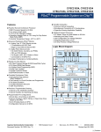
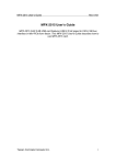
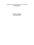
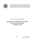
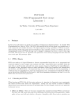
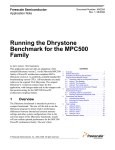
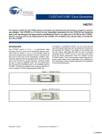
User Interface - Keypad Scan, PSoC® Style AN2034 Author: Dave Van Ess Associated Project: Yes Associated Part Family: CY8C20x34, CY8C21x23, CY8C21x34 CY8C23x33, CY8C24x23A, CY8C24x94 CY8C27x43, CY8C29x66 GET FREE SAMPLES HERE Software Version: PSoC Designer™ 5.0 Associated Application Notes: AN2354 Application Note Abstract X–Y matrix keypads are an inexpensive interface enabling interaction with microcontroller-based products. This application note shows how the PSoC® microcontroller’s unique I/O structure can build a keypad scan routine that is fast, uses minimal RAM resources, and operates in a polled or interrupt mode. A function callable by either ‘C’ or assembly language is also presented. Introduction An X-Y keypad enables use of N column lines and M row lines to detect switch closures for N * M switches. For this application note, a keypad is defined as an X-Y matrix where only one key is pressed at a time, as opposed to a keyboard where simultaneous key closures are the norm ([Ctrl] [Shift] [Delete]). This keypad definition is valid for telephones, calculators, security entry kiosks, or other products where only one key is pressed at a time. This application relies on PSoC General Purpose Input Output (GPIO). Closure of switch [i, j] (column i, row j) enables current flow from row j to column i. This keypad requires only eight connections to the MCU. The 16 diodes can detect multiple key closures. However, because PSoC microcontroller reduces the cost of external components such as op-amps, filters, and DACs, using 16 diodes is not a good idea. Well known techniques have been developed to detect multiple key presses without diodes. Figure 2 shows the keypad without diodes. Figure 2. The Keypad you can Afford C0 Rows and Columns C3 [0,0] [1,0] [2,0] [3,0] [0,1] [1,1] [2,1] [3,1] [0,2] [1,2] [2,2] [3,2] [0,3] [1,3] [2,3] [3,3] R1 Figure 1. 4-Column by 4-Row Keypad C1 C2 R0 This application note uses C columns and R rows. Figure 1 shows an example of such a keypad: C0 C1 C2 C3 R2 R0 [0,0] [1,0] [2,0] [3,0] [0,1] [1,1] [2,1] [3,1] [0,2] [1,2] [2,2] [3,2] [0,3] [1,3] [2,3] [3,3] R3 R1 R2 R3 The standard algorithm for reading a keypad is to individually drive each row and sample the status of all columns. Correctly combining all this information enables detection of at least two simultaneous switch closures. The hardware cost is less but there is software overhead required to scan all four rows, read column status, and condense this information into an answer. To develop a keypad scan that is low in both hardware and software resources, limit its operation to single-key presses. January 16, 2009 Document No. 001-40409 Rev. *A 1 [+] Feedback AN2034 PSOC General Purpose IO Figure 4 shows implementation of a keypad scan. To detect single-switch closures, use the following algorithm: Figure 4. PSoC Architecture for Keypad Scan Drive all rows simultaneously and read the columns. PX.0 Drive all columns simultaneously and read the rows. PX.1 Condense this data to determine switch-closure status. PX.2 C1 C2 C3 R0 R1 R2 PX.3 The structure of the general purpose of each pin simplifies this bipolar use of rows and columns. Each pin has a digital driver that can be set up to be: C0 PX.4 R3 PX.5 PX.6 PX.7 Strong drive to VDD and a pull down resistor to Vss. Strong drive to Vss and a pull up resistor to VDD. High Impedance For this, press example switch [2,1] (column 2, row 1). The algorithm reads the keypad in six steps. 1. Output b00001111 to the port. This drives all the rows high, leaving the columns passively pulled down. 2. Read the port. The driven pins 0 through 3 remain high and because the switch [2,1] is closed, pin 6 is now high. The value read is b01001111. 3. Output b11110000 to the port. This drives all the columns high, leaving the rows passively pulled down. 4. Read the port. The driven pins 4 through 7 remain high and because the switch [2,1] is closed, pin 1 is now high. The value read is b11110010. 5. “Anding” the result of step 2 and step 4 results in the answer b01000010. 6. The upper 4 bits decode as column 2 and the lower 4 bits decode as row 1. This is a match with the closed switch. Strong drive to either VDD or Vss Use the pull down drive mode in the keypad scan routine, as shown in Figure 3. Because it is also the default condition for each pin at initial startup, there is no requirement for special port configuration. Figure 3. GPIO Set For Pull Down Mode VDD Dout pin D in 5.6 k Vss A subroutine that implements this algorithm is shown in example Code 1. It enables the reading of a four row by four column keypad connected to port 1. It is found in “Keypad.asm,” located in the project file associated with this application note. This subroutine uses eight instructions, 15 bytes of program memory bytes, and 57CPU cycles. January 16, 2009 Document No. 001-40409 Rev. *A 2 [+] Feedback AN2034 Code 1: Subroutine for Reading Keypad Using the Output ;----------------------------------------; Keypad.asm ; ; This routine reads a 4 column by 4 row ; keypad on port1. The status of key ; closures is returned in A. ; ; P1.4 P1.5 P1.6 P1.7 ; C0 C1 C2 C3 ; P1.0 R0 --+----+----+----+; | | | | ; P1.1 R1 --+----+----+----+; | | | | ; P1.2 R2 --+----+----+----+; | | | | ; P1.3 R3 --+----+----+----+; The output of the function bReadKeypad is a single byte that shows the status of key closure of the keypad. It is translated and decoded as follows: ;-----------------------------------------export bReadKeypad export _bReadKeypad include "m8c.inc" Another scheme is to use a lookup table to decode this data. The advantage is that the table stores the formatted data. Different programmers could be working on the same project and each use their own table to decode the keypad when they are required to read it. bReadKeypad: _bReadKeypad: mov reg[PRT1DR], f0h mov X,SP mov A, reg[PRT1DR] mov reg[PRT1DR], 0fh push A ;store mov A, reg[PRT1DR] and [X], A pop A ret ;drive columns ;read rows ;drive rows row info on stack ;Read Columns ;combine them No bits are set if no key is pressed. A single bit in the upper nibble and a single bit in the lower nibble are set for a single-key press. Any other condition is a multiple-key closure and is defined as not valid. These rules can be decoded with discrete conditional code that breaks up the byte into two nibbles to determine row and column information. Use this information to determine which key, if any, was pressed. This results in a complex set of rules and is tedious. The project file associated with this application note uses such a table to decode the key closures. A block diagram of the project is shown in Figure 5. Figure 5. Block Diagram for the Keypad Project C0 C1 C2 1 The C header shown in example Code 2 can be found in “Keypad.h.” It makes the subroutine shown in example Code 1 a ‘C’ callable function. Code 2. C Header Example // Create a pragma to support // proper argument and return // value passing #pragma fastcall bReadKeypad extern BYTE bReadKeypad(void); January 16, 2009 4 2 5 3 R0 6 R1 7 8 9 R2 * 0 # R3 P1.4 P0.6 P1.5 P0.5 P1.6 P1.0 PSoC MCU P0.4 P0.3 P1.1 P0.2 P1.2 P0.1 P1.3 P0.0 Vdd(common anode) a cathode b cathode c cathode a b f g d cathode e cathode e f cathode g cathode c d MAN71A For this project, set the drives for the port 1 pins to the Pull Down mode (default) and the port 0 pins to either the Pull Down or Strong mode. The keypad is scanned and the appropriate bits are set on the output port to turn on the desired LED segments. This display is a single digit 7-segment common anode LED display. Any particular segment is lit when its cathode is pulled low. As an example, all output pins low result in an “8” being displayed. All output pins high result in a blank display. Document No. 001-40409 Rev. *A 3 [+] Feedback AN2034 Example Code 3 is the main function that implements the design in Figure 5 on page 3. Code 3. Keypad Project Implemented ;----------------------------------------; This program reads the keypad ; at port 1 and control the LEDs ; on port0. ; ; Copyright (c) ; Cypress Semiconductor 2002-2008. ; All Rights Reserved. ;-----------------------------------------include "m8c.inc" export _main _main: loop: call index mov jmp bReadKeypad KeyToLED reg[PRT0DR], A loop Debouncing solutions are specific to each system’s program structure and switch selection. However, debouncing is simple; it requires two sequential keypad scans to agree for the scan to be valid. Interrupt Driven Keypad Scans Execute the following steps for an interrupt-instigated key scan: Configure the lower four (row) pins to be I/O interrupts on a rising edge. Set the upper four (column) pins high. Write an interrupt handler that calls bReadKeypad. Enable the GPIO interrupt. The row pins stay low until a key press connects a column to a row causing an interrupt. ret xxh: equ 30h Debouncing ;illegal character “E” .Literal KeyToLED: db 7fh,xxh,xxh,xxh,xxh,xxh,xxh,xxh db xxh,xxh,xxh,xxh,xxh,xxh,xxh,xxh db xxh,4fh,4ch,xxh,0fh,xxh,xxh,xxh db 78h,xxh,xxh,xxh,xxh,xxh,xxh,xxh db xxh,12h,24h,xxh,00h,xxh,xxh,xxh db 01h,xxh,xxh,xxh,xxh,xxh,xxh,xxh db xxh,xxh,xxh,xxh,xxh,xxh,xxh,xxh db xxh,xxh,xxh,xxh,xxh,xxh,xxh,xxh db xxh,06h,20h,xxh,04h,xxh,xxh,xxh db 18h,xxh,xxh,xxh,xxh,xxh,xxh,xxh db xxh,xxh,xxh,xxh,xxh,xxh,xxh,xxh db xxh,xxh,xxh,xxh,xxh,xxh,xxh,xxh db xxh,xxh,xxh,xxh,xxh,xxh,xxh,xxh db xxh,xxh,xxh,xxh,xxh,xxh,xxh,xxh db xxh,xxh,xxh,xxh,xxh,xxh,xxh,xxh db xxh,xxh,xxh,xxh,xxh,xxh,xxh,xxh .EndLiteral One possible application is a security gate keypad reader where the MCU is placed in the power-saving-sleep mode. When someone presses a key, the processor wakes up and decodes the user’s input. After finishing, the MCU can put itself back to sleep. For more information about sleep mode operation please refer to application note AN2354. Summary The PSoC microcontroller GPIO structure is ideal for fast keypad scans. The “index” instruction enables simple translation key presses to a user’s desired format. The GPIO to interrupts makes for an interrupt-driven keypad scan. The “.Literal” and “.EndLiteral” macros are used to disable the compiler’s code compression algorithms so that the literal information in the KeyToLED table is not compressed. This code can also be found in the project associated with this application note. The table makes for a simple translation from key press to displayed character. Develop your own table for a particular application. January 16, 2009 Document No. 001-40409 Rev. *A 4 [+] Feedback AN2034 Document History Document Title: User Interface – Keypad Scan, PSoC® Style Document Number: 001-40409 Revision ** *A ECN 1532004 2640952 Orig. of Change OGNE JVY Submission Date 10/02/07 01/20/09 Description of Change New publication of existing application note. Updated content. Added part numbers CY8C20x34, CY8C21x23, CY8C21x34, CY8C23x33, CY8C24x23A, CY8C24x94, CY8C27x43, and CY8C29x66. In March of 2007, Cypress recataloged all of its Application Notes using a new documentation number and revision code. This new documentation number and revision code (001-xxxxx, beginning with rev. **), located in the footer of the document, will be used in all subsequent revisions. PSoC is a registered trademark of Cypress Semiconductor Corp. "Programmable System-on-Chip," PSoC Designer, and PSoC Express are trademarks of Cypress Semiconductor Corp. All other trademarks or registered trademarks referenced herein are the property of their respective owners. Cypress Semiconductor 198 Champion Court San Jose, CA 95134-1709 Phone: 408-943-2600 Fax: 408-943-4730 http://www.cypress.com/ © Cypress Semiconductor Corporation, 2002-2009. The information contained herein is subject to change without notice. Cypress Semiconductor Corporation assumes no responsibility for the use of any circuitry other than circuitry embodied in a Cypress product. Nor does it convey or imply any license under patent or other rights. Cypress products are not warranted nor intended to be used for medical, life support, life saving, critical control or safety applications, unless pursuant to an express written agreement with Cypress. Furthermore, Cypress does not authorize its products for use as critical components in life-support systems where a malfunction or failure may reasonably be expected to result in significant injury to the user. The inclusion of Cypress products in life-support systems application implies that the manufacturer assumes all risk of such use and in doing so indemnifies Cypress against all charges. This Source Code (software and/or firmware) is owned by Cypress Semiconductor Corporation (Cypress) and is protected by and subject to worldwide patent protection (United States and foreign), United States copyright laws and international treaty provisions. Cypress hereby grants to licensee a personal, non-exclusive, non-transferable license to copy, use, modify, create derivative works of, and compile the Cypress Source Code and derivative works for the sole purpose of creating custom software and or firmware in support of licensee product to be used only in conjunction with a Cypress integrated circuit as specified in the applicable agreement. Any reproduction, modification, translation, compilation, or representation of this Source Code except as specified above is prohibited without the express written permission of Cypress. Disclaimer: CYPRESS MAKES NO WARRANTY OF ANY KIND, EXPRESS OR IMPLIED, WITH REGARD TO THIS MATERIAL, INCLUDING, BUT NOT LIMITED TO, THE IMPLIED WARRANTIES OF MERCHANTABILITY AND FITNESS FOR A PARTICULAR PURPOSE. Cypress reserves the right to make changes without further notice to the materials described herein. Cypress does not assume any liability arising out of the application or use of any product or circuit described herein. Cypress does not authorize its products for use as critical components in life-support systems where a malfunction or failure may reasonably be expected to result in significant injury to the user. The inclusion of Cypress’ product in a life-support systems application implies that the manufacturer assumes all risk of such use and in doing so indemnifies Cypress against all charges. Use may be limited by and subject to the applicable Cypress software license agreement. January 16, 2009 Document No. 001-40409 Rev. *A 5 [+] Feedback