1
UNIVERSIDAD PONTIFICIA COMILLAS
ESCUELA TÉCNICA SUPERIOR DE INGENIERÍA (ICAI)
INGENIERO EN AUTOMÁTICA Y ELECTRÓNICA INDUSTRIAL
PROYECTO FIN DE CARRERA
EQUIPO PARA DOMÓTICA BASADO
EN EL ESTÁNDARD X10.
INTERFAZ USB
AUTOR:
Pablo Desviat Cruzado
MADRID, Septiembre 2009
ESTE PROYECTO CONTIENE LOS SIGUIENTES DOCUMENTOS
DOCUMENTO Nº 1, MEMORIA
1.1 Memoria
1.2 Estudio Económico
1.3 Manual del Usuario
1.4 Código
1.5 Datasheets
pág. 1 a 126
126 páginas
pág. 127 a 129
2 páginas
pág. 130 a 139
9 páginas
pág. 140 a 147
7 páginas
pág. 148 en adelante
DOCUMENTO Nº 2, PLANOS
2.1 Lista de planos
2.2 Planos
pág. 0 a 2
1 página
3 páginas
DOCUMENTO Nº 3, PRESUPUESTO
3.1 Mediciones
3.2 Precios Unitarios
3.3 Sumas Parciales
3.4 Presupuesto General
pág. 0 a 1
pág. 2
pág. 3
pág. 4
2 páginas
1 página
1 página
1 página
UNIVERSIDAD PONTIFICIA COMILLAS
ESCUELA TÉCNICA SUPERIOR DE INGENIERÍA (ICAI)
INGENIERO EN AUTOMÁTICA Y ELECTRÓNICA INDUSTRIAL
PROYECTO FIN DE CARRERA
EQUIPO PARA DOMÓTICA BASADO
EN EL ESTÁNDARD X10.
INTERFAZ USB
AUTOR:
Pablo Desviat Cruzado
MADRID, Septiembre 2009
Autorizada la entrega del proyecto al alumno:
Pablo Desviat Cruzado
EL DIRECTOR DEL PROYECTO
Juan Luis Zamora Macho
Fdo:
Fecha:
José Daniel Muñoz Frías
Fdo:
Fecha:
Vº Bº del Coordinador de Proyectos
Álvaro Sánchez Miralles
Fdo:
Fecha:
I
1
EQUIPO PARA DOMÓTICA BASADO EN EL ESTÁNDAR X10.
INTERFAZ USB.
Autor: Desviat Cruzado, Pablo.
Director: Muñoz Frias, José Daniel. Zamora Macho, Juan Luis.
RESÚMEN DEL PROYECTO
La evolución de los seres humanos ha generado una serie de eventos que han dado
lugar a etapas históricas de gran trascendencia, como lo son los desarrollos tecnológicos.
La tecnología nace con los seres humanos y se va transformando en un elemento de
prioridad para los grupos sociales que la emplean, les permite habituarse a medios
ambientes extremos o, simplemente, a subsistir.
Gracias a los avances tecnológicos generados por años de estudio e investigación,
los seres humanos han logrado obtener un nivel de vida muy alto. Ahora no se busca
cumplir necesidades básicas de supervivenc ia únicamente, también se busca lograr un nivel
de vida con confort y control de los alrededores.
Ante estas nuevas necesidades la tecnología de la información entra en escena.
Gracias a ella se puede conocer, manipular y programar el ambiente en el que u na persona
se desenvuelve, pudiendo ser una oficina o hasta el mismo hogar.
Así es como surge la domótica. En Francia, donde son muy amantes de adaptar
términos propios a las nuevas disciplinas, se acuñó la palabra "Domotique", contracción de
las palabras "domo" e "informatique". Este término se puede definir como: "el concepto de
vivienda que integra todos los automatismos en materia de seguridad, gestión de la energía,
comunicaciones, etc.". Es decir, el objetivo es asegurar al usuario de la vivienda un aumento
del confort, de la seguridad, del ahorro energético y de las facilidades de comunicación.
En este trabajo se presenta el proyecto de un estudiante de segundo de Ingeniería
Automática Industrial en la Escuela Superior de Ingeniería ICAI. Se tratará el uso de
tecnologías como los microcontroladores y ordenadores personales para manipular las
diversas variables que se encuentran en un hogar, centrándose en el alumbrado.
El sistema de comunicación entre los dispositivos que controlarán todas esas
variables será el protocolo X-10.
II
2
El estándar X10 tiene como características el envío y codificación de la información
mediante trenes de pulsos de 120 KHz a través de la red eléctrica cuando esta pasa por cero.
Se asigna a cada elemento de la casa un código de tal manera que el elemento central del
sistema pueda comunicarse directamente con el resto de dispositivos y darles ordenes por
medio de otros códigos. En resumen, se tiene definidas las distintas funciones que deberá
hacer el dispositivo que se diseñe:
A esto hay que añadir, que tras un estudio de los diferentes módulos existentes en el
mercado, se comprobó que la gran mayoría eran solo unidireccionales, es decir, o
rmandaban información o recibían información, pero no ambas cosas, por lo que se a ñadió
como objetivo que el dispositivo a diseñar fuera bidireccional lo que le aportaría una gran
ventaja sobre los modelos ya existentes.
A su vez, y aprovechado que hoy por hoy podemos encontrar un ordenador en
prácticamente cada casa, se pensó en utilizar esta característica como una ventaja que
pudiera hacer aun más cómoda la utilización del sistema por parte del usuario y por tanto se
añadió la idea de hacer un control por medio de una conexión USB a un ordenador personal.
El hardware dónde se realizó el proyecto se eligió como consecuencia de otro de los
objetivos de este. Una idea que se tuvo desde el primer momento era la reducción de
tamaño del dispositivo que se fuera a crear en comparación con los emisores/receptores
comunes.
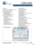
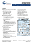
Para ello se seleccionó un micrcontrolador de la compañía Cypress Semiconductor
cuyas principales características eran la posibilidad de realizar conexiones USB y la
posibilidad de crear bloques analógicos y digitales programables, de tal manera que la
mayor parte de hardware del dispositivo, filtros, ammplificadores, etc,. se pudiera crear
mediante software.
III
3
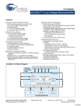
En cuanto al sistema de control mediante USB, gracias a la facilidad del PSoC, no
implica mayor trabajo que el incluir un módulo de USB programable y configurarlo con los
parámetros de transferencia de datos, consumo, etc. que se tengan en función de la
aplicación que se vaya a desarrollar.
Para verificar el buen funcionamiento de todas las partes del equipo, se dividió el
proyecto en bloques funcionales, haciéndolos funcionar por separado en cualquier situación
posible que se pudiera dar, de modo que quedara probado su buen funcionamiento en
cualquier caso posible.
Una vez probado todo por separado se procedió a montar el conjunto y hacer
diferentes pruebas. Sin embargo, no se llego a conectar el dispositivo a la red eléctrica por
falta de materiales para el montaje de un circuito esencial.
Conclusiones
Aunque el proyecto no llegó a probarse en la instalación eléctrica si se comprobó que la
señal correspondiente de X10 era mandada por el microcontrolador PSoC cuando se daba la
orden desde el PC por medio del sistema de control diseñado, por lo que a falta de su
comprobación en la red, se puede decir que se han cumplido con los objetivos del proyecto:
-
Diseñar un emisor de X10
-
Realizar una conexión USB con un PC
-
Realizar un sistema de control del emisor
IV
4
X10 DOMOTIC DEVICE. INTERFACE USB
Author: Desviat Cruzado, Pablo.
Director: Muñoz Frias, José Daniel. Zamora Macho, Juan Luis.
PROJECT SUMMARY
The humankind evolution has generated a series of events that form part of great
transcendence historic stages. Technology is born along human beings and has turned to be
a priority element for social groups that use it, it allows them to live in harmful
environments and survive.
Due to the technological advances generated by years of research, humans have
achieved a high quality life level. Humans are not just looking to fulfil basic survival needs,
they are looking for a comfortable life and control of their surroundings as well.
Considering these new needs, the information technology comes into scene. By
using it, the environment in which a person interacts can be known, can be manipulated and
can be programmed; this environment could be an office or a home itself.
That is how domotics appears. In France, where people love to adapt self-invented
names to new disciplines, the word "domotique" was coined, from the contraction of the
words "domo" and "informatique". This term can be defined as follows: "a home concept
which
unites
all automatisms
related to security
issues, energy
management,
communications, etc.". The objective is to guarantee the home owner an improvement in
comfort, security, energy savings and communication simplicities.
This work reports the project of one student of second grade at Superior School of
Engineering ICAI. It introduces the use of microcontroller and computer technologies to
manipulate the diverse variables that can be found in a home, however it focuses on
illumination control.
The system used to communicate between devices and control all these variables, is
the X-10 protocol.
The X10 standard sends and codificates the information by means of trains of 120
KHz pulses through the mains when this it happens through zero. A code is assigned to each
element of the house in such way that the central element of the system can communicate
directly with the rest of devices and to give them orders by means of other codes. In
summary, it is had defined the different functions that will have to make the device that is
going to be designed:
V
5
After a study of the different existing modules in the market, it was verified that the
great majority was only unidirectional, it means, or they send information or they receive
information, but not both things, that is the reason why another objective was added. The
device must be bidirectional.
As well, at the present time we can find a computer in practically each house,
thought about using this characteristic like an advantage that could make t he use of our
designed device even more comfortable for the user. Other idea was added, to make a
control by a USB connection to a personal computer.
Hardware where the project was realised was chosen as a result of another
objectives. An idea that was had from the first moment was to make the device smaller than
the other existing modules. To achieve this,a microcontrollerr of Cypress company was
selected whose main characteristics were the possibility of realising connections USB and
the possibility of creating programmable analogical and digital blocks, in such a way that
most of hardware of the device, filters, amplifiers, etc. would be possible to be created by
means of software.
VI
6
In order to verify the good operation of all the parts of t he equipment, the project
was divided in functional blocks, making them work separately in any possible situation
that it was possible to be given.
Once checked everything separately it was mounted together and test. However, th device
was never conected to main because there were not materials for the assembly of an
essential circuit.
Conclusions
Although the project was never conected to the electrical system, it were verified that the
corresponding signal of X10 was sent by the microcontroller PSoC when the order occurred
from the PC by means of the designed control system, reason why it is possible to be said
that they have been fulfilled the objectives of the project:
To design an emitter of X10
To realise a connection USB with a PC
To realise a control system of the emitter
MEMORIA
Índice General
Parte I
Capítulo 1
Memoria ............................................................................................. 7
Introducción .................................................................................. 8
1
Motivación del proyecto............................................................................. 8
2
Objetivos del proyecto ............................................................................. 10
3
Metodología .............................................................................................. 11
4
Recursos .................................................................................................... 12
Capítulo 2
Estado del arte ............................................................................ 13
1
Antecedentes ............................................................................................. 13
2
Historia y panorama actual del sistema eléctrico español...................... 15
3
Historia del protocolo X-10 ...................................................................... 37
4
Programmable System on Chip ............................................................... 40
5
Estudio de las tecnologías existentes en España..................................... 45
Capítulo 3
Estructura y organización del proyecto .................................. 60
Capítulo 4
La domótica ................................................................................. 62
1
Introducción.............................................................................................. 62
2
Características de la domótica .................................................................. 64
3
Gestión de la domótica ............................................................................. 65
4
Descripción del sistema domótico........................................................... 67
5
Protocolo de comunicaciones ................................................................... 74
Capítulo 5
El protocolo X-10 ........................................................................ 75
1
Estudio teórico .......................................................................................... 75
2
Razones de la elección.............................................................................. 80
Capítulo 6
PSoC.............................................................................................. 82
1
Capítulo 7
Automatización con el PSoC .................................................... 85
1
Detector de cruce por cero ........................................................................ 87
2
Generador de la señal de 120 KHz........................................................... 91
3
Fuente de 5 V sin transformador ............................................................. 93
4
Módulos PsoC........................................................................................... 96
Capítulo 8
Conexión con el PC mediante USB ........................................ 106
1
Conceptos Generales .............................................................................. 106
2
Proyecto................................................................................................... 111
Capítulo 9
Resultados/Experimentos ........................................................ 117
Capítulo 10
Conclusiones.......................................................................... 124
Capítulo 11
Futuros desarrollos............................................................... 125
Bibliografía........................................................................................................ 126
Parte II
Estudio económico........................................................................ 127
Parte III
Manual de usuario ........................................................................ 130
1
Conexión a PC......................................................................................... 131
2
Uso del programa.................................................................................... 133
3
Desconexión............................................................................................ 139
Parte IV
Código fuente................................................................................. 140
Parte V
Datasheets ..................................................................................... 148
2
Indice de figuras
Figura 2.1. Presa de Aldeadávila ...................................................................... 17
Figura 2.2. Central hidroeléctrica de Puente Bibey........................................ 20
Figura 2.3. Central nuclear de Almaraz........................................................... 24
Figura 2.4. Central térmica de Santurce........................................................... 33
Figura 2.5. Logotipo X10.................................................................................... 37
Figura 2.6. PSoC Designer ................................................................................. 40
Figura 2.7. Ejemplo proyecto PSoC .................................................................. 43
Figura 2.8. PSoC Express ................................................................................... 43
Figura 2.9. Esquema PLC................................................................................... 48
Figura 2.10. Esquema X10.................................................................................. 55
Figura 2.11. Módulo X10.................................................................................... 57
Figura 4.1. Arquitectura domótica ................................................................... 63
Figura 4.2. Gestión domótica............................................................................. 66
Figura 5.1. X10 y señal senoidal ........................................................................ 75
Figura 5.2. Trama de X10 ................................................................................... 79
Figura 6.1. CY8C24894 ....................................................................................... 82
Figura 6.2. Componentes CY8C24894.............................................................. 82
Figura 6.3. Tarjeta PsoCEvalUSB ...................................................................... 84
Figura 7.1. Funciones X10 .................................................................................. 85
Figura 7.2. Esquema detector de cero .............................................................. 87
Figura 7.3. Simulación detector de cero........................................................... 88
Figura 7.4. Ampliación simulación detector de cero ..................................... 88
Figura 7.5. Detector de cero montado .............................................................. 89
Figura 7.6. Detector de cero osciloscopio ........................................................ 89
Figura 7.7. Señal 120 KHz .................................................................................. 91
Figura 7.8. Circuito emisor X10......................................................................... 92
Figura 7.9. Esquema fuente 5V sin transformador ........................................ 93
Figura 7.10. Bloques en PSoC ............................................................................ 96
Figura 7.11. Recursos generales ........................................................................ 97
Figura 7.12. Módulo PWM8 .............................................................................. 99
Figura 7.13. Configuración PWM8 ................................................................... 99
Figura 7.14. Señal 120 KHz .............................................................................. 100
Figura 7.15. Módulo Timer8 ............................................................................ 102
Figura 7.16. Configuración Timer8................................................................. 102
Figura 7.17. Configuración LCD ..................................................................... 104
Figura 7.18. Configuración LEDs.................................................................... 104
Figura 7.19. Configuración pines PSoC ......................................................... 105
Figura 7.20. Salida de la señal de PWM y a los LEDs.................................. 105
Figura 8.1. Paquetes de datos manejados por el CY8C24894 ..................... 107
Figura 8.2. Vista de software de una conexión USB .................................... 108
Figura 8.3. Hardware setup ............................................................................. 111
Figura 8.4. Conexión LEDs .............................................................................. 111
Figura 8.5. Diagramas de flujo del dispositivo y del host........................... 112
Figura 8.6. USB Wizard .................................................................................... 114
Figura 9.1. Programa diseñado de monitorización de luces ...................... 117
Figura 9.2. Comprobación conexión USB ...................................................... 118
Figura 9.3. Encendido de la habitación 1....................................................... 119
Figura 9.4. Señal mandada ON habitación 1................................................. 120
Figura 9.5. Código de dispositivo habitación 1 ............................................ 120
Figura 9.6. Pasos por cero (10 ms) .................................................................. 121
Figura 9.7. Código de encendido .................................................................... 121
Figura 9.8. Señal mandada OFF habitación 1 ............................................... 122
Figura 9.9. Código de dispositivo habitación 1 ............................................ 122
Figura 9.10. Pasos por cero (10ms) ................................................................. 123
Figura 9.11. Código de apagado ..................................................................... 123
Figura 0.1. Esperando conexión...................................................................... 131
Figura 0.2. Conexión tarjeta USB .................................................................... 131
Figura 0.3. Conexión establecida .................................................................... 132
Figura 0.4. Estado LCD todo apagado ........................................................... 132
Figura 0.5. Habitación 1 ................................................................................... 133
Figura 0.6. Habitación 2 ................................................................................... 134
Figura 0.7. Habitación 3 ................................................................................... 135
Figura 0.8. Habitación 4 ................................................................................... 136
Figura 0.9. Varias habitaciones ....................................................................... 137
Figura 0.10. Habitaciones apagadas ............................................................... 138
Figura 0.11. Salida del programa.................................................................... 139
Índice de tablas
Tabla 5.1. Códigos de Casa................................................................................ 76
Tabla 5.2. Códigos de llave ................................................................................ 77
Pablo Desviat Cruzado
Parte I MEMORIA
7
Pablo Desviat Cruzado
Capítulo 1 INTRODUCCIÓN
1 Motivación del proyecto
Este proyecto surge a partir de la idea de automatizar una vivienda
sin necesidad de hacer uso de más cables que los que ya están siendo
utilizados en la instalación eléctrica de la casa. Con esta premisa se eligió
el estándar X10 para llevar a cabo esta idea.
La principal ventaja por la que se ha elegido este estándar para el
desarrollo del proyecto es porque este protocolo está especialmente
orientado hacia la utilización de la red eléctrica de las viviendas utilizando
corrientes portadoras para controlar cualquier dispositivo a través de la
línea de corriente domestica.
Con este protocolo se maneja un direccionamiento sencillo que se
puede utilizar en la red para identificar cualquier elemento, característica
que vendrá muy bien si lo que se pretende es poder automatizar
diferentes dispositivos dentro de la vivienda.
Otras de las diferentes características del X10 y que reflejan el por
qué se eligió este protocolo son:
Es estándar debido a las características de la corriente eléctrica
domestica (220 V y 50 Hz).
Es flexible y fácil de usar gracias a como está constituida la red en el
hogar.
8
Pablo Desviat Cruzado
No hay que configurar nada para que entre en funcionamiento
(Plug an Play).
Da como resultado confort y diversión.
Es una tecnología que aprovecha la red eléctrica que ya está
instalada en la vivienda.
Modularidad y capacidad de crecimiento, con componentes fáciles
de instalar y que no requieren cableados especiales.
Capacidad de interfuncionamiento entre productos.
Para finalizar con esta presentación recalcar que la motivación
principal del proyectista ha sido la de diseñar y construir un dispositivo
que fuera sencillo al uso y que pudiera adaptarse a cualquier hogar actual.
A su vez, y aprovechado que hoy por hoy podemos encontrar un
ordenador en prácticamente cada casa, se pensó en utilizar esta
característica como una ventaja que pudiera hacer aun más cómoda la
utilización del sistema por parte del usuario y por tanto se añadió la idea
de hacer un control por medio de una conexión USB a un ordenador
personal.
Tras el estudio de otros diseños del mismo nivel de dificultad, se
observó la carencia de una bidireccionalidad. Esto hizo que surgiera una
motivación adicional consistente en dotar al proyecto de la capacidad de
poder enviar y recibir información para de ese modo poder comprobar los
estados de los diferentes dispositivos a controlar dentro de la vivienda.
9
Pablo Desviat Cruzado
2 Objetivos del proyecto
Los objetivos se han seleccionado a partir de la metodología que se
usará para desarrollar el proyecto. Esta metodología se basara
principalmente en la descomposición del proyecto en módulos más
sencillos, por lo que automáticamente estos pasarán a ser nuestros
objetivos:
Alimentación del dispositivo
Codificación y decodificación de señales X10
Emisión y recepción de señales X10
Conexión USB
Interfaz gráfica para PC
Ensamblaje de los distintos módulos
Por otro lado tenemos:
Aplicar la tecnología X-10 para controlar el sistema de iluminación
de un hogar
Entender el funcionamiento del protocolo X-10
Intercomunicar elementos a controlar mediante el cableado de
energía eléctrica de un hogar
Desarrollar un sistema central que esté a cargo de la gestión de
todos los elementos de control del hogar mediante el uso de una
tarjeta de desarrollo PsOC que incluya una conexión USB con un
ordenador personal.
10
Pablo Desviat Cruzado
3 Metodología
Como ya se ha comentado en el apartado anterior, se seguirá una
metodología de bloques o módulos que serán diseñados y probados por
separado de manera que la consecución del proyecto sea más sencilla y los
problemas que surjan durante el transcurso de este sean más fácilmente
solucionables.
Para el módulo de alimentación, de codificación y decodificación de
señales X10 y emisión y recepción de señales X10 se usarán programas
tipo CAD para su diseño y prueba. Una vez que estos funcionen
correctamente se llevaran a una tarjeta de desarrollo llamada PSoC cuyas
características se comentarán posteriormente.
En cuanto a la conexión por USB con el ordenador se seguirá un
procedimiento similar a los anteriores módulos. Más tarde se pensará y
programará un driver que haga posible la conexión entre el dispositivo a
construir y el ordenador.
Por último se programará en visual basic o algún lenguaje de
programación similar un entorno gráfico que permita al usuario
interactuar con el dispositivo de una forma sencilla e intuitiva.
Una vez creados todos estos módulos se procederá al ensamblaje de
todos ellos para formar el dispositivo final.
11
Pablo Desviat Cruzado
4 Recursos
Entre los recursos que se utilizarán en este proyecto el principal de
ellos es una tarjeta PSoC (Programmable System-on-Chip) de la compañía
Cypress. En concreto se usará la tarjeta PSoCEvalUSB ya que entre muchas
de sus características se encuentra la posibilidad de conectarse mediante
USB. También dispone de un modulo LCD, potenciómetros, LEDs e
incluso una protoboard en el caso de que fuera necesaria.
La
principal
ventaja de esta placa es que nos va a permitir introducir todos los circuitos
analógicos de nuestro diseño en un microchip por lo que el número de
componentes a utilizar se reducirá y por tanto el tamaño del dispositivo
final.
La programación de dicho microchip, así como los diseños de los
circuitos que luego se introducirán en él, se van a realizar con un software
de la misma compañía, el cual, puede bajarse libremente de su página
web.
Para las pruebas de los circuitos se utilizará un programa tipo CAD
como el PSpice de la compañía Cadence
12
Pablo Desviat Cruzado
Capítulo 2 ESTADO DEL ARTE
1 Antecedentes
“La creciente dedicación del Homo Erectus a la caza, dio origen al
desarrollo de una organización social claramente humana, basada
en una estricta división del trabajo entre hombres, cazadores y
mujeres que buscaban y recogían el alime nto ... desarrollando un
lenguaje que muestra al hombre como el único animal cultural, que
pudo sobrevivir y triunfar adaptando su comportamiento, más que
su cuerpo, a las modific aciones del medio.”
- Jonathan N. Leonard -
Una vivienda domótica se puede definir como: "aquella vivienda en
la que existen agrupaciones automatizadas de equipos, normalmente
asociados por funciones, que disponen de la capacidad de comunicarse
interactivamente entre sí de un bus doméstico multimedia que las
integra".
Para lograr la intercomunicación de estos equipos se cuenta con la
transmisión de información por la línea de alimentación eléctrica. Esa
información se envía siguiendo las normas del protocolo X-10, que será
explicado posteriormente. Este intercambio se logra mediante circuitería
eléctrónica de potencia y microcontroladores PsoC, encargados de
decodificar y/o codificar la información a transmitir.
En este apartado se tratarán, a modo de situar al lector dentro del
ámbito donde se ubica este proyecto, la energía eléctrica en España, el
13
Pablo Desviat Cruzado
desarrollo del protocolo X-10 y el desarrollo de los microcontroladores
PsOC de Cypress.
Posteriormente se procederá a comentar el estado actual de las
tecnologías basadas en el envío de información a través de la red eléctrica.
14
Pablo Desviat Cruzado
2 Historia y panorama actual del sistema eléctrico español
El siglo XIX
La primera referencia de la aplicación práctica de la electricidad en
España data del año 1852 en el que el farmacéutico Domenech, en
Barcelona, fue capaz de iluminar su botica empleando un “método de su
invención”. En Madrid, ese mismo año, se hicieron pruebas de
iluminación empleando una “pila galvánica” en la plaza de la Armería y
en el Congreso de los Diputados. Ya en 1873 se importó una pequeña
dinamo para la Escuela de Ingenieros Industriales de Barcelona y en 1875
se importó una segunda máquina que instalada en la fragata Victoria,
anclada a tres kilómetros de Barcelona y accionada por medio de la
máquina de vapor de la fragata, logró iluminar las Ramblas, la Boquería,
el Castillo de Montjuic y parte de los altos de Gracia.
A partir del año siguiente comienza la electrificación industrial en
España, siendo La Maquinista Terrestre y Marítima la primera empresa
que suscribió un contrato de suministro eléctrico y posteriormente Tejidos
Tolrá en Castellar, Hilados Ricart en Manresa, el Canal Imperial de
Aragón... Todos estos encargos dieron pie a la constitución de la Sociedad
Española de Electricidad por José Dalmau e hijo, sociedad que figura en
los anales como primera empresa eléctrica española.
En 1878 se ilumina por primera vez la Puerta del Sol en Madrid, a
continuación el Palacio de Bellavista, sede del Ministerio de la Guerra y
los Jardines del Buen Retiro. En 1883 la Plaza de la Constitución en
Valencia y el Puerto del Abra en Bilbao. El desarrollo de las aplicaciones
eléctricas cobró tal impulso que en 1885 ya se publicó un primer decreto
que ordenaba las instalaciones eléctricas y tres años más tarde una Real
15
Pablo Desviat Cruzado
Orden regula el alumbrado eléctrico de los teatros, prohibiendo
expresamente el alumbrado con gas y autorizando las lámparas de aceite
sólo como sistema de emergencia.
Este acelerado desarrollo de la industria
eléctrica dio pie a la
creación de nuevas empresas en las últimas
dos décadas del siglo XIX, algunas de las cuales después de múltiples
compras y fusiones existen todavía
en la actualidad.
No obstante, el desarrollo eléctrico tropezaba en el siglo XIX con
una importante dificultad: la electricidad era generada en forma de
corriente continua y no era posible su transporte a larga distancia. En
consecuencia, el emplazamiento de las centrales construidas en el siglo
XIX estuvo fuertemente condicionado por la proximidad de un centro de
consumo. Este hecho, que no tenía excesiva importancia en el caso de los
grupos térmicos, resultaba trascendente para el aprovechamiento de los
recursos hidráulicos, ya que sólo podían ser aprovechados aquellos
recursos que se encontraban próximos a centros de consumo, aunque
también se dio la circunstancia de que el emplazamiento de los recursos
hidráulicos determinó, en algunas ocasiones, la localización de algunas
industrias.
16
Pablo Desviat Cruzado
Las tres primeras décadas del siglo XX
En 1901 se publicó la primera estadística oficial según la cual
existían en España 859 centrales eléctricas que sumaban 127.940 HP, el
61% de esta potencia mera de origen térmico mientras que el 39% restante
utilizaba la energía hidráulica como fuerza motriz. Con la aparición de la
corriente alterna, a principios del siglo XX, cambió el panorama. Se abrió,
gracias a ella, la posibilidad de transportar electricidad a gran distancia y,
por tanto, de llevar a cabo un desarrollo a gran escala de las centrales
hidroeléctricas.
Figura 2.1. Presa de Aldeadávila
La construcción de las obras hidroeléctricas de un cierto tamaño en
las primeras décadas del siglo XX exigía una utilización de recursos
económicos inhabitual hasta entonces, por su magnitud, dentro de un
sector eléctrico incipiente. Para hacer frente a este reto económico y
financiero, se crearon numerosas sociedades anónimas dedicadas a la
producción y distribución de electricidad, algunas de las cuales existen
todavía hoy. Antes del proceso de concentración que ha vivido el sector
17
Pablo Desviat Cruzado
eléctrico español en la última década era muy frecuente en las empresas
eléctricas la aparición del término "hidroeléctrica" o "salto" en su
denominación social, prueba concluyente del origen de la Sociedad (por
ejemplo, Hidroeléctrica Española, Hidroeléctrica Ibérica, Saltos del Duero,
Saltos del Sil, Hidroeléctrica de Cataluña, Hidroeléctrica del Cantábrico,
Saltos del Nansa, Fuerzas Hidroeléctricas del Segre).
En la década de los años veinte, la política hidráulica española
comenzó a plantearse como objetivo el aprovechamiento integral de las
cuencas hidrográficas. La Confederación Sindical del Ebro fue la primera.
Este planteamiento llevó, en la década siguiente, al inicio del
aprovechamiento integral de la cuenca del Duero, operación que estaba ya
diseñada perfectamente en los años cuarenta y sirvió de modelo a seguir
para el desarrollo del resto de las cuencas peninsulares.
Esta política hidráulica estuvo basada en el ordenamiento jurídico
existente, el cual tenía como principal elemento la Ley de Aguas de 13 de
junio de 1879, que ha sido considerada como texto modélico,
manteniéndose en vigor durante más de un siglo, hasta el año 1985 en que
fue sustituida por la nueva Ley de Aguas.
A finales de los años veinte, la estructura de la generación eléctrica
en España había cambiado radicalmente en comparación con la de
principios de siglo: se había multiplicado la potencia instalada por 12
hasta alcanzar 1.154 MW y el 81% de la producción era de origen
hidroeléctrico en 1929.
En los años siguientes hasta 1936 se produjo un aumento moderado
del consumo eléctrico, si se tiene en cuenta el bajo grado de electrificación
existente: el 5% anual, de tal forma que a principios de dicho año la
potencia instalada ascendía a 1.491 Mw y existía un cierto exceso de
capacidad de producción.
18
Pablo Desviat Cruzado
La Guerra Civil y la posguerra
Durante los años en que se produjo la Guerra Civil y los primeros
años de la posguerra se produjo un estancamiento de la capacidad de
producción, ya que, aunque entraron en servicio algunas instalaciones,
otras fueron destruidas o seriamente dañadas. La sequía de 1944- 45
impidió atender una demanda creciente, con lo que el exceso de capacidad
de producción de la década anterior se convirtió en un importante déficit.
En los años de la posguerra, de austeridad y escasez, a los
problemas internos vinieron a sumarse los derivados de la Segunda
Guerra Mundial y el bloqueo internacional, que impedía la importación de
bienes de equipo, así como la autarquía.
En suma, en los años cuarenta el desarrollo del sistema eléctrico
tropezó con grandes dificultades. Al estar sometida la venta de
electricidad a unos precios estables en un contexto de elevada inflación,
las empresas se vieron en serias dificultades económicas, lo que provocó
un desfase entre el ritmo de construcción de nuevas instalaciones de
generación y el crecimiento de la demanda, por lo que el déficit del año
1944 se convirtió en crónico hasta el final de la década. A este déficit
también contribuyeron los impresionantes crecimientos de la demanda, de
hasta el 27% anual. La constitución de una serie de empresas eléctricas de
carácter público en los años cuarenta (Empresa Nacional de Electricidad,
Endesa, en 1944, Empresa Nacional Hidroeléctrica del Ribagorzana,
ENHER, en 1949…) vino a sumarse al esfuerzo que hasta entonces había
sido realizado en exclusiva por empresas eléctricas privadas, lo cual dio
un fuerte impulso al desarrollo eléctrico, que continuó su marcha a buen
ritmo en los años siguientes.
19
Pablo Desviat Cruzado
En este contexto fue el propio sector el que puso de manifiesto la
necesidad de llevar a cabo una explotación más eficiente, coordinada y
racional de los medios de producción y de las redes de transporte a nivel
nacional.
Figura 2.2. Central hidroeléctrica de Puente B ibey
Esta iniciativa se plasmó en la práctica con la creación en 1944 de la
empresa Unidad Eléctrica S.A. (UNESA), integrada entonces por las 17
principales compañías del sector. A UNESA se encomendó en aquel
momento la promoción de las interconexiones de los distintos sistemas
eléctricos regionales y de éstos con las centrales eléctricas que fueran
necesarias para completar la red primaria o de transporte y la creación del
“Dispatching Central”, desde donde se dirigía la explotación conjunta del
Sistema Eléctrico Nacional, decidiendo qué centrales tenían que funcionar
en cada momento y qué intercambios de electricidad entre zonas eran
necesarios para asegurar el abastecimiento al conjunto del país. Esta
oficina posteriormente, en 1953, se pasó a denominar RECA (Repartidor
Central de Cargas).
20
Pablo Desviat Cruzado
La década de los 50
La aplicación a partir del primero de enero de 1953 de las Tarifas
Tope Unificadas permitió liberar al sector eléctrico del pesimismo con que
se venía desenvolviendo en la época anterior e incentivó el ritmo de
construcción de nuevas centrales, lo que trajo consigo una progresiva y
rápida disminución del déficit de capacidad de producción, esto es, de las
restricciones eléctricas que llegaron a desaparecer completamente en el
año 1958. Este nuevo tratamiento de las necesidades del sector eléctrico
contribuyó al despegue de los años cincuenta y a la superación de las
causas que impedían el desarrollo industrial, acelerando la normalización
interna una vez superada la etapa de la reconstrucción.
21
Pablo Desviat Cruzado
La década de los 60
El Plan de estabilización de 1959, la aparición del turismo, la
apertura al exterior, etc., fueron hechos que dieron pie desde los primeros
años sesenta a una fase de consolidación y crecimiento rápido de la
economía española a ritmos muy elevados, que conllevaron importantes
crecimientos relativos de la demanda eléctrica. En estos años se puso
claramente de manifiesto la ventaja que suponía contar con una red
interconectada para atender instantáneamente a una demanda creciente a
un elevado ritmo, lo que permitió aumentar sustancialmente la garantía
de suministro a los clientes y aprovechar al máximo la potencia total
disponible y, a su vez, disminuir las importantísimas inversiones
necesarias logrando un abaratamiento de las tarifas. A esto también
contribuyó la reducción de costes por economía de escala que supuso el
aumento de tamaño unitario de los grupos generadores.
Durante esta década se produjo un aumento muy importante de la
potencia instalada, que pasó de 6.567 MW a finales de 1960 a 17.924 a
finales de 1970. La producción eléctrica se triplicó, alcanzándose los 56.500
GWh en ese año, 1970. La estructura de generación se modificó
sustancialmente: la producción hidroeléctrica pasó de suponer un 84% de
la producción en 1960 a un 50% en 1970, a pesar de que durante esa
década se produjo un gran desarrollo del equipo hidroeléctrico. También
se incrementó sustancialmente el equipo y la producción con fuel-oil en un
contexto de bajos precios del petróleo.
En el año 1968 se incorporó la primera central nuclear: la Central
José Cabrera, en Zorita de los Canes (Guadalajara). Otros hechos
significativos para el sector eléctrico en esa década fueron la aparición de
un pri mer ensayo planificador en el ámbito de la energía con motivo del
Plan de Desarrollo de 1964 y el primer Plan Eléctrico Nacional, de 1969
22
Pablo Desviat Cruzado
que programaba las instalaciones de generación a acometer en los
próximos años. Durante esta década se intensificaron las acciones
encaminadas a la electrificación rural, consiguiéndose prácticamente la
universalización del servicio eléctrico en España.
23
Pablo Desviat Cruzado
La década de los 70
Comenzaba esta década con una aparente continuidad respecto a la
etapa anterior hasta que en mayo de 1973 se empezó a producir una
escalada de los precios del petróleo, que se multiplicaron casi por seis en
menos de un año. Una parte sustancial del parque térmico puesto en
servicio en los años anteriores utilizaba derivados del petróleo como
combustible, debido a la estabilidad en precios y su facilidad de
utilización hasta esos momentos. Dados los largos períodos de
construcción de las centrales, la mayor parte de los grupos de generaci ón
que entraron en servicio en el período 1973- 76 eran grupos de fuel-oil, ya
que respondían a proyectos contratados con anterioridad a la primera
crisis. Ante ésta, la sociedad española no reaccionó con agilidad, el plan
energético en elaboración no fue aprobado hasta 1975 y fue revisado en
1977. La segunda crisis del petróleo en 1979 dio lugar a otro Plan
Energético (PEN-83) en el que ya se tomaron serias medidas para contener
la dependencia del petróleo aunque sus frutos no se vieron hasta bien
entrada la siguiente década.
Figura 2.3. Central nuclear de Almaraz
24
Pablo Desviat Cruzado
La década de los 80
En el ámbito de la generación eléctrica y en línea con las propuestas
de la Agencia Internacional de la Energía, estos años se caracterizaron por
el desarrollo de tecnologías que permitieran reducir la dependencia del
petróleo. En 1980 se promulgó la Ley de Conservación de la Energía,
todavía vigente, que perseguía un triple fin: reducir la dependencia del
petróleo, fomentar el ahorro de energía y promover las fuentes de energía
renovables.
En línea con esas directrices, en la primera mitad de la década
entraron en servicio las centrales de carbón nacional de 350 MW, que
formaban parte del denominado Plan Acelerado de Centrales Térmicas de
Carbón y diversos grupos situados en la costa para utilizar carbón
importado.
Simultáneamente fue desarrollándose gran parte del programa
nuclear. Entre 1980 y 1986 entraron en servicio cinco grupos nucleares con
una potencia inicial de más de 4.500 MW y casi se finalizo el
aprovechamiento del potencial hidroeléctrico técnico y económicamente
viable con la incorporación durante la década de algo más de 3.000 MW
hidroeléctricos, en gran parte en instalaciones de bombeo puro o mixto
ligadas en cierta medida al equipo nuclear, dado que tenían como objetivo
flexibilizar la generación en base a esos grupos.
Esa década se caracterizó por las importantes inversiones que hubo
de acometer el Sector Eléctrico (más de 3,5 billones de pesetas en el
período
1980-86) en un entorno
de crisis económica altamente
desfavorable: elevada inflación, altos tipos de interés real y bajo
crecimiento de la demanda. Además, y dado lo reducido del mercado de
capitales nacional el sector tuvo que acudir a los mercados internacionales
25
Pablo Desviat Cruzado
en busca de financiación, básicamente en dólares americanos, divisa que
experimentó una elevada apreciación durante esos años.
En definitiva, a finales de los ochenta el sector eléctrico español se
encontraba en una situación difícil: por una parte existía una elevada
capacidad ociosa, como consecuencia de la política de diversificación, que
fomentó la construcción de centrales de combustibles alternativos al
petróleo, y conllevó una reducción de la utilización de las centrales de
fuel, que únicamente jugaban un papel de reserva, con crecimientos
moderados de la demanda que dieron lugar a una situación de sobre
equipamiento y, por otra parte, un elevado endeudamiento con altos tipos
de interés real. Las empresas veían perpetuarse la histórica insuficiencia
tarifaria, consecuencia del papel que se suele asignar a los precios
eléctricos para contener la inflación.
Los primeros pasos para estabilizar la situación económicofinanciera de las empresas del sector se dieron en 1985, en el que se
produjo un intercambio de activos (de unos 7.000 MW) que permitió
aliviar la situación de aquellas empresas más activas en la política de
sustitución del petróleo. Pero, sin duda, el mayor logro en la senda de la
estabilización del sector fue el establecimiento de un nuevo sistema de
cálculo de las tarifas eléctricas, que permitiera disminuir el desequilibrio
financiero. Este sistema, conocido como Marco Legal y Estable, se empezó
a aplicar paulatinamente a partir de 1988 y tenía como parámetros
fundamentales una metodología de amortización y retribución de las
inversiones, una retribución de los costes de producción y distribución en
base a valores estándar, un sistema de compensaciones entre los agentes y
una corrección por desviaciones al finalizar el año.
26
Pablo Desviat Cruzado
La década de los 90
Durante los años noventa, de vigencia del Marco Legal y Estable, la
situación económico-financiera de las empresas mejoró sustancialmente, a
lo que también ayudó la existencia de una sobrecapacidad, que hacía
innecesario acometer nuevas inversiones en generación, como se ponía de
manifiesto en el Plan Energético Nacional de 1990, y la estabilidad
económica que proporcionó la integración real en la UE. Esa estabilidad
permitió a las empresas del sector generar fondos para sanear su
estructura financiera y acometer su expansión en otros sectores
económicos y en otros países, fruto de la cual en algunos casos las
empresas eléctricas españolas se han convertido en importantes
multinacionales que ocupan destacados puestos en el sector de las
“utilities”. Previamente a esa expansión internacional se había producido
en el sector eléctrico español un proceso de concentración de empresas
que dio lugar a la actual ENDESA (a partir de la fusión del Grupo Endesa
del INI con Cía Sevillana de Electricidad, Fecsa, H. Cataluña y Eléctricas
Reunidas de Zaragoza) y a IBERDROLA (resultado de la fusión de H.
Española e Iberduero).
Por último, señalar que al hilo de los aires de liberalizadores que
empezaban a correr por Europa, en 1995 fue promulgada la Ley de
Ordenación del Sistema Eléctrico Nacional (LOSEN) que ya preveía la
creación de un Sistema de Generación Independiente, que funcionaría en
régimen de competencia, manteniendo un régimen regulado en el que, en
principio, se inscribirían las instalaciones de generación ya existentes. Esta
ley no llegó a desarrollarse.
27
Pablo Desviat Cruzado
El nuevo marco eléctrico
En 1996 el Consejo de la Unión Europea aprobó la Directiva sobre
Normas Comunes para el Mercado Interior de la Electricidad, que
contiene unos objetivos claros y unos criterios mínimos de liberalización e
introducción de la competencia en el sistema eléctrico. La mayoría de los
países comunitarios deberían adaptar sus legislaciones eléctricas al nuevo
esquema con anterioridad al 19 de febrero de 1999, aunque se han
producido algunos retrasos. Este cambio en los planteamientos no fue un
hecho aislado en la burbuja de la UE. Desde hacía ya varios años, diversos
países desarrollados en distintas partes del mundo habían puesto en
marcha procesos de reestructuración de sus respectivos sistemas eléctricos
con criterios de liberalización e introducción de la competencia.
España fue uno de los primeros países en la adopción de los
criterios emanados de esta Directiva. Como consecuencia de las
conversaciones y acuerdos entre el sector eléctrico y la administración
energética que tuvieron lugar durante 1996 y 1997, y que se plasmaron en
el Protocolo Eléctrico, el 1 de enero de 1998 entró en vigor la Ley 54/1997
del Sector Eléctrico, que introdujo los cambios normativos más
importantes dela historia del sector en España. Esta ley, a la que luego nos
referiremos, supuso mucho más que una transformación del sistema
eléctrico que existía hasta entonces, ya que incorporó nuevas reglas en
todas las actividades necesarias para llevar el producto hasta el cliente,
esto es, nuevas reglas para las actividades de producción, transporte,
distribución y comercialización de la electricidad.
Por otra parte, además de los cambios que está sufriendo en los
países de la UE el sistema eléctrico, no hay que olvidar las posibles
consecuencias sobre este sector debidas a acuerdos a nivel internacional o
mundial en otras materias como, por ejemplo, el medio ambiente. La
28
Pablo Desviat Cruzado
contención de las emisiones de gases de efecto invernadero que figura en
el Protocolo de Kioto y las diversas directivas medioambientales de la UE
(grandes instalaciones de combustión, techos nacionales de emisión,...)
pueden introducir a medio plazo importantes cambios en la estructura de
la generación eléctrica. Tampoco se deben olvidar los cambios que puede
introducir el desarrollo tecnológico en la estructura de la generación. La
reciente aparición de las tecnologías de generación mediante ciclos
combinados de gas que utilizan como combustible un recurso abundante y
limpio, con un elevado rendimiento y con bajos costes de inversión, o la
introducción a
nivel
comercial
de
determinadas
tecnologías
de
aprovechamiento de energías renovables, son avances que están
influyendo de forma decisiva en la modificación de la estructura de
generación eléctrica.
La estructura empresarial de las empresas eléctricas se ha adaptado
rápidamente a los requerimientos del nuevo marco regulatorio. Las
principales características del nuevo marco son las siguientes:
Distingue entre actividades reguladas, tales como el transporte, la
distribución, la gestión económica y la gestión técnica del sistema, y
las actividades que se realizan en régimen de competencia: la
generación, la comercialización y los intercambios internacionales.
Para ello se estableció la separación, incluso jurídica, entre las
actividades reguladas y no reguladas, y entre las actividades
reguladas la necesidad de la separación contable.
La
liberalización
de
las
actividades
de
generación
y
comercialización dio pie a la libre creación de nuevas empresas y a
29
Pablo Desviat Cruzado
la implantación de grupos extranjeros, que actúan en estos
segmentos de la actividad eléctrica.
En cuanto al transporte y la distribución, se consideran actividades
con
carácter
de
monopolio
natural
manteniéndose
como
actividades reguladas, cuya liberalización se consigue mediante el
acceso a terceros de la red con pago de unas tarifas de acceso en
función de la potencia, la energía y la tensión de suministro. Por
tratarse de una actividad regulada pero con libre acceso de terceros,
la única planificación, de carácter vinculante, que permanece es la
relativa al sistema de transporte.
Los intercambios de energía con otros países de la UE o con terceros
países están sometidos, en todo caso, a autorización administrativa
del Ministerio de Economía. Las importaciones las pueden llevar a
cabo los productores, los distribuidores, los comercializadores y los
consumidores cualificados. Las exportaciones pueden realizarse
por los productores y comercializadores nacionales. Por su parte, el
Operador del Mercado puede realizar intercambios a corto plazo
con el fin de garantizar la calidad y seguridad del suministro.
En relación con la retribución económica de las actividades
eléctricas, ésta se lleva a cabo con cargo a los ingresos por tarifas y
precios establecidos libremente. Además, se retribuyen los costes
permanentes del sistema, entendiendo por tales los del Operador
del Mercado, los del Operador del Sistema, los derivados de
actividades insulares y extrapeninsulares, los de la Comisión del
Sistema Eléctrico Nacional y los costes de transición a la
30
Pablo Desviat Cruzado
competencia. También prevé la ley que los consumidores se hagan
cargo
de
los
costes
de
diversificación
y
seguridad
de
abastecimiento, que son los siguientes: las primas a la producción
en régimen especial para promover el desarrollo de la generación
mediante cogeneración, residuos y energías renovables, los costes
asociados a la moratoria nuclear, los de financiación del segundo
ciclo de combustible nuclear y los costes del stock estratégico del
combustible nuclear.
Se creó la figura del Operador del Mercado cuya misión es la
gestión económica del mercado. Esta entidad está supervisada por
el Comité de Agentes del Mercado que supervisa la casación y
liquidación, conoce las incidencias que hayan tenido lugar y
propone las reglas de funcionamiento del mercado.
También se creó la figura del Operador del Sistema, responsable de
la gestión técnica del mismo, esto es, de garantizar la continuidad,
la calidad y la seguridad del suministro. Es el encargado de la
coordinación del sistema de producción y del sistema de transporte
y de su planificación.
31
Pablo Desviat Cruzado
La planificación eléctrica Período 2002-11
En los últimos cinco años, la demanda de electricidad se ha
incrementado en más de un 30%, muy por encima de las previsiones. Ello
ha ido acompañado de un incremento aún mayor de la demanda punta
(44%) que es la variable fundamental de cara a determinar las necesidades
de infraestructuras eléctricas, tanto de generación como de transporte y
distribución. En este mismo período los precios medios de la electricidad
se han reducido un 17% en términos corrientes lo que equivale, teniendo
en cuenta la inflación, a una disminución del 30%.
El sector eléctrico en su conjunto se ha visto con importantes
dificultades de atender puntualmente este crecimiento no previsto, debido
a los plazos de desarrollo que requieren todas estas infraestructuras
(varios años en el mejor de los casos), en un entorno, además, de creciente
incertidumbre por la liberalización del sector y de ausencia de un sistema
regulatorio predecible.
Como consecuencia, en el año 2001, desde un punto de vista de
desarrollo de las infraestructuras, el sector eléctrico español se
caracterizaba por los siguientes elementos: equipamiento de generación
instalado muy ajustado (margen de reserva muy reducido), que
incrementa el riesgo de falta de abastecimiento en casos de puntas de
demanda muy acusadas o de indisponibilidades fortuitas superiores a las
normales; una red de transporte que presenta problemas de saturación,
tanto zonales como globales, en períodos de alta demanda y cuyo
desarrollo se ha visto retrasado en muchos casos por falta de
autorizaciones
administrativas;
una
demanda
creciente,
con
una
importante sensibilidad al precio de la electricidad y sin incentivos
encaminados a una mejor gestión de la curva de carga; asimismo, en
materia de gas natural se presenta un déficit de infraestructuras gasistas,
32
Pablo Desviat Cruzado
previsiblemente hasta el 2005, que podría dar lugar a problemas puntuales
de falta de suministro a las centrales de gas en los próximos inviernos.
En estas circunstancias, el desarrollo de una planificación energética
Integral (obligatoria más indicativa) se acogió desde el sector eléctrico
como una iniciativa del Gobierno necesaria para abordar las fuertes
transformaciones, que se están dando y que han de tener lugar en el
futuro.
Figura 2.4. Central térmica de Santurce
El nuevo plan energético para el período 2002-11, realizado durante
el presente año y recientemente aprobado por el Gobierno, conlleva un
cambio considerable en los modos de acometer el proceso planificador en
España. En primer lugar hay que señalar que por primera vez se acomete
una planificación conjunta de las redes de transporte eléctrico y de gas
debido lógicamente a la interacción que se produce al incorporar de forma
masiva ese combustible para generación eléctrica. En segundo lugar hay
que señalar el distinto carácter de la planificación de dichas redes de
transporte respecto a la planificación de los medios de generación
33
Pablo Desviat Cruzado
eléctrica. Mientras la planificación de redes tiene carácter vinculante por
tratarse de actividades reguladas, la de la generación, que es una actividad
liberalizada, es meramente indicativa y tiene por finalidad facilitar la toma
de decisiones de inversión por parte de los agentes.
Por tanto, y como consecuencia de lo anterior, la planificación
realizada contiene tanto las propuestas de desarrollo de la redes de
transporte de gas y electricidad, que se corresponden con la planificación
obligatoria, como un conjunto de datos e informaciones sobre las
previsiones de fluctuación de los vectores que inciden en el sector
energético, con los que definir, con mayor precisión, las redes de
transporte necesarias y las necesidades de nueva generación.
El resultado del proceso planificador es la definición de las redes de
transporte eléctrico así como los gasoductos de la red básica y las
instalaciones de almacenamiento de gas e indicaciones sobre las
necesidades de incorporación de potencia al Sistema, aunque sin fijar un
valor mínimo de dicha incorporación.
Así, se prevé un incremento de las redes de 220 y de 400kV de unos
12.500 Km, lo que supone un incremento de un 40% respecto a la situación
actual. También se prevé un aumento de la capacidad de transformación
de 32.500 MVA (+69%), con lo que la inversión en las redes de transporte
supondrá unos 2.720 millones de euros. Adicionalmente serán necesarias
importantes inversiones en el área de distribución que aunque no son
contempladas por la planificación – que se limita a valorar el coste de las
redes en niveles de transporte- deben ser consideradas, si se desea tener
una visión global del nivel de inversiones preciso en el Sistema Eléctrico.
Estas inversiones en distribución según estimaciones del sector, pueden
alcanzar los 11.700 millones de euros para el período de planificación.
Las inversiones del sistema gasista en este período totalizarán unos
5.300 millones de euros en redes de transporte (1.226 millones de euros),
34
Pablo Desviat Cruzado
plantas regasificadoras (2.661 millones de euros), almacenamientos (941
millones de euros) y estaciones de compresión (341 millones de euros).
Pero el grueso de la inversión se realizará en el ámbito de la
generación eléctrica, dado que se prevé que durante esta década entren en
servicio cerca de 15.000 MW en centrales de ciclo combinado de gas
natural, con una inversión de unos 6.500 millones de euros. En el
horizonte 2011 la producción de estas centrales conjuntamente con las
instalaciones de cogeneración que consumen gas natural supondrá el 34%
de la generación eléctrica en detrimento sobre todo de la producción con
carbón. Adicionalmente, aparte de las inversiones en nueva generación,
hay que tener en cuenta las inversiones recurrentes necesarias para
mantener en óptimas condiciones el equipo existente en la actualidad y
que se estiman en unos 5.800 millones de euros para el período citado.
El otro pilar de la nueva generación serán las energías renovables.
El Documento prevé la incorporación de unos 14.000 MW básicamente en
instalaciones de energía eólica (9.000 MW adicionales) y de biomasa (3.100
MW). De esta forma, se persigue que al final del período de planificación,
las fuentes de energía renovable supongan un 29% de la producción
eléctrica nacional y un 12,3% del consumo de energía primaria en España.
Para ello serán necesarias unas inversiones en estas tecnologías del orden
de los 12.000 millones de euros.
En definitiva, la planificación realizada supone una inversión total
de 26.500 millones de euros, de los cuales el 80% corresponderán al sector
eléctrico y el 20% al sector del gas. Si se tienen en cuenta, además de las
inversiones contempladas en la planificación (transporte y nueva
generación), las inversiones que se necesitan en distribución y las
inversiones recurrentes en el equipo generador ya existente resulta una
inversión global del sector eléctrico en el período 2002-11 de más de 38.000
millones de euros, lo que equivale a invertir en diez años tres veces la
35
Pablo Desviat Cruzado
actual cifra de negocio anual, además de hacer frente al resto de costes del
sistema.
Las cifras anteriores ponen de manifiesto la necesidad de un marco
regulatorio adecuado, que permita establecer los ingresos necesarios con
objetividad y, en definitiva, recuperar y retribuir las inversiones que se
prevén de forma suficientemente razonable.
Desde el punto de vista de la sostenibilidad, la planificación
realizada prevé un desarrollo con criterios sostenibles, basado en las
energías renovables, la producción de calor y electricidad con mayor
eficiencia energética y la utilización de los ciclos combinados de gas
natural que proporcionan elevados rendimientos, todo ello para lograr
una garantía de suministro razonable. Es decir recoge, entendemos que
adecuadamente, la mayor parte de los postulados para avanzar en la
senda del desarrollo sostenible, aunque pudiera echarse en falta un mayor
énfasis en lo relativo a las políticas de ahorro energético en el consumo
final de energía, aspecto que se ha pospuesto para un plan posterior.
36
Pablo Desviat Cruzado
3 Historia del protocolo X-10
Los orígenes de X-10 están en una compañía llamada Pico
Electronics, en Glenrothes, Escocia. Pico fue fundada en 1970 por un grupo
de ingenieros que trabajaban para General Instrument Microelectronics
(G.I.). Los fundadores de Pico tuvieron la idea de que era posible
desarrollar una calculadora chip única; la mayoría de calculadoras en
aquel momento usaban como mínimo 5 circuitos integrados (ICs). Pico lo
hizo y esta calculadora IC fue precisamente el primer microprocesador del
mundo, una historia muy diferente a lo que Intel o Texas Instruments
aseguran.
Figura 2.5. Logotipo X10
Pico pasó a desarrollar una gama de calculadoras ICs que fueron
fabricadas por G.I. y vendidas a fabricantes de calculadoras como
Bowmar, Litton, y Casio. A Pico le pagaron los derechos de patente de ICs
pero como el precio de los ICs para calculadoras descendió de $20 a menos
de un dólar, los directores de Pico vieron la necesidad de desarro llar
productos completos y no sólo Ics.
En 1974 presentaron la idea de un cambiadiscos que seleccionaría
las pistas en un disco LP vinilo. Pico desarrolló el producto entero que
incluía el IC de costumbre, todos los aspectos mecánicos, la caja, etc. Se
necesitó un fabricante, BSR en ese momento era el fabricante más grande
37
Pablo Desviat Cruzado
del mundo de cambiadores de discos. Por lo tanto se formó una nueva
empresa llamada Accutrac Ltd., una asociación a medias entre BSR y Pico.
BSR fabricó el cambiador de discos, llamado Accutrac 2000, y pasó a la
fabricación de varios modelos desarrollados por Pico.
El éxito de los proyectos Accutrac financió el desarrollo de la
siguiente gran idea. El Accutrac tenía muchas características únicas, como
que era teledirigido. Utilizaba un telecomando “ultrasónico” desarrollado
por Pico. Esto pasó a mediados de los 70, incluso antes de que fuera
popular para los televisores con mando a distancia. La idea del mando a
distancia de Accutrac engendró la idea de controlar las luces y los
electrodomésticos con mando a distancia, y así en 1975 el proyecto X-10
fue concebido (había 8 proyectos diferentes de calculadoras IC y Accutrac
era el proyecto X9). Se llegó a la idea de utilizar la instalación eléctrica
existente
AC
para
transmitir
señales
para
controlar
luces
y
electrodomésticos.
Los ICs se desarrollaron en un periodo de tres años, y se realizaron
extensas pruebas en una casa. Después de numerosas pruebas se encontró
que el sistema funcionaba bien durante el día, pero parecía que paraba de
funcionar cuando el dueño venía a verlo por la tarde. Después de una
investigación exhaustiva se descubrió que cuando todos llegaban a casa de
trabajar y empezaban a poner en marcha sus electrodomésticos, el ruido
en la línea AC aumentaba hasta tal punto que el sistema paraba de
funcionar. Para remediarlo, los ingenieros de Pico propusieron sincronizar
las transmisiones de la línea de conducción eléctrica con el punto de cruce
cero de la línea AC, ya que es cuando hay menos ruido.
En 1978 se presentó X-10 al público americano. RadioShack fue el
primer cliente. RadioShack es incluso hoy día uno de los minoristas más
grandes de productos X-10. Ya se mantenía una relación con BSR, tenían
un buen nombre y una buena distribución, por tanto se formó otra
38
Pablo Desviat Cruzado
empresa a medias con ellos y se fundó X10 Ltd. El día en que la prensa iba
a anunciar la presentación del sistema todavía no se había otorgado un
nombre, por tanto se acordó el nombre “El Sistema X10 BSR", el cuál más
adelante fue renombrado como sistema X10 de fuente de energía.
En 1978 el sistema constaba de una consola de comandos de 16
canales, un Módulo de Lámpara, y un Módulo para los Electrodomésticos.
Muy pronto se continuó con la adición de un módulo para el interruptor
de pared. Un año después se presentó el primer reloj automático X10. Esta
vez se creyó necesario asignar un nombre propio al sistema, por tanto fue
contratada la mejor agencia de publicidad que había entonces y se invirtió
mucho dinero en proponer un nombre. El nombre ofrecido fue “El Reloj
Automático”.
Actualmente, la compañía X10 desarrolla productos que van más
allá del control centralizado dentro del hogar del usuario, pueden
controlarse equipos desde Internet, o con controles PDA (Personal Digital
Assistant); incluso se puede controlar lo que se está viendo en el televisor
o saber quién está llamando a la puerta sin levantarse a verificarlo.
39
Pablo Desviat Cruzado
4 Programmable System on Chip
Al comienzo de un proyecto, no siempre es fácil encontrar el
microcontrolador adecuado para todas y cada una de
nuestras
necesidades. Con frecuencia, falta un temporizador, un modulador de
ancho de pulso o un interfaz.
Figura 2.6. PSoC Designer
Por otra parte, a lo largo del proyecto surgen a menudo cambios en
las especificaciones, por ejemplo I2 C en lugar de UART.
Todo esto puede hacer que el desarrollo no dé con el componente
adecuado y seleccione un derivado de mayores capacidades para disponer
de recursos necesarios en el caso de que se produzcan cambios.
En este sentido, Cypress Semiconductor propone un componente
muy interesante, el PsoC (Programmable System on Chip), un sistema
programable de señales mixtas con un microcontrolador de 8 bits y
memoria flash.
El PsoC no tiene periféricos definidos, sino que se compone de los
denominados bloques analógicos y digitales que el usuario puede ir
configurando y conectando. La configuración no se efectúa en el nivel de
puertas, sino en el nivel fucional.
40
Pablo Desviat Cruzado
Para poder adaptarse lo mejor posible a los requisitos de la
aplicación, Cypress ofrece distintas familias de PsoC compatibles, que se
diferencian en el tamaño de la memoria flash / RAM y en el número de
bloques analógicos y digitales. Por ejemplo, el modelo más pequeño
dispone de una memoria flash de 4 kB, 256 bytes de memoria RAM, 4
bloques digitales y 4 analógicos. El modelo más grande hasta la fecha
ofrece una memoria flash de 32 kB, 2kB de memoria RAM, 16 bloques
digitales y 12 analógicos. Las distintas familias de PsoC ofrecen también
distintos tipos de encapsulado. Cada elemento dispone por defecto de un
interfaz I2 C (esclavo, maestro, multimaestro).
Debido a la versatilidad del PsoC, suele implementarse como una
especie de “peón” de un microcontrolador principal. Por ejemplo, en los
módulos más grandes (CY8C29xxx) se puede disponer de moduladores de
ancho de pulso de 16 x 8 bits (o 8 x 16 bits), de un convertidor analógico digital, un amplificador programable, un comparador y un interfaz I 2 C.
También es posible colocar un dispositivo a modo de elemento de
supervisión para comprobar la tensión y la secuencia de fase, o bien a
modo de transformador de interfaz.
En lo que respecta al hardware en el chip, los bloques digitales se
componen de registros de desplazamiento que se configuran a través del
registro de la RAM estática (SRAM). Se pueden elegir distintas entradas
de reloj, lo que permite contar con funciones como temporizador,
contador, modulador de ancho de pulso, IrDa, UART, SPI, I 2 C y mucho
más. El temporizador y el contador pueden conectarse en cascada, con lo
que se obtienen resoluciones de 8 a 32 bits. En el caso de los moduladores
de ancho de pulso, se trata de una resolución de 8 bits y 16 bits.
Los bloques analógicos se dividen en bloques continuous timing
(CT) y bloques switched capacitor (SC).
41
Pablo Desviat Cruzado
Los bloques continouos timing (CT) se basan en un amplificador
operacional, una selección de distintas fuentes de entrada y un divisor
resistivo. Tanto las fuentes de entrada como la relación de resistencia
pueden configurarse a través del registro SRAM ya mencionado. Se tiene
una señal de entrada continua y una señal de salida continua, lo que
permite
realizar funciones
como
amplificadores
o
comparadores
programables.
Los bloques switched capacitor (SC) también se basan en
amplificadores operacionales. Sin embargo, en este caso se conmutan las
capacidades en el circuito, de ahí el nombre switched capacitor. A través
del registro SRAM se configura también qué condensador se va a conectar
y con qué frecuencia. Estos bloques permiten programar componentes
tales
como
filtros,
convertidores
analógicos-digitales
(6-14
bits),
convertidores digitales-analógicos, moduladores, etc.
Al objeto de facilitar al usuario el uso de estos bloques, Cypress
pone a su disposición bloques digitales y analógicos previamente
configurados, llamados User Module (UM). Estos módulos ofrecen al
desarrollador un amplio abanico de funciones. Por otro lado, la plataforma
gratuita PSOC-Designer permite efectuar al usuario una sencilla selección,
colocación e interconexión de los distintos módulos, e introducir
posteriormente el código en lenguaje C o en lenguaje ensamblador.
Cada
User
Module
cuenta
posteriormente
con
los
API
correspondientes, es decir, el usuario trabaja en el main.c activando
únicamente funciones, por ejemplo, para configurar el ciclo de
funcionamiento o la frecuencia de salida en caso de utilizar un modulador
de ancho de pulso.
42
Pablo Desviat Cruzado
Figura 2.7. Ejemplo proyecto PSoC
En el ejemplo que se presenta se lleva una señal de entrada
analógica a un amplifcador programable mediante un multiplexor de
cuatro canales. Seguidamente se lleva la señal amplificada a un
convertidor analógico-digital, y dicha señal digitalizada queda a la
disposición del microcontrolador. En este ejemplo se ha colocado, además,
un convertidor digital-analógico que emite una señal analógica a un pin.
En la parte digital se utiliza un contador de 16 bits; se emite una
señal de modulador de ancho de pulso de 16 bits en un pin.
Otra característica, igual de sencilla y relacionada con el manejo, es
el software PSOC-Express, también gratuito y basado en la visualización.
Figura 2.8. PSoC Express
43
Pablo Desviat Cruzado
En este caso, el usuario elige entradas(por ejemplo, teclado, sensor
de temperatura, sensor de humedad, botones capacitivos...) y salidas (por
ejemplo, LED, LCD, modulador de ancho de pulso...) y define la acción en
la salida en función de los valores de la entrada. Además, pueden añadirse
interfaces como I2 C o WirelessUSB.
Tras la elección de componentes y la asignación de pines, se
compila el proyecto y entonces se puede programar el PSoC sin haber
escrito una sola línea de código. PsoC-Express genera, además, un archivo
de proyecto, que se proveer con código de usuario con ayuda del
programa PsoC-Designer.
Cypress ofrece en su página web una completa gama de
herramientas de hardware: el sencillo mini-programa (CY3210 – Mini –
Prog),
placas
de
evaluación
(Cy3210-PSOCEval1)
con
LED,
potenciometros, LCD, RS232, o el completísimo emulador (CY3215-DK)
con “infinitos breakpoints”, Trace-Buffer de 128 kB y licencia para el
compilador C.
Otra gran ayuda a la hora de desarrollar programas son las más de
300 notas de aplicación (Application Notes) que pueden descargarse en la
web. Normalmente, no solo se trata de archivos PDF, sino que también se
suministran archivos completos y ejecutables de proyectos, junto con la
configuración y el código en lenguaje C o en lenguaje ensamblador. Esto
proporciona al usuario una buena base sobre la que podrá efectuar
posteriormente las modificaciones que desee.
44
Pablo Desviat Cruzado
5 Estudio de las tecnologías existentes en España
El Sector Eléctrico español se encuentra en un proceso de rápida
evolución, tanto en las estructuras de capital de las Empresas Eléctricas
como en el marco regulatorio, lo que ha introducido planteamientos
totalmente innovadores en su funcionamiento, con el propósito de
fomentar la competencia entre las empresas. Esta liberalización del Sector
Eléctrico empuja a las empresas del sector a buscar nuevas oportunidades
de negocio para compensar las pérdidas de cuotas del mercado.
El Sector de las Telecomunicaciones se encuentra también en un
proceso de cambio acelerado, pasando en pocos años de una situación de
monopolio a otra de amplia liberalización. La creciente orientación de las
políticas económicas hacia la satisfacción de las demandas y necesidades
de los usuarios, justifica la introducción de la competencia en un sector tan
complejo y variado como el de las telecomunicaciones en constante y
rápida evolución tecnológica. No cabe duda de que la liberalización de las
telecomunicaciones es ya uno de los motores del crecimiento económico y
de la nueva economía de servicios basada en la sociedad de la
información.
Tradicionalmente las Empresas Eléctricas han instalado, operado y
mantenido redes privadas de telecomunicación fundamentalmente para el
control u operación de la propia red eléctrica. El resto de los servicios
demandados por las necesidades administrativas y societarias ha estado
restringido por la legislación a ser prestado por el operador nacional que
actuaba en condición de monopolio natural. Este hecho influyó en el
desarrollo de la infraestructura y en el uso a veces de equipos
especializados, previstos para estas condiciones de operación específicas.
Los medios de transmisión empleados son muy diversos: equipos de
ondas portadoras usando los propios cables de energía, cables pilotos,
cables
coaxiales,
enlaces
vía
radio,
45
fibras
ópticas,
satélites
de
Pablo Desviat Cruzado
comunicaciones, enlaces por infrarrojos, etc, y su utilización ha seguido los
dictados de las propias necesidades de cada compañía y la oferta
tecnológica existente en el cada momento.
En cualquier caso, la ruptura de las barreras legales que supone la
liberalización de las telecomunicaciones implica la posibilidad de poder
usar la capacidad excedente de las redes privadas, proporcionada por la
digitalización y los avances tecnológicos, para provisionar servicios a
terceros. Además la Disposición Adicional 14 a la Ley del Sector Eléctrico
permite que la Empresa Eléctrica, que en principio tiene objeto social
exclusivo, ponga en valor la infraestructura de que es titular con fines de
telecomunicaciones. Y por supuesto nada impide que cedan el uso de
dichas infraestructuras a un tercero para que las explote dado que además
en la legislación de telecomunicaciones que impera en España en la
actualidad, existe la obligación de separación de cuentas por los
operadores de telecomunicaciones que desarrollen actividades en otros
sectores económicos.
Las Directivas armonizadoras del Consejo Europeo, ha decidido
promover el desarrollo de la Sociedad de la Información para todos,
facilitando una mayor competencia en el segmento de acceso al hogar. El
servicio Internet va a ser declarado universal y se deberán de facilitar todas
las infraestructuras que favorezcan su desarrollo e implantación. Esta
consecuencia del rápido y universal desarrollo de la red Internet hacen
que el acceso de banda ancha sea el negocio de más rápido crecimiento en
las telecomunicaciones en los próximos años.
46
Pablo Desviat Cruzado
Power Line Comunications
Power Line Communications (PLC) como sistema de transmisión
de voz y datos ya se ha utilizado desde principios del siglo XX, sobre
cables de la red de transporte de alta tensión, con fines de teleoperación y
telecontrol, en su forma de ondas portadoras analógicas de baja velocidad
binaria de transmisión.
En las redes de media y baja tensión son los objetivos de la
automatización de la distribución y la gestión de la demanda los que
activan durante los años 80 la investigación y proyectos de PLC de banda
estrecha, orientados a la gestión de las funciones de lectura automática de
contadores, control selectivo de cargas e incluso su uso en la red
propietaria de los abonados del servicio eléctrico o domótica.
Pero son la liberalización del bucle de abonado de la red de
telefonía clásica y la desregularización del sector eléctrico acontecidas en
los años 90, los que dan nuevos y fuertes impulsos al desarrollo de esta
tecnología PLC como alternativa barata y universal para llevar servicios
de banda ancha directamente al domicilio del abonado.
Los avances de las técnicas de modulación y codificación han
permitido alcanzar velocidades considerables a través de la red de baja
tensión. Todo esto ha redescubierto al Power Line Communications (PLC)
como una tecnología de acceso a los servicios de telecomunicaciones que
convierte la red de distribución eléctrica de baja tensión en una red de
telecomunicaciones apta para la transmisión de voz y datos. Es decir usa
una infraestructura existente dedicada al suministro de energía eléctrica
para ofrecer productos de telecomunicaciones con gran valor añadido al
usuario final: voz, datos, vídeo e internet.
La tecnología PLC utiliza la red de distribución de baja tensión
entre el centro de transformación y el terminal de red como medio de
47
Pablo Desviat Cruzado
transmisión, accediendo al bucle local del abonado, hogares o empresas, a
través del terminal de electricidad del abonado (Figura ) .
Figura 2.9. Esquema PLC
Por tanto, PLC requiere del despliegue de una red de
transmisión de telecomunicaciones, además de la utilización de la red
eléctrica. Lo que se está haciendo es conectar redes internas y externas de
electricidad con redes de telecomunicaciones.
Dentro de la tecnología PLC se distinguen la red externa de
transmisión y la red interna de comunicación dentro del hogar o del
negocio del usuario final.
La red externa o tecnología de acceso a la “última milla” permite el
transporte de señales hasta el usuario final vía el centro de transformación
local y la red eléctrica.
La red interna de comunicaciones o tecnología de uso doméstico
integra la conexión y el control de dispositivos mediante un único
interface dentro el edificio. Esta red interna es utilizada para la
48
Pablo Desviat Cruzado
transmisión de la señal a alta velocidad proveyendo soluciones de
comunicación interna.
Las Empresas Eléctricas españolas han llevado y están llevando a
cabo varias pruebas técnicas de campo muy importantes y significativas.
Así:
ENDESA ha realizado pruebas piloto en Barcelona (Julio 2000, 25
clientes), en Sevilla (Noviembre 2000, 25 clientes), y Santiago de
Chile (Diciembre 2001, 50 clientes). Posteriormente ha realizado una
Prueba Tecnológica Masiva en Zaragoza alcanzando hasta 2500
clientes. En estas pruebas se han proporcionado servicios de
telefonía sobre protocolo de internet (IP), acceso a alta velocidad a
internet, y servicios multimedia: vídeo y audio a la carta y
videoconferencia. En estas pruebas se han utilizado equipos de
tecnología suiza (ASCOM) con velocidades de hasta 3 Mbps y de la
española DS2 con velocidades de hasta 20 Mbps. En una segunda
fase se incrementó el número de clientes a participar en las pruebas
piloto.
IBERDROLA ya ha evaluado de forma satisfactoria los resultados
de la primera experiencia realizada en Madrid con dos centenares
de clientes, que han disfrutado de una velocidad de acceso a
internet de 2 Mbps gracias a la tecnología de la israelí NAMS, luego
ampliada a tecnologías ASCOM y DS2. También ha realizado
distintas pruebas en Toledo y Valencia.
UNION FENOSA ha realizado diversas pruebas en sus propios
edificios de oficinas, en Alcalá de Henares (3 clientes), en
Guadalajara (28 clientes) y en Madrid. En las pruebas, se han
utilizado equipos de tecnología de Mainet y de DS2, y se han
49
Pablo Desviat Cruzado
ofrecido servicios de telefonía e internet con velocidades de acceso
de 1 Mbps.
Todas estas pruebas y experiencias, si bien la mayoría de ellas
realizadas con equipos pre-industriales han puesto de manifiesto la
viabilidad técnica de la tecnología PLC. Los estudios económicos
preliminares ponen de relieve la rentabilidad del negocio en el medio largo plazo.
El exito de la experiencia obtenidas por las distintas compañías en
sus pruebas, ha permitido confirmar la viabilidad técnica de la tecnología
PLC en condiciones de utilización real y con diferentes topologías
eléctricas,. Es decir ha demostrado el potencial del PLC, su viabilidad
técnica e identificado las claves de la tecnología. (No obstante hay que
tener en cuenta que cada Empresa Eléctrica dispone de diferentes
capacidades y características en las redes troncales que deben ser capaces
de soportar, canalizar y gestionar los flujos de información generados por
las posibles redes PLC a instalar).
50
Pablo Desviat Cruzado
X-10
Entre 1.976 y 1.978 se desarrolló la tecnología X-10 en Glenrothes,
Escocia, por ingenieros de la empresa Pico Electronics Ltd.; en la
actualidad se distribuye X-10 en los cinco continentes, siendo su principal
mercado USA. Durante los últimos 15 años se han vendido más de 150
millones de equipos X-10.
Desde que empezó su comercialización en 1.978, millones de
instalaciones en todo el mundo avalan este sistema técnicamente conocido
por "Power Line Carrier", su funcionamiento se basa en la utilización de la
red eléctrica existente en cualquier tipo de edificio, ya sea casa u oficina,
como medio físico para la comunicación interna de los distintos
componentes del sistema domótico.
Sus más de 25 años de experiencia, con millares de instalaciones
realizadas en España, la multitud de fabricantes que asegura una amplia
gama de productos, continuidad de la tecnología y el importante hecho de
no tener que realizar obras de infraestructura para cableados especiales,
son suficientes motivos para que se recomiende este hermano menor de la
domótica para apartamentos, oficinas y locales, tanto de nueva como de
antigua construcción.
Pero además, combinando múltiples productos de dilatada y
probada experiencia, se puede lograr un sistema domótico de altas
prestaciones y baja inversión. Su instalación y configuración es tan sencilla
que el propio usuario puede configurar las aplicaciones que desee en cada
momento entre una amplio abanico de funciones.
Gracias a la flexibilidad que supone el ser un sistema escalable,
resulta todo un interesante y nuevo mundo de bricolaje tanto en seguridad
doméstica como en confort, ahorro energético, comunicación e incluso
ocio, pudiendo manejar a distancia el DVD, las fotos, vídeos y canciones
51
Pablo Desviat Cruzado
mp3 almacenadas en nuestro PC para visionarlas en el home cinema de
nuestro salón.
Para poder diseñar un sistema domótico X-10 se necesita una serie
de conceptos que son los que se pretenden transmitir en esta sección.
Un sistema domótico, en su versión puramente electrónica, es
cualquier solución que permita el control de sistemas instalados en el
hogar. En su concepto más básico y elemental permite la gestión integrada
de persianas, toldos, cortinas, electroválvulas motorizadas en dos sentidos
de
actuación,
luces,
equipos
electrónicos
(aparatos
de
radio,
electroválvulas, calderas de calefacción, cafeteras, ...) cuya actuación sea
encendido/apagado....
En un sentido más amplio de domótica, el sistema se integra con
Seguridad Técnica: protección contra fugas de agua, gas, concentraciones
dañinas de emisiones naturales de gases (como es el caso del granito), o
artificiales como es el caso de CO por ejemplo en garajes; detección de
humo y fuego. Seguridad contra intrusión. Teleasistencia. Control de
calefacción. Sistemas de Ocio como la televisión, el vídeo, los canales
parabólicos e incluso el control del PC con su DVD y sus fotos, vídeos y
música digitales.
De esta forma el sistema domótico puede crecer indefinidamente
integrando sistemas especialmente diseñados para su función específica
pero que tras un correcto análisis, se pueden integrar en el conjunto
formando un sistema amigable y no sofisticado que facilita el día a día y
evita la dispersión tecnológica, en continuo aumento, que sufren nuestros
hogares.
Las prestaciones de un sistema domótico son:
52
Pablo Desviat Cruzado
Seguridad: mediante el sistema se podrá realizar simulaciones de
presencia en su vivienda, así como si provee de detectores de
intrusión, movimiento, fuga de agua entre otros, el sistema
mediante una centralita pueda dar aviso a una central de alarmas o
bien a teléfonos particulares programados en caso de que haya una
intrusión o alguna avería técnica en su vivienda, además de poder
conocer el estado de la vivienda desde cualquier lugar del mundo.
Confort: mediante la administración de estos dispositivos se podrá
actuar sobre ellos desde sus propios pulsadores o si se prefiere para
mayor comodidad mediante mandos a distancia se podrán
controlar todos los dispositivos ya sea luces, persianas o bien
electrodomésticos, desde una mismo sitio, además según el mando
se puede configurar de tal forma que con un solo mando se pueda,
por ejemplo, controlar el sistema de luces de encendido, apagado o
manejar la intensidad de dicha luz y que este mismo mando sirva
para actuar sobre el televisor para cambiar los canales o actuar
sobre el DVD , sin necesidad de cambiar de mando.
Ahorro Energético: puede adecuar el sistema para que a
determinadas horas ponga en funcionamiento algún tipo de
elemento o que encienda o apague las luces según se crea necesario,
se sale de la vivienda y se desea que al regreso la vivienda esté con
una temperatura agradable, ya no es necesario que al salir se deje la
calefacción funcionando, sólo se necesitaría realizar una llamada
telefónica antes de regresar para poner en marcha la calefacción.
53
Pablo Desviat Cruzado
Los elementos de un sistema domótico son:
Controladores. Son los que permiten actuar sobre el sistema, bien
de una forma automática por decisión tomada por centrales
domóticas previamente programadas (que incluso puede ser un
PC), pulsadores, teclados, pantallas táctiles o no, mandos a
distancia por infrarrojos IR (locales), por radiofrecuencia RF (hasta
50 metros), por teléfono, SMS o por PC (de forma local e incluso a
través de Internet). Estos elementos emiten órdenes que necesitan
un medio de transmisión
Medio de transmisión. Según la tecnología aplicada existen
distintos medios, fibra óptica, bus dedicado, red eléctrica, línea
telefónica, TCP/IP, por el aire.
Actuadores. reciben las órdenes y las transforman en señales de
aviso, regulación o conmutación. Los actuadores ejercen acciones
sobre los elementos a controlar en el hogar.
Sensores. Son los "ojos del sistema", o "la adquisición de datos" del
sistema, pueden ser todo lo sofisticados que queramos, lo necesario
es que lo pueda entender el sistema. Estos datos pueden ser
órdenes directas a los Actuadores o pueden ir previamente a una
central domótica, en función de la programación en ella introducida
saldrá la orden final al Actuador correspondiente. Ejemplos de
sensores son los detectores de fuga de agua, de gas, de humo y/o
fuego, de concentración de CO, de movimiento o intrusión, los
termostatos.
Elementos externos. Los elementos y/o sistemas instalados en el
hogar que son controlados por el sistema domótico.
El medio de transmisión en el sistema X-10 es la red eléctrica de 230
V de la vivienda; en una instalación monofásica, las órdenes se propagan
54
Pablo Desviat Cruzado
en todas direcciones pasando incluso por los magnetotérmicos. La red
eléctrica para X-10 sería el equivalente al Bus de otros sistemas como EIB o
LonWorks, claro está, salvando las distancias.
A continuación se presenta un esquema básico de una instalación
X-10, la cual puede aclarar dudas sobre los beneficios y comodidades que
puede brindar este sistema, además se podrá observar algunas de las
aplicaciones que se pueden realizar en el hogar.
Figura 2.10. Esquema X10
55
Pablo Desviat Cruzado
Existen diversos módulos de X10:
Actuadores:
Módulos de Aparato o de Potencia. Para el encendido/apagado de
equipos.
Módulos de Iluminación. Para el control de luces con variación de
su intensidad de iluminación (dimmer).
Módulos de Persiana. Para regular el movimiento de persianas,
cortinas, toldos, válvulas motorizadas con movimiento en dos
direcciones...
Sensores:
Sensores no X-10 adaptados mediante transmisor universal X-10.
Detectores de humo y fuego, detectores de rotura de cristal, de
apertura de puertas y ventana, de fuga de gas y agua, termostatos
convencionales...
Sensor de presencia X-10 por RF con sensibilidad de luz.
Termostato X-10.
Controladores:
Miniprogramador. Programación horaria, simulación de presencia,
teclado
Mandos a distancia multimedia por RF. Domótica + Mando
universal.
Mandos RF de X-10.
Programador PC + Sofware ActiveHome. Macros, programación
horaria, simulación de presencia....
56
Pablo Desviat Cruzado
Cualquier módulo X-10 se configura asignándole un Código de
Casa y un Código Numérico.
Figura 2.11. Módulo X10
Los equipos X-10 poseen dos ruedas las cuales son utilizadas para
la configuración en la red eléctrica, la primera es de color rojo esta
representa el código de la casa y está identificada con las letras de la A a la
P y la segunda marcada de color negro representa el numero del módulo
que corresponde a dicho dispositivo, se pueden realizar todas las
combinaciones posibles entre las dos ruedas para identificar los equipos,
de esta forma se podrán obtener hasta 256 direcciones distintas. Este es el
máximo número de dispositivos diferenciados que compone un sistema
domótico X-10.
Si dos actuadores tienen los mismos códigos de casa y numérico,
ejecutarán simultáneamente las órdenes procedentes por la red eléctrica. Si
a dos detectores de presencia X-10 se les asigna los mismos códigos, cosa
que puede resultar útil para encender las luces de escalera desde dos
plantas distintas por ejemplo, mandarán la misma orden.
Como se ha visto los sensores de un sistema domótico transmiten
órdenes mientras que los actuadores las reciben; por este motivo X-10 hace
una clasificación y asigna a sus dispositivos unos logos para identificar su
función, son los siguientes:
57
Pablo Desviat Cruzado
Transmisores: Estos transmisores envían una señal especialmente
codificada de bajo voltaje que es superpuesta sobre el voltaje del cableado.
Un transmisor es capaz de enviar información hasta 256 dispositivos sobre
el cableado eléctrico. Múltiples transmisores pueden enviar señales al
mismo módulo.
Receptores: Como los receptores y transmisores, pueden comunicarse con
256 direcciones distintas. Cuando se usan con algunos controladores de
computadoras, estos dispositivos pueden reportar su estado.
Bidireccionales: Estos dispositivos toman la seña enviada por los
dispositivos transmisores. Una vez que la señal es recibida el dispositivo
responde encendiéndose (ON) o apagándose (OFF). Los receptores
generalmente tienen un código establecido por el usuario para indicar la
dirección del dispositivo. Múltiples dispositivos con el mismo código
pueden co-existir y responder al mismo tiempo dentro de una misma casa.
Los dispositivos bidireccionales, tienen la capacidad de responder y
confirmar la correcta realización de una orden, lo cual puede ser muy útil
cuando el sistema X-10 está conectado a un programa de ordenador que
muestre los estados en que se encuentra la instalación domótica de la
vivienda. Este es el caso de este proyecto.
58
Pablo Desviat Cruzado
Inalámbricos: Una unidad que permite conectarse a través de una antena
y enviar señales de radio desde una unidad inalámbrica e inyectar la seña
X10 en el cableado eléctrico (como los controles remotos para abrir los
portones de los garajes). Estas unidades no están habilitadas para
controlar directamente a un receptor X10, debe utilizarse un módulo
transceptor.
59
Pablo Desviat Cruzado
Capítulo 3 ESTRUCTURA Y ORGANIZACIÓN DEL
PROYECTO
Este proyecto se organiza de la siguiente manera:
En primer lugar, en el Capítulo 4 – La Domótica se lleva a cabo una
descripción detallada de lo que significa dicho termino puesto que este
proyecto se situá dentro de este campo.
En el Capítulo 5 - X10 se realiza un análisis teórico de las
características del protocolo utilizado en este proyecto y se detallan las
razones que se han valorado para su elección.
Una vez explicado el protocolo, en el Capítulo 6 – PsoC se procede a
describir las características del microcontrolador utilizado para la
automatización.
A continuación se detalla las necesidades que se dan para llevar a
cabo el proyecto en el Capítulo 7 – Automatización con el PSoC.
En el Capítulo 8 - Conexión con el PC mediante USB se describe el uso
del PsoC para realizar la conexión mediante USB con el ordenador
personal.
60
Pablo Desviat Cruzado
Finalmente, se extraen las conclusiones oportunas en el Capítulo 9 –
Conclusiones.
61
Pablo Desviat Cruzado
Capítulo 4 LA DOMÓTICA
1 Introducción
Domótica es el término que se utiliza para denominar la parte de la
tecnología (electrónica e informática), que integra el control y supervisión
de los elementos existentes en un edificio de oficinas o en uno de
viviendas o simplemente en cualquier hogar. También, un término muy
familiar es el de "edificio inteligente", que se aplica más al ámbito de los
grandes bloques de oficinas, bancos, universidades y edificios industriales.
El uso de las tecnologías de la información y las comunicaciones en
la vivienda genera nuevas aplicaciones y tendencias basadas en la
capacidad de proceso de información y en la integración y comunicación
entre los equipos e instalaciones. Una vivienda inteligente puede ofrecer
una amplia gama de aplicaciones en áreas tales como:
Seguridad
Gestión de la energía
Automatización de tareas domésticas
Formación, cultura y entretenimiento
Comunicación con servidores externos
Ocio y entretenimiento
Operación y mantenimiento de las instalaciones, etc.
De una manera general, un sistema domótico dispondrá de una red
de comunicación que permite la interconexión de una serie de equipos a
fin de obtener información sobre el entorno doméstico y, basándose en
ésta, realizar determinadas acciones sobre dicho entorno.
62
Pablo Desviat Cruzado
Los elementos de campo (detectores, sensores,
captadores,
actuadotes, etc.), transmitirán las señales a una unidad central inteligente
que tratará y elaborará la información recibida.
En función de dicha información y
de una determinada
programación, la unidad central actuará sobre determinados circuitos de
potencia relacionados con las señales recogidas por los elementos de
campo correspondientes.
Figura 4.1. Arquitectura domótica
63
Pablo Desviat Cruzado
2 Características de la domótica
Se pueden resaltar las siguientes características:
Control remoto desde dentro de la vivienda: a través de un
esquema de comunicación con los distintos equipos (mando a
distancia, bus de comunicación, etc.). Reduce la necesidad de
moverse
dentro
de
la
vivienda,
este
hecho
puede
ser
particularmente importante en el caso de personas de la tercera
edad o discapacitadas.
Control remoto desde fuera de la vivienda: presupone un cambio
en los horarios en los que se realizan las tareas domésticas y como
consecuencia permite al usuario un mejor aprovechamiento de su
tiempo.
Programabilidad: el hecho de que los sistemas de la vivienda se
pueden programar ya sea para que realicen ciertas funciones con
sólo tocar un botón o que las lleven a cabo en función de otras
condiciones del entorno (hora, temperatura interior o exterior, etc.)
produce un aumento del confort y un ahorro de tiempo.
64
Pablo Desviat Cruzado
3 Gestión de la domótica
La domótica se encarga de gestionar los siguientes cuatro aspectos
del hogar:
Energía eléctrica. Se encarga de gestionar el consumo de energía,
mediante temporizadores, relojes programadores, termostatos, etc.
Comodidad. La domótica proporciona una serie de comodidades,
como pueden ser el control automático de los servicios de:
calefacción, refrigeración, iluminación y la gestión de elementos
como accesos, persianas, toldos, ventanas, riego automático, etc.
Seguridad. La seguridad que proporciona un sistema domótico es
más amplia que la que puede proporcionar cualquier otro sistema,
pues integra tres campos de la seguridad que normalmente están
controlados por sistemas distintos:
1. Seguridad de los bienes: Gestión del control de acceso y
control de presencia, así como la simulación de presencia.
Alarmas ante intrusiones.
2. Seguridad de las personas: Especialmente, para las personas
mayores y los enfermos. Mediante el nodo telefónico, se
puede tener acceso (mediante un pulsador radiofrecuencia
que se lleve encima, por ejemplo) a los servicios de
ambulancias, policía, etc.
3. Incidentes y averías: Mediante sensores, se pueden detectar
los incendios y las fugas de gas y agua, y, mediante el nodo
telefónico, desviar la alarma hacia los bomberos, por
ejemplo.
Comunicaciones: Este aspecto es imprescindible para acceder a
multitud
de
servicios
telecomunicaciones.
La
ofrecidos
domótica
65
por
tiene
los
operadores
una
de
característica
Pablo Desviat Cruzado
fundamental, que es la integración de sistemas, por eso hay nodos
que interconectan la red domótica con diferentes dispositivos, como
Internet, la red telefónica, etc.
Figura 4.2. Gestión domótica
66
Pablo Desviat Cruzado
4 Descripción del sistema domótico
Tipo de Arquitectura
La arquitectura de un sistema domótico, como la de cualquier
sistema de control, especifica el modo en que los diferentes elementos de
control del sistema se van a ubicar. Existen dos arquitecturas básicas: la
arquitectura centralizada y la distribuida.
Arquitectura centralizada: Es aquella en la que los elementos a
controlar y supervisar (sensores, luces, válvulas, etc.) han de conectarse
hasta el sistema de control de la vivienda (computadora o similar). El
sistema de control es el corazón de la vivienda, en cuya falta todo deja de
funcionar, y su instalación no es compatible con la instalación eléctrica
convencional en cuanto que en la fase de construcción hay que elegir esta
topología de cableado.
Arquitectura distribuida: Es aquella en la que el elemento de
control se sitúa próximo al elemento a controlar. Hay sistemas que son de
arquitectura distribuida en cuanto a la capacidad de proceso, pero no lo
son en cuanto a la ubicación física de los diferentes elementos de control y
viceversa.
En los sistemas de arquitectura distribuida que utilizan como
medio de transmisión el cable, existe un concepto a tener en cuenta que es
la topología de la red de comunicaciones. La topología de la red se define
como la distribución física de los elementos de control respecto al medio
de comunicación (cable).
Cada elemento del sistema tiene su propia capacidad de proceso y
puede ser ubicado en cualquier parte de la vivienda. Esta característica
proporciona al instalador domótico una libertad de diseño que le
67
Pablo Desviat Cruzado
posibilita adaptarse a las características físicas de cada vivienda en
particular.
68
Pablo Desviat Cruzado
Medio de Transmisión
A continuación se enumeran los siguientes tipos de medios:
1. Líneas de distribución de energía eléctrica (Corrientes portadoras)
Si bien no es el medio más adecuado para la transmisión de datos,
si es una alternativa a tener en cuenta para las comunicaciones
domésticas dado el bajo costo que implica su uso, dado que se trata
de una instalación existente por lo que es nulo el costo de la
instalación. Para aquellos casos en los que las necesidades del
sistema no impongan requerimientos muy exigentes en cuanto a la
velocidad de transmisión, la línea de distribución de energía
eléctrica puede ser suficiente como soporte de dicha transmisión.
2. Soportes metálicos La infraestructura de las redes de comunicación
actuales, tanto públicas como privadas, tiene en un porcentaje muy
elevado, cables metálicos de cobre como soporte de transmisión de
las señales eléctricas que procesa.
En general se pueden distinguir dos tipos de cables metálicos:
Par metálico. Los cables formados por varios conductores de cobre
pueden dar soporte a un amplio rango de aplicaciones en el
entorno domestico. Este tipo de cables pueden transportar voz,
datos y alimentación de corriente continua. Los denominados
cables de pares están formados por cualquier combinación de los
tipos de conductores que a continuación se detallan:
69
Pablo Desviat Cruzado
1. Cables formados por un solo conductor con un aislamiento
exterior plástico, como los utilizados para la transmisión de
las señales telefónicas.
2. Par de cables, cada uno de los cables esta formado por un
arrollamiento helicoidal de varios hilos de cobre. (Por
ejemplo, los utilizados para la distribución de señales de
audio).
3. Par apantallado, formado por dos hilos recubiertos por un
trenzado conductor en forma de malla cuya misión consiste
en aislar las señales que circulan por los cables de las
interferencias electromagnéticas exteriores. (Por ejemplo, los
utilizados para la distribución de sonido alta fidelidad o
datos).
4. Par trenzado, esta formado por dos hilos de cobre
recubiertos cada uno por un trenzado en forma de malla. El
trenzado es un medio para hacer frente a las interferencias
electromagnéticas.
(Por
ejemplo,
los
utilizados
para
interconexión de ordenadores).
Coaxial. Un par coaxial es un circuito físico asimétrico, constituido
por un conductor que ocupa el eje longitudinal del otro conductor
en forma de tubo, manteniéndose la separación entre ambos
mediante un dieléctrico apropiado.
Este tipo de cables permite el transporte de las señales de video y señales
de datos a alta velocidad. Dentro del ámbito de la vivienda, el cable
coaxial puede ser utilizado como soporte de transmisión para:
1. Señales de teledifusión que provienen de las antenas.
2. Señales procedentes de las redes de TV por cable
70
Pablo Desviat Cruzado
3. Señales de control y datos a media y baja velocidad
Fibra óptica. La fibra óptica es el resultado de combinar dos
disciplinas
no
relacionadas,
como
son
la
tecnología
de
semiconductores (que proporciona los materiales necesarios para
las fuentes y los detectores de luz), y la tecnología de guiado de
ondas ópticas (que proporciona el medio de transmisión, el cable de
fibra óptica).
La fibra óptica esta constituida por un material dieléctrico transparente,
conductor de luz, compuesto por un núcleo con un índice de refracción
menor que el del revestimiento, que envuelve a dicho núcleo. Estos dos
elementos forman una guía para que la luz se desplace por la fibra. La luz
transportada es generalmente infrarroja, y por lo tanto no es visible por el
ojo humano.
A continuación se detallan sus ventajas e inconvenientes:
1.
Fiabilidad en la transferencia de datos.
2.
Inmunidad frente a interferencias electromagnéticas y de
radiofrecuencias.
3.
Alta seguridad en la transmisión de datos.
4.
Distancia entre los puntos de la instalación limitada, en el
entorno doméstico estos problemas no existen.
5.
Elevado costo de los cables y las conexiones.
6.
Transferencia de gran cantidad de datos.
71
Pablo Desviat Cruzado
Conexión sin hilos
1. Infrarrojos. El uso de mandos a distancia basados en transmisión
por infrarrojos esta ampliamente extendido en el mercado
residencial para controlar equipos de audio y vídeo.
La comunicación se realiza entre un diodo emisor que emite una
luz en la banda de infrarrojos, sobre la que se superpone una señal,
convenientemente modulada con la información de control, y un
fotodiodo receptor cuya misión consiste en extraer de la señal
recibida la información de control.
Los controladores de equipos domésticos basados en la transmisión
de ondas en la banda de los infrarrojos presentan gran comodidad y
flexibilidad y admiten un gran número de aplicaciones.
Al tratarse de un medio de transmisión óptico es inmune a las
radiaciones
electromagnéticas
producidas
por
los
equipos
domésticos o por los demás medios de transmisión (coaxial, cables
pares, red de distribución de energía eléctrica, etc.). Sin embargo,
hay que tomar precauciones en el caso de las interferencias
electromagnéticas que pueden afectar a los extremos del medio.
2. Radiofrecuencias. La introducción de las radiofrecuencias como
soporte de transmisión en la vivienda ha venido precedida por la
proliferación de los teléfonos inalámbricos y controles remotos.
Este medio de transmisión puede parecer, en principio, idóneo para
el control a distancia de los sistemas domóticos, dada la gran
flexibilidad
que
supone
su
uso.
Sin
embargo,
resulta
particularmente sensible a las perturbaciones electromagnéticas
producidas, tanto por los medios de transmisión, como por los
equipos domésticos.
72
Pablo Desviat Cruzado
Las ventajas e inconvenientes de los sistemas basados en
transmisión por radiofrecuencias son:
Alta sensibilidad a las interferencias.
Fácil interceptación de las comunicaciones.
Dificultad para la integración de las funciones de control y
comunicación, en su modalidad de transmisión analógica.
73
Pablo Desviat Cruzado
5 Protocolo de comunicaciones
Una vez establecido el soporte físico y la velocidad de
comunicaciones, un sistema domótico se caracteriza por el protocolo de
comunicaciones que utiliza, que no es otra cosa que el idioma o formato de
los mensajes que los diferentes elementos de control del sistema deben
utilizar para entenderse unos con otros y que puedan intercambiar su
información de una manera coherente. Dentro de los protocolos existentes,
se
puede
realizar
una
primera
clasificación
atendiendo
a
su
estandarización:
Protocolos estándar. Los protocolos estándar son los utilizados
ampliamente por diferentes empresas y éstas fabrican productos
que son compatibles entre sí, como son el X10, el EHS, el EIB y el
BatiBus
Protocolos propietarios. Son aquellos que, desarrollados por una
empresa, solo son capaces de comunicarse entre sí
74
Pablo Desviat Cruzado
Capítulo 5 EL PROTOCOLO X-10
1
Estudio teórico
El protocolo X-10 se comunica entre transmisores y receptores mediante el
envío y recepción de señales sobre el cableado de alimentación eléctrica de
un hogar.
Estas transmisiones están sincronizadas al punto de cruce por cero
de la línea de corriente alterna. El objetivo es transmitir lo más cerca
posible del punto de cruce por cero en un intervalo de 300 microsegundos.
Se decidió sincronizar el envío de información cuando ocurre el cruce por
cero porque en ese instante el ruido en la línea es menor y es más fácil
amplificar la señal.
En X-10 se usan trenes de pulsos de 120kHz sincronizados con el
cruce por cero de la línea. Estos trenes de pulsos tienen una duración de
1ms.
Figura 5.1. X10 y señal senoidal
75
Pablo Desviat Cruzado
Cuando se quiere transmitir un '1' binario, se transmite el tren de
120kHz con una duración de 1ms; cuando se transmite un '0' binario,
simplemente no se transmite nada.
Cada medio ciclo de onda de la señal de corriente alterna es capaz
de transportar un bit de información.
Un mensaje completo de X-10 está compuesto por un código de
inicio (1110), seguido por un código de casa y un código llave,
dependiendo si el mensaje es una dirección o un comando.
Las tablas 5.1 y 5.2 muestran las direcciones y códigos empleados
en este protocolo.
Tabla 5.1. Códigos de Casa
76
Pablo Desviat Cruzado
A cada unidad que exista en la casa (sensor, dimmer, persiana, etc.)
se le asigna un código de casa y un código llave. Esta unidad sólo
responderá a la unidad central cuando sus códigos casa y llave coincidan
con los de la petición. Si hay alguna unidad que tenga los mismos códigos
que otra, ambas responderán al llamado.
Se tienen 16 posibles códigos de casa y 16 posibles códigos llave
para una unidad, con estas combinaciones se pueden controlar 256
unidades en total en una instalación eléctrica.
Cada ciclo de corriente alterna tiene un lado positivo y un lado
negativo. Cada uno de estos lados es capaz de transportar un bit. El
código de inicio '1110' se transmite dentro de 2 ciclos de onda, es decir, 4
semiciclos, cada uno conteniendo un bit.
Tabla 5.2. Códigos de llave
77
Pablo Desviat Cruzado
Los códigos de las tablas 1 y 2 se transmiten de forma diferente.
Para transmitir un bit es necesario que haya 2 cruces por cero, es decir, un
ciclo de onda. Primero se transmite el bit en el lado positivo de la onda, y
en el lado negativo se transmite el bit complemento.
Un bloque completo de datos consiste en el código de inicio, el
código de casa, el código llave y el sufijo. Cada bloque de datos es enviado
dos veces, con 3 ciclos de onda entre cada par de bloques de datos.
Por ejemplo, para encender un módulo X-10 asignado a casa A,
unidad 2, el siguiente tren de datos debe ser mandado sobre la línea
eléctrica, un bit enviado por cada cruce por cero.
Primero se manda la dirección dos veces:
Después se esperan 3 ciclos de onda:
Entonces se manda el comando dos veces:
Por último, se esperan 3 ciclos de onda antes de mandar otro
bloque:
78
Pablo Desviat Cruzado
Hay excepciones en este método, por ejemplo, los códigos de
reducir o aumentar iluminación no requieren la espera de 3 ciclos de onda
entre comandos del mismo tipo; simplemente se envían consecutivamente.
Figura 5.2. Trama de X10
Por último y sin entrar en mayores detalles, ya que no es el objetivo
de este se puede concluir este estudio sobre el X10 indicando que el
protocolo posee una tasa de envío de datos de 20 bit/s.
Es fácil deducir que con una velocidad tan lenta la tecnología X10
está
destinada
simplemente
a
encendido/apagado .
79
transmitir
comandos
del
tipo
Pablo Desviat Cruzado
2
Razones de la elección
Las razones por las que X10 fue elegida son las siguientes:
En primer lugar están los requisitos de conectividad, rapidez y
alcance. Son condiciones que se han de cumplir imprescindiblemente. X10
tiene ofrece un tiempo de respuesta pequeño y posee un alcance teórico de
decenas de metros, ya que está pensado para funcionar en entornos
domésticos.
En segundo lugar, resultaron razones clave para escoger X10 frente
a otros los requisitos de coste reducido y madurez de la tecnología.
Ninguna de las otras tecnologías tecnologías puede competir en materia
de precios con X10. Como referencia, valga decir que en Internet se
pueden encontrar a la venta sensores listos para funcionar desde 1 ó 2$.
Por otro lado, X10 es un protocolo inventado en los años 70. Posee
muchos años de existencia, lo que llevó en un principio a deducir dos
consecuencias:
(1) ha habido mucho tiempo para poder solucionar los problemas que
hayan podido surgir debidos a factores imprevistos
(2) para poder generar gran cantidad de documentación acerca de la
instalación y el funcionamiento de los dispositivos que utilizan X10.
En fases más avanzadas del proyecto se pudo comprobar que la
deducción de dichas consecuencias fue un error. Por un lado, existen
problemas para los que aún a día de hoy no hay solución o mejora posible
(al tratarse de cuestiones relacionadas con el planteamiento base de X10).
Por otro, la documentación sigue siendo escasa dada la falta de aplicación
80
Pablo Desviat Cruzado
de X10 en entornos profesionales, donde todo resulta más riguroso que en
el ámbito doméstico al que está dirigido actualmente X10. Sin embargo, y
puesto que este proyecto está destinado a la automatización domestica, se
eligió este protocolo y no otro.
81
Pablo Desviat Cruzado
Capítulo 6 PSOC
En este proyecto, como ya se ha indicado, se va utilizar un
micrcocontrolador PsoC de la compañía Cypress, concretamente el
modelo CY8C24894.
Figura 6.1. CY8C24894
El CY8C24894 viene en un circuito integrado
de 56-pines. Sus
dimensiones son 8mm x 8mm x 1mm y dentro de este pequeño
microcontrolador se ocultan multitud de componentes como se muestran
en el siguiente diagrama de bloques:
Figura 6.2. Componentes CY8 C24894
82
Pablo Desviat Cruzado
La CPU del CY8C24894 es un M8C que puede funcionar hasta 24
Mhz. El M8C es una versión mejorada del M8B que se usa en dispositivos
USB de baja velocidad, además añade modos de direccionamiento y una
instrucción TST que quita el cuello de botella provocado por el
acumulador.
La memoria RAM ha sido extendida a 1024 bytes y está dividia en
cuatro paginas de 256 bytes. Un set añadido de instrucciones autoindexadoras y CPU flag bits hacen que las operaciones multi-paginas sean
más eficientes.
La memoria de programa incluye un programa de supervisión
basado en la ROM y 16 KB de memoria flash.
El M8C es soportado por el compilador de C iMAGEcraft.
El CY8C24894 posee cuatro bloques digitales programables y seis
bloques analógicos programables. Además contiene 49 lineas IO de las
cuales 47 pueden ser usadas para entradas analógicas. Contiene dos
salidas programables analógicas.
Como este microcontrolado se eligió por la posibilidad de la
conexión USB y teniendo en cuenta la cantidad de notas de aplicación que
se encuentran en la página web de Cypress nos centraremos a partir de
ahora en el módulo USB que contiene.
El módulo de usuario USB está implementado como una interfaz
serie separada con un buffer dedicado de 256-byte de RAM.
Este interfaz maneja hasta 4 puntos de datos (data endpoints) que
pueden ser programados individualmente como entrada o salida. Estos
puntos serán explicados más adelante en la parte de conexión USB.
Las operaciones del interfaz USB son autónomas y corren en
paralelo con las operaciones estándar de la CPU
83
Pablo Desviat Cruzado
El módulo USB incluye una librería llena de rutinas con las que
manejar el flujo de datos de entrada y salida en los endpoints. De hecho, la
teoría que se necesita saber sobre USB es mínima para entender el
funcionamiento del CY8C24894 ya que la mayoría de las rutinas que trae
hacen el trabajo por ti.
Puesto que la base de software necesitada para el funcionamiento
del USB está escrita, depurada e incluida se puede olvidar del resto de
cosas y centrarse en los requerimientos de transferencia de datos del
dispositivo USB que se va a desarrollar.
Añadido a esto, se incluye un wizard que guiá al usuario a través de
la creación del dispositivo.
El CY8C24894 también incluye un conjunto de recursos como I2C,
relojes digitales, dos MACs, POR y un circuito de reset LVD.
Para este proyecto se compro una placa de evaluación donde venia
introducido el CY8C24894, concretamente la PsoCEvalUSB Board.
Figura 6.3. Tarjeta PsoCEvalUSB
84
Pablo Desviat Cruzado
Capítulo 7 AUTOMATIZACIÓN CON EL PSOC
Los microcontroladores PSoC y el protocolo X-10 pueden ser
fácilmente usados en la automatización de un hogar. El microcontrolador
que se va a usar debe ser elegido de acuerdo a su capacidad de memoria
de acceso aleatorio (RAM), memoria de programa (ROM), frecuencia de
operación, periféricos y costos de la aplicación. La familia de los PSoC fue
elegida por su versatilidad como microcontroladores multipropósito,
memoria FLASH y múltiples líneas de entrada salida junto con la
posibilidad de diseñar circuitos analógicos, como filtros, convertidores,
etc., y circuitos digitales, temporizadores, contadores, etc., dentro de él . El
protocolo se utilizará para intercomunicar la mayoría de los dispositivos
que trabajarán en la automatización de la vivienda.
En este apartado se comenta cómo se ha implementado el protocolo
X-10 en un microcontrolador PSoC para crear una unidad que sea capaz
de enviar códigos X10.
Figura 7.1. Funciones X10
85
Pablo Desviat Cruzado
Del anterior cuadro de actividades básicas realizadas por cualquier
dispositivo de X10 se va a requerir que el PSoC realice dos actividades
básicas a las que habrá que añadir una tercera :
Detector de cruce por cero
Generador de señal de 120kHz
Fuente de 5V sin transformador
86
Pablo Desviat Cruzado
1 Detector de cruce por cero
En el protocolo X10, la información que se envía es sincronizada
con los cruces por cero de la línea de corriente alterna. Un detector de
cruce por cero puede ser fácilmente creado utilizando la interrupción
externa que incluyen los PSoC.
Esta interrupción externa provoca que el PSoC suspenda cualquier
programa que esté llevando a cabo y atienda el cambio que existió en su
terminal de entrada (un puerto). Esta detección puede lograrse con la
presencia de flanco de subida o flanco de bajada en la señal de entrada.
Para generar estos flancos de subida y de bajada se diseñó un
circuito utilizando un optoacoplador para dotar al microcontrolador de un
aislamiento frente a la red y de esa manera protegerlo.
Figura 7.2. Esquema detector de cero
En cada interrupción, el PSoC debe conocer cuando debe
interrumpirse por un flanco de subida o un flanco de bajada. De esta
forma se detectará el cruce por cero de la media onda positiva a la
negativa y viceversa.
Los flancos se toman en la resistencia 4. Esto es así puesto que
cuando estemos trabajando en el semiciclo postivo de la red la corriente,
87
Pablo Desviat Cruzado
limitada por las resistencias puestas en serie debido a la disipación que
tienen que soportar, irá por el diodo led del optoacoplador haciendo que
el transistor entre en saturación teniendo a la salida 0 V.
Por otro lado, cuando estemos en el semiciclo negativo de la red, la
corriente irá por el otro diodo puesto en antiparalelo con el optoacoplador
haciendo que el diodo led de este no emita luz y por tanto el transistor esté
en corte. Esto provoca que no circule corriente por el colector y por tanto
no tengamos caída en la resistencia R4. De esta manera obtenemos 5 V a la
salida del circuito.
Figura 7.3. Simulación detector de cero
Figura 7.4. Ampliación simulación detector de cero
88
Pablo Desviat Cruzado
Después de probar el circuito en el ordenador se procedió a su
montaje y ensayo.
Figura 7.5. Detector de cero montado
Una vez conectado a la red eléctrica se obtuvieron los siguientes
resultados.
Figura 7.6. Detector de cero osciloscopio
89
Pablo Desviat Cruzado
Como se puede observar el circuito funciona correctamente salvo
por un pequeño retraso de 1.7 milisegundos el cuál se ajustara mediante
software en la programación que se hará ya que es un desfase constante.
90
Pablo Desviat Cruzado
2 Generador de la señal de 120 KHz
Es posible generar la señal de 120kHz con un circuito externo al
PSoC. Una terminal del PSoC sería la que habilitara o deshabilitara la
generación de 120kHz. Pero usando uno de los módulos del PsoC es
posible generar esta señal, configurándolo como modulación de ancho de
pulsos (PWM).
Este módulo se configura como PWM para que funcione a 120kHz
con un tiempo de trabajo al 50%, es decir, que la señal sea 50% estado alto
y 50% estado bajo. Es importante que la frecuencia que genere el PSoC esté
dentro del rango de ±2kHz que se establece en el protocolo X10.
Para generar esta frecuencia y tiempo de trabajo se tienen las
siguientes fórmulas.
f PWM = 120 kHz
TPWM = 1/120 kHz = 8,333 us
Se observa que el periodo de PWM es de 8.333μs, por lo tanto el
tiempo de trabajo deberá durar el 50% de ese periodo, es decir, 4.166μs
(tD). Esto se puede observar en la figura:
Figura 7.7. Señal 120 KHz
91
Pablo Desviat Cruzado
Esta salida de 120kHz será habilitada cada que sea necesario hacer
una transmisión de información por el cruce por cero y durará un
milisegundo.
El terminal por donde saldrá esta señal dependerá del puerto del
PSoC que se esté usando. A esta salida se conectará un transistor que
simplemente acoplará la señal a la C.A. gracias al filtro paso alto de 0.1μF.
Esta señal durará 1ms a partir del cruce por cero. Si existe la señal,
el detector la interpretará como uno lógico, si no existe, será interpretada
como cero lógico.
Figura 7.8. Circuito emisor X10
92
Pablo Desviat Cruzado
3 Fuente de 5 V sin transformador
Puesto que otro de los objetivos del proyecto es disminuir el
tamaño de los actuales dispositivos de X10 se diseñara una fuente de 5V
sin transformador que alimentará el circuito.
En la mayoría de las aplicaciones que utilizan fuentes de corriente
directa y que son alimentadas por la toma de energía de corriente alterna,
se utilizan transformadores para reducir el voltaje de alimentación, y
puentes de diodos para rectificar la onda senoidal y obtener un voltaje casi
directo con la ayuda de condensadores funcionando como filtros. En las
aplicaciones que se presentan en este trabajo es necesario reducir el
tamaño de elementos, ya que se necesitará una fuente de corriente directa
para cada unidad a utilizar. No es factible montar transformadores en
cada unidad, ya que son voluminosos y caros. Se decidió utilizar una
fuente sin transformador. Esta fuente utiliza diodos zener como
reguladores de voltaje y condensadores de poliéster.
El diagrama de la fuente es como se muestra en la figura:
Figura 7.9. Esquema fuente 5 V sin transformador
Cuando un condensador y una carga están conectados en serie a la
alimentación de corriente alterna (C.A.), una corriente constante se puede
93
Pablo Desviat Cruzado
mantener a través de la carga, siempre y cuando la impedancia de los
condensadores sea mayor a la resistencia de la carga.
En la figura se muestran dos condensadores que serán los
encargados de recibir el voltaje sobrante de la regulación que da el diodo
zener de 5.1V. En ellos habrá un voltaje de 220Vrms aproximadamente,
considerando el voltaje de entrada como 230VCA.
Estos condensadores deberán seleccionarse a 250V ya que
trabajarán directamente con la línea de C.A. Es importante que sean de
poliéster para su buen funcionamiento.
La corriente de entrada que hay en la fuente se puede determinar
obteniendo el voltaje RMS de una media onda senoidal:
Posteriormente se obtiene la impedancia de los condensadores y la
resistencia total:
La corriente de entrada es:
De esta forma se puede alimentar una carga de casi 200mA
aproximadamente, lo cual es apropiado para los circuitos elaborados en
este proyecto. La fuente también cuenta con un termistor conectado a
94
Pablo Desviat Cruzado
Neutro, el cual funciona como fusible ante cortos. El termistor es una
resistencia que varía su valor dependiendo de la corriente que pase a
través de ella. Si se produce un corto circuito, la resistencia limitará la
corriente para evitar accidentes.
95
Pablo Desviat Cruzado
4 Módulos PsoC
A continuación se mostrarán los diferentes módulos que se han
utilizado en el PsoC para la creación del proyecto, así como un esquema
general de las conexiones de estos y la configuración de los pines.
Esquema general
En la siguiente foto se puede ver los bloques utilizados y su
conexión.
Figura 7.10. Bloques en PSoC
Como se puede observar se han utilizado un bloque de PWM de 8
bits, un Timer de 8 bits, un LCD, 4 LEDs y un bloque de USB. Todos ellos
se explicarán a continuación salvo el bloque de USB que se explicará en el
siguiente capítulo. Observese como han quedado libres todos los bloques
analógicos, parte inferior del esquema, así como dos bloques digitales,
parte superior.
96
Pablo Desviat Cruzado
Recursos generales del PsoC
Antes de poder utilizar los bloques hay que especificar unos parámetros
generales que configurarán las características del PSoC.
Figura 7.11. Recursos generales
Power Setting: se le indica la alimentación del microcontrolador y
la frecuencia a la que el reloj del sistema funcionará. En este
proyecto se trabajará a 5V y con un reloj de sistema de 24 Mhz.
CPU_Clock: se selecciona la velocidad de la CPU a partir de la
velocidad que se seleccionó en el reloj del sistema. Este parámetro
afecta al nivel de alimentación cuando se resetea el micro para
proteger a la CPU de trabajar fuera de las especificaciones de su
Vdd. Se ha seleccionado 24 Mhz.
Sleep_Timer: se elige el tempo de sleep interrupt entre 1 Hz y 512
Hz. Solo se utiliza si el Watchdog está activado.
VC1, VC2 y VC3: distintos relojes que pueden ser seleccionados
por los distintos módulos que se empleen. Su velocidad dependerá
97
Pablo Desviat Cruzado
de el divisor que se haya elegido. Se explicarán los divisores
puestos más adelante.
SysCLK Source: se selecciona de donde vendrá el reloj del sistema.
Puede elegirse el oscilador interno o uno externo que e conecta a
través del puerto 14.
SysCLK*2 Disable: cuando esta opción se está en yes permite que
el reloj interno SysClk*2 se apague reduciendo el consumo del
microcontrolador.
Analog Power: se elige los niveles de referencia para los bloques
analógicos. No se utiliza en este proyecto puesto que no hay
bloques analógicos.
Ref Mux: se toman el rango y la precisión de varias referencias para
los bloques analógicos.
AgndBypass: cuando está activo se conecta el bus de AGND
directamente al puerto 2.4.
Op-Amp Biass: nivel utilizado en los amplificadores operacionales
y para los switched-capacitor en los bloques analógicos.
A_Buff_Power: se elige el nivel de los buffer analógicos de salida.
Trip Voltage [LVD]: se elige a partir de qué nivel el Low Voltage
Detect (LVD) se disparará.
LVD ThorttleBack: si está activado permite que se resetee el
registro de velocidad de la CPU por la salida del comparador del
LVD.
Watchdog Enable: activa y desactiva el timer del watchdog.
98
Pablo Desviat Cruzado
Bloque PWM8
Este bloque se utiliza para la generación del PWM de 120 Khz. La
salida del CompareOUT se pasa a un pin mediante el Row_0_output_0.
Figura 7.12. Módulo PWM8
Su configuración es la siguiente:
Figura 7.13. Configuración PWM8
Clock: se elige que reloj se conectará al modulo. En este caso se
tomo el VC1 que como se vio anteriormente era un reloj de 2.4 Mhz
puesto que el reloj de 24 Mhz de la CPU era dividida por 10.
Enable: al ponerlo en High el módulo estará activado y por tanto
funcionando.
CompareOut: se dice dónde se quiere que salga el pulso creado por
el PWM.
99
Pablo Desviat Cruzado
TerminalCountOut: al igual que el anterior se elige dónde se
quiere que se de el pulso generado cuando la cuenta del PWM llega
a 0.
Period: Se elige el valor a partir del cual se irá decrementando cada
vez que se produzca un ciclo del reloj que se haya seleccionado. En
este caso como se tomo un reloj de 2.4 Mhz se producirá un ciclo de
reloj cada 41 microsegundos por lo que como debe decrementar 20
para que se produzca otro pulso tenemos una señal de (20 * 41) =
8,3 microsegundos, o lo que es lo mismo 120 Khz la seña que se
buscaba.
PulseWidth: con este parámetro se elige el periodo de la onda. Se
tomá 10 puesto que para generar el PWM de 120 Khz se necesita
estar 41 microsegundos en estado alto y 41 microsegundos en
estado bajo.
Figura 7.14. Señal 120 KHz
InterruptType: se selecciona cuándo se quiere que este módulo de
una interrupción.
ClockSync: se elige el sincronismo del módulo en función del reloj
utilizado.
100
Pablo Desviat Cruzado
InvertEnable: se elige cómo se quiere que el bloque se active. Si
está seleccionado Normal el módulo estará encendido cuando esté a
nivel alto.
101
Pablo Desviat Cruzado
Bloque Timer8
Este bloque se utiliza para generar una señal de diez milisegundos
simulando el paso por cero de la señal de alterna de la red. Por supuesto si
el PsoC llegará a conectarse a la red no habría necesidad de este bloque
puesto que como ya se ha visto se ha diseñado un detector de paso por
cero.
Figura 7.15. Módulo Timer8
Su configuración es la siguiente:
Figura 7.16. Configuración T imer8
Clock: se elige el reloj que usará el módulo. En este caso se ha
elegido el VC3 para tener un reloj de 10 Khz.
Capture: si está activo se permite pasar el registro de cuenta al
registro de comparación.
102
Pablo Desviat Cruzado
TerminalCountOut: permite seleccionar dónde se quiere que de un
pulso cunado la cuenta del timer llegue a cero.
CompareOut: permite seleccionar dónde se quiere que de un pulso
cuando se cumpla la comparación.
Period: se elige a partir de que número el timer empezará a
descontar cada ciclo del reloj seleccionado.
CompareValue: se dice con qué calor se comparará el valor del la
cuenta que va decrementando el timer.
CompareType: se le da la condición de comparación.
InterruptType: se elige como se quiere que sea la interrupción qué
de este módulo. En este caso se ha elegido Compare True por lo que
da una interrupción cada vez que la comparación sea cierta. Como
el tipo de comparación elegida ha sido Less Than, la interrupción
saltará cuando el timer llegue a -1, por lo que se decrementará 10
veces desde el 9 y como esto sucede cada 0,1 milisegundos se tiene
una interrupción cada 1 milisegundo. Luego por software se
contará 10 veces para tener los 10 milisegundos que simbolizarán el
paso por cero de la señal de alterna.
ClockSync: se elige el sincronismo del módulo en función del reloj
utilizado.
TC_PulseWidth: se elige el ancho del pulso de la salida
TerminalCountOut.
InvertEnable: se elige cómo se quiere que el bloque se active. Si
está seleccionado Normal el módulo estará encendido cuando esté a
nivel alto.
103
Pablo Desviat Cruzado
Módulos LCD y LEDs
Estos módulos se utilizan para dar al usuario una información del
estado de las habitaciones. Se utilizan cuatro LEDs puesto que se ha
asignado uno por habitación.
Su configuración es la siguiente:
Figura 7.17. Configuración LCD
Figura 7.18. Configuración LEDs
En estos módulos no hay mucho que comentar acerca de su
configuración. Simplemente se les indica donde quieren conectarse y en el
caso de los LEDs como se activan, en este caso son activos a nivel bajo.
104
Pablo Desviat Cruzado
Configuración Pines
Por último se muestra como se configuraron los pines del
microcontrolador.
Figura 7.19. Configuración pines PSoC
El puerto 0_0 da la salida del PWM de 120 Khz, mientras que el
puerto 3 muestra el estado de las habitaciones en los LEDs.
Las conexiones son las siguientes:
Figura 7.20. Salida de la señal de PWM y a los LEDs
105
Pablo Desviat Cruzado
Capítulo 8 CONEXIÓN
CON EL
PC MEDIANTE
USB
1 Conceptos Generales
Esta sección cubre la teoría esencial sobre USB que se necesita saber
para comprender como se ha realizado la conexión entre el CY8C24894 y
el PC. Decir también que en este capítulo solo se cubrirá los detalles de
operación del dispositivo de una forma simplificada y rápida puesto que
hablar sobre las conexiones USB llevaría más de cien páginas y tampoco es
el objetivo de este proyecto.
El símbolo ∑ significa colección de. El resto de términos se explicarán
en las siguientes páginas.
El USB es un protocolo de emisión maestro-esclavo. Un solo
maestro, también llamado host controller, controla todos los bus de
comunicación y los comparte el ancho de banda disponible entre 126
esclavos, también llamados dispositivos o funciones.
Un canal de USB son solo cuatro cables: tensión, tierra, y
generalmente un par de señales. Las líneas por las que van las señales son
unidireccionales y su dirección es cambiada dentro del protocolo.
106
Pablo Desviat Cruzado
No hay una línea de reloj fisco pero un reloj está embebido en el
esquema de la señal.
USB utiliza paquetes de datos que incluyen chequeo de errores y distintos
tipos de paquetes definidos se usan en una secuencia concreta para dar
robustez al intercambio de datos. La siguiente figura muestra algunos de
los paquetes más interesantes que el CY8C24894 maneja.
Figura 8.1. Paquetes de da tos manejados por el CY8C24894
El maestro programa paquetes cada milisegundo. Siempre manda
una trama de comienzo (SOF, Start-Of-Frame) cada milisegundo la cual
puede ser usada como referencia de tiempo.
Hay mucha cantidad de software corriendo en el host controller que
decide qué paquetes deberían ser alojados en cada dispositivo con cada
trama: la mayoría de los paquetes (SOF es una excepción) incluyen la
dirección de dispositivo objetivo y el dispositivo solo necesita responder a
esos paquetes que incluyen su dirección. A cada dispositivo le
corresponde una dirección única que se le asigna cuando se conecta al
host.
107
Pablo Desviat Cruzado
Hay un proceso definido para un nuevo dispositivo que se una al
las conexiones USB. Este proceso, llamado enumeración, requiere que el
dispositivo de información en un formato predefinido, llamado descriptors,
al host de tal manera que él pueda identificar el dispositivo y sus
características.
El host utiliza esta información para decidir si el dispositivo puede
conectarse y de ser así, le asigna una única dirección y carga el driver del
dispositivo.
La siguiente figura muestra a nivel de software una conexión USB
de un dispositivo. Cabe destacar los niveles de capas de software en el PC
y la estructura jerárquica del dispositivo.
Figura 8.2. Vista de software de una conexión USB
108
Pablo Desviat Cruzado
Suponiendo que el proceso de enumeración del dispositivo ha
tenido éxito y se le ha sido asignada una dirección y su driver ha sido
cargado, ahora puede tener diferentes configuraciones.
La mayoría de los dispositivos solo poseen una única configuración
pero las especificaciones del USB dan flexibilidad para que un dispositivo
tenga diferentes funciones dependiendo de factores externos como por
ejemplo la tensión de alimentación o las capacidades IO. Sin embargo,
solo puede haber una configuración activada en un momento dado.
Una configuración puede tener diferentes interfaces. El interfaz
define lo que hace el dispositivo y es el causante de que se encuentre un
driver para este en el PC.
Es común que para un dispositivo tenga más de un interfaz,
lógicamente el dispositivo se ve como una colección de interfaces que
operan independientemente
y
otros múltiples interfaces que operan
concurrentemente.
Las especificaciones de USB definen las clases de dispositivos y la
mayoría de sistemas operativos (Windows, OS X, Linux, etc.) contienen la
mayoría de los drivers, como por ejemplo, impresoras, dispositivos de
almacenamiento masivo, dispositivos de interfaz humana (HID), o
dispositivos de audio.
Los beneficios de usar los drivers ya incluidos es el no tener que
escribir ningún nuevo driver y poder usar el dispositivo en la gran
mayoría de sistemas operativos. En este proyecto se usarán los drivers
HID.
Un interfaz puede tener distintos endpoints. Un endpoint es una
entrada (IN endpoints) o una salida (OUT endpoints) de datos y es aquí
donde el mundo real se conecta con el USB.
109
Pablo Desviat Cruzado
Un dispositivo siempre tiene un endpoint de control (EP0) y otros
endpoint de datos son definidos según requiera las necesidades de
transferencia de datos de nuestra aplicación. El CY8C24894 incluye cuatro
endpoints de datos los cuales activan los diferentes interfaces.
Si se vuelve a mirar la figura se puede observar como hay una
aplicación de PC en la parte superior del diagrama y los endpoints se
encuentran justo abajo.
Hay mucha cantidad de software entre medias pero utilizando el
PsoC se obtiene ya escrito, depurado y listo para su uso.
Para mandar algo al mundo real, la aplicación de PC realiza un
WriteFile(data) y el software del PC pasa los datos de su stack al bus, aquí el
CY8C24894 acepta los datos y los pasa al OUT endpoint buffer apropiado.
Similar es el caso contrario. Se copian los datos del mundo real en
un IN endpoint y se marca como valido. El PC acepta estos datos en el
siguiente emisión programada del endpoint del CY8C24894 y pasa los
datos al stack manteniendolos en el buffer a la espera de que la aplicación
realice un ReadFile(data).
Como resumen de todo lo anterior, un dispositivo USB es una
colección de configuraciones (típicamente una), la cual es una colección de
interfaces (a menudo varias), las cuales son una colección de endpoints
(EP0 siempre y típicamente uno o más endpoints de datos). Cuando se
enciende debe dar un descriptor al host y, una vez activado, puede aceptar
datos del PC desde un OUT endpoint y dar datos al PC desde un IN
endpoint.
110
Pablo Desviat Cruzado
2 Proyecto
En la figura siguiente se muestra como es la configuración del
sistema. En futuros desarrollos el PC que posee el PSoC Designer y que
alimenta la placa no será necesaria pues la alimentación vendrá dada por
la fuente que se diseño anteriormente.
Figura 8.3. Hardware setup
Por otro lado se han configura 4 puertos de salida para indicar si las
luces de las habitaciones están encendidas o apagadas.
Figura 8.4. Conexión LEDs
Lo importante a tener en cuenta del esquema anterior es que con
cualquier diseño de un dispositivo USB que se haga siempre se tienen dos
111
Pablo Desviat Cruzado
programas, uno en el propio dispositivo y otro en el host. Ambos deben
poder comunicarse correctamente.
A continuación se muestran dos diagramas de flujo de los
programas citados:
Figura 8.5. Diagramas de flujo del dispositivo y de l host
112
Pablo Desviat Cruzado
Si se mira el código fuente del dispositivo se puede entender cómo
funciona el sistema:
void main() {
M8C_EnableGInt;
USB_Start(0, USB_5V_OPERATION);
while (!USB_bGetConfiguration());
USB_INT_REG |= USB_INT_SOF_MASK;
while (1) {
if (SOF_Flag) {
SOF_Flag = 0;
lights_report =
USB_INTERFACE_0_OUT_RPT_DATA[0];
led1=(lights_report
led2=(lights_report
led3=(lights_report
led4=(lights_report
}
}
}
&
&
&
&
0x01);
0x02)>>1;
0x04)>>2;
0x08)>>3;
La función USB_Start() inicializa la secuencia de enumeración que
es manejada por las librerías del módulo de USB. Se espera a que la
enumeración se completa y en ese momento se crea un buffer para recibir
el reporte de los botones desde el PC. Una vez hecho esto se espera a que
la bandera SOF se ponga a uno, esto sucede cada vez que es activada por
el SOF_ISR cada milisegundo.
Una vez la bandera está activada se chequea si se ha recibido un
reporte de botones en la trama anterior y si es así se actualizan los LEDS,
el LCD y se manda la información por X10. En este caso, desde el punto
de vista del MAIN, los datos son movidos desde buffers de endpoints de
entrada. La comunicación por USB es manejada mediante el SIE (Serial
Interface Engine) en el background
113
Pablo Desviat Cruzado
En este proyecto se una un módulo full-speed USB User Module
que no consume ninguno de los recursos de programa por lo que sigue
habiendo 4 bloques digitales y 6 bloques analógicos libres.
Si se selecciona el modulo de USB se puede elegir una opción del
menú desplegable que aparece al pinchar con el botón derecho del ratón
que se llama USB Setup Wizard. Aquí aparecen los descriptors del USB
que se describieron en el apartado anterior y es aquí dónde introducimos
lo que hace nuestro dispositivo y lo que no.
Figura 8.6. USB Wizard
114
Pablo Desviat Cruzado
En la figura anterior se puede ver como se divide en tres partes:
device descriptors, string descriptors y class descriptors. Las strings son
opcionales pero se suelen incluir para que luego la depuración sea más
sencilla.
En cuanto a los descriptors, hay que recalcar que todos los
dispositivos USB requieren de un Vendor ID el cual es asignado en USB
Implementers Forum (www.usb.org). Si se desea vender el dispositivo se
debe obtener un Vendor ID. Se ha puesto como versión del dispositivo la
1.00 por si en algún momento se fueran a seguir desarrollando y
actualizando las versiones. El device class y la subclasss se han puesto a 0
puesto que se describen en interface descriptor. Las restantes tres entradas
son strings que ya se habían definido.
Aunque un dispositivo tiene muchas configuraciones, en este
proyecto sólo se ha definido una. Esta está definida por un configuration
descriptor. Se ha definido que la corriente máxima que se utilizará serán
100 mA y que esta será dada por el cable USB. Esto caracteriza al
dispositivo como de bajo consumo y por tanto puede conectarse a
cualquier puerto.
Se puede especificar hasta 500 mA, un dispositivo de alto consumo,
y aun así se puede alimentar por el cable de USB, sin embargo no se podrá
conectar a puertos que no tengan alimentación.
Una configuración contiene una colección de interfaces y en este proyecto,
de nuevo, solo se utiliza una.
Los Class drivers se caracterizan por los requerimientos de
transferencia de datos de los dispositivos. En este caso se ha elegido un
HID
(Human Interface Device) puesto que las características de
transferencia de datos concuerdan con las que se van a necesitar.
115
Pablo Desviat Cruzado
Una interfaz contiene muchos endpoints y un HID class requiere
tener un IN endpoint de interrupción. Opcionalmente se podría haber
definido un OUT endpoint de interrupción pero el EP0 se usará para los
datos recibidos desde el host. No se necesita declarar el EP0 puesto que
siempre está presente.
Un HID class requiere un report descriptor que defina exactamente el
tamaño y el formato de los datos intercambiados. Si se mira de nuevo la
última figura se puede ver como primero se define un Vendor Defined usage
page, lo que implica que el sistema operátivo del PC no se adueñará del
dispositivo. Luego se define un paquete de un byte (report size = 8 bits,
report count = 1, logical min. = -127 y logical max. = 128) de entrada.
Durante la enumeración el driver HID del host leerá el report descriptor y
lo usará para configurar los buffers internos.
En resumen, el USB Wizard define los descriptors de los dispositivos.
Las características de la transferencia de datos de la conexión que hemos
creado indican que se corresponde con un driver HID class por lo que se
define un report descriptor que describa el tamaño y el formato de los datos
que vamos a transferir.
116
Pablo Desviat Cruzado
Capítulo 9 RESULTADOS/EXPERIMENTOS
El dispositivo diseñado no se llegó a probar en la red eléctrica por
la falta de unos condensadores utilizados en el circuito que inyecta la señal
de X10 en la red. Hay que añadir a esto el problema que se vio en el
circuito que detecta el paso por cero, pues la sincronización no es perfecta,
aunque la solución sea sencilla.
Sin embargo se simuló la señal senoidal de 50 Hz mediante la
incorporación en el PSoC de un timer de 8 bits que daba interrupciones
cada milisegundo, de tal manera que contando 10 de estas interrupciones
se tuviera una señal de 10 ms equivalente a los pasos por cero de la red
eléctrica.
La conexión por USB al PC se realizó satisfactoriamente
cumpliendo todas las expectativas. Se diseñó un programa en Visual Basic
que gestionara las luces a controlar y la conexión USB.
Figura 9.1. Programa diseñado de monitorización de luces
117
Pablo Desviat Cruzado
Una vez hecho esto se pasó a comprobar que el programa
interactuara de forma correcta con la tarjeta y el microcontrolador
resultando en un perfecta sintonía.
Figura 9.2. Comprobación conexión USB
118
Pablo Desviat Cruzado
Por último se pasó a programar los códigos de casa y los códigos de
llave en el microcontrolador, de tal manera que cuando se pulsarael botón
de una habitación en el PC, la tarjeta mandara el código de unidad y
función correspondiente al botón pulsado.
Puesto que la programación era la misma para las cuatro
habitaciones sólo se probó en una de ellas, la número uno.
Figura 9.3. Encendido de la habitación 1
119
Pablo Desviat Cruzado
Una vez pulsado el botón de la habitación uno se conectó la salida
del puerto que da la señal de 120 KHz, puerto 0_0, a un osciloscopio para
comprobar si se mandaban los datos o no.
Figura 9.4. Señal mandada ON habitación 1
Si se analiza más detenidamente la señal obtenida se puede
comprobar como se manda correctamente el código de dispositivo
correspondiente a la habitación 1 dos veces, se esperan 6 pasos por cero y
se manda dos veces el código de encendido.
Figura 9.5. Código de dispositivo habitación 1
120
Pablo Desviat Cruzado
Figura 9.6. Pasos por cero (10 ms)
Figura 9.7. Código de encendido
Al igual que con el encendido se comprobó si apagando el botón en
el PC la tarjeta mandaba los códigos correspondientes para que las luces
de la habitación se apagasen.
121
Pablo Desviat Cruzado
De nuevo se conectó la salida de la tarjeta al osciloscopio
obteniéndose los siguientes resultados:
Figura 9.8. Señal mandada OFF habitación 1
Si se vuelve a analizar en detenimiento esta señal, se comprueba
como los códigos son mandados correctamente, tanto el de dispositivo
como el de función, al igual que la espera a los pasos por cero.
Figura 9.9. Código de dispositivo habitación 1
122
Pablo Desviat Cruzado
Figura 9.10. Pasos por cero (10ms)
Figura 9.11. Código de apagado
Se comprueba que la conexión por USB está correctamente
establecida y que el dispositivo genera el código perfectamente
123
Pablo Desviat Cruzado
Capítulo 10
CONCLUSIONES
Como se ha visto en el capítulo de resultados y experimentos, el
dispositivo funciona correctamente a falta de conectarlo a la red y
comprobar si es capaz de emitir la señal de X10 a través del cableado
eléctrico.
Por otro lado la conexión realizada por USB ha resultado todo un
éxito puesto que incluso se llego a mejorar el programa de tal manera que
se pudieran recibir datos en el ordenador desde la tarjeta.
En cuanto al estudio del protocolo X10 se ha obtenido un gran
conocimiento tanto de sus ventajas como de inconvenientes.
A esto se debe añadir la sorpréndete facilidad del PSoC con el que
se pueden diseñar y llevar a cabo proyectos de muy diversa complejidad.
124
Pablo Desviat Cruzado
Capítulo 11
FUTUROS DESARROLLOS
Como este proyecto es parte de un proyecto más global uno de los
futuros desarrollos es la unión de los diversos proyectos que lo componen
y comprobar su funcionamiento.
Concretamente la otra parte que forma el proyecto total es un
receptor de X10.
La idea de los futuros desarrollos es la creación de un sistema
bidireccional mediante la unión de ambos dispositivos, emisor y receptor,
en un solo aparato.
De esta manera se podría dotar al proyecto de una mayor robustez
en incluso se podrían llevar a cabo sistemas de control, como por ejemplo
el control de un sistema de calefacción.
También, y puesto que se con siguió mandar datos de la tarjeta al
PC, se podría hacer un sistema en el que se pidiera el estado de las luces
de una habitación y los receptores de dicha habitación mandasen su
estatus al módulo principal conectado al PC, así se podría monitorizar el
estado de toda la casa sin tener que moverse del ordenador.
Otra posibilidad es el hecho de que el emisor se mantenga enviando
las ordenes que sean necesarias para realizar la operación dictaminada p or
el operador hasta que el receptor le responda dándole la confirmación.
Sin embargo, el principal futuro desarrollo sería incorporar los
condensadores al circuito de inyección de X10 y la mejora del circuito de
detección de ceros puesto que es un elemento clave en un buen dispositivo
de X10.
125
Pablo Desviat Cruzado
BIBLIOGRAFÍA
[1]
Editorial Time-Life, El Primer Hombre: Origenes del Hombre,
Netherlands, Time-Life International, 1976
[2]
La historia de X10 por uno de sus pioneros
(http://www.domotica.net/La_historia_de_X10_por_uno_de_sus_pioner
os.htm)
[3]
José Manuel Huidobro, Edificios Inteligentes y Domótica
(http://www.monografias.com/trabajos14/domotica/domotica.html)
[4]
Jon Burroughs, X-10 Home Automation Using the PIC16F877A, 2002,
(http://www.microchip.com/downloads/en/AppNotes/00236a.pdf)
[5]
Monográfico energía - Fisica y Sociedad 10 trece
[6]
X10 Transmission Theory (http://www.x10.com/homepage.htm)
[7]
Cypress Semiconductor (http://www.cypress.com)
[8]
Stan D'Souza, Transformerless Power Supply
(http://www.microchip.com/downloads/en/AppNotes/91008b.pdf)
[9]
Reston Condit, Transformerless Power Supplies: Resistive and
Capacitive, 2004,
(http://www.microchip.com/downloads/en/AppNotes/00954A.pdf)
[10]
Doug Cox, 1997, Interfacing to AC Lines,
(http://www.microchip.com/downloads/en/AppNotes/00521c.pdf)
126
Pablo Desviat Cruzado
Parte II
ESTUDIO ECONÓMICO
127
Pablo Desviat Cruzado
El proyecto que se ha llevado a cabo, un emisor de X10 con
conexión por USB, es algo novedoso puesto que normalmente los emisores
existentes en el mercado no contemplan esta cualidad.
A su vez se ha pretendido disminuir el tamaño del dispositivo
mediante la eliminación de circuitos analógicos, salvo los estrictamente
necesarios, como la electrónica de potencia, y la creación de fuentes sin
transformadores.
Para ello se ha utilizado un microcontrolador PSoC que ha
permitido la reducción del tamaño, puesto que permite la incorporación
de bloques analógicos y digitales que hacen de circuitos reales, y cuyo
precio no es muy elevado, rondando los 100 euros, si se compara con un
módulo de emisión de X10 común, unos 70 euros.
Las ventajas de poder controlar el dispositivo desde el ordenador y
la reducción del tamaño hacen de este nuevo emisor un elemento atractivo
para el consumidor y que seguro tendrá una buena aceptación dentro del
mundo de la domótica.
A esto se añade la posibilidad de futuros desarrollos que puedan
hacer que el producto se aun más atractivo con la incorporación de un
receptor, dotando al dispositivo de una comunicación bidireccional y
haciendo posible que se desarrollen incluso controles de consumo,
intensidad, etc., de elementos del hogar.
Destacar el programa de monitorización diseñado, que le añade un
valor extra al proyecto, y que hace que el producto sea más visual y,
sobretodo, mucho más intuitivo. Todo esto hace que sea interesante
incluso para clientes que rechazan la automatización de sus casas por las
dificultades de uso.
128
Pablo Desviat Cruzado
Por último recordar que el protocolo utilizado es X10, y que por
tanto no necesita de ninguna instalación suplementaria a la hora de llevar
nuestro aparato a los hogares de los consumidores puesto que utiliza la
instalación eléctrica de cada casa para el envío y recepción de la
información.
Resumiendo, si se estudian posibles soluciones a los problemas que
tiene este protocolo, como por ejemplo el ruido introducido por los
electrodomésticos en la red, y se hace especial hincapié en las ventajas de
este emisor, pequeño tamaño, conexión USB, futuros desarrollos, etc.,
estamos ante un proyecto que puede tener viabilidad económica.
129
Pablo Desviat Cruzado
Parte III MANUAL
130
DE USUARIO
Pablo Desviat Cruzado
1 Conexión a PC
Primero
inicie el Software suministrado con la placa para el
ordenador. Una vez arrancado debería aparecerle una pantalla en la que
se muestra el mapa de la casa junto con el estado de las luces en cada
habitación. Observe como el programa le indica que está esperando la
conexión con la tarjeta.
Figura 0.1. Esperando conexión
Introduzca el cable USB en la tarjeta y enciéndala. Una vez hecho
conéctela al ordenador.
Figura 0.2. Conexión tarjeta USB
131
Pablo Desviat Cruzado
A partir de ese momento el PC debería instalar el driver para la
tarjeta y el programa debería actualizar el estado indicando que se ha
producido la conexión.
Figura 0.3. Conexión establecida
Observe como una vez establecida la conexión con la tarjeta, esta le
indica también el estado de las luces en cada habitación en el LCD.
Figura 0.4. Estado LCD todo apagado
132
Pablo Desviat Cruzado
2 Uso del programa
A partir de este momento puede encender y apagar las luces de las
habitaciones pinchando con el ratón sobre el botón correspondiente a la
habitación que usted desee. El programa cambiará el estado del botón y le
mostrará una luz sobre la habitación indicándole que las luces están
encendidas. A su vez en la tarjeta se actualizará el estado de la habitación
en el LCD y se encenderá un LED correspondiente al número de la
habitación.
Habitación 1
Figura 0.5. Habitación 1
133
Pablo Desviat Cruzado
Habitación 2
Figura 0.6. Habitación 2
134
Pablo Desviat Cruzado
Habitación 3
Figura 0.7. Habitación 3
135
Pablo Desviat Cruzado
Habitación 4
Figura 0.8. Habitación 4
136
Pablo Desviat Cruzado
Si se desea se pueden encender varias habitaciones a la vez
simplemente pulsando los diferentes botones correspondientes a las
habitaciones.
Habitaciones 1,2,4
Figura 0.9. Varias habitaciones
137
Pablo Desviat Cruzado
Para apagar las luces de las habitaciones lo único que debe hacer es
pulsar sobre el botón de la habitación que desea apagar y que esté
encendida.
Figura 0.10. Habitaciones apagadas
138
Pablo Desviat Cruzado
3 Desconexión
Para salir del programa pulse sobre el botón Salir, apague la tarjeta y
desconectela del USB.
Figura 0.11. Salida del programa
139
Pablo Desviat Cruzado
Parte IV CÓDIGO FUENTE
140
Pablo Desviat Cruzado
//---------------------------------------------------------------// Proyecto X10 con PSoc
// Pablo Desviat Cruzado
//---------------------------------------------------------------#include <m8c.h>
#include "PSoCAPI.h"
#include "usb.h"
extern BYTE SOF_Flag;
// SOF_ISR
extern BYTE USB_INTERFACE_0_OUT_RPT_DATA[8];
BYTE lights_report;
// -------------------- Unidades 1,2,3,4 de la casa A -----------int unidad1[]={1,1,1,0,0,1,1,0,1,0,0,1,0,1,1,0,1,0,0,1,0,1};
int unidad2[]={1,1,1,0,0,1,1,0,1,0,0,1,1,0,1,0,1,0,0,1,0,1};
int unidad3[]={1,1,1,0,0,1,1,0,1,0,0,1,0,1,0,1,1,0,0,1,0,1};
int unidad4[]={1,1,1,0,0,1,1,0,1,0,0,1,1,0,0,1,1,0,0,1,0,1};
int unidadON[]={1,1,1,0,0,1,1,0,1,0,0,1,0,1,0,1,1,0,0,1,1,0};
int unidadOFF[]={1,1,1,0,0,1,1,0,1,0,0,1,0,1,0,1,1,0,1,0,1,0};
// --------------------------------------------------------------int milisegundo=0;
int habitaciones[]={0,0,0,0};
void habit(void);
void pulso(void);
void pasocero(void);
void main() {
int led1,led2,led3,led4;
int enviado1=0,enviado2=0,enviado3=0,enviado4=0;
int i=0,dato=0,cuenta=0;
M8C_EnableGInt; //Se habilitan interrupciones
USB_Start(0, USB_5V_OPERATION); //se inicializa módulo USB
PWM8_DisableInt(); //deshabilita intrrupción PWM
Timer8_EnableInt();//habilita interrupción Timer
LCD_Start(); //se activan los módulos LCD y Leds
LED1_Start();
LED2_Start();
LED3_Start();
LED4_Start();
while (!USB_bGetConfiguration()); //se espera configuración
USB
USB_INT_REG |= USB_INT_SOF_MASK;
141
Pablo Desviat Cruzado
while (1) {
if (SOF_Flag) {
SOF_Flag = 0; //llega aqui cada ms
// Si se presiona algún boton en el PC
lights_report = USB_INTERFACE_0_OUT_RPT_DATA[0];
led1=(lights_report & 0x01);
//00000001
led2=(lights_report & 0x02)>>1;//00000010
led3=(lights_report & 0x04)>>2;//00000100
led4=(lights_report & 0x08)>>3;//00001000
// ---------------------- Dispositivo 1 ----------------------------------if(led1==1 && enviado1==0) //si estaba apagado
{
LED1_Switch(1);
habitaciones[0]=1;
// ---------------------if(enviado1==0)
{
//---------------Habitacion 1 x2 ---------------while(i<=21)
//envio de unidad
{
dato=unidad1[i];
if(dato==1)
{
pulso();
pasocero();
i++;
}
else
{
pasocero();
i++;
}
}
i=0;
//--------------------------------------------//--------------------------------------------while(i<=21)
//envio de unidad
{
dato=unidad1[i];
142
Pablo Desviat Cruzado
if(dato==1)
{
pulso();
pasocero();
i++;
}
else
{
pasocero();
i++;
}
}
i=0;
//---------------------------------------------pasocero(); //6 pasos por cero
pasocero();
pasocero();
pasocero();
pasocero();
pasocero();
//---------------- Encender x2 -------------------while(i<=21)//envio funcion
{
dato=unidadON[i];
if(dato==1)
{
pulso();
pasocero();
i++;
}
else
{
pasocero();
i++;
}
}
i=0;
//---------------------------------------------//---------------------------------------------while(i<=21)//envio funcion
{
dato=unidadON[i];
if(dato==1)
{
pulso();
pasocero();
i++;
}
else
{
pasocero();
i++;
}
}
i=0;
143
Pablo Desviat Cruzado
//---------------------------------------------pasocero();//6 pasos por cero
pasocero();
pasocero();
pasocero();
pasocero();
pasocero();
//---------------------------------------------}
// ---------------------enviado1=1;
}
else
{
if(led1==0 && enviado1==1) //si estaba encendido
{
if(enviado1==1)
{
//---------------- Habitacion 1 x2 ---------------while(i<=21)//envio unidad
{
dato=unidad1[i];
if(dato==1)
{
pulso();
pasocero();
i++;
}
else
{
pasocero();
i++;
}
}
i=0;
//---------------------------------------------//---------------------------------------------while(i<=21)//envio unidad
{
dato=unidad1[i];
if(dato==1)
{
pulso();
pasocero();
i++;
}
else
{
pasocero();
i++;
}
}
i=0;
//---------------------------------------------pasocero();//6 pasos por cero
pasocero();
pasocero();
pasocero();
144
Pablo Desviat Cruzado
pasocero();
pasocero();
//---------------- Apagar x2-------------------while(i<=21)//envio funcion
{
dato=unidadOFF[i];
if(dato==1)
{
pulso();
pasocero();
i++;
}
else
{
pasocero();
i++;
}
}
i=0;
//---------------------------------------------//---------------------------------------------while(i<=21)//envio funcion
{
dato=unidadOFF[i];
if(dato==1)
{
pulso();
pasocero();
i++;
}
else
{
pasocero();
i++;
}
}
i=0;
//---------------------------------------------pasocero();//6 pasos por cero
pasocero();
pasocero();
pasocero();
pasocero();
pasocero();
//---------------------------------------------}
LED1_Switch(0);
habitaciones[0]=0;
enviado1=0;
}
habit();
}
}
145
Pablo Desviat Cruzado
void interrupt tren(void)@0x00 //Cuenta 1 milisegundo
{
milisegundo=1;
return;
}
void pulso(void)//genera tren de pulsos 1ms 120khz
{
PWM8_Start();
Timer8_Start();
while(milisegundo!=1)
{
}
PWM8_Stop();
Timer8_Stop();
milisegundo=0;
}
void pasocero(void)//simula un paso por cero
{
int cuenta=0;
while(cuenta<10)
{
Timer8_Start();
while(milisegundo!=1)
{
}
Timer8_Stop();
milisegundo=0;
cuenta++;
}
}
void habit(void)//actualiza LCD
{
if(habitaciones[0]
{
LCD_Position(0,0);
LCD_PrCString("H1:
}
else
{
LCD_Position(0,0);
LCD_PrCString("H1:
}
if(habitaciones[1]
{
LCD_Position(0,9);
LCD_PrCString("H2:
}
else
{
LCD_Position(0,9);
LCD_PrCString("H2:
}
if(habitaciones[2]
==0)
OFF");
ON ");
==0)
OFF");
ON ");
==0)
146
Pablo Desviat Cruzado
{
LCD_Position(1,0);
LCD_PrCString("H3:
}
else
{
LCD_Position(1,0);
LCD_PrCString("H3:
}
if(habitaciones[3]
{
LCD_Position(1,9);
LCD_PrCString("H4:
}
else
{
LCD_Position(1,9);
LCD_PrCString("H4:
}
OFF");
ON ");
==0)
OFF");
ON ");
}
147
Pablo Desviat Cruzado
Parte V DATASHEETS
148
PSoC® Mixed-Signal Array
Final Data Sheet
CY8C24094, CY8C24794,
CY8C24894, and CY8C24994
Features
■ CY8C24894 includes an XRES pin to support In-System Serial Programming (ISSP) and external reset control
■ Powerful Harvard Architecture Processor
❐ M8C Processor Speeds to 24 MHz
❐ Two 8x8 Multiply, 32-Bit Accumulate
❐ Low Power at High Speed
❐ 3.0 to 5.25V Operating Voltage
❐ Industrial Temperature Range: -40°C to +85°C
❐ USB Temperature Range: -10°C to +85°C
■ Advanced Peripherals (PSoC Blocks)
❐ 6 Rail-to-Rail Analog PSoC Blocks Provide:
- Up to 14-Bit ADCs
- Up to 9-Bit DACs
- Programmable Gain Amplifiers
- Programmable Filters and Comparators
❐ 4 Digital PSoC Blocks Provide:
- 8- to 32-Bit Timers, Counters, and PWMs
- CRC and PRS Modules
- Full-Duplex UART
- Multiple SPI™ Masters or Slaves
- Connectable to all GPIO Pins
❐ Complex Peripherals by Combining Blocks
❐ Capacitive Sensing Application Capability
Port 5
System Bus
Port 7
Port 4
Port 3
Global Digital Interconnect
Port 2
Port 1
■ Full-Speed USB (12 Mbps)
❐ Four Uni-Directional Endpoints
❐ One Bi-Directional Control Endpoint
❐ USB 2.0 Compliant
❐ Dedicated 256 Byte Buffer
❐ No External Crystal Required
■ Flexible On-Chip Memory
❐ 16K Flash Program Storage 50,000 Erase/
Write Cycles
❐ 1K SRAM Data Storage
❐ In-System Serial Programming (ISSP)
❐ Partial Flash Updates
❐ Flexible Protection Modes
❐ EEPROM Emulation in Flash
■ Programmable Pin Configurations
❐ 25 mA Sink on all GPIO
❐ Pull up, Pull down, High Z, Strong, or Open
Drain Drive Modes on all GPIO
❐ Up to 48 Analog Inputs on GPIO
❐ Two 33 mA Analog Outputs on GPIO
❐ Configurable Interrupt on all GPIO
Port 0
Analog
Drivers
Global Analog Interconnect
PSoC CORE
SRAM
1K
SROM
Flash 16K
CPU Core (M8C)
Interrupt
Controller
Sleep and
Watchdog
ANALOG SYSTEM
Analog
Ref.
Digital
Block
Array
Digital
2
Decimator
Clocks MACs Type 2
Internal
POR and LVD
Voltage
System Resets
Ref.
USB
❐ I2C™ Slave, Master, and Multi-Master to
400 kHz
❐ Watchdog and Sleep Timers
❐ User-Configurable Low Voltage Detection
❐ Integrated Supervisory Circuit
❐ On-Chip Precision Voltage Reference
■ Complete Development Tools
❐ Free Development Software
(PSoC Designer™)
❐ Full-Featured, In-Circuit Emulator and
Programmer
❐ Full Speed Emulation
❐ Complex Breakpoint Structure
❐ 128K Bytes Trace Memory
PSoC® Functional Overview
The PSoC® family consists of many Mixed-Signal Array with
On-Chip Controller devices. All PSoC family devices are
designed to replace traditional MCUs, system ICs, and the
numerous discrete components that surround them. The PSoC
CY8C24x94 devices are unique members of the PSoC family
because it includes a full-featured, full-speed (12 Mbps) USB
port. Configurable analog, digital, and interconnect circuitry
enable a high level of integration in a host of industrial, consumer, and communication applications.
The PSoC architecture, as illustrated on the left, is comprised of
four main areas: PSoC Core, Digital System, Analog System,
and System Resources including a full-speed USB port. Configurable global busing allows all the device resources to be combined into a complete custom system. The PSoC CY8C24x94
devices can have up to seven IO ports that connect to the global digital and analog interconnects, providing access to 4 digital blocks and 6 analog blocks.
Analog
Block
Array
I2C
■ Additional System Resources
This architecture allows the user to create customized peripheral configurations that match the requirements of each individual application. Additionally, a fast CPU, Flash program
memory, SRAM data memory, and configurable IO are included
in a range of convenient pinouts and packages.
ClockSources
(Includes IMO and ILO)
DIGITAL SYSTEM
■ Precision, Programmable Clocking
❐ Internal ±4% 24/48 MHz Oscillator
❐ Internal Oscillator for Watchdog and Sleep
❐ .25% Accuracy for USB with no External
Components
Analog
Input
Muxing
SYSTEM RESOURCES
February 15, 2007
© Cypress Semiconductor 2004-2007 — Document No. 38-12018 Rev. *J
1
CY8C24094, CY8C24794, CY8C24894, and CY8C24994 Final Data Sheet
The PSoC Core
Digital peripheral configurations include those listed below.
The PSoC Core is a powerful engine that supports a rich feature set. The core includes a CPU, memory, clocks, and configurable GPIO (General Purpose IO).
The M8C CPU core is a powerful processor with speeds up to
24 MHz, providing a four MIPS 8-bit Harvard architecture microprocessor. The CPU utilizes an interrupt controller with up to 20
vectors, to simplify programming of real time embedded events.
Program execution is timed and protected using the included
Sleep and Watch Dog Timers (WDT).
Memory encompasses 16K of Flash for program storage, 1K of
SRAM for data storage, and up to 2K of EEPROM emulated
using the Flash. Program Flash utilizes four protection levels on
blocks of 64 bytes, allowing customized software IP protection.
The PSoC device incorporates flexible internal clock generators, including a 24 MHz IMO (internal main oscillator) accurate
to 8% over temperature and voltage. The 24 MHz IMO can also
be doubled to 48 MHz for use by the digital system. A low
power 32 kHz ILO (internal low speed oscillator) is provided for
the Sleep timer and WDT. The clocks, together with programmable clock dividers (as a System Resource), provide the flexibility to integrate almost any timing requirement into the PSoC
device. In USB systems, the IMO will self-tune to ± 0.25% accuracy for USB communication.
PSoC GPIOs provide connection to the CPU, digital and analog
resources of the device. Each pin’s drive mode may be selected
from eight options, allowing great flexibility in external interfacing. Every pin also has the capability to generate a system interrupt on high level, low level, and change from last read.
The Digital System
The Digital System is composed of 4 digital PSoC blocks. Each
block is an 8-bit resource that can be used alone or combined
with other blocks to form 8, 16, 24, and 32-bit peripherals, which
are called user module references.
Digital System Block Diagram
Port 7
Port 5
Port 3
Port 4
Port 1
Port 2
To System Bus
Digital Clocks
FromCore
Port 0
ToAnalog
System
DIGITAL SYSTEM
Digital PSoC Block Array
Row Input
Configuration
8
Row 0
DBB00
DBB01
DCB02
4
DCB03
4
GIE[7:0]
GIO[7:0]
February 15, 2007
GlobalDigital
Interconnect
Row Output
Configuration
8
PSoC® Overview
8
8
■
Full-Speed USB (12 Mbps)
■
PWMs (8 to 32 bit)
■
PWMs with Dead band (8 to 24 bit)
■
Counters (8 to 32 bit)
■
Timers (8 to 32 bit)
■
UART 8 bit with selectable parity
■
SPI master and slave
■
I2C slave and multi-master
■
Cyclical Redundancy Checker/Generator (8 to 32 bit)
■
IrDA
■
Pseudo Random Sequence Generators (8 to 32 bit)
The digital blocks can be connected to any GPIO through a
series of global buses that can route any signal to any pin. The
buses also allow for signal multiplexing and for performing logic
operations. This configurability frees your designs from the constraints of a fixed peripheral controller.
Digital blocks are provided in rows of four, where the number of
blocks varies by PSoC device family. This allows you the optimum choice of system resources for your application. Family
resources are shown in the table titled PSoC Device Characteristics.
The Analog System
The Analog System is composed of 6 configurable blocks, each
comprised of an opamp circuit allowing the creation of complex
analog signal flows. Analog peripherals are very flexible and
can be customized to support specific application requirements.
Some of the more common PSoC analog functions (most available as user modules) are listed below.
■
Analog-to-digital converters (up to 2, with 6- to 14-bit resolution, selectable as Incremental, Delta Sigma, and SAR)
■
Filters (2 and 4 pole band-pass, low-pass, and notch)
■
Amplifiers (up to 2, with selectable gain to 48x)
■
Instrumentation amplifiers (1 with selectable gain to 93x)
■
Comparators (up to 2, with 16 selectable thresholds)
■
DACs (up to 2, with 6- to 9-bit resolution)
■
Multiplying DACs (up to 2, with 6- to 9-bit resolution)
■
High current output drivers (two with 30 mA drive as a PSoC
Core Resource)
■
1.3V reference (as a System Resource)
■
DTMF Dialer
■
Modulators
■
Correlators
■
Peak Detectors
■
Many other topologies possible
GOE[7:0]
GOO[7:0]
Document No. 38-12018 Rev. *J
2
CY8C24094, CY8C24794, CY8C24894, and CY8C24994 Final Data Sheet
Analog blocks are arranged in a column of three, which
includes one CT (Continuous Time) and two SC (Switched
Capacitor) blocks, as shown in the figure below.
Analog System Block Diagram
All IO
(Except Port 7)
PSoC® Overview
The Analog Multiplexer System
The Analog Mux Bus can connect to every GPIO pin in ports 05. Pins can be connected to the bus individually or in any combination. The bus also connects to the analog system for analysis with comparators and analog-to-digital converters. It can be
split into two sections for simultaneous dual-channel processing. An additional 8:1 analog input multiplexer provides a second path to bring Port 0 pins to the analog array.
P0[6]
P0[5]
P0[4]
P0[3]
P0[2]
P0[1]
P0[0]
Switch control logic enables selected pins to precharge continuously under hardware control. This enables capacitive measurement for applications such as touch sensing. Other
multiplexer applications include:
P2[6]
■
Track pad, finger sensing.
■
Chip-wide mux that allows analog input from up to 48 IO
pins.
■
Crosspoint connection between any IO pin combinations.
Analog
Mux Bus
AGNDIn RefIn
P0[7]
P2[3]
P2[1]
P2[4]
P2[2]
P2[0]
When designing capacitive sensing applications, refer to the latest signal-to-noise signal level requirements Application Notes,
which can be found under http://www.cypress.com >> DESIGN
RESOURCES >> Application Notes. In general, and unless otherwise noted in the relevant Application Notes, the minimum
signal-to-noise ratio (SNR) for CapSense applications is 5:1.
ACI0[1:0]
ACI1[1:0]
Array Input
Configuration
Block
Array
Additional System Resources
ACB00
ACB01
ASC10
ASD11
ASD20
ASC21
System Resources, provide additional capability useful to complete systems. Additional resources include a multiplier, decimator, low voltage detection, and power on reset. Brief
statements describing the merits of each resource follow.
■
Full-Speed USB (12 Mbps) with 5 configurable endpoints and
256 bytes of RAM. No external components required except
two series resistors. Wider than commercial temperature
USB operation (-10°C to +85°C).
■
Digital clock dividers provide three customizable clock frequencies for use in applications. The clocks can be routed to
both the digital and analog systems. Additional clocks can be
generated using digital PSoC blocks as clock dividers.
■
Two multiply accumulates (MACs) provide fast 8-bit multipliers with 32-bit accumulate, to assist in both general math as
well as digital filters.
■
Decimator provides a custom hardware filter for digital signal
processing apps. including creation of Delta Sigma ADCs.
■
The I2C module provides 100 and 400 kHz communication
over two wires. Slave, master, multi-master are supported.
■
Low Voltage Detection (LVD) interrupts signal the application
of falling voltage levels, while the advanced POR (Power On
Reset) circuit eliminates the need for a system supervisor.
■
An internal 1.3V reference provides an absolute reference for
the analog system, including ADCs and DACs.
■
Versatile analog multiplexer system.
AnalogReference
Interface to
Digital System
RefHi
RefLo
AGND
Reference
Generators
AGNDIn
RefIn
Bandgap
M8C Interface (Address Bus, Data Bus, Etc.)
February 15, 2007
Document No. 38-12018 Rev. *J
3
CY8C24094, CY8C24794, CY8C24894, and CY8C24994 Final Data Sheet
PSoC® Overview
PSoC Device Characteristics
Getting Started
Depending on your PSoC device characteristics, the digital and
analog systems can have 16, 8, or 4 digital blocks and 12, 6, or
4 analog blocks. The following table lists the resources
available for specific PSoC device groups. The device covered
by this data sheet is shown in the highlighted row of the table
The quickest path to understanding the PSoC silicon is by reading this data sheet and using the PSoC Designer Integrated
Development Environment (IDE). This data sheet is an overview of the PSoC integrated circuit and presents specific pin,
register, and electrical specifications. For in-depth information,
along with detailed programming information, reference the
PSoC Mixed-Signal Array Technical Reference Manual.
Digital
IO
Digital
Rows
Digital
Blocks
Analog
Inputs
Analog
Outputs
Analog
Columns
Analog
Blocks
SRAM
Size
Flash
Size
PSoC Device Characteristics
CY8C29x66
up to
64
4
16
12
4
4
12
2K
32K
CY8C27x43
up to
44
2
8
12
4
4
12
256
Bytes
16K
56
1
4
48
2
2
6
1K
16K
4K
PSoC Part
Number
CY8C24x94
CY8C24x23A
up to
24
1
4
12
2
2
6
256
Bytes
CY8C21x34
up to
28
1
4
28
0
2
4a
512
Bytes
8K
a
256
Bytes
4K
512
Bytes
8K
CY8C21x23
16
1
4
8
0
2
4
CY8C20x34
up to
28
0
0
28
0
0
3b
a. Limited analog functionality.
b. Two analog blocks and one CapSense.
For up-to-date Ordering, Packaging, and Electrical Specification
information, reference the latest PSoC device data sheets on
the web at http://www.cypress.com/psoc.
To determine which PSoC device meets your requirements,
navigate through the PSoC Decision Tree in the Application
Note AN2209 at http://www.cypress.com and select Application
Notes under the Design Resources.
Development Kits
Development Kits are available from the following distributors:
Digi-Key, Avnet, Arrow, and Future. The Cypress Online Store
contains development kits, C compilers, and all accessories for
PSoC development. Go to the Cypress Online Store web site at
http://www.cypress.com, click the Online Store shopping cart
icon at the bottom of the web page, and click PSoC (Programmable System-on-Chip) to view a current list of available items.
Technical Training Modules
Free PSoC technical training modules are available for users
new to PSoC. Training modules cover designing, debugging,
advanced
analog
and
CapSense.
Go
to
http://
www.cypress.com/techtrain.
Consultants
Certified PSoC Consultants offer everything from technical
assistance to completed PSoC designs. To contact or become a
PSoC Consultant go to http://www.cypress.com, click on Design
Support located on the left side of the web page, and select
CYPros Consultants.
Technical Support
PSoC application engineers take pride in fast and accurate
response. They can be reached with a 4-hour guaranteed
response at http://www.cypress.com/support/login.cfm.
Application Notes
A long list of application notes will assist you in every aspect of
your design effort. To view the PSoC application notes, go to
the http://www.cypress.com web site and select Application
Notes under the Design Resources list located in the center of
the web page. Application notes are listed by date as default.
February 15, 2007
Document No. 38-12018 Rev. *J
4
CY8C24094, CY8C24794, CY8C24894, and CY8C24994 Final Data Sheet
PSoC® Overview
Development Tools
PSoC Designer is a Microsoft® Windows-based, integrated
development environment for the Programmable System-onChip (PSoC) devices. The PSoC Designer IDE and application
runs on Windows NT 4.0, Windows 2000, Windows Millennium
(Me), or Windows XP. (Reference the PSoC Designer Functional Flow diagram below.)
PSoC Designer helps the customer to select an operating configuration for the PSoC, write application code that uses the
PSoC, and debug the application. This system provides design
database management by project, an integrated debugger with
In-Circuit Emulator, in-system programming support, and the
CYASM macro assembler for the CPUs.
PSoC Designer also supports a high-level C language compiler
developed specifically for the devices in the family.
PSoC Designer Subsystems
Graphical Designer
Interface
Context
Sensitive
Help
Results
Commands
PSoC
Designer
Importable
Design
Database
Device
Database
Application
Database
PSoC
Designer
Core
Engine
Project
Database
PSoC
Configuration
Sheet
Manufacturing
Information
File
User
Modules
Library
Emulation
Pod
February 15, 2007
In-Circuit
Emulator
Device
Programmer
Document No. 38-12018 Rev. *J
5
CY8C24094, CY8C24794, CY8C24894, and CY8C24994 Final Data Sheet
PSoC® Overview
PSoC Designer Software Subsystems
Device Editor
Debugger
The Device Editor subsystem allows the user to select different
onboard analog and digital components called user modules
using the PSoC blocks. Examples of user modules are ADCs,
DACs, Amplifiers, and Filters.
The PSoC Designer Debugger subsystem provides hardware
in-circuit emulation, allowing the designer to test the program in
a physical system while providing an internal view of the PSoC
device. Debugger commands allow the designer to read and
program and read and write data memory, read and write IO
registers, read and write CPU registers, set and clear breakpoints, and provide program run, halt, and step control. The
debugger also allows the designer to create a trace buffer of
registers and memory locations of interest.
The device editor also supports easy development of multiple
configurations and dynamic reconfiguration. Dynamic configuration allows for changing configurations at run time.
PSoC Designer sets up power-on initialization tables for
selected PSoC block configurations and creates source code
for an application framework. The framework contains software
to operate the selected components and, if the project uses
more than one operating configuration, contains routines to
switch between different sets of PSoC block configurations at
run time. PSoC Designer can print out a configuration sheet for
a given project configuration for use during application programming in conjunction with the Device Data Sheet. Once the
framework is generated, the user can add application-specific
code to flesh out the framework. It’s also possible to change the
selected components and regenerate the framework.
Online Help System
The online help system displays online, context-sensitive help
for the user. Designed for procedural and quick reference, each
functional subsystem has its own context-sensitive help. This
system also provides tutorials and links to FAQs and an Online
Support Forum to aid the designer in getting started.
Hardware Tools
In-Circuit Emulator
Design Browser
The Design Browser allows users to select and import preconfigured designs into the user’s project. Users can easily browse
a catalog of preconfigured designs to facilitate time-to-design.
Examples provided in the tools include a 300-baud modem, LIN
Bus master and slave, fan controller, and magnetic card reader.
Application Editor
In the Application Editor you can edit your C language and
Assembly language source code. You can also assemble, compile, link, and build.
A low cost, high functionality ICE (In-Circuit Emulator) is available for development support. This hardware has the capability
to program single devices.
The emulator consists of a base unit that connects to the PC by
way of a USB port. The base unit is universal and will operate
with all PSoC devices. Emulation pods for each device family
are available separately. The emulation pod takes the place of
the PSoC device in the target board and performs full speed (24
MHz) operation.
Assembler. The macro assembler allows the assembly code
to be merged seamlessly with C code. The link libraries automatically use absolute addressing or can be compiled in relative
mode, and linked with other software modules to get absolute
addressing.
C Language Compiler. A C language compiler is available
that supports the PSoC family of devices. Even if you have
never worked in the C language before, the product quickly
allows you to create complete C programs for the PSoC family
devices.
The embedded, optimizing C compiler provides all the features
of C tailored to the PSoC architecture. It comes complete with
embedded libraries providing port and bus operations, standard
keypad and display support, and extended math functionality.
February 15, 2007
Document No. 38-12018 Rev. *J
6
CY8C24094, CY8C24794, CY8C24894, and CY8C24994 Final Data Sheet
Designing with User Modules
User Module/Source Code Development Flows
The development process for the PSoC device differs from that
of a traditional fixed function microprocessor. The configurable
analog and digital hardware blocks give the PSoC architecture
a unique flexibility that pays dividends in managing specification
change during development and by lowering inventory costs.
These configurable resources, called PSoC Blocks, have the
ability to implement a wide variety of user-selectable functions.
Each block has several registers that determine its function and
connectivity to other blocks, multiplexers, buses and to the IO
pins. Iterative development cycles permit you to adapt the hardware as well as the software. This substantially lowers the risk
of having to select a different part to meet the final design
requirements.
Device Editor
User
Module
Selection
The API functions are documented in user module data sheets
that are viewed directly in the PSoC Designer IDE. These data
sheets explain the internal operation of the user module and
provide performance specifications. Each data sheet describes
the use of each user module parameter and documents the setting of each register controlled by the user module.
The development process starts when you open a new project
and bring up the Device Editor, a graphical user interface (GUI)
for configuring the hardware. You pick the user modules you
need for your project and map them onto the PSoC blocks with
point-and-click simplicity. Next, you build signal chains by interconnecting user modules to each other and the IO pins. At this
stage, you also configure the clock source connections and
enter parameter values directly or by selecting values from
drop-down menus. When you are ready to test the hardware
configuration or move on to developing code for the project, you
perform the “Generate Application” step. This causes PSoC
Designer to generate source code that automatically configures
the device to your specification and provides the high-level user
module API functions.
February 15, 2007
Placement
and
Parameter
-ization
Source
Code
Generator
Generate
Application
Application Editor
Project
Manager
To speed the development process, the PSoC Designer Integrated Development Environment (IDE) provides a library of
pre-built, pre-tested hardware peripheral functions, called “User
Modules.” User modules make selecting and implementing
peripheral devices simple, and come in analog, digital, and
mixed signal varieties. The standard User Module library contains over 50 common peripherals such as ADCs, DACs Timers, Counters, UARTs, and other not-so common peripherals
such as DTMF Generators and Bi-Quad analog filter sections.
Each user module establishes the basic register settings that
implement the selected function. It also provides parameters
that allow you to tailor its precise configuration to your particular
application. For example, a Pulse Width Modulator User Module configures one or more digital PSoC blocks, one for each 8
bits of resolution. The user module parameters permit you to
establish the pulse width and duty cycle. User modules also
provide tested software to cut your development time. The user
module application programming interface (API) provides highlevel functions to control and respond to hardware events at
run-time. The API also provides optional interrupt service routines that you can adapt as needed.
PSoC® Overview
Source
Code
Editor
Build
Manager
Build
All
Debugger
Interface
to ICE
Storage
Inspector
Event &
Breakpoint
Manager
The next step is to write your main program, and any sub-routines using PSoC Designer’s Application Editor subsystem.
The Application Editor includes a Project Manager that allows
you to open the project source code files (including all generated code files) from a hierarchal view. The source code editor
provides syntax coloring and advanced edit features for both C
and assembly language. File search capabilities include simple
string searches and recursive “grep-style” patterns. A single
mouse click invokes the Build Manager. It employs a professional-strength “makefile” system to automatically analyze all
file dependencies and run the compiler and assembler as necessary. Project-level options control optimization strategies
used by the compiler and linker. Syntax errors are displayed in
a console window. Double clicking the error message takes you
directly to the offending line of source code. When all is correct,
the linker builds a HEX file image suitable for programming.
The last step in the development process takes place inside the
PSoC Designer’s Debugger subsystem. The Debugger downloads the HEX image to the In-Circuit Emulator (ICE) where it
runs at full speed. Debugger capabilities rival those of systems
costing many times more. In addition to traditional single-step,
run-to-breakpoint and watch-variable features, the Debugger
provides a large trace buffer and allows you define complex
breakpoint events that include monitoring address and data bus
values, memory locations and external signals.
Document No. 38-12018 Rev. *J
7
CY8C24094, CY8C24794, CY8C24894, and CY8C24994 Final Data Sheet
PSoC® Overview
Document Conventions
Table of Contents
Acronyms Used
For an in depth discussion and more information on your PSoC
device, obtain the PSoC Mixed-Signal Array Technical Reference Manual. This document encompasses and is organized
into the following chapters and sections.
The following table lists the acronyms that are used in this document.
Acronym
Description
1.
AC
alternating current
ADC
analog-to-digital converter
API
application programming interface
CPU
central processing unit
CT
continuous time
DAC
digital-to-analog converter
DC
direct current
ECO
external crystal oscillator
EEPROM
electrically erasable programmable read-only memory
FSR
full scale range
GPIO
general purpose IO
GUI
graphical user interface
HBM
human body model
ICE
in-circuit emulator
ILO
internal low speed oscillator
IMO
internal main oscillator
IO
input/output
IPOR
imprecise power on reset
LSb
least-significant bit
LVD
low voltage detect
MSb
most-significant bit
PC
program counter
PLL
phase-locked loop
POR
power on reset
PPOR
precision power on reset
PSoC®
Programmable System-on-Chip™
PWM
pulse width modulator
SC
switched capacitor
SRAM
static random access memory
1.1
1.2
1.3
1.4
1.5
1.6
1.7
Register Reference ................................................................................ 19
2.1
Register Conventions ................................................................... 19
2.1.1
Abbreviations Used ....................................................... 19
2.2
Register Mapping Tables ............................................................. 19
3.
Electrical Specifications ....................................................................... 22
3.1
Absolute Maximum Ratings ......................................................... 23
3.2
Operating Temperature ................................................................ 23
3.3
DC Electrical Characteristics ........................................................ 23
3.3.1
DC Chip-Level Specifications ........................................ 23
3.3.2
DC General Purpose IO Specifications ......................... 24
3.3.3
DC Full-Speed USB Specifications ............................... 24
3.3.4
DC Operational Amplifier Specifications ....................... 25
3.3.5
DC Low Power Comparator Specifications ................... 26
3.3.6
DC Analog Output Buffer Specifications ....................... 27
3.3.7
DC Analog Reference Specifications ............................ 28
3.3.8
DC Analog PSoC Block Specifications .......................... 29
3.3.9
DC POR and LVD Specifications .................................. 29
3.3.10 DC Programming Specifications ................................... 30
3.4
AC Electrical Characteristics ........................................................ 31
3.4.1
AC Chip-Level Specifications ........................................ 31
3.4.2
AC General Purpose IO Specifications ......................... 32
3.4.3
AC Full-Speed USB Specifications ............................... 32
3.4.4
AC Operational Amplifier Specifications ........................ 33
3.4.5
AC Low Power Comparator Specifications ................... 35
3.4.6
AC Digital Block Specifications ..................................... 35
3.4.7
AC External Clock Specifications .................................. 35
3.4.8
AC Analog Output Buffer Specifications ........................ 36
3.4.9
AC Programming Specifications .................................... 37
3.4.10 AC I2C Specifications .................................................... 38
4.
Packaging Information .......................................................................... 39
4.1
Packaging Dimensions ................................................................. 39
4.2
Thermal Impedance ..................................................................... 42
4.3
Solder Reflow Peak Temperature ................................................ 42
5.
Development Tool Selection ................................................................ 43
5.1
Software ....................................................................................... 43
5.1.1
PSoC Designer .............................................................. 43
5.1.2
PSoC Express ............................................................... 43
5.1.3
PSoC Programmer ........................................................ 43
5.1.4
CY3202-C iMAGEcraft C Compiler ............................... 43
5.2
Development Kits ......................................................................... 43
5.2.1
CY3215-DK Basic Development Kit .............................. 43
5.2.2
CY3210-ExpressDK Development Kit ........................... 44
5.3
Evaluation Tools ........................................................................... 44
5.3.1
CY3210-MiniProg1 ........................................................ 44
5.3.2
CY3210-PSoCEval1 ...................................................... 44
5.3.3
CY3214-PSoCEvalUSB ................................................ 44
5.4
Device Programmers ................................................................... 44
5.4.1
CY3216 Modular Programmer ...................................... 44
5.4.2
CY3207ISSP In-System Serial Programmer (ISSP) ..... 44
5.5
Accessories (Emulation and Programming) ................................. 45
5.6
3rd-Party Tools ............................................................................. 45
5.7
Build a PSoC Emulator into Your Board ...................................... 45
6.
Ordering Information ............................................................................ 46
6.1
Ordering Code Definitions ............................................................ 46
7.
Sales and Company Information ......................................................... 47
7.1
Revision History ........................................................................... 47
7.2
Copyrights and Code Protection .................................................. 48
A units of measure table is located in the Electrical Specifications section. Table 3-1 on page 22 lists all the abbreviations
used to measure the PSoC devices.
Numeric Naming
Hexidecimal numbers are represented with all letters in uppercase with an appended lowercase ‘h’ (for example, ‘14h’ or
‘3Ah’). Hexidecimal numbers may also be represented by a ‘0x’
prefix, the C coding convention. Binary numbers have an
appended lowercase ‘b’ (e.g., 01010100b’ or ‘01000011b’).
Numbers not indicated by an ‘h’ or ‘b’ are decimal.
56-Pin Part Pinout ......................................................................... 9
56-Pin Part Pinout (with XRES) .................................................. 10
68-Pin Part Pinout ........................................................................ 11
68-Pin Part Pinout (On-Chip Debug) ........................................... 12
100-Ball VFBGA Part Pinout ........................................................ 13
100-Ball VFBGA Part Pinout (On-Chip Debug) ........................... 15
100-Pin Part Pinout (On-Chip Debug) .......................................... 17
2.
Units of Measure
February 15, 2007
Pin Information ........................................................................................ 9
Document No. 38-12018 Rev. *J
8
1. Pin Information
This chapter describes, lists, and illustrates the CY8C24x94 PSoC device family pins and pinout configuration.
The CY8C24x94 PSoC devices are available in the following packages, all of which are shown on the following pages. Every port pin
(labeled with a “P”) is capable of Digital IO. However, Vss, Vdd, and XRES are not capable of Digital IO.
1.1
56-Pin Part Pinout
Table 1-1. 56-Pin Part Pinout (QFN**) See LEGEND details and footnotes in Table 1-2 on page 10.
February 15, 2007
P2[5],M
P2[7],M
P0[1], A, I, M
P0[3], A, IO, M
P0[5], A, IO, M
P0[7], A, I, M
Vss
Vdd
P0[6], A, I, M
P0[4], A, I, M
P0[2], A, I, M
P0[0], A, I, M
P2[6],M
P2[4],M
Direct switched capacitor block input.
Direct switched capacitor block input.
I2C Serial Clock (SCL).
I2C Serial Data (SDA).
I2C Serial Clock (SCL), ISSP SCLK*.
Ground connection.
A, I, M, P2[3]
A, I, M, P2[1]
M,P4[7]
M,P4[5]
M,P4[3]
M,P4[1]
M,P3[7]
M,P3[5]
M,P3[3]
M,P3[1]
M,P5[7]
M,P5[5]
M,P5[3]
M,P5[1]
Supply voltage.
I2C Serial Data (SDA), ISSP SDATA*.
Type
Pin
No. Digital Analog
44
IO
M
45
IO
I, M
46
IO
I, M
47
IO
I, M
48
IO
I, M
49
Power
50
Power
51
IO
I, M
52
IO
IO, M
53
IO
IO, M
Direct switched capacitor block input.
54
IO
I, M
Direct switched capacitor block input.
55
IO
M
External Analog Ground (AGND) input. 56
IO
M
56
55
54
53
52
51
50
49
48
47
46
45
44
43
P2[3]
P2[1]
P4[7]
P4[5]
P4[3]
P4[1]
P3[7]
P3[5]
P3[3]
P3[1]
P5[7]
P5[5]
P5[3]
P5[1]
P1[7]
P1[5]
P1[3]
P1[1]
Vss
D+
DVdd
P7[7]
P7[0]
P1[0]
P1[2]
P1[4]
P1[6]
P5[0]
P5[2]
P5[4]
P5[6]
P3[0]
P3[2]
P3[4]
P3[6]
P4[0]
P4[2]
P4[4]
P4[6]
P2[0]
P2[2]
P2[4]
CY8C24794 56-Pin PSoC Device
Description
1
2
3
4
5
6
7
8
9
10
11
12
13
14
QFN
(Top View )
15
16
17
18
19
20
21
22
23
24
25
26
27
28
Name
42
41
40
39
38
37
36
35
34
33
32
31
30
29
P2[2], A, I, M
P2[0], A, I, M
P4[6],M
P4[4],M
P4[2],M
P4[0],M
P3[6],M
P3[4],M
P3[2],M
P3[0],M
P5[6],M
P5[4],M
P5[2],M
P5[0],M
M, I2C SCL, P1[7]
M, I2C SDA, P1[5]
M,P1[3]
M, I2C SCL, P1[1]
Vss
D+
DVdd
P7[7]
P7[0]
M, I2C SDA, P1[0]
M,P1[2]
M,P1[4]
M,P1[6]
Type
Pin
No. Digital Analog
1
IO
I, M
2
IO
I, M
3
IO
M
4
IO
M
5
IO
M
6
IO
M
7
IO
M
8
IO
M
9
IO
M
10
IO
M
11
IO
M
12
IO
M
13
IO
M
14
IO
M
15
IO
M
16
IO
M
17
IO
M
18
IO
M
19
Power
20
USB
21
USB
22
Power
23
IO
24
IO
25
IO
M
26
IO
M
27
IO
M
28
IO
M
29
IO
M
30
IO
M
31
IO
M
32
IO
M
33
IO
M
34
IO
M
35
IO
M
36
IO
M
37
IO
M
38
IO
M
39
IO
M
40
IO
M
41
IO
I, M
42
IO
I, M
43
IO
M
Name
P2[6]
P0[0]
P0[2]
P0[4]
P0[6]
Vdd
Vss
P0[7]
P0[5]
P0[3]
P0[1]
P2[7]
P2[5]
Document No. 38-12018 Rev. *J
Description
External Voltage Reference (VREF) input.
Analog column mux input.
Analog column mux input.
Analog column mux input VREF.
Analog column mux input.
Supply voltage.
Ground connection.
Analog column mux input,.
Analog column mux input and column output.
Analog column mux input and column output.
Analog column mux input.
9
CY8C24094, CY8C24794, CY8C24894, and CY8C24994 Final Data Sheet
1.2
1. Pin Information
56-Pin Part Pinout (with XRES)
Table 1-2. 56-Pin Part Pinout (QFN**)
P2[6], M
P2[4], M
44
43
M
M
A, I, M
A, IO, M
P2[5],
P2[7],
P0[1],
P0[3],
15
16
17
18
19
20
21
22
23
24
M, P1[3]
M, I2C SCL, P1[1]
Vss
D+
I2C Serial Data (SDA), ISSP SDATA*.
M, I2C SCL, P1[7]
M, I2C SDA, P1[5]
Supply voltage.
Name
25
26
27
28
P4[0]
P4[2]
P4[4]
P4[6]
P2[0]
P2[2]
P2[4]
11
12
13
14
P5[7]
P5[5]
P5[3]
P5[1]
QFN
(Top View)
42
41
40
39
38
37
36
35
34
33
P2[2], A, I, M
P2[0], A, I, M
32
31
30
29
P5[6],
P5[4],
P5[2],
P5[0],
P4[6],
P4[4],
P4[2],
P4[0],
XRES
M
M
M
M
P3[4], M
P3[2], M
P3[0], M
M
M
M
M
M, I2C SDA,
M,
M,
M,
M
M
M
M
I, M
I, M
M
M,
M,
M,
M,
M
M
M
M
IO
IO
IO
IO
IO
IO
IO
Input
M, P3[5]
M, P3[3]
M, P3[1]
3
4
5
6
7
8
9
10
P4[7]
P4[5]
P4[3]
P4[1]
P3[7]
I,
I,
I,
I,
37
38
39
40
41
42
43
Type
Pin
No. Digital Analog
44
IO
M
45
IO
I, M
46
IO
I, M
47
IO
I, M
48
IO
I, M
Active high external reset with internal 49
Power
pull down.
50
Power
51
IO
I, M
52
IO
IO, M
53
IO
IO, M
Direct switched capacitor block input.
54
IO
I, M
Direct switched capacitor block input.
55
IO
M
External Analog Ground (AGND) input. 56
IO
M
M,
M,
M,
M,
M,
A,
A,
A,
A,
P5[0]
P5[2]
P5[4]
P5[6]
P3[0]
P3[2]
P3[4]
XRES
P0[6],
P0[4],
P0[2],
P0[0],
M
M
M
M
M
M
M
48
47
46
45
IO
IO
IO
IO
IO
IO
IO
I2C Serial Clock (SCL), ISSP SCLK*.
Ground connection.
1
2
P7[0]
P1[0]
P1[2]
P1[4]
P1[6]
29
30
31
32
33
34
35
36
I2C Serial Clock (SCL).
I2C Serial Data (SDA).
A, I, M, P2[3]
A, I, M, P2[1]
DVdd
P7[7]
Direct switched capacitor block input.
Direct switched capacitor block input.
Description
P0[5], A, IO, M
P0[7], A, I, M
Vss
Vdd
P2[3]
P2[1]
P4[7]
P4[5]
P4[3]
P4[1]
P3[7]
P3[5]
P3[3]
P3[1]
P5[7]
P5[5]
P5[3]
P5[1]
P1[7]
P1[5]
P1[3]
P1[1]
Vss
D+
DVdd
P7[7]
P7[0]
P1[0]
P1[2]
P1[4]
P1[6]
Name
56
55
54
53
52
51
50
49
CY8C24894 56-Pin PSoC Device
Type
Pin
No. Digital Analog
1
IO
I, M
2
IO
I, M
3
IO
M
4
IO
M
5
IO
M
6
IO
M
7
IO
M
8
IO
M
9
IO
M
10
IO
M
11
IO
M
12
IO
M
13
IO
M
14
IO
M
15
IO
M
16
IO
M
17
IO
M
18
IO
M
19
Power
20
USB
21
USB
22
Power
23
IO
24
IO
25
IO
M
26
IO
M
27
IO
M
28
IO
M
Description
P2[6]
P0[0]
P0[2]
P0[4]
P0[6]
Vdd
External Voltage Reference (VREF) input.
Analog column mux input.
Analog column mux input.
Analog column mux input VREF.
Analog column mux input.
Supply voltage.
Vss
P0[7]
P0[5]
P0[3]
P0[1]
P2[7]
P2[5]
Ground connection.
Analog column mux input,.
Analog column mux input and column output.
Analog column mux input and column output.
Analog column mux input.
LEGEND A = Analog, I = Input, O = Output, and M = Analog Mux Input.
* These are the ISSP pins, which are not High Z at POR. See the PSoC Mixed-Signal Array Technical Reference Manual for details.
** The center pad on the QFN package should be connected to ground (Vss) for best mechanical, thermal, and electrical performance. If not connected to
ground, it should be electrically floated and not connected to any other signal.
February 15, 2007
Document No. 38-12018 Rev. *J
10
CY8C24094, CY8C24794, CY8C24894, and CY8C24994 Final Data Sheet
1.3
1. Pin Information
68-Pin Part Pinout
The 68-pin QFN part table and drawing below is for the CY8C24994 PSoC device.
Table 1-3. 68-Pin Part Pinout (QFN**)
44
45
46
47
48
49
M
M
M
M
M
M
M
M
M
NC
NC
XRES
Input
IO
IO
IO
M
M
M
P4[0]
P4[2]
P4[4]
M,
M,
I2C SCL, M,
I2C SDA, M,
I2C Serial Clock (SCL) ISSP SCLK*.
Ground connection.
P5[3]
P5[1]
P1[7]
P1[5]
Supply voltage.
Type
Pin
No. Digital Analog
50
IO
M
I2C Serial Data (SDA), ISSP SDATA*. 51
IO
I,M
52
IO
I,M
Optional External Clock Input (EXT53
IO
M
CLK).
54
IO
M
55
IO
I,M
56
IO
I,M
57
IO
I,M
58
IO
I,M
59
Power
60
Power
61
IO
I,M
62
IO
IO,M
No connection.
No connection.
Active high pin reset with internal pull
down.
AI
AI
AI
AI
Ext. VREF
Ext. AGND
AI
55
54
53
52
M,
M,
M,
M,
M,
M,
M,
M, AI
P0[7],
Vss
Vdd
P0[6],
P0[4],
P0[2],
P0[0],
P2[6],
P2[4],
P2[2],
AI
AIO
AIO
51
50
49
48
47
46
45
44
43
42
41
40
39
38
37
36
35
QFN
(Top View)
28
29
30
31
32
33
34
I2C Serial Clock (SCL).
I2C Serial Data (SDA).
1
2
3
4
5
6
7
8
9
10
11
12
13
14
15
16
17
P7[3]
P7[2]
P7[1]
P7[0]
I2C SDA, M, P1[0]
M, P1[2]
M, P1[4]
M, P4[1]
NC
NC
Vss
M, P3[7]
M, P3[5]
M, P3[3]
M, P3[1]
M, P5[7]
M, P5[5]
M,
M,
M
M
M,
M,
M,
AI
AI
M, P4[7]
M, P4[5]
M, P4[3]
P2[1],
P2[3],
P2[5],
P2[7],
P0[1],
P0[3],
P0[5],
P1[6]
P5[0]
P5[2]
P5[4]
P5[6]
P3[0]
P3[2]
P3[4]
P3[6]
IO
IO
IO
IO
IO
IO
IO
IO
IO
No connection.
No connection.
Ground connection.
68
67
66
65
64
63
62
61
60
59
58
57
56
35
36
37
38
39
40
41
42
43
CY8C24994 68-Pin PSoC Device
Description
18
19
20
21
22
23
24
25
26
27
P4[7]
P4[5]
P4[3]
P4[1]
NC
NC
Vss
P3[7]
P3[5]
P3[3]
P3[1]
P5[7]
P5[5]
P5[3]
P5[1]
P1[7]
P1[5]
P1[3]
P1[1]
Vss
D+
DVdd
P7[7]
P7[6]
P7[5]
P7[4]
P7[3]
P7[2]
P7[1]
P7[0]
P1[0]
P1[2]
P1[4]
Name
M, P1[3]
I2C SCL, M, P1[1]
Vss
D+
DVdd
P7[7]
P7[6]
P7[5]
P7[4]
Type
Pin
No. Digital Analog
1
IO
M
2
IO
M
3
IO
M
4
IO
M
5
6
7
Power
8
IO
M
9
IO
M
10
IO
M
11
IO
M
12
IO
M
13
IO
M
14
IO
M
15
IO
M
16
IO
M
17
IO
M
18
IO
M
19
IO
M
20
Power
21
USB
22
USB
23
Power
24
IO
25
IO
26
IO
27
IO
28
IO
29
IO
30
IO
31
IO
32
IO
M
33
IO
M
34
IO
M
Name
P4[6]
P2[0]
P2[2]
P2[4]
P2[6]
P0[0]
P0[2]
P0[4]
P0[6]
Vdd
Vss
P0[7]
P0[5]
63
64
65
IO
IO
IO
IO,M
I,M
M
P0[3]
P0[1]
P2[7]
66
67
68
IO
IO
IO
M
I,M
I,M
P2[5]
P2[3]
P2[1]
P2[0],
P4[6],
P4[4],
P4[2],
P4[0],
XRES
NC
NC
P3[6],
P3[4],
P3[2],
P3[0],
M, AI
M
M
M
M
M
M
M
M
P5[6], M
P5[4], M
P5[2], M
P5[0], M
P1[6], M
Description
Direct switched capacitor block input.
Direct switched capacitor block input.
External Analog Ground (AGND) input.
External Voltage Reference (VREF) input.
Analog column mux input.
Analog column mux input and column output.
Analog column mux input and column output.
Analog column mux input.
Supply voltage.
Ground connection.
Analog column mux input, integration input #1
Analog column mux input and column output, integration input #2.
Analog column mux input and column output.
Analog column mux input.
Direct switched capacitor block input.
Direct switched capacitor block input.
LEGENDA = Analog, I = Input, O = Output, NC = No Connection, M = Analog Mux Input.
* These are the ISSP pins, which are not High Z at POR. See the PSoC Mixed-Signal Array Technical Reference Manual for details.
** The center pad on the QFN package should be connected to ground (Vss) for best mechanical, thermal, and electrical performance. If not connected to
ground, it should be electrically floated and not connected to any other signal.
February 15, 2007
Document No. 38-12018 Rev. *J
11
CY8C24094, CY8C24794, CY8C24894, and CY8C24994 Final Data Sheet
1.4
1. Pin Information
68-Pin Part Pinout (On-Chip Debug)
The 68-pin QFN part table and drawing below is for the CY8C24094 On-Chip Debug (OCD) PSoC device.
Note This part is only used for in-circuit debugging. It is NOT available for production.
Table 1-4. 68-Pin Part Pinout (QFN**)
44
45
46
47
48
49
M
M
M
M
M
M
M
M
M
HCLK
CCLK
XRES
Input
IO
IO
IO
M
M
M
P4[0]
P4[2]
P4[4]
Type
Pin
No. Digital Analog
50
IO
M
I2C Serial Data (SDA), ISSP SDATA*. 51
IO
I,M
52
IO
I,M
Optional External Clock Input (EXT53
IO
M
CLK).
54
IO
M
55
IO
I,M
56
IO
I,M
57
IO
I,M
58
IO
I,M
59
Power
60
Power
61
IO
I,M
62
IO
IO,M
OCD high-speed clock output.
OCD CPU clock output.
Active high pin reset with internal pull
down.
Name
P4[6]
P2[0]
P2[2]
P2[4]
P2[6]
P0[0]
P0[2]
P0[4]
P0[6]
Vdd
Vss
P0[7]
P0[5]
63
64
65
IO
IO
IO
IO,M
I,M
M
P0[3]
P0[1]
P2[7]
66
67
68
IO
IO
IO
M
I,M
I,M
P2[5]
P2[3]
P2[1]
P2[6], M, Ext. VREF
P2[4], M, Ext. AGND
P2[2], M, AI
55
54
53
52
58
57
56
51
50
49
48
47
46
45
44
43
42
41
40
39
38
37
36
35
P2[0], M, AI
P4[6], M
P4[4], M
P4[2], M
P4[0], M
XRES
CCLK
HCLK
P3[6], M
P3[4], M
P3[2], M
P3[0], M
P5[6], M
P5[4], M
P5[2], M
P5[0], M
P1[6], M
I2C SDA, M, P1[0]
M, P1[2]
M, P1[4]
28
29
30
31
32
33
34
P7[3]
P7[2]
P7[1]
P7[0]
P7[7]
P7[6]
P7[5]
P7[4]
Supply voltage.
P0[7], M, AI
Vss
Vdd
P0[6], M, AI
P0[4], M, AI
P0[2], M, AI
P0[0], M, AI
64
63
62
61
60
59
P2[3], M, AI
P2[5], M
P2[7], M
P0[1], M, AI
P0[3], M, AIO
P0[5], M, AIO
QFN
(Top View)
23
24
25
26
27
I2C Serial Clock (SCL), ISSP SCLK*.
Ground connection.
1
2
3
4
5
6
7
8
9
10
11
12
13
14
15
16
17
20
21
22
I2C Serial Clock (SCL).
I2C Serial Data (SDA).
M, P4[7]
M, P4[5]
M, P4[3]
M, P4[1]
OCDE
OCDO
Vss
M, P3[7]
M, P3[5]
M, P3[3]
M, P3[1]
M, P5[7]
M, P5[5]
M, P5[3]
M, P5[1]
I2C SCL, M, P1[7]
I2C SDA, M, P1[5]
66
65
P2[1], M, AI
P1[6]
P5[0]
P5[2]
P5[4]
P5[6]
P3[0]
P3[2]
P3[4]
P3[6]
IO
IO
IO
IO
IO
IO
IO
IO
IO
OCD even data IO.
OCD odd data output.
Ground connection.
68
67
35
36
37
38
39
40
41
42
43
CY8C24094 68-Pin OCD PSoC Device
Description
18
19
P4[7]
P4[5]
P4[3]
P4[1]
OCDE
OCDO
Vss
P3[7]
P3[5]
P3[3]
P3[1]
P5[7]
P5[5]
P5[3]
P5[1]
P1[7]
P1[5]
P1[3]
P1[1]
Vss
D+
DVdd
P7[7]
P7[6]
P7[5]
P7[4]
P7[3]
P7[2]
P7[1]
P7[0]
P1[0]
P1[2]
P1[4]
Name
M, P1[3]
I2C SCL, M, P1[1]
Vss
D+
DVdd
Type
Pin
No. Digital Analog
1
IO
M
2
IO
M
3
IO
M
4
IO
M
5
6
7
Power
8
IO
M
9
IO
M
10
IO
M
11
IO
M
12
IO
M
13
IO
M
14
IO
M
15
IO
M
16
IO
M
17
IO
M
18
IO
M
19
IO
M
20
Power
21
USB
22
USB
23
Power
24
IO
25
IO
26
IO
27
IO
28
IO
29
IO
30
IO
31
IO
32
IO
M
33
IO
M
34
IO
M
Description
Direct switched capacitor block input.
Direct switched capacitor block input.
External Analog Ground (AGND) input.
External Voltage Reference (VREF) input.
Analog column mux input.
Analog column mux input and column output.
Analog column mux input and column output.
Analog column mux input.
Supply voltage.
Ground connection.
Analog column mux input, integration input #1
Analog column mux input and column output, integration input #2.
Analog column mux input and column output.
Analog column mux input.
Direct switched capacitor block input.
Direct switched capacitor block input.
LEGENDA = Analog, I = Input, O = Output, M = Analog Mux Input, OCD = On-Chip Debugger.
* These are the ISSP pins, which are not High Z at POR. See the PSoC Mixed-Signal Array Technical Reference Manual for details.
** The center pad on the QFN package should be connected to ground (Vss) for best mechanical, thermal, and electrical performance. If not connected to
ground, it should be electrically floated and not connected to any other signal.
February 15, 2007
Document No. 38-12018 Rev. *J
12
CY8C24094, CY8C24794, CY8C24894, and CY8C24994 Final Data Sheet
1.5
1. Pin Information
100-Ball VFBGA Part Pinout
The 100-ball VFBGA part is for the CY8C24994 PSoC device.
A1
A2
A3
A4
A5
A6
A7
A8
A9
A10
B1
B2
B3
B4
B5
B6
B7
B8
B9
B10
C1
C2
C3
C4
C5
C6
C7
C8
C9
C10
D1
D2
D3
D4
D5
D6
D7
D8
D9
D10
E1
E2
E3
E4
E5
E6
E7
E8
E9
E10
Power
Power
Vss
Vss
NC
NC
NC
Power
Vdd
NC
NC
Power
Vss
Power
Vss
Power
Vss
Power
Vss
IO
I,M P2[1]
IO
I,M P0[1]
IO
I,M P0[7]
Power
Vdd
IO
I,M P0[2]
IO
I,M P2[2]
Power
Vss
Power
Vss
NC
IO
M P4[1]
IO
M P4[7]
IO
M P2[7]
IO IO,M P0[5]
IO
I,M P0[6]
IO
I,M P0[0]
IO
I,M P2[0]
IO
M P4[2]
NC
NC
IO
M P3[7]
IO
M P4[5]
IO
M P2[5]
IO IO,M P0[3]
IO
I,M P0[4]
IO
M P2[6]
IO
M P4[6]
IO
M P4[0]
NC
NC
NC
IO
M P4[3]
IO
I,M P2[3]
Power
Vss
Power
Vss
IO
M P2[4]
IO
M P4[4]
IO
M P3[6]
NC
Pin
No.
Description
Ground connection.
Ground connection.
No connection.
No connection.
No connection.
Supply voltage.
No connection.
No connection.
Ground connection.
Ground connection.
Ground connection.
Ground connection.
Direct switched capacitor block input.
Analog column mux input.
Analog column mux input.
Supply voltage.
Analog column mux input.
Direct switched capacitor block input.
Ground connection.
Ground connection.
No connection.
F1
F2
F3
F4
F5
F6
F7
F8
F9
F10
G1
G2
G3
G4
G5
G6
G7
G8
G9
G10
H1
H2
H3
H4
Analog column mux input and column output. H5
Analog column mux input.
H6
Analog column mux input.
H7
Direct switched capacitor block input.
H8
H9
No connection.
H10
No connection.
J1
J2
J3
J4
Analog column mux input and column output. J5
Analog column mux input.
J6
External Voltage Reference (VREF) input.
J7
J8
J9
No connection.
J10
No connection.
K1
No connection.
K2
K3
Direct switched capacitor block input.
K4
Ground connection.
K5
Ground connection.
K6
External Analog Ground (AGND) input.
K7
K8
K9
No connection.
K10
Analog
Name
Digital
Analog
Pin
No.
Digital
Table 1-5. 100-Ball Part Pinout (VFBGA)
IO
M
IO
M
IO
M
Power
Power
IO
M
IO
M
IO
IO
IO
IO
IO
IO
IO
IO
IO
IO
M
M
M
M
M
M
M
M
IO
M
IO
M
IO
M
IO
M
IO
M
IO
M
IO
M
IO
M
IO
Power
Power
USB
USB
Power
IO
IO
IO
M
Power
Power
Power
Power
Power
IO
IO
IO
Power
Power
Name
NC
P5[7]
P3[5]
P5[1]
Vss
Vss
P5[0]
P3[0]
XRES
P7[1]
NC
P5[5]
P3[3]
P1[7]
P1[1]
P1[0]
P1[6]
P3[4]
P5[6]
P7[2]
NC
P5[3]
P3[1]
P1[5]
P1[3]
P1[2]
P1[4]
P3[2]
P5[4]
P7[3]
Vss
Vss
D+
DVdd
P7[7]
P7[0]
P5[2]
Vss
Vss
Vss
Vss
NC
NC
Vdd
P7[6]
P7[5]
P7[4]
Vss
Vss
Description
No connection.
Ground connection.
Ground connection.
Active high pin reset with internal pull down.
No connection.
I2C Serial Clock (SCL).
I2C Serial Clock (SCL), ISSP SCLK*.
I2C Serial Data (SDA), ISSP SDATA*.
No connection.
I2C Serial Data (SDA).
Ground connection.
Ground connection.
Supply voltage.
Ground connection.
Ground connection.
Ground connection.
Ground connection.
No connection.
No connection.
Supply voltage.
Ground connection.
Ground connection.
LEGEND A = Analog, I = Input, O = Output, M = Analog Mux Input, NC = No Connection.
* This is the ISSP pin, which is not High Z at POR. See the PSoC Mixed-Signal Array Technical Reference Manual for details.
February 15, 2007
Document No. 38-12018 Rev. *J
13
CY8C24094, CY8C24794, CY8C24894, and CY8C24994 Final Data Sheet
1. Pin Information
CY8C24994
1
2
3
4
5
6
7
8
9
10
A
Vss
Vss
NC
NC
NC
Vdd
NC
NC
Vss
Vss
B
Vss
Vss
P2[1]
P0[1]
P0[7]
Vdd
P0[2]
P2[2]
Vss
Vss
C
NC
P4[1]
P4[7]
P2[7]
P0[5]
P0[6]
P0[0]
P2[0]
P4[2]
NC
D
NC
P3[7]
P4[5]
P2[5]
P0[3]
P0[4]
P2[6]
P4[6]
P4[0]
NC
E
NC
NC
P4[3]
P2[3]
Vss
Vss
P2[4]
P4[4]
P3[6]
NC
F
NC
P5[7]
P3[5]
P5[1]
Vss
Vss
P5[0]
P3[0]
XRES
P7[1]
G
NC
P5[5]
P3[3]
P1[7]
P1[1]
P1[0]
P1[6]
P3[4]
P5[6]
P7[2]
H
NC
P5[3]
P3[1]
P1[5]
P1[3]
P1[2]
P1[4]
P3[2]
P5[4]
P7[3]
J
Vss
Vss
D+
D-
Vdd
P7[7]
P7[0]
P5[2]
Vss
Vss
K
Vss
Vss
NC
NC
Vdd
P7[6]
P7[5]
P7[4]
Vss
Vss
BGA (Top View)
February 15, 2007
Document No. 38-12018 Rev. *J
14
CY8C24094, CY8C24794, CY8C24894, and CY8C24994 Final Data Sheet
1.6
1. Pin Information
100-Ball VFBGA Part Pinout (On-Chip Debug)
The 100-pin VFBGA part table and drawing below is for the CY8C24094 On-Chip Debug (OCD) PSoC device.
Note This part is only used for in-circuit debugging. It is NOT available for production.
A1
A2
A3
A4
A5
A6
A7
A8
A9
A10
B1
B2
B3
B4
B5
B6
B7
B8
B9
B10
C1
C2
C3
C4
C5
C6
C7
C8
C9
C10
D1
D2
D3
D4
D5
D6
D7
D8
D9
D10
E1
E2
E3
E4
E5
E6
E7
E8
E9
E10
Power
Power
Vss
Vss
NC
NC
NC
Power
Vdd
NC
NC
Power
Vss
Power
Vss
Power
Vss
Power
Vss
IO
I,M P2[1]
IO
I,M P0[1]
IO
I,M P0[7]
Power
Vdd
IO
I,M P0[2]
IO
I,M P2[2]
Power
Vss
Power
Vss
NC
IO
M P4[1]
IO
M P4[7]
IO
M P2[7]
IO IO,M P0[5]
IO
I,M P0[6]
IO
I,M P0[0]
IO
I,M P2[0]
IO
M P4[2]
NC
NC
IO
M P3[7]
IO
M P4[5]
IO
M P2[5]
IO IO,M P0[3]
IO
I,M P0[4]
IO
M P2[6]
IO
M P4[6]
IO
M P4[0]
CCLK
NC
NC
IO
M P4[3]
IO
I,M P2[3]
Power
Vss
Power
Vss
IO
M P2[4]
IO
M P4[4]
IO
M P3[6]
HCLK
Pin
No.
Description
Ground connection.
Ground connection.
No connection.
No connection.
No connection.
Supply voltage.
No connection.
No connection.
Ground connection.
Ground connection.
Ground connection.
Ground connection.
Direct switched capacitor block input.
Analog column mux input.
Analog column mux input.
Supply voltage.
Analog column mux input.
Direct switched capacitor block input.
Ground connection.
Ground connection.
No connection.
F1
F2
F3
F4
F5
F6
F7
F8
F9
F10
G1
G2
G3
G4
G5
G6
G7
G8
G9
G10
H1
H2
H3
H4
Analog column mux input and column output. H5
Analog column mux input.
H6
Analog column mux input.
H7
Direct switched capacitor block input.
H8
H9
No connection.
H10
No connection.
J1
J2
J3
J4
Analog column mux input and column output. J5
Analog column mux input.
J6
External Voltage Reference (VREF) input.
J7
J8
J9
OCD CPU clock output.
J10
No connection.
K1
No connection.
K2
K3
Direct switched capacitor block input.
K4
Ground connection.
K5
Ground connection.
K6
External Analog Ground (AGND) input.
K7
K8
K9
OCD high-speed clock output.
K10
Analog
Name
Digital
Analog
Pin
No.
Digital
Table 1-6. 100-Ball Part Pinout (VFBGA)
IO
M
IO
M
IO
M
Power
Power
IO
M
IO
M
IO
IO
IO
IO
IO
IO
IO
IO
IO
IO
M
M
M
M
M
M
M
M
IO
M
IO
M
IO
M
IO
M
IO
M
IO
M
IO
M
IO
M
IO
Power
Power
USB
USB
Power
IO
IO
IO
M
Power
Power
Power
Power
Power
IO
IO
IO
Power
Power
Name
OCDE
P5[7]
P3[5]
P5[1]
Vss
Vss
P5[0]
P3[0]
XRES
P7[1]
OCDO
P5[5]
P3[3]
P1[7]
P1[1]
P1[0]
P1[6]
P3[4]
P5[6]
P7[2]
NC
P5[3]
P3[1]
P1[5]
P1[3]
P1[2]
P1[4]
P3[2]
P5[4]
P7[3]
Vss
Vss
D+
DVdd
P7[7]
P7[0]
P5[2]
Vss
Vss
Vss
Vss
NC
NC
Vdd
P7[6]
P7[5]
P7[4]
Vss
Vss
Description
OCD even data IO.
Ground connection.
Ground connection.
Active high pin reset with internal pull down.
OCD odd data output.
I2C Serial Clock (SCL).
I2C Serial Clock (SCL), ISSP SCLK*.
I2C Serial Data (SDA), ISSP SDATA*.
No connection.
I2C Serial Data (SDA).
Ground connection.
Ground connection.
Supply voltage.
Ground connection.
Ground connection.
Ground connection.
Ground connection.
No connection.
No connection.
Supply voltage.
Ground connection.
Ground connection.
LEGEND A = Analog, I = Input, O = Output, M = Analog Mux Input, NC = No Connection, OCD = On-Chip Debugger.
* This is the ISSP pin, which is not High Z at POR. See the PSoC Mixed-Signal Array Technical Reference Manual for details.
February 15, 2007
Document No. 38-12018 Rev. *J
15
CY8C24094, CY8C24794, CY8C24894, and CY8C24994 Final Data Sheet
1. Pin Information
CY8C24094 OCD
1
2
3
4
5
6
7
8
9
10
A
Vss
Vss
NC
NC
NC
Vdd
NC
NC
Vss
Vss
B
Vss
Vss
P2[1]
P0[1]
P0[7]
Vdd
P0[2]
P2[2]
Vss
Vss
C
NC
P4[1]
P4[7]
P2[7]
P0[5]
P0[6]
P0[0]
P2[0]
P4[2]
NC
D
NC
P3[7]
P4[5]
P2[5]
P0[3]
P0[4]
P2[6]
P4[6]
P4[0]
CClk
E
NC
NC
P4[3]
P2[3]
Vss
Vss
P2[4]
P4[4]
P3[6]
HClk
F
ocde
P5[7]
P3[5]
P5[1]
Vss
Vss
P5[0]
P3[0]
XRES
P7[1]
G
ocdo
P5[5]
P3[3]
P1[7]
P1[1]
P1[0]
P1[6]
P3[4]
P5[6]
P7[2]
H
NC
P5[3]
P3[1]
P1[5]
P1[3]
P1[2]
P1[4]
P3[2]
P5[4]
P7[3]
J
Vss
Vss
D+
D-
Vdd
P7[7]
P7[0]
P5[2]
Vss
Vss
K
Vss
Vss
NC
NC
Vdd
P7[6]
P7[5]
P7[4]
Vss
Vss
BGA (Top View)
Not for Production
February 15, 2007
Document No. 38-12018 Rev. *J
16
CY8C24094, CY8C24794, CY8C24894, and CY8C24994 Final Data Sheet
1.7
1. Pin Information
100-Pin Part Pinout (On-Chip Debug)
The 100-pin TQFP part is for the CY8C24094 On-Chip Debug (OCD) PSoC device.
Note This part is only used for in-circuit debugging. It is NOT available for production.
NC
NC
IO I, M P0[1]
IO
M P2[7]
IO
M P2[5]
IO I, M P2[3]
IO I, M P2[1]
IO
M P4[7]
IO
M P4[5]
IO
M P4[3]
IO
M P4[1]
OCDE
OCDO
NC
Power Vss
IO
M P3[7]
IO
M P3[5]
IO
M P3[3]
IO
M P3[1]
IO
M P5[7]
IO
M P5[5]
IO
M P5[3]
IO
M P5[1]
IO
M P1[7]
NC
NC
NC
IO
P1[5]
IO
P1[3]
IO
P1[1]
31
32
33
34
35
36
37
38
39
40
41
42
43
44
45
46
47
48
49
50
IO
NC
Vss
D+
DVdd
P7[7]
P7[6]
P7[5]
P7[4]
P7[3]
P7[2]
P7[1]
P7[0]
NC
NC
NC
NC
P1[0]
IO
IO
P1[2]
P1[4]
Power
USB
USB
Power
IO
IO
IO
IO
IO
IO
IO
IO
Description
No connection.
No connection.
Analog column mux input.
Direct switched capacitor block input.
Direct switched capacitor block input.
OCD even data IO.
OCD odd data output.
No connection.
Ground connection.
I2C Serial Clock (SCL).
No connection.
No connection.
No connection.
I2C Serial Data (SDA)
Crystal (XTALin), I2C Serial Clock (SCL),
ISSP SCLK*.
No connection.
Ground connection.
Supply voltage.
No connection.
No connection.
No connection.
No connection.
Crystal (XTALout), I2C Serial Data (SDA),
ISSP SDATA*.
Optional External Clock Input (EXTCLK).
Pin
No.
Analog
1
2
3
4
5
6
7
8
9
10
11
12
13
14
15
16
17
18
19
20
21
22
23
24
25
26
27
28
29
30
Name
Digital
Pin
No.
Digital
Analog
Table 1-7. 100-Pin Part Pinout (TQFP)
51
52
53
54
55
56
57
58
59
60
61
62
63
64
65
66
67
68
69
70
71
72
73
74
75
76
77
78
79
80
IO
IO
IO
IO
IO
IO
IO
IO
IO
M
M
M
M
M
M
M
M
M
81
82
83
84
85
86
87
88
89
90
91
92
93
94
95
96
97
98
IO I, M P0[6]
Power
Vdd
NC
Power
Vss
NC
NC
NC
NC
NC
NC
NC
NC
NC
NC
IO I, M P0[7]
NC
IO IO, M P0[5]
NC
Analog column mux input.
Supply voltage.
No connection.
Ground connection.
No connection.
No connection.
No connection.
No connection.
No connection.
No connection.
No connection.
No connection.
No connection.
No connection.
Analog column mux input.
No connection.
Analog column mux input and column output.
No connection.
99
100
IO
Analog column mux input and column output.
No connection.
Input
IO
M
IO
M
Power
IO
M
IO
M
IO I, M
IO I, M
IO
IO
IO
I
IO
I, M
IO
I, M
Name
P1[6]
P5[0]
P5[2]
P5[4]
P5[6]
P3[0]
P3[2]
P3[4]
P3[6]
HCLK
CCLK
XRES
P4[0]
P4[2]
Vss
P4[4]
P4[6]
P2[0]
P2[2]
P2[4]
NC
P2[6]
NC
P0[0]
NC
NC
P0[2]
NC
P0[4]
NC
IO, M P0[3]
NC
Description
OCD high-speed clock output.
OCD CPU clock output.
Active high pin reset with internal pull down.
Ground connection.
Direct switched capacitor block input.
Direct switched capacitor block input.
External Analog Ground (AGND) input.
No connection.
External Voltage Reference (VREF) input.
No connection.
Analog column mux input.
No connection.
No connection.
Analog column mux input and column output.
No connection.
Analog column mux input and column output.
No connection.
LEGEND A = Analog, I = Input, O = Output, NC = No Connection, M = Analog Mux Input, OCD = On-Chip Debugger.
* These are the ISSP pins, which are not High Z at POR. See the PSoC Mixed-Signal Array Technical Reference Manual for details.
February 15, 2007
Document No. 38-12018 Rev. *J
17
CY8C24094, CY8C24794, CY8C24894, and CY8C24994 Final Data Sheet
1. Pin Information
NC
P0[2], M, AI
NC
NC
P0[0], M , AI
NC
P2[6], M , External VREF
NC
P2[4], M , External AGND
P2[2], M , AI
P2[0], M , AI
P4[6], M
P4[4], M
Vss
P4[2], M
P4[0], M
XRES
CCLK
HCLK
P3[6], M
P3[4], M
P3[2], M
P3[0], M
P5[6], M
P5[4], M
P5[2], M
P5[0], M
P1[6], M
M,P1[2]
M,P1[4]
46
47
48
49
50
P7[1]
P7[0]
NC
NC
NC
NC
I2C SDA, M, P1[0]
P7[3]
P7[2]
36
37
38
39
40
41
42
43
44
45
P7[7]
P7[6]
P7[5]
P7[4]
31
32
33
34
35
77
76
80
79
78
NC
Vdd
P0[6], M, AI
NC
P0[4], M, AI
NC
NC
Vss
87
86
85
84
83
82
81
90
89
88
NC
NC
NC
NC
NC
NC
NC
NC
P0[7], M, AI
NC
95
94
93
92
91
P0[3], M, AI
NC
P0[5], M, AI
98
97
96
28
29
30
26
27
23
24
25
75
74
73
72
71
70
69
68
67
66
65
64
63
62
61
60
59
58
57
56
55
54
53
52
51
TQFP
NC
M , P3[3]
M , P3[1]
M , P5[7]
M , P5[5]
M , P5[3]
M , P5[1]
I2C SCL, P1[7]
NC
1
2
3
4
5
6
7
8
9
10
11
12
13
14
15
16
17
18
19
20
21
22
NC
I2C SDA, M, P1[5]
M,P1[3]
I2C SCL, M, P1[1]
NC
Vss
D+
DVdd
NC
NC
AI, M , P0[1]
M , P2[7]
M , P2[5]
AI, M , P2[3]
AI, M , P2[1]
M , P4[7]
M , P4[5]
M , P4[3]
M , P4[1]
OCDE
OCDO
NC
Vss
M , P3[7]
M , P3[5]
100
99
NC
CY8C24094 OCD
Not for Production
February 15, 2007
Document No. 38-12018 Rev. *J
18
2. Register Reference
This chapter lists the registers of the CY8C24x94 PSoC device family. For detailed register information, reference the
PSoC Mixed-Signal Array Technical Reference Manual.
2.1
2.1.1
Register Conventions
2.2
Abbreviations Used
The register conventions specific to this section are listed in the
following table.
Convention
R
Description
Read register or bit(s)
W
Write register or bit(s)
L
Logical register or bit(s)
C
Clearable register or bit(s)
#
Access is bit specific
February 15, 2007
Register Mapping Tables
The PSoC device has a total register address space of 512
bytes. The register space is referred to as IO space and is
divided into two banks. The XOI bit in the Flag register (CPU_F)
determines which bank the user is currently in. When the XOI
bit is set the user is in Bank 1.
Note In the following register mapping tables, blank fields are
Reserved and should not be accessed.
Document No. 38-12018 Rev. *J
19
CY8C24094, CY8C24794, CY8C24894, and CY8C24994 Final Data Sheet
2. Register Reference
Register Map Bank 0 Table: User Space
RW
RW
RW
RW
RW
RW
RW
RW
W
W
R
R
RW
RW
RW
RW
RW
RW
RW
RW
RW
RW
RW
CUR_PP
STK_PP
IDX_PP
MVR_PP
MVW_PP
I2C_CFG
I2C_SCR
I2C_DR
I2C_MSCR
INT_CLR0
INT_CLR1
INT_CLR2
INT_CLR3
INT_MSK3
INT_MSK2
INT_MSK0
INT_MSK1
INT_VC
RES_WDT
DEC_DH
DEC_DL
DEC_CR0
DEC_CR1
MUL0_X
MUL0_Y
MUL0_DH
MUL0_DL
ACC0_DR1
ACC0_DR0
ACC0_DR3
ACC0_DR2
CPU_F
DAC_D
CPU_SCR1
CPU_SCR0
Document No. 38-12018 Rev. *J
C0
C1
C2
C3
C4
C5
C6
C7
C8
C9
CA
CB
CC
CD
CE
CF
D0
D1
D2
D3
D4
D5
D6
D7
D8
D9
DA
DB
DC
DD
DE
DF
E0
E1
E2
E3
E4
E5
E6
E7
E8
E9
EA
EB
EC
ED
EE
EF
F0
F1
F2
F3
F4
F5
F6
F7
F8
F9
FA
FB
FC
FD
FE
FF
Access
RW
RW
RW
RW
RW
RW
RW
RW
Addr
(0,Hex)
Name
80
81
82
83
84
85
86
87
88
89
8A
8B
8C
8D
8E
8F
90
ASD20CR0
91
ASD20CR1
92
ASD20CR2
93
ASD20CR3
94
ASC21CR0
95
ASC21CR1
96
ASC21CR2
97
ASC21CR3
98
99
9A
9B
9C
9D
9E
9F
A0
A1
A2
A3
A4
A5
A6
A7
A8
MUL1_X
A9
MUL1_Y
AA
MUL1_DH
AB
MUL1_DL
AC
ACC1_DR1
AD
ACC1_DR0
AE
ACC1_DR3
AF
ACC1_DR2
B0
RDI0RI
B1
RDI0SYN
B2
RDI0IS
B3
RDI0LT0
B4
RDI0LT1
B5
RDI0RO0
B6
RDI0RO1
B7
B8
B9
BA
BB
BC
BD
BE
BF
# Access is bit specific.
ASC10CR0
ASC10CR1
ASC10CR2
ASC10CR3
ASD11CR0
ASD11CR1
ASD11CR2
ASD11CR3
Access
Addr
(0,Hex)
February 15, 2007
Name
Access
Addr
(0,Hex)
Name
Access
Addr
(0,Hex)
Name
00
RW
PMA0_DR
40
RW
01
RW
PMA1_DR
41
RW
02
RW
PMA2_DR
42
RW
03
RW
PMA3_DR
43
RW
04
RW
PMA4_DR
44
RW
05
RW
PMA5_DR
45
RW
06
RW
PMA6_DR
46
RW
07
RW
PMA7_DR
47
RW
08
RW
USB_SOF0
48
R
09
RW
USB_SOF1
49
R
0A
RW
USB_CR0
4A
RW
0B
RW
USBIO_CR0
4B
#
0C
USBIO_CR1
4C
RW
RW
0D
4D
RW
0E
EP1_CNT1
4E
#
RW
0F
EP1_CNT
4F
RW
RW
10
EP2_CNT1
50
#
RW
11
EP2_CNT
51
RW
RW
12
EP3_CNT1
52
#
RW
13
EP3_CNT
53
RW
RW
14
EP4_CNT1
54
#
RW
15
EP4_CNT
55
RW
RW
16
EP0_CR
56
#
RW
17
EP0_CNT
57
#
RW
18
EP0_DR0
58
RW
19
EP0_DR1
59
RW
1A
EP0_DR2
5A
RW
1B
EP0_DR3
5B
RW
1C
EP0_DR4
5C
RW
RW
PRT7DR
1D
EP0_DR5
5D
RW
RW
PRT7IE
1E
EP0_DR6
5E
RW
RW
PRT7GS
1F
EP0_DR7
5F
RW
RW
PRT7DM2
60
20
RW
DBB00DR0
#
AMX_IN
61
21
DBB00DR1
W
AMUXCFG
RW
62
22
DBB00DR2
RW
63
23
RW
DBB00CR0
#
ARF_CR
64
24
#
DBB01DR0
#
CMP_CR0
65
25
#
DBB01DR1
W
ASY_CR
66
26
RW
DBB01DR2
RW
CMP_CR1
67
27
DBB01CR0
#
68
28
DCB02DR0
#
69
29
DCB02DR1
W
6A
2A
DCB02DR2
RW
6B
2B
DCB02CR0
#
6C
2C
RW
DCB03DR0
#
TMP_DR0
6D
2D
RW
DCB03DR1
W
TMP_DR1
6E
2E
RW
DCB03DR2
RW
TMP_DR2
6F
2F
RW
DCB03CR0
#
TMP_DR3
30
70
RW
ACB00CR3
31
71
RW
ACB00CR0
32
72
RW
ACB00CR1
33
73
RW
ACB00CR2
34
74
RW
ACB01CR3
75
35
RW
ACB01CR0
36
76
RW
ACB01CR1
37
77
RW
ACB01CR2
78
38
39
79
3A
7A
7B
3B
3C
7C
7D
3D
7E
3E
7F
3F
Blank fields are Reserved and should not be accessed.
PRT0DR
PRT0IE
PRT0GS
PRT0DM2
PRT1DR
PRT1IE
PRT1GS
PRT1DM2
PRT2DR
PRT2IE
PRT2GS
PRT2DM2
PRT3DR
PRT3IE
PRT3GS
PRT3DM2
PRT4DR
PRT4IE
PRT4GS
PRT4DM2
PRT5DR
PRT5IE
PRT5GS
PRT5DM2
RW
RW
RW
RW
RW
RW
#
RW
#
RW
RW
RW
RW
RW
RW
RW
RW
RC
W
RC
RC
RW
RW
W
W
R
R
RW
RW
RW
RW
RL
RW
#
#
20
CY8C24094, CY8C24794, CY8C24894, and CY8C24994 Final Data Sheet
2. Register Reference
Register Map Bank 1 Table: Configuration Space
RW
RW
RW
RW
RW
RW
RW
EP1_CR0
EP2_CR0
EP3_CR0
EP4_CR0
C0
C1
C4
C5
C6
C7
C8
C9
CA
CB
CC
CD
CE
CF
D0
GDI_O_IN
D1
GDI_E_IN
D2
GDI_O_OU
D3
GDI_E_OU
D4
D5
D6
D7
D8
MUX_CR0
D9
MUX_CR1
DA
MUX_CR2
DB
MUX_CR3
DC
OSC_GO_EN DD
DE
OSC_CR4
DF
OSC_CR3
E0
OSC_CR0
E1
OSC_CR1
E2
OSC_CR2
E3
VLT_CR
E4
VLT_CMP
E5
E6
E7
E8
IMO_TR
E9
ILO_TR
EA
BDG_TR
EB
ECO_TR
EC
MUX_CR4
ED
MUX_CR5
EE
EF
F0
F1
F2
F3
F4
F5
F6
F7
CPU_F
F8
F9
FA
FB
FC
FD
DAC_CR
FE
CPU_SCR1
CPU_SCR0
FF
Document No. 38-12018 Rev. *J
Access
RW
RW
RW
RW
RW
RW
RW
USBIO_CR2
USB_CR1
Addr
(1,Hex)
RW
RW
RW
RW
RW
RW
RW
RW
Name
80
81
82
83
84
85
86
87
88
89
8A
8B
8C
8D
8E
8F
90
91
ASD20CR1
92
ASD20CR2
93
ASD20CR3
94
ASC21CR0
95
ASC21CR1
96
ASC21CR2
97
ASC21CR3
98
99
9A
9B
9C
9D
9E
9F
A0
A1
A2
A3
A4
A5
A6
A7
A8
A9
AA
AB
AC
AD
AE
AF
B0
RDI0RI
B1
RDI0SYN
B2
RDI0IS
B3
RDI0LT0
B4
RDI0LT1
B5
RDI0RO0
B6
RDI0RO1
B7
B8
B9
BA
BB
BC
BD
BE
BF
# Access is bit specific.
ASC10CR0
ASC10CR1
ASC10CR2
ASC10CR3
ASD11CR0
ASD11CR1
ASD11CR2
ASD11CR3
Access
Addr
(1,Hex)
February 15, 2007
Name
Access
Addr
(1,Hex)
Name
Access
Addr
(1,Hex)
Name
40
00
RW
RW
PMA0_WA
41
01
RW
RW
PMA1_WA
42
02
RW
RW
PMA2_WA
43
03
RW
RW
PMA3_WA
44
04
RW
RW
PMA4_WA
45
05
RW
RW
PMA5_WA
46
06
RW
RW
PMA6_WA
47
07
RW
RW
PMA7_WA
48
08
RW
49
09
RW
4A
0A
RW
4B
0B
RW
4C
0C
RW
4D
0D
RW
4E
0E
RW
4F
0F
RW
50
10
RW
RW
PMA0_RA
51
11
RW
RW
PMA1_RA
52
12
RW
RW
PMA2_RA
53
13
RW
RW
PMA3_RA
54
14
RW
RW
PMA4_RA
55
15
RW
RW
PMA5_RA
16
56
RW
RW
PMA6_RA
17
57
RW
RW
PMA7_RA
18
58
19
59
1A
5A
1B
5B
1C
5C
RW
PRT7DM0
1D
5D
RW
PRT7DM1
1E
5E
RW
PRT7IC0
1F
5F
RW
PRT7IC1
20
60
RW
RW
DBB00FN
CLK_CR0
21
61
RW
RW
DBB00IN
CLK_CR1
22
62
RW
RW
DBB00OU
ABF_CR0
23
63
RW
AMD_CR0
64
24
DBB01FN
RW
CMP_GO_EN
RW
65
25
DBB01IN
RW
CMP_GO_EN1
RW
66
26
RW
DBB01OU
RW
AMD_CR1
27
67
RW
ALT_CR0
68
28
DCB02FN
RW
69
29
DCB02IN
RW
6A
2A
DCB02OU
RW
2B
6B
6C
2C
RW
DCB03FN
RW
TMP_DR0
6D
2D
RW
DCB03IN
RW
TMP_DR1
6E
2E
RW
DCB03OU
RW
TMP_DR2
2F
6F
RW
TMP_DR3
30
70
RW
ACB00CR3
31
71
RW
ACB00CR0
32
72
RW
ACB00CR1
33
73
RW
ACB00CR2
34
74
RW
ACB01CR3
35
75
RW
ACB01CR0
36
76
RW
ACB01CR1
37
77
RW
ACB01CR2
78
38
39
79
7A
3A
3B
7B
7C
3C
3D
7D
7E
3E
3F
7F
Blank fields are Reserved and should not be accessed.
PRT0DM0
PRT0DM1
PRT0IC0
PRT0IC1
PRT1DM0
PRT1DM1
PRT1IC0
PRT1IC1
PRT2DM0
PRT2DM1
PRT2IC0
PRT2IC1
PRT3DM0
PRT3DM1
PRT3IC0
PRT3IC1
PRT4DM0
PRT4DM1
PRT4IC0
PRT4IC1
PRT5DM0
PRT5DM1
PRT5IC0
PRT5IC1
RW
#
#
#
#
#
RW
RW
RW
RW
RW
RW
RW
RW
RW
RW
RW
RW
RW
RW
RW
R
W
W
RW
W
RW
RW
RL
RW
#
#
21
3. Electrical Specifications
This chapter presents the DC and AC electrical specifications of the CY8C24x94 PSoC device family. For the most up to date electrical specifications, confirm that you have the most recent data sheet by going to the web at http://www.cypress.com/psoc.
Specifications are valid for -40oC ≤ TA ≤ 85oC and TJ ≤ 100oC, except where noted. Specifications for devices running at greater
than 12 MHz are valid for -40oC ≤ TA ≤ 70oC and TJ ≤ 82oC.
Figure 3-1. Voltage versus CPU Frequency
5.25
Vdd Voltage
lid ng
Va rati n
e io
Op Reg
4.75
3.00
93 kHz
12 MHz
24 MHz
CPUFrequency
The following table lists the units of measure that are used in this chapter.
Table 3-1: Units of Measure
Symbol
Unit of Measure
Symbol
Unit of Measure
degree Celsius
µW
microwatts
dB
decibels
mA
milli-ampere
fF
femto farad
ms
milli-second
Hz
hertz
mV
milli-volts
KB
1024 bytes
nA
nanoampere
Kbit
1024 bits
ns
nanosecond
kHz
kilohertz
nV
nanovolts
kΩ
kilohm
Ω
ohm
MHz
megahertz
pA
picoampere
MΩ
megaohm
pF
picofarad
µA
microampere
pp
peak-to-peak
µF
microfarad
ppm
µH
microhenry
ps
picosecond
µs
microsecond
sps
samples per second
µV
microvolts
σ
sigma: one standard deviation
microvolts root-mean-square
V
volts
o
C
µVrms
February 15, 2007
parts per million
Document No. 38-12018 Rev. *J
22
CY8C24094, CY8C24794, CY8C24894, and CY8C24994 Final Data Sheet
3.1
3. Electrical Specifications
Absolute Maximum Ratings
Table 3-2. Absolute Maximum Ratings
Symbol
Description
Min
Typ
Max
Units
TSTG
Storage Temperature
-55
25
+100
oC
TA
Ambient Temperature with Power Applied
-40
–
+85
oC
Vdd
Supply Voltage on Vdd Relative to Vss
-0.5
–
+6.0
V
VIO
DC Input Voltage
Vss - 0.5
–
Vdd + 0.5
V
VIO2
DC Voltage Applied to Tri-state
Vss - 0.5
–
Vdd + 0.5
V
IMIO
Maximum Current into any Port Pin
-25
–
+50
mA
IMAIO
Maximum Current into any Port Pin Configured as Analog
Driver
-50
–
+50
mA
ESD
Electro Static Discharge Voltage
2000
–
–
V
LU
Latch-up Current
–
–
200
mA
3.2
Notes
Higher storage temperatures will reduce data
retention time. Recommended storage temperature is +25oC ± 25oC. Extended duration storage temperatures above 65oC will degrade
reliability.
Human Body Model ESD.
Operating Temperature
Table 3-3. Operating Temperature
Symbol
Description
Min
Typ
Max
Units
TA
Ambient Temperature
-40
–
+85
o
TAUSB
Ambient Temperature using USB
-10
–
+85
oC
TJ
Junction Temperature
-40
–
+100
o
3.3
3.3.1
Notes
C
C
The temperature rise from ambient to junction is
package specific. See “Thermal Impedance” on
page 42. The user must limit the power consumption to comply with this requirement.
DC Electrical Characteristics
DC Chip-Level Specifications
The following table lists guaranteed maximum and minimum specifications for the voltage and temperature ranges: 4.75V to 5.25V
and -40°C ≤ TA ≤ 85°C, or 3.0V to 3.6V and -40°C ≤ TA ≤ 85°C, respectively. Typical parameters apply to 5V and 3.3V at 25°C and
are for design guidance only.
Table 3-4. DC Chip-Level Specifications
Symbol
Description
Min
Typ
Max
Units
Notes
Vdd
Supply Voltage
3.0
–
5.25
V
See DC POR and LVD specifications, Table 315 on page 29.
IDD5
Supply Current, IMO = 24 MHz (5V)
–
14
27
mA
Conditions are Vdd = 5.0V, TA = 25 oC, CPU = 3
MHz, SYSCLK doubler disabled, VC1 = 1.5
MHz, VC2 = 93.75 kHz, VC3 = 93.75 kHz, analog power = off.
IDD3
Supply Current, IMO = 24 MHz (3.3V)
–
8
14
mA
Conditions are Vdd = 3.3V, TA = 25 oC, CPU = 3
MHz, SYSCLK doubler disabled, VC1 = 1.5
MHz, VC2 = 93.75 kHz, VC3 = 0.367 kHz, analog power = off.
ISB
Sleep (Mode) Current with POR, LVD, Sleep Timer, and
WDT.a
–
3
6.5
µA
Conditions are with internal slow speed oscillator, Vdd = 3.3V, -40 oC ≤ TA ≤ 55 oC, analog
power = off.
ISBH
Sleep (Mode) Current with POR, LVD, Sleep Timer, and
WDT at high temperature.a
–
4
25
µA
Conditions are with internal slow speed oscillator, Vdd = 3.3V, 55 oC < TA ≤ 85 oC, analog
power = off.
a. Standby current includes all functions (POR, LVD, WDT, Sleep Time) needed for reliable system operation. This should be compared with devices that have similar functions
enabled.
February 15, 2007
Document No. 38-12018 Rev. *J
23
CY8C24094, CY8C24794, CY8C24894, and CY8C24994 Final Data Sheet
3.3.2
3. Electrical Specifications
DC General Purpose IO Specifications
The following table lists guaranteed maximum and minimum specifications for the voltage and temperature ranges: 4.75V to 5.25V
and -40°C ≤ TA ≤ 85°C, or 3.0V to 3.6V and -40°C ≤ TA ≤ 85°C, respectively. Typical parameters apply to 5V and 3.3V at 25°C and
are for design guidance only.
Table 3-5. DC GPIO Specifications
Symbol
Description
Min
Typ
Max
Units
Notes
RPU
Pull-Up Resistor
4
5.6
8
kΩ
RPD
Pull-Down Resistor
4
5.6
8
kΩ
VOH
High Output Level
Vdd - 1.0
–
–
V
IOH = 10 mA, Vdd = 4.75 to 5.25V (8 total loads,
4 on even port pins (for example, P0[2], P1[4]),
4 on odd port pins (for example, P0[3], P1[5])).
80 mA maximum combined IOH budget.
VOL
Low Output Level
–
–
0.75
V
IOL = 25 mA, Vdd = 4.75 to 5.25V (8 total loads,
4 on even port pins (for example, P0[2], P1[4]),
4 on odd port pins (for example, P0[3], P1[5])).
200 mA maximum combined IOL budget.
VIL
Input Low Level
–
–
0.8
V
Vdd = 3.0 to 5.25.
VIH
Input High Level
2.1
–
V
Vdd = 3.0 to 5.25.
VH
Input Hysterisis
–
60
–
mV
IIL
Input Leakage (Absolute Value)
–
1
–
nA
Gross tested to 1 µA.
CIN
Capacitive Load on Pins as Input
–
3.5
10
pF
Package and pin dependent. Temp = 25oC.
COUT
Capacitive Load on Pins as Output
–
3.5
10
pF
Package and pin dependent. Temp = 25oC.
3.3.3
DC Full-Speed USB Specifications
The following table lists guaranteed maximum and minimum specifications for the voltage and temperature ranges: 4.75V to 5.25V
and -10°C ≤ TA ≤ 85°C, or 3.0V to 3.6V and -10°C ≤ TA ≤ 85°C, respectively. Typical parameters apply to 5V and 3.3V at 25°C and
are for design guidance only.
Table 3-6. DC Full-Speed (12 Mbps) USB Specifications
Symbol
Description
Min
Typ
Max
Units
Notes
USB Interface
VDI
Differential Input Sensitivity
0.2
–
–
V
VCM
Differential Input Common Mode Range
0.8
–
2.5
V
VSE
Single Ended Receiver Threshold
0.8
–
2.0
V
CIN
Transceiver Capacitance
–
–
20
pF
| (D+) - (D-) |
IIO
High-Z State Data Line Leakage
-10
–
10
µA
0V < VIN < 3.3V.
REXT
External USB Series Resistor
23
–
25
Ω
In series with each USB pin.
VUOH
Static Output High, Driven
2.8
–
3.6
V
15 kΩ ± 5% to Ground. Internal pull-up enabled.
VUOHI
Static Output High, Idle
2.7
–
3.6
V
15 kΩ ± 5% to Ground. Internal pull-up enabled.
VUOL
Static Output Low
–
–
0.3
V
15 kΩ ± 5% to Ground. Internal pull-up enabled.
ZO
USB Driver Output Impedance
28
–
44
Ω
Including REXT Resistor.
VCRS
D+/D- Crossover Voltage
1.3
–
2.0
V
February 15, 2007
Document No. 38-12018 Rev. *J
24
CY8C24094, CY8C24794, CY8C24894, and CY8C24994 Final Data Sheet
3.3.4
3. Electrical Specifications
DC Operational Amplifier Specifications
The following tables list guaranteed maximum and minimum specifications for the voltage and temperature ranges: 4.75V to 5.25V
and -40°C ≤ TA ≤ 85°C, or 3.0V to 3.6V and -40°C ≤ TA ≤ 85°C, respectively. Typical parameters apply to 5V and 3.3V at 25°C and
are for design guidance only.
The Operational Amplifier is a component of both the Analog Continuous Time PSoC blocks and the Analog Switched Capacitor
PSoC blocks. The guaranteed specifications are measured in the Analog Continuous Time PSoC block.
Table 3-7. 5V DC Operational Amplifier Specifications
Symbol
VOSOA
Description
Min
Typ
Max
Units
Notes
Input Offset Voltage (absolute value)
Power = Low, Opamp Bias = High
–
1.6
10
mV
Power = Medium, Opamp Bias = High
–
1.3
8
mV
Power = High, Opamp Bias = High
–
1.2
7.5
mV
TCVOSOA
Average Input Offset Voltage Drift
–
7.0
35.0
µV/oC
IEBOA
Input Leakage Current (Port 0 Analog Pins)
–
20
–
pA
Gross tested to 1 µA.
CINOA
Input Capacitance (Port 0 Analog Pins)
–
4.5
9.5
pF
Package and pin dependent. Temp = 25oC.
VCMOA
Common Mode Voltage Range
0.0
–
Vdd
V
Common Mode Voltage Range (high power or high
opamp bias)
0.5
–
Vdd - 0.5
The common-mode input voltage range is measured through an analog output buffer. The
specification includes the limitations imposed
by the characteristics of the analog output
buffer.
–
–
dB
GOLOA
VOHIGHOA
VOLOWOA
ISOA
PSRROA
Open Loop Gain
Power = Low, Opamp Bias = High
60
Power = Medium, Opamp Bias = High
60
Power = High, Opamp Bias = High
80
High Output Voltage Swing (internal signals)
Power = Low, Opamp Bias = High
Vdd - 0.2
–
–
V
Power = Medium, Opamp Bias = High
Vdd - 0.2
–
–
V
Power = High, Opamp Bias = High
Vdd - 0.5
–
–
V
Power = Low, Opamp Bias = High
–
–
0.2
V
Power = Medium, Opamp Bias = High
–
–
0.2
V
Power = High, Opamp Bias = High
–
–
0.5
V
Power = Low, Opamp Bias = Low
–
400
800
µA
Power = Low, Opamp Bias = High
–
500
900
µA
Power = Medium, Opamp Bias = Low
–
800
1000
µA
Power = Medium, Opamp Bias = High
–
1200
1600
µA
Power = High, Opamp Bias = Low
–
2400
3200
µA
Power = High, Opamp Bias = High
–
4600
6400
µA
Supply Voltage Rejection Ratio
65
80
–
dB
Low Output Voltage Swing (internal signals)
Supply Current (including associated AGND buffer)
February 15, 2007
Document No. 38-12018 Rev. *J
Vss ≤ VIN ≤ (Vdd - 2.25) or (Vdd - 1.25V) ≤ VIN
≤ Vdd.
25
CY8C24094, CY8C24794, CY8C24894, and CY8C24994 Final Data Sheet
3. Electrical Specifications
Table 3-8. 3.3V DC Operational Amplifier Specifications
Symbol
VOSOA
Description
Min
Typ
Max
Units
Notes
Input Offset Voltage (absolute value)
Power = Low, Opamp Bias = High
–
1.65
10
mV
Power = Medium, Opamp Bias = High
–
1.32
8
mV
High Power is 5 Volts Only
TCVOSOA
Average Input Offset Voltage Drift
–
7.0
35.0
µV/oC
IEBOA
Input Leakage Current (Port 0 Analog Pins)
–
20
–
pA
Gross tested to 1 µA.
CINOA
Input Capacitance (Port 0 Analog Pins)
–
4.5
9.5
pF
Package and pin dependent. Temp = 25oC.
VCMOA
Common Mode Voltage Range
0.2
–
Vdd - 0.2
V
The common-mode input voltage range is
measured through an analog output buffer.
The specification includes the limitations
imposed by the characteristics of the analog
output buffer.
GOLOA
Open Loop Gain
–
–
dB
VOHIGHOA
VOLOWOA
ISOA
PSRROA
3.3.5
Power = Low, Opamp Bias = Low
60
Power = Medium, Opamp Bias = Low
60
Power = High, Opamp Bias = Low
80
High Output Voltage Swing (internal signals)
Power = Low, Opamp Bias = Low
Vdd - 0.2
–
–
V
Power = Medium, Opamp Bias = Low
Vdd - 0.2
–
–
V
Power = High is 5V only
Vdd - 0.2
–
–
V
Power = Low, Opamp Bias = Low
–
–
0.2
V
Power = Medium, Opamp Bias = Low
–
–
0.2
V
Power = High, Opamp Bias = Low
–
–
0.2
V
Power = Low, Opamp Bias = Low
–
400
800
µA
Power = Low, Opamp Bias = High
–
500
900
µA
Power = Medium, Opamp Bias = Low
–
800
1000
µA
Power = Medium, Opamp Bias = High
–
1200
1600
µA
Power = High, Opamp Bias = Low
–
2400
3200
µA
Power = High, Opamp Bias = High
–
4600
6400
µA
Supply Voltage Rejection Ratio
65
80
–
dB
Low Output Voltage Swing (internal signals)
Supply Current (including associated AGND buffer)
Vss ≤ VIN ≤ (Vdd - 2.25) or (Vdd - 1.25V) ≤
VIN ≤ Vdd.
DC Low Power Comparator Specifications
The following table lists guaranteed maximum and minimum specifications for the voltage and temperature ranges: 4.75V to 5.25V
and -40°C ≤ TA ≤ 85°C, 3.0V to 3.6V and -40°C ≤ TA ≤ 85°C, or 2.4V to 3.0V and -40°C ≤ TA ≤ 85°C, respectively. Typical parameters
apply to 5V at 25°C and are for design guidance only.
Table 3-9. DC Low Power Comparator Specifications
Symbol
Description
Min
Typ
Max
Units
VREFLPC
Low power comparator (LPC) reference voltage range
0.2
–
Vdd - 1
V
ISLPC
LPC supply current
–
10
40
µA
VOSLPC
LPC voltage offset
–
2.5
30
mV
February 15, 2007
Document No. 38-12018 Rev. *J
Notes
26
CY8C24094, CY8C24794, CY8C24894, and CY8C24994 Final Data Sheet
3.3.6
3. Electrical Specifications
DC Analog Output Buffer Specifications
The following tables list guaranteed maximum and minimum specifications for the voltage and temperature ranges: 4.75V to 5.25V
and -40°C ≤ TA ≤ 85°C, or 3.0V to 3.6V and -40°C ≤ TA ≤ 85°C, respectively. Typical parameters apply to 5V and 3.3V at 25°C and
are for design guidance only.
Table 3-10. 5V DC Analog Output Buffer Specifications
Symbol
Description
Min
Typ
Max
Units
VOSOB
Input Offset Voltage (Absolute Value)
–
3
12
mV
TCVOSOB
Average Input Offset Voltage Drift
–
+6
–
µV/°C
VCMOB
Common-Mode Input Voltage Range
0.5
–
Vdd - 1.0
V
ROUTOB
Output Resistance
Power = Low
–
0.6
–
Ω
Power = High
–
0.6
–
Ω
High Output Voltage Swing (Load = 32 ohms to Vdd/2)
Power = Low
0.5 x Vdd + 1.1 –
–
V
0.5 x Vdd + 1.1 –
–
V
Power = Low
–
–
0.5 x Vdd - 1.3
V
Power = High
–
–
0.5 x Vdd - 1.3
V
Power = Low
–
1.1
5.1
mA
Power = High
–
2.6
8.8
mA
Supply Voltage Rejection Ratio
53
64
–
dB
VOHIGHOB
Power = High
VOLOWOB
ISOB
PSRROB
Notes
Low Output Voltage Swing (Load = 32 ohms to Vdd/2)
Supply Current Including Bias Cell (No Load)
(0.5 x Vdd - 1.3) ≤ VOUT ≤ (Vdd 2.3).
Table 3-11. 3.3V DC Analog Output Buffer Specifications
Symbol
Description
Min
Typ
Max
Units
VOSOB
Input Offset Voltage (Absolute Value)
–
3
12
mV
TCVOSOB
Average Input Offset Voltage Drift
–
+6
–
µV/°C
VCMOB
Common-Mode Input Voltage Range
0.5
-
Vdd - 1.0
V
ROUTOB
Output Resistance
Power = Low
–
1
–
Ω
Power = High
–
1
–
Ω
Power = Low
0.5 x Vdd + 1.0 –
–
V
Power = High
0.5 x Vdd + 1.0 –
–
V
Power = Low
–
–
0.5 x Vdd - 1.0
V
Power = High
–
–
0.5 x Vdd - 1.0
V
VOHIGHOB
VOLOWOB
ISOB
High Output Voltage Swing (Load = 1K ohms to Vdd/2)
Low Output Voltage Swing (Load = 1K ohms to Vdd/2)
Supply Current Including Bias Cell (No Load)
Power = Low
PSRROB
Notes
0.8
2.0
mA
Power = High
–
2.0
4.3
mA
Supply Voltage Rejection Ratio
34
64
–
dB
February 15, 2007
Document No. 38-12018 Rev. *J
(0.5 x Vdd - 1.0) ≤ VOUT ≤ (0.5 x
Vdd + 0.9).
27
CY8C24094, CY8C24794, CY8C24894, and CY8C24994 Final Data Sheet
3.3.7
3. Electrical Specifications
DC Analog Reference Specifications
The following tables list guaranteed maximum and minimum specifications for the voltage and temperature ranges: 4.75V to 5.25V
and -40°C ≤ TA ≤ 85°C, or 3.0V to 3.6V and -40°C ≤ TA ≤ 85°C, respectively. Typical parameters apply to 5V and 3.3V at 25°C and
are for design guidance only.
The guaranteed specifications are measured through the Analog Continuous Time PSoC blocks. The power levels for AGND refer to
the power of the Analog Continuous Time PSoC block. The power levels for RefHi and RefLo refer to the Analog Reference Control
register. The limits stated for AGND include the offset error of the AGND buffer local to the Analog Continuous Time PSoC block.
Reference control power is high.
Table 3-12. 5V DC Analog Reference Specifications
Symbol
Description
Min
Typ
Max
Units
BG
Bandgap Voltage Reference
1.28
1.30
1.32
V
–
AGND = Vdd/2a
Vdd/2 - 0.04
Vdd/2 - 0.01
Vdd/2 + 0.007
V
2 x BG - 0.048
2 x BG - 0.030
2 x BG + 0.024
V
P2[4] - 0.011
P2[4]
P2[4] + 0.011
V
BG - 0.009
BG + 0.008
BG + 0.016
V
1.6 x BG - 0.022
1.6 x BG - 0.010
1.6 x BG + 0.018
V
-0.034
0.000
0.034
V
–
a
AGND = 2 x BandGap
–
AGND = P2[4] (P2[4] =
–
AGND = BandGapa
–
Vdd/2)a
a
AGND = 1.6 x BandGap
–
AGND Block to Block Variation (AGND = Vdd/2)
–
RefHi = Vdd/2 + BandGap
Vdd/2 + BG - 0.10
Vdd/2 + BG
Vdd/2 + BG + 0.10
V
–
RefHi = 3 x BandGap
3 x BG - 0.06
3 x BG
3 x BG + 0.06
V
–
RefHi = 2 x BandGap + P2[6] (P2[6] = 1.3V)
2 x BG + P2[6] - 0.113
2 x BG + P2[6] - 0.018
2 x BG + P2[6] + 0.077
V
–
RefHi = P2[4] + BandGap (P2[4] = Vdd/2)
P2[4] + BG - 0.130
P2[4] + BG - 0.016
P2[4] + BG + 0.098
V
–
RefHi = P2[4] + P2[6] (P2[4] = Vdd/2, P2[6] = 1.3V)
P2[4] + P2[6] - 0.133
P2[4] + P2[6] - 0.016
P2[4] + P2[6]+ 0.100
V
–
RefHi = 3.2 x BandGap
3.2 x BG - 0.112
3.2 x BG
3.2 x BG + 0.076
V
–
RefLo = Vdd/2 – BandGap
Vdd/2 - BG - 0.04
Vdd/2 - BG + 0.024
Vdd/2 - BG + 0.04
V
–
RefLo = BandGap
BG - 0.06
BG
BG + 0.06
V
–
RefLo = 2 x BandGap - P2[6] (P2[6] = 1.3V)
2 x BG - P2[6] - 0.084
2 x BG - P2[6] + 0.025
2 x BG - P2[6] + 0.134
V
–
RefLo = P2[4] – BandGap (P2[4] = Vdd/2)
P2[4] - BG - 0.056
P2[4] - BG + 0.026
P2[4] - BG + 0.107
V
–
RefLo = P2[4]-P2[6] (P2[4] = Vdd/2, P2[6] = 1.3V)
P2[4] - P2[6] - 0.057
P2[4] - P2[6] + 0.026
P2[4] - P2[6] + 0.110
V
a
a. AGND tolerance includes the offsets of the local buffer in the PSoC block. Bandgap voltage is 1.3V ± 0.02V.
Table 3-13. 3.3V DC Analog Reference Specifications
Symbol
Description
Min
Typ
Max
Units
BG
Bandgap Voltage Reference
1.28
1.30
1.32
V
–
AGND = Vdd/2a
Vdd/2 - 0.03
Vdd/2 - 0.01
Vdd/2 + 0.005
V
–
AGND = 2 x BandGapa
Not Allowed
–
AGND = P2[4] (P2[4] = Vdd/2)
P2[4] - 0.008
P2[4] + 0.001
P2[4] + 0.009
V
–
AGND = BandGapa
BG - 0.009
BG + 0.005
BG + 0.015
V
–
AGND = 1.6 x BandGapa
1.6 x BG - 0.027
1.6 x BG - 0.010
1.6 x BG + 0.018
V
-0.034
0.000
0.034
V
P2[4] + P2[6] - 0.009
P2[4] + P2[6] + 0.057
V
P2[4]- P2[6] + 0.022
P2[4] - P2[6] + 0.092
V
–
AGND Column to Column Variation (AGND = Vdd/2)
–
RefHi = Vdd/2 + BandGap
Not Allowed
–
RefHi = 3 x BandGap
Not Allowed
–
RefHi = 2 x BandGap + P2[6] (P2[6] = 0.5V)
Not Allowed
–
RefHi = P2[4] + BandGap (P2[4] = Vdd/2)
Not Allowed
–
RefHi = P2[4] + P2[6] (P2[4] = Vdd/2, P2[6] = 0.5V)
P2[4] + P2[6] - 0.075
–
RefHi = 3.2 x BandGap
Not Allowed
–
RefLo = Vdd/2 - BandGap
Not Allowed
–
RefLo = BandGap
Not Allowed
–
RefLo = 2 x BandGap - P2[6] (P2[6] = 0.5V)
Not Allowed
–
RefLo = P2[4] – BandGap (P2[4] = Vdd/2)
Not Allowed
–
RefLo = P2[4]-P2[6] (P2[4] = Vdd/2, P2[6] = 0.5V)
P2[4] - P2[6] - 0.048
a
a. AGND tolerance includes the offsets of the local buffer in the PSoC block. Bandgap voltage is 1.3V ± 0.02V.
February 15, 2007
Document No. 38-12018 Rev. *J
28
CY8C24094, CY8C24794, CY8C24894, and CY8C24994 Final Data Sheet
3.3.8
3. Electrical Specifications
DC Analog PSoC Block Specifications
The following table lists guaranteed maximum and minimum specifications for the voltage and temperature ranges: 4.75V to 5.25V
and -40°C ≤ TA ≤ 85°C, or 3.0V to 3.6V and -40°C ≤ TA ≤ 85°C, respectively. Typical parameters apply to 5V and 3.3V at 25°C and
are for design guidance only.
Table 3-14. DC Analog PSoC Block Specifications
Symbol
Description
Min
Typ
Max
Units
RCT
Resistor Unit Value (Continuous Time)
–
12.2
–
kΩ
CSC
Capacitor Unit Value (Switched Capacitor)
–
80
–
fF
3.3.9
Notes
DC POR and LVD Specifications
The following table lists guaranteed maximum and minimum specifications for the voltage and temperature ranges: 4.75V to 5.25V
and -40°C ≤ TA ≤ 85°C, or 3.0V to 3.6V and -40°C ≤ TA ≤ 85°C, respectively. Typical parameters apply to 5V or 3.3V at 25°C and are
for design guidance only.
Note The bits PORLEV and VM in the table below refer to bits in the VLT_CR register. See the PSoC Mixed-Signal Array Technical
Reference Manual for more information on the VLT_CR register.
Table 3-15. DC POR and LVD Specifications
Symbol
Description
Min
Typ
Max
Units
Notes
Vdd Value for PPOR Trip (positive ramp)
VPPOR0R
PORLEV[1:0] = 00b
VPPOR1R
PORLEV[1:0] = 01b
VPPOR2R
PORLEV[1:0] = 10b
2.91
–
4.39
V
–
4.55
V
V
Vdd Value for PPOR Trip (negative ramp)
VPPOR0
PORLEV[1:0] = 00b
VPPOR1
PORLEV[1:0] = 01b
VPPOR2
PORLEV[1:0] = 10b
2.82
–
4.39
V
–
4.55
V
V
PPOR Hysteresis
VPH0
PORLEV[1:0] = 00b
–
92
–
mV
VPH1
PORLEV[1:0] = 01b
–
0
–
mV
VPH2
PORLEV[1:0] = 10b
–
0
–
mV
Vdd Value for LVD Trip
VLVD0
VM[2:0] = 000b
2.86
2.92
2.98a
V
VLVD1
VM[2:0] = 001b
2.96
3.02
3.08
VLVD2
VM[2:0] = 010b
3.07
3.13
3.20
VLVD3
VM[2:0] = 011b
3.92
4.00
4.08
VLVD4
VM[2:0] = 100b
4.39
4.48
4.57
VLVD5
VM[2:0] = 101b
4.55
4.64
4.74b
VLVD6
VM[2:0] = 110b
4.63
4.73
VLVD7
VM[2:0] = 111b
4.72
4.81
V
V
V
V
V
V
V
V
4.82
4.91
a. Always greater than 50 mV above PPOR (PORLEV = 00) for falling supply.
b. Always greater than 50 mV above PPOR (PORLEV = 10) for falling supply.
February 15, 2007
Document No. 38-12018 Rev. *J
29
CY8C24094, CY8C24794, CY8C24894, and CY8C24994 Final Data Sheet
3.3.10
3. Electrical Specifications
DC Programming Specifications
The following table lists guaranteed maximum and minimum specifications for the voltage and temperature ranges: 4.75V to 5.25V
and -40°C ≤ TA ≤ 85°C, or 3.0V to 3.6V and -40°C ≤ TA ≤ 85°C, respectively. Typical parameters apply to 5V and 3.3V at 25°C and
are for design guidance only.
Table 3-16. DC Programming Specifications
Symbol
Description
Min
Typ
Max
Units
Notes
IDDP
Supply Current During Programming or Verify
–
15
30
mA
VILP
Input Low Voltage During Programming or Verify
–
–
0.8
V
VIHP
Input High Voltage During Programming or Verify
2.1
–
–
V
IILP
Input Current when Applying Vilp to P1[0] or P1[1] During
Programming or Verify
–
–
0.2
mA
Driving internal pull-down resistor.
IIHP
Input Current when Applying Vihp to P1[0] or P1[1] During
Programming or Verify
–
–
1.5
mA
Driving internal pull-down resistor.
VOLV
Output Low Voltage During Programming or Verify
–
–
Vss + 0.75
V
VOHV
Output High Voltage During Programming or Verify
Vdd - 1.0
–
Vdd
V
FlashENPB
Flash Endurance (per block)
50,000
–
–
–
Erase/write cycles per block.
1,800,000
–
–
–
Erase/write cycles.
10
–
–
Years
FlashENT
Flash Endurance (total)
FlashDR
Flash Data Retention
a
a. A maximum of 36 x 50,000 block endurance cycles is allowed. This may be balanced between operations on 36x1 blocks of 50,000 maximum cycles each, 36x2 blocks of
25,000 maximum cycles each, or 36x4 blocks of 12,500 maximum cycles each (to limit the total number of cycles to 36x50,000 and that no single block ever sees more than
50,000 cycles).
For the full industrial range, the user must employ a temperature sensor user module (FlashTemp) and feed the result to the temperature argument before writing. Refer to
the Flash APIs Application Note AN2015 at http://www.cypress.com under Application Notes for more information.
February 15, 2007
Document No. 38-12018 Rev. *J
30
CY8C24094, CY8C24794, CY8C24894, and CY8C24994 Final Data Sheet
3.4
3. Electrical Specifications
AC Electrical Characteristics
3.4.1
AC Chip-Level Specifications
The following table lists guaranteed maximum and minimum specifications for the voltage and temperature ranges: 4.75V to 5.25V
and -40°C ≤ TA ≤ 85°C, or 3.0V to 3.6V and -40°C ≤ TA ≤ 85°C, respectively. Typical parameters apply to 5V and 3.3V at 25°C and
are for design guidance only.
Table 3-17. AC Chip-Level Specifications
Symbol
Description
Min
Typ
Max
Units
Notes
FIMO245V
Internal Main Oscillator Frequency for 24 MHz (5V)
23.04
24
24.96
a,b
MHz
Trimmed for 5V operation using factory trim
values.
FIMO243V
Internal Main Oscillator Frequency for 24 MHz (3.3V)
22.08
24
25.92b,c
MHz
Trimmed for 3.3V operation using factory
trim values.
FIMOUSB5V
Internal Main Oscillator Frequency with USB (5V)
Frequency locking enabled and USB traffic present.
23.94
24
24.06b
MHz
-10°C ≤ TA ≤ 85°C
4.35 ≤ Vdd ≤ 5.15
FIMOUSB3V
Internal Main Oscillator Frequency with USB (3.3V)
Frequency locking enabled and USB traffic present.
23.94
24
24.06b
MHz
-0°C ≤ TA ≤ 70°C
3.15 ≤ Vdd ≤ 3.45
FCPU1
CPU Frequency (5V Nominal)
0.93
24
24.96a,b
MHz
FCPU2
CPU Frequency (3.3V Nominal)
0.93
12
b,c
12.96
MHz
FBLK5
Digital PSoC Block Frequency (5V Nominal)
0
48
49.92a,b,d
MHz
FBLK3
Digital PSoC Block Frequency (3.3V Nominal)
0
24
25.92
MHz
F32K1
Internal Low Speed Oscillator Frequency
15
32
64
kHz
Jitter32k
32 kHz Period Jitter
–
100
Step24M
24 MHz Trim Step Size
–
50
–
kHz
Fout48M
48 MHz Output Frequency
46.08
48.0
49.92a,c
MHz
Jitter24M1
24 MHz Period Jitter (IMO) Peak-to-Peak
–
300
FMAX
Maximum frequency of signal on row input or row output.
–
–
12.96
MHz
TRAMP
Supply Ramp Time
0
–
–
µs
a.
b.
c.
d.
b, d
Refer to the AC Digital Block Specifications.
ns
Trimmed. Utilizing factory trim values.
ps
4.75V < Vdd < 5.25V.
Accuracy derived from Internal Main Oscillator with appropriate trim for Vdd range.
3.0V < Vdd < 3.6V. See Application Note AN2012 “Adjusting PSoC Microcontroller Trims for Dual Voltage-Range Operation” for information on trimming for operation at 3.3V.
See the individual user module data sheets for information on maximum frequencies for user modules.
Figure 3-2. 24 MHz Period Jitter (IMO) Timing Diagram
Jitter24M1
F24M
February 15, 2007
Document No. 38-12018 Rev. *J
31
CY8C24094, CY8C24794, CY8C24894, and CY8C24994 Final Data Sheet
3.4.2
3. Electrical Specifications
AC General Purpose IO Specifications
The following table lists guaranteed maximum and minimum specifications for the voltage and temperature ranges: 4.75V to 5.25V
and -40°C ≤ TA ≤ 85°C, or 3.0V to 3.6V and -40°C ≤ TA ≤ 85°C, respectively. Typical parameters apply to 5V and 3.3V at 25°C and
are for design guidance only.
Table 3-18. AC GPIO Specifications
Symbol
FGPIO
Description
Min
GPIO Operating Frequency
0
Typ
–
Max
12
Units
MHz
Notes
Normal Strong Mode
TRiseF
Rise Time, Normal Strong Mode, Cload = 50 pF
3
–
18
ns
Vdd = 4.5 to 5.25V, 10% - 90%
TFallF
Fall Time, Normal Strong Mode, Cload = 50 pF
2
–
18
ns
Vdd = 4.5 to 5.25V, 10% - 90%
TRiseS
Rise Time, Slow Strong Mode, Cload = 50 pF
10
27
–
ns
Vdd = 3 to 5.25V, 10% - 90%
TFallS
Fall Time, Slow Strong Mode, Cload = 50 pF
10
22
–
ns
Vdd = 3 to 5.25V, 10% - 90%
Figure 3-3. GPIO Timing Diagram
90%
GPIO
Pin
O u tp u t
Vo lta g e
10%
TR ise F
TR ise S
3.4.3
TFallF
TF a llS
AC Full-Speed USB Specifications
The following table lists guaranteed maximum and minimum specifications for the voltage and temperature ranges: 4.75V to 5.25V
and -10°C ≤ TA ≤ 85°C, or 3.0V to 3.6V and -10°C ≤ TA ≤ 85°C, respectively. Typical parameters apply to 5V and 3.3V at 25°C and
are for design guidance only.
Table 3-19. AC Full-Speed (12 Mbps) USB Specifications
Symbol
Description
Min
Typ
Max
Units
Notes
TRFS
Transition Rise Time
4
–
20
ns
For 50 pF load.
TFSS
Transition Fall Time
4
–
20
ns
For 50 pF load.
TRFMFS
Rise/Fall Time Matching: (TR/TF)
90
–
111
%
For 50 pF load.
12 - 0.25%
12
12 + 0.25% Mbps
TDRATEFS Full-Speed Data Rate
February 15, 2007
Document No. 38-12018 Rev. *J
32
CY8C24094, CY8C24794, CY8C24894, and CY8C24994 Final Data Sheet
3.4.4
3. Electrical Specifications
AC Operational Amplifier Specifications
The following tables list guaranteed maximum and minimum specifications for the voltage and temperature ranges: 4.75V to 5.25V
and -40°C ≤ TA ≤ 85°C, or 3.0V to 3.6V and -40°C ≤ TA ≤ 85°C, respectively. Typical parameters apply to 5V and 3.3V at 25°C and
are for design guidance only.
Settling times, slew rates, and gain bandwidth are based on the Analog Continuous Time PSoC block.
Power = High and Opamp Bias = High is not supported at 3.3V.
Table 3-20. 5V AC Operational Amplifier Specifications
Symbol
TROA
TSOA
SRROA
SRFOA
BWOA
ENOA
Description
Min
Typ
Max
Units
Notes
Rising Settling Time from 80% of ∆V to 0.1% of ∆V (10 pF
load, Unity Gain)
Power = Low, Opamp Bias = Low
–
–
3.9
µs
Power = Medium, Opamp Bias = High
–
–
0.72
µs
Power = High, Opamp Bias = High
–
–
0.62
µs
Power = Low, Opamp Bias = Low
–
–
5.9
µs
Power = Medium, Opamp Bias = High
–
–
0.92
µs
Power = High, Opamp Bias = High
–
–
0.72
µs
Power = Low, Opamp Bias = Low
0.15
–
–
V/µs
Power = Medium, Opamp Bias = High
1.7
–
–
V/µs
Power = High, Opamp Bias = High
6.5
–
–
V/µs
Power = Low, Opamp Bias = Low
0.01
–
–
V/µs
Power = Medium, Opamp Bias = High
0.5
–
–
V/µs
Power = High, Opamp Bias = High
4.0
–
–
V/µs
Power = Low, Opamp Bias = Low
0.75
–
–
MHz
Power = Medium, Opamp Bias = High
3.1
–
–
MHz
Power = High, Opamp Bias = High
5.4
–
–
MHz
Noise at 1 kHz (Power = Medium, Opamp Bias = High)
–
100
–
nV/rt-Hz
Falling Settling Time from 20% of ∆V to 0.1% of ∆V (10 pF
load, Unity Gain)
Rising Slew Rate (20% to 80%)(10 pF load, Unity Gain)
Falling Slew Rate (20% to 80%)(10 pF load, Unity Gain)
Gain Bandwidth Product
Table 3-21. 3.3V AC Operational Amplifier Specifications
Symbol
TROA
TSOA
SRROA
SRFOA
BWOA
ENOA
Description
Min
Typ
Max
Units
Notes
Rising Settling Time from 80% of ∆V to 0.1% of ∆V (10 pF
load, Unity Gain)
Power = Low, Opamp Bias = Low
–
–
3.92
µs
Power = Medium, Opamp Bias = High
–
–
0.72
µs
Power = Low, Opamp Bias = Low
–
–
5.41
µs
Power = Medium, Opamp Bias = High
–
–
0.72
µs
Power = Low, Opamp Bias = Low
0.31
–
–
V/µs
Power = Medium, Opamp Bias = High
2.7
–
–
V/µs
Power = Low, Opamp Bias = Low
0.24
–
–
V/µs
Power = Medium, Opamp Bias = High
1.8
–
–
V/µs
Power = Low, Opamp Bias = Low
0.67
–
–
MHz
Power = Medium, Opamp Bias = High
2.8
–
–
MHz
Noise at 1 kHz (Power = Medium, Opamp Bias = High)
–
100
–
nV/rt-Hz
Falling Settling Time from 20% of ∆V to 0.1% of ∆V (10 pF
load, Unity Gain)
Rising Slew Rate (20% to 80%)(10 pF load, Unity Gain)
Falling Slew Rate (20% to 80%)(10 pF load, Unity Gain)
Gain Bandwidth Product
February 15, 2007
Document No. 38-12018 Rev. *J
33
CY8C24094, CY8C24794, CY8C24894, and CY8C24994 Final Data Sheet
3. Electrical Specifications
When bypassed by a capacitor on P2[4], the noise of the analog ground signal distributed to each block is reduced by a factor of up
to 5 (14 dB). This is at frequencies above the corner frequency defined by the on-chip 8.1k resistance and the external capacitor.
Figure 3-4. Typical AGND Noise with P2[4] Bypass
dBV/rtHz
10000
0
0.01
0.1
1.0
10
1000
100
0.001
0.01
0.1 Freq (kHz)
1
10
100
At low frequencies, the opamp noise is proportional to 1/f, power independent, and determined by device geometry. At high frequencies, increased power level reduces the noise spectrum level.
Figure 3-5. Typical Opamp Noise
nV/rtHz
10000
PH_BH
PH_BL
PM_BL
PL_BL
1000
100
10
0.001
February 15, 2007
0.01
0.1
Freq (kHz)
1
10
Document No. 38-12018 Rev. *J
100
34
CY8C24094, CY8C24794, CY8C24894, and CY8C24994 Final Data Sheet
3.4.5
3. Electrical Specifications
AC Low Power Comparator Specifications
The following table lists guaranteed maximum and minimum specifications for the voltage and temperature ranges: 4.75V to 5.25V
and -40°C ≤ TA ≤ 85°C, 3.0V to 3.6V and -40°C ≤ TA ≤ 85°C, or 2.4V to 3.0V and -40°C ≤ TA ≤ 85°C, respectively. Typical parameters
apply to 5V at 25°C and are for design guidance only.
Table 3-22. AC Low Power Comparator Specifications
Symbol
TRLPC
3.4.6
Description
Min
LPC response time
Typ
–
Max
–
Units
µs
50
Notes
≥ 50 mV overdrive comparator reference set
within VREFLPC.
AC Digital Block Specifications
The following table lists guaranteed maximum and minimum specifications for the voltage and temperature ranges: 4.75V to 5.25V
and -40°C ≤ TA ≤ 85°C, or 3.0V to 3.6V and -40°C ≤ TA ≤ 85°C, respectively. Typical parameters apply to 5V and 3.3V at 25°C and
are for design guidance only.
Table 3-23. AC Digital Block Specifications
Function
Timer
Counter
Dead Band
Description
Capture Pulse Width
Maximum Frequency, No Capture
Maximum Frequency, With Capture
Min
Typ
Max
Units
50
–
–
ns
–
–
49.92
MHz
–
–
25.92
MHz
Enable Pulse Width
50a
–
–
ns
Maximum Frequency, No Enable Input
–
–
49.92
MHz
Maximum Frequency, Enable Input
–
–
25.92
MHz
a
Notes
4.75V < Vdd < 5.25V.
4.75V < Vdd < 5.25V.
Kill Pulse Width:
Asynchronous Restart Mode
–
–
ns
Synchronous Restart Mode
20
a
50
–
–
ns
Disable Mode
50a
–
–
ns
–
–
49.92
MHz
4.75V < Vdd < 5.25V.
CRCPRS
Maximum Input Clock Frequency
(PRS Mode)
–
–
49.92
MHz
4.75V < Vdd < 5.25V.
CRCPRS
Maximum Input Clock Frequency
(CRC Mode)
–
–
24.6
MHz
SPIM
Maximum Input Clock Frequency
–
–
8.2
MHz
SPIS
Maximum Input Clock Frequency
–
–
4.1
MHz
Width of SS_ Negated Between Transmissions
50a
–
–
ns
Transmitter
Maximum Input Clock Frequency
–
–
24.6
MHz
Maximum data rate at 3.08 MHz due to 8 x over
clocking.
Receiver
Maximum Input Clock Frequency
–
–
24.6
MHz
Maximum data rate at 3.08 MHz due to 8 x over
clocking.
Maximum Frequency
Maximum data rate at 4.1 MHz due to 2 x over
clocking.
a. 50 ns minimum input pulse width is based on the input synchronizers running at 24 MHz (42 ns nominal period).
3.4.7
AC External Clock Specifications
The following tables list guaranteed maximum and minimum specifications for the voltage and temperature ranges: 4.75V to 5.25V
and -40°C ≤ TA ≤ 85°C, or 3.0V to 3.6V and -40°C ≤ TA ≤ 85°C, respectively. Typical parameters apply to 5V and 3.3V at 25°C and
are for design guidance only.
Table 3-24. AC External Clock Specifications
Symbol
Description
Min
Typ
Max
Units
FOSCEXT
Frequency for USB Applications
23.94
24
24.06
–
Duty Cycle
47
50
53
%
–
Power up to IMO Switch
150
–
–
µs
February 15, 2007
Document No. 38-12018 Rev. *J
Notes
MHz
35
CY8C24094, CY8C24794, CY8C24894, and CY8C24994 Final Data Sheet
3.4.8
3. Electrical Specifications
AC Analog Output Buffer Specifications
The following tables list guaranteed maximum and minimum specifications for the voltage and temperature ranges: 4.75V to 5.25V
and -40°C ≤ TA ≤ 85°C, or 3.0V to 3.6V and -40°C ≤ TA ≤ 85°C, respectively. Typical parameters apply to 5V and 3.3V at 25°C and
are for design guidance only.
Table 3-25. 5V AC Analog Output Buffer Specifications
Symbol
TROB
TSOB
SRROB
SRFOB
BWOBSS
BWOBLS
Description
Min
Typ
Max
Units
Notes
Rising Settling Time to 0.1%, 1V Step, 100pF Load
Power = Low
–
–
2.5
µs
Power = High
–
–
2.5
µs
Power = Low
–
–
2.2
µs
Power = High
–
–
2.2
µs
Power = Low
0.65
–
–
V/µs
Power = High
0.65
–
–
V/µs
Power = Low
0.65
–
–
V/µs
Power = High
0.65
–
–
V/µs
Power = Low
0.8
–
–
MHz
Power = High
0.8
–
–
MHz
Power = Low
300
–
–
kHz
Power = High
300
–
–
kHz
Falling Settling Time to 0.1%, 1V Step, 100pF Load
Rising Slew Rate (20% to 80%), 1V Step, 100pF Load
Falling Slew Rate (80% to 20%), 1V Step, 100pF Load
Small Signal Bandwidth, 20mVpp, 3dB BW, 100pF Load
Large Signal Bandwidth, 1Vpp, 3dB BW, 100pF Load
Table 3-26. 3.3V AC Analog Output Buffer Specifications
Symbol
TROB
TSOB
SRROB
SRFOB
BWOBSS
BWOBLS
Description
Min
Typ
Max
Units
Notes
Rising Settling Time to 0.1%, 1V Step, 100pF Load
Power = Low
–
–
3.8
µs
Power = High
–
–
3.8
µs
Power = Low
–
–
2.6
µs
Power = High
–
–
2.6
µs
Power = Low
0.5
–
–
V/µs
Power = High
0.5
–
–
V/µs
Power = Low
0.5
–
–
V/µs
Power = High
0.5
–
–
V/µs
Power = Low
0.7
–
–
MHz
Power = High
0.7
–
–
MHz
Power = Low
200
–
–
kHz
Power = High
200
–
–
kHz
Falling Settling Time to 0.1%, 1V Step, 100pF Load
Rising Slew Rate (20% to 80%), 1V Step, 100pF Load
Falling Slew Rate (80% to 20%), 1V Step, 100pF Load
Small Signal Bandwidth, 20mVpp, 3dB BW, 100pF Load
Large Signal Bandwidth, 1Vpp, 3dB BW, 100pF Load
February 15, 2007
Document No. 38-12018 Rev. *J
36
CY8C24094, CY8C24794, CY8C24894, and CY8C24994 Final Data Sheet
3.4.9
3. Electrical Specifications
AC Programming Specifications
The following table lists guaranteed maximum and minimum specifications for the voltage and temperature ranges: 4.75V to 5.25V
and -40°C ≤ TA ≤ 85°C, or 3.0V to 3.6V and -40°C ≤ TA ≤ 85°C, respectively. Typical parameters apply to 5V and 3.3V at 25°C and
are for design guidance only.
Table 3-27. AC Programming Specifications
Symbol
Description
Min
Typ
Max
Units
Notes
TRSCLK
Rise Time of SCLK
1
–
20
ns
TFSCLK
Fall Time of SCLK
1
–
20
ns
TSSCLK
Data Set up Time to Falling Edge of SCLK
40
–
–
ns
THSCLK
Data Hold Time from Falling Edge of SCLK
40
–
–
ns
FSCLK
Frequency of SCLK
0
–
8
MHz
TERASEB
Flash Erase Time (Block)
–
10
–
ms
TWRITE
Flash Block Write Time
–
30
–
ms
TDSCLK
Data Out Delay from Falling Edge of SCLK
–
–
45
ns
Vdd > 3.6
TDSCLK3
Data Out Delay from Falling Edge of SCLK
–
–
50
ns
3.0 ≤ Vdd ≤ 3.6
February 15, 2007
Document No. 38-12018 Rev. *J
37
CY8C24094, CY8C24794, CY8C24894, and CY8C24994 Final Data Sheet
3.4.10
3. Electrical Specifications
AC I2C Specifications
The following table lists guaranteed maximum and minimum specifications for the voltage and temperature ranges: 4.75V to 5.25V
and -40°C ≤ TA ≤ 85°C, or 3.0V to 3.6V and -40°C ≤ TA ≤ 85°C, respectively. Typical parameters apply to 5V and 3.3V at 25°C and
are for design guidance only.
Table 3-28. AC Characteristics of the I2C SDA and SCL Pins for Vdd
Standard Mode
Symbol
Description
Min
Fast Mode
Max
Min
Max
Units
FSCLI2C
SCL Clock Frequency
0
100
0
400
kHz
THDSTAI2C
Hold Time (repeated) START Condition. After this period,
the first clock pulse is generated.
4.0
–
0.6
–
µs
TLOWI2C
LOW Period of the SCL Clock
4.7
–
1.3
–
µs
THIGHI2C
HIGH Period of the SCL Clock
4.0
–
0.6
–
µs
TSUSTAI2C
Set-up Time for a Repeated START Condition
4.7
–
0.6
–
µs
THDDATI2C
Data Hold Time
0
–
0
–
µs
TSUDATI2C
Data Set-up Time
250
–
100
–
ns
TSUSTOI2C
Set-up Time for STOP Condition
4.0
–
0.6
–
µs
TBUFI2C
Bus Free Time Between a STOP and START Condition
4.7
–
1.3
–
µs
TSPI2C
Pulse Width of spikes are suppressed by the input filter.
–
–
0
50
ns
a
Notes
a. A Fast-Mode I2C-bus device can be used in a Standard-Mode I2C-bus system, but the requirement tSU;DAT ≥ 250 ns must then be met. This will automatically be the case if
the device does not stretch the LOW period of the SCL signal. If such device does stretch the LOW period of the SCL signal, it must output the next data bit to the SDA line
trmax + tSU;DAT = 1000 + 250 = 1250 ns (according to the Standard-Mode I2C-bus specification) before the SCL line is released.
Figure 3-6. Definition for Timing for Fast/Standard Mode on the I2C Bus
SDA
TLOWI2C
TSUDATI2C
THDSTAI2C
TSPI2C
TBUFI2C
SCL
S THDSTAI2C THDDATI2C THIGHI2C
February 15, 2007
TSUSTAI2C
Sr
Document No. 38-12018 Rev. *J
TSUSTOI2C
P
S
38
4. Packaging Information
This chapter illustrates the package specification for the CY8C24x94 PSoC devices, along with the thermal impedance for the package and solder reflow peak temperatures.
Important Note Emulation tools may require a larger area on the target PCB than the chip’s footprint. For a detailed description of
the emulation tools’ dimensions, refer to the document titled PSoC Emulator Pod Dimensions at
http://www.cypress.com/design/MR10161.
4.1
Packaging Dimensions
Figure 4-1. 56-Lead (8x8 mm) QFN
001-12921 **
February 15, 2007
Document No. 38-12018 Rev. *J
39
CY8C24094, CY8C24794, CY8C24894, and CY8C24994 Final Data Sheet
4. Packaging Information
Figure 4-2. 68-Lead (8x8 mm x 0.89 mm) QFN
51-85214 *C
Important Note For information on the preferred dimensions for mounting QFN packages, see the following Application Note at
http://www.amkor.com/products/notes_papers/MLFAppNote.pdf.
Important Note Pinned vias for thermal conduction are not required for the low-power PSoC device.
February 15, 2007
Document No. 38-12018 Rev. *J
40
CY8C24094, CY8C24794, CY8C24894, and CY8C24994 Final Data Sheet
4. Packaging Information
Figure 4-3. 100-Ball (6x6 mm) VFBGA
51-85209 *B
Figure 4-4. 100-Lead (14x14 x 1.4 mm) TQFP
51-85048 *C
February 15, 2007
Document No. 38-12018 Rev. *J
41
CY8C24094, CY8C24794, CY8C24894, and CY8C24994 Final Data Sheet
4.2
4. Packaging Information
Thermal Impedance
Table 4-1. Thermal Impedance for the Package
Package
Typical θJA *
56 QFN**
12.93 oC/W
68 QFN**
13.05 oC/W
100 VFBGA
65 oC/W
* TJ = TA + POWER x θJA
** To achieve the thermal impedance specified for the QFN package, the center
thermal pad should be soldered to the PCB ground plane.
4.3
Solder Reflow Peak Temperature
Following is the minimum solder reflow peak temperature to achieve good solderability.
Table 4-2. Solder Reflow Peak Temperature
Package
Minimum Peak Temperature*
Maximum Peak Temperature
56 QFN
240oC
260oC
68 QFN
240 C
260oC
100 VFBGA
240oC
260oC
o
*Higher temperatures may be required based on the solder melting point. Typical temperatures for solder are 220 ± 5oC
with Sn-Pb or 245 ± 5oC with Sn-Ag-Cu paste. Refer to the solder manufacturer specifications.
February 15, 2007
Document No. 38-12018 Rev. *J
42
5. Development Tool Selection
This chapter presents the development tools available for all current PSoC device families including the CY8C24x94 family.
5.1
5.1.1
Software
5.2
All development kits can be purchased from the Cypress Online
Store.
PSoC Designer™
At the core of the PSoC development software suite is PSoC
Designer. Utilized by thousands of PSoC developers, this
robust software has been facilitating PSoC designs for half a
decade. PSoC Designer is available free of charge at http://
www.cypress.com under DESIGN RESOURCES >> Software
and Drivers.
5.1.2
Development Kits
PSoC Express™
As the newest addition to the PSoC development software
suite, PSoC Express is the first visual embedded system design
tool that allows a user to create an entire PSoC project and
generate a schematic, BOM, and data sheet without writing a
single line of code. Users work directly with application objects
such as LEDs, switches, sensors, and fans. PSoC Express is
available free of charge at http://www.cypress.com/psocexpress.
5.2.1
CY3215-DK Basic Development Kit
The CY3215-DK is for prototyping and development with PSoC
Designer. This kit supports in-circuit emulation and the software
interface allows users to run, halt, and single step the processor
and view the content of specific memory locations. Advance
emulation features also supported through PSoC Designer. The
kit includes:
■ PSoC Designer Software CD
■ ICE-Cube In-Circuit Emulator
■ ICE Flex-Pod for CY8C29x66 Family
■ Cat-5 Adapter
■ Mini-Eval Programming Board
■ 110 ~ 240V Power Supply, Euro-Plug Adapter
■ iMAGEcraft C Compiler (Registration Required)
■ ISSP Cable
5.1.3
PSoC Programmer
■ USB 2.0 Cable and Blue Cat-5 Cable
Flexible enough to be used on the bench in development, yet
suitable for factory programming, PSoC Programmer works
either as a standalone programming application or it can operate directly from PSoC Designer or PSoC Express. PSoC Programmer software is compatible with both PSoC ICE-Cube InCircuit Emulator and PSoC MiniProg. PSoC programmer is
available free ofcharge at http://www.cypress.com/psocprogrammer.
5.1.4
■ 2 CY8C29466-24PXI 28-PDIP Chip Samples
CY3202-C iMAGEcraft C Compiler
CY3202 is the optional upgrade to PSoC Designer that enables
the iMAGEcraft C compiler. It can be purchased from the
Cypress Online Store. At http://www.cypress.com, click the
Online Store shopping cart icon at the bottom of the web page,
and click PSoC (Programmable System-on-Chip) to view a current list of available items..
February 15, 2007
Document No. 38-12018 Rev. *J
43
CY8C24094, CY8C24794, CY8C24894, and CY8C24994 Final Data Sheet
5.2.2
CY3210-ExpressDK PSoC Express
Development Kit
The CY3210-ExpressDK is for advanced prototyping and development with PSoC Express (may be used with ICE-Cube In-Circuit Emulator). It provides access to I2C buses, voltage
reference, switches, upgradeable modules and more. The kit
includes:
■ PSoC Express Software CD
5. Development Tool Selection
5.3.3
CY3214-PSoCEvalUSB
The CY3214-PSoCEvalUSB evaluation kit features a development board for the CY8C24794-24LFXI PSoC device. Special
features of the board include both USB and capacitive sensing
development and debugging support. This evaluation board
also includes an LCD module, potentiometer, LEDs, an enunciator and plenty of bread boarding space to meet all of your evaluation needs. The kit includes:
■ PSoCEvalUSB Board
■ Express Development Board
■ LCD Module
■ 4 Fan Modules
■ MIniProg Programming Unit
■ 2 Proto Modules
■ Mini USB Cable
■ MiniProg In-System Serial Programmer
■ PSoC Designer and Example Projects CD
■ MiniEval PCB Evaluation Board
■ Getting Started Guide
■ Jumper Wire Kit
■ Wire Pack
■ USB 2.0 Cable
■ Serial Cable (DB9)
5.4
■ 110 ~ 240V Power Supply, Euro-Plug Adapter
■ 2 CY8C24423A-24PXI 28-PDIP Chip Samples
Device Programmers
All device programmers can be purchased from the Cypress
Online Store.
■ 2 CY8C27443-24PXI 28-PDIP Chip Samples
■ 2 CY8C29466-24PXI 28-PDIP Chip Samples
5.4.1
5.3
Evaluation Tools
All evaluation tools can be purchased from the Cypress Online
Store.
5.3.1
The CY3216 Modular Programmer kit features a modular programmer and the MiniProg1 programming unit. The modular
programmer includes three programming module cards and
supports multiple Cypress products. The kit includes:
■ Modular Programmer Base
CY3210-MiniProg1
■ 3 Programming Module Cards
The CY3210-MiniProg1 kit allows a user to program PSoC
devices via the MiniProg1 programming unit. The MiniProg is a
small, compact prototyping programmer that connects to the PC
via a provided USB 2.0 cable. The kit includes:
■ MiniProg Programming Unit
■ MiniEval Socket Programming and Evaluation Board
■ 28-Pin CY8C29466-24PXI PDIP PSoC Device Sample
■ 28-Pin CY8C27443-24PXI PDIP PSoC Device Sample
■ MiniProg Programming Unit
■ PSoC Designer Software CD
■ Getting Started Guide
■ USB 2.0 Cable
5.4.2
CY3207ISSP In-System Serial
Programmer (ISSP)
The CY3207ISSP is a production programmer. It includes protection circuitry and an industrial case that is more robust than
the MiniProg in a production-programming environment.
Note: CY3207ISSP needs special software and is not compatible with PSoC Programmer. The kit includes:
■ PSoC Designer Software CD
■ Getting Started Guide
■ USB 2.0 Cable
5.3.2
CY3216 Modular Programmer
CY3210-PSoCEval1
■ CY3207 Programmer Unit
The CY3210-PSoCEval1 kit features an evaluation board and
the MiniProg1 programming unit. The evaluation board includes
an LCD module, potentiometer, LEDs, and plenty of breadboarding space to meet all of your evaluation needs. The kit
includes:
■ PSoC ISSP Software CD
■ 110 ~ 240V Power Supply, Euro-Plug Adapter
■ USB 2.0 Cable
■ Evaluation Board with LCD Module
■ MiniProg Programming Unit
■ 28-Pin CY8C29466-24PXI PDIP PSoC Device Sample (2)
■ PSoC Designer Software CD
■ Getting Started Guide
■ USB 2.0 Cable
February 15, 2007
Document No. 38-12018 Rev. *J
44
CY8C24094, CY8C24794, CY8C24894, and CY8C24994 Final Data Sheet
5.5
5. Development Tool Selection
Accessories (Emulation and
Programming)
Table 5-1. Emulation and Programming Accessories
Part #
Pin
Package
Flex-Pod Kita
Foot Kitb
Adapterc
CY8C24794
-24LFXI
56 QFN
CY325024X94QFN
CY325056QFN-FK
AS-56-28
CY8C24894
-24LFXI
56 QFN
CY325024X94QFN
CY325056QFN-FK
AS-28-28-02SS6ENG-GANG
a. Flex-Pod kit includes a practice flex-pod and a practice PCB, in addition to two
flex-pods.
b. Foot kit includes surface mount feet that can be soldered to the target PCB.
c. Programming adapter converts non-DIP package to DIP footprint. Specific
details and ordering information for each of the adapters can be found at
http://www.emulation.com.
5.6
3rd-Party Tools
Several tools have been specially designed by the following
3rd-party vendors to accompany PSoC devices during development and production. Specific details for each of these tools can
be found at http://www.cypress.com under DESIGN
RESOURCES >> Evaluation Boards.
5.7
Build a PSoC Emulator into
Your Board
For details on how to emulate your circuit before going to volume production using an on-chip debug (OCD) non-production
PSoC device, see Application Note “Debugging - Build a PSoC
Emulator into Your Board - AN2323” at http://www.cypress.com/
an2323.
February 15, 2007
Document No. 38-12018 Rev. *J
45
6. Ordering Information
The following table lists the CY8C24x94 PSoC device’s key package features and ordering codes.
SRAM
(Bytes)
Temperature
Range
Digital Blocks
Analog Blocks
Digital IO Pins
Analog Inputs
Analog Outputs
XRES Pin
CY8C24794-24LFXI
16K
1K
-40C to +85C
4
6
50
48
2
No
56 Pin (8x8 mm) QFN
(Tape and Reel)
CY8C24794-24LFXIT
16K
1K
-40C to +85C
4
6
50
48
2
No
56 Pin (8x8 mm) QFN
CY8C24894-24LFXI
16K
1K
-40C to +85C
4
6
49
47
2
Yes
56 Pin (8x8 mm) QFN
(Tape and Reel)
CY8C24894-24LFXIT
16K
1K
-40C to +85C
4
6
49
47
2
Yes
68 Pin OCD (8x8 mm) QFNa
CY8C24094-24LFXI
16K
1K
-40C to +85C
4
6
56
48
2
Yes
68 Pin (8x8 mm) QFN
CY8C24994-24LFXI
16K
1K
-40C to +85C
4
6
56
48
2
Yes
68 Pin (8x8 mm) QFN
(Tape and Reel)
CY8C24994-24LFXIT
16K
1K
-40C to +85C
4
6
56
48
2
Yes
100 Ball OCD (6x6 mm) VFBGAa
CY8C24094-24BVXI
16K
1K
-40C to +85C
4
6
56
48
2
Yes
100 Ball (6x6 mm) VFBGA
CY8C24994-24BVXI
16K
1K
-40C to +85C
4
6
56
48
2
Yes
CY8C24094-24AXI
16K
1K
-40C to +85C
4
6
56
48
2
Yes
100 Pin OCD
TQFPa
Ordering
Code
56 Pin (8x8 mm) QFN
Package
Flash
(Bytes)
Table 6-1. CY8C24x94 PSoC Device’s Key Features and Ordering Information
a. This part may be used for in-circuit debugging. It is NOT available for production.
6.1
Ordering Code Definitions
CY 8 C 24 xxx-SPxx
Package Type:
Thermal Rating:
PX = PDIP Pb-Free
C = Commercial
SX = SOIC Pb-Free
I = Industrial
PVX = SSOP Pb-Free
E = Extended
LFX/LKX = QFN Pb-Free
AX = TQFP Pb-Free
BVX = VFBGA Pb-Free
Speed: 24 MHz
Part Number
Family Code
Technology Code: C = CMOS
Marketing Code: 8 = Cypress PSoC
Company ID: CY = Cypress
February 15, 2007
Document No. 38-12018 Rev. *J
46
7. Sales and Company Information
To obtain information about Cypress Semiconductor or PSoC sales and technical support, reference the following information.
Cypress Semiconductor
198 Champion Court
San Jose, CA 95134
408.943.2600
Web Sites:
7.1
Company Information – http://www.cypress.com
Sales – http://www.cypress.com/aboutus/sales_locations.cfm
Technical Support – http://www.cypress.com/support/login.cfm
Revision History
Table 6-1. CY8C24x94 Data Sheet Revision History
Document Title:
CY8C24094, CY8C24794, CY8C24894 and CY8C24994 PSoC® Mixed-Signal Array Final Data Sheet
Document Number: 38-12018
Revision
ECN #
Issue Date
Origin of Change
Description of Change
**
133189
01.27.2004 NWJ
New silicon and new document – Advance Data Sheet.
*A
251672
See ECN
SFV
First Preliminary Data Sheet. Changed title to encompass only the CY8C24794 because the CY8C24494 and
CY8C24694 are not being offered by Cypress MicroSystems.
*B
289742
See ECN
HMT
Add standard DS items from SFV memo. Add Analog Input Mux on pinouts. 2 MACs. Change 512 bytes of
SRAM to 1K. Add dimension key to package. Remove HAPI. Update diagrams, registers and specs.
*C
335236
See ECN
HMT
Add CY logo. Update CY copyright. Update new CY.com URLs. Re-add ISSP programming pinout notation.
Add Reflow Temp. table. Update features (MAC, Oscillator, and voltage range), registers (INT_CLR2/MSK2,
second MAC), and specs. (Rext, IMO, analog output buffer...).
*D
344318
See ECN
HMT
Add new color and logo. Expand analog arch. diagram. Fix IO #. Update Electrical Specifications.
*E
346774
See ECN
HMT
Add USB temperature specifications. Make data sheet Final.
*F
349566
See ECN
HMT
Remove USB logo. Add URL to preferred dimensions for mounting MLF packages.
*G
393164
See ECN
HMT
Add new device, CY8C24894 56-pin MLF with XRES pin. Add Fimousb3v char. to specs. Upgrade to CY Perform logo and update corporate address and copyright.
*H
469243
See ECN
HMT
Add ISSP note to pinout tables. Update typical and recommended Storage Temperature per industrial specs.
Update Low Output Level maximum IOL budget. Add FLS_PR1 to Register Map Bank 1 for users to specify
which Flash bank should be used for SROM operations. Add two new devices for a 68-pin QFN and 100-ball
VFBGA under RPNs: CY8C24094 and CY8C24994. Add two packages for 68-pin QFN. Add OCD non-production pinouts and package diagrams. Update CY branding and QFN convention. Add new Dev. Tool section.
Update copyright and trademarks.
*I
561158
See ECN
HMT
Add Low Power Comparator (LPC) AC/DC electrical spec. tables. Add CY8C20x34 to PSoC Device Characteristics table. Add detailed dimensions to 56-pin QFN package diagram and update revision. Secure one package
diagram/manufacturing per QFN. Update emulation pod/feet kit part numbers. Fix pinout type-o per TestTrack.
*J
728238
See ECN
HMT
Add CapSense SNR requirement reference. Update figure standards. Update Technical Training paragraphs.
Add QFN package clarifications and dimensions. Update ECN-ed Amkor dimensioned QFN package diagram
revisions. Reword SNR reference. Add new 56-pin QFN spec.
Distribution: External/Public
February 15, 2007
Posting: None
© Cypress Semiconductor 2004-2007 — Document No. 38-12018 Rev. *J
47
CY8C24094, CY8C24794, CY8C24894, and CY8C24994 Final Data Sheet
7.2
7. Sales and Company Information
Copyrights and Code Protection
© Cypress Semiconductor Corporation. 2004-2007. All rights reserved. PSoC Designer™, Programmable System-on-Chip™, and PSoC Express™ are trademarks and
PSoC® is a registered trademark of Cypress Semiconductor Corp. All other trademarks or registered trademarks referenced herein are property of the respective corporations.
The information contained herein is subject to change without notice. Cypress Semiconductor assumes no responsibility for the use of any circuitry other than circuitry
embodied in a Cypress Semiconductor product. Nor does it convey or imply any license under patent or other rights. Cypress Semiconductor does not authorize its products
for use as critical components in life-support systems where a malfunction or failure may reasonably be expected to result in significant injury to the user. The inclusion of
Cypress Semiconductor products in life-support systems application implies that the manufacturer assumes all risk of such use and in doing so indemnifies Cypress
Semiconductor against all charges. Cypress Semiconductor products are not warranted nor intended to be used for medical, life-support, life-saving, critical control or safety
applications, unless pursuant to an express written agreement with Cypress Semiconductor.
Note the following details of the Flash code protection features on Cypress Semiconductor PSoC devices.
Cypress Semiconductor products meet the specifications contained in their particular Cypress Semiconductor Data Sheets. Cypress Semiconductor believes that its family of products is one of the most secure families of its kind on the market today, regardless of how they are used. There may be methods, unknown to Cypress Semiconductor, that can breach the code protection features. Any of these methods, to our knowledge, would be dishonest and possibly illegal. Neither Cypress Semiconductor
nor any other semiconductor manufacturer can guarantee the security of their code. Code protection does not mean that we are guaranteeing the product as "unbreakable." Cypress Semiconductor is willing to work with the customer who is concerned about the integrity of their code. Code protection is constantly evolving. We at
Cypress Semiconductor are committed to continuously improving the code protection features of our products.
February 15, 2007
Document No. 38-12018 Rev. *J
48
25. LCD Tool Box
LCD Tool Box Data Sheet
Module
LCD
Copyright © 2002-2009 Cypress Semiconductor Corporation. All Rights Reserved.
PSoC® Blocks
Resources
Digital
Analog CT
API Memory (Bytes)
Analog SC
Flash
RAM
Pins
CY8C29/27/26/25/24/22/21xxx, CY8C23x33, CY7C603xx/64215, CYWUSB6953, CY8C20x34, CY8CLED02/04/
08/16, CY8CNP102, CY8C21x45, CY8C22x45, CY8C28x45, CY8CPLC20, CY8CLED16P01, CY8C28xxx
Bar Graph Enabled
0
0
0
646
0
7 from One Port
Bar Graph Disabled
0
0
0
434
0
7 from One Port
For one or more fully configured, functional example projects that use this user module go to
www.cypress.com/psocexampleprojects.
Features and Overview
• Uses the industry standard Hitachi HD44780 LCD display driver chip protocol
• Requires only seven I/O pins
• Routines provided to print RAM or ROM strings
• Routines provided to print numbers
• Routines provided to display horizontal and vertical bar graphs
• Uses a single I/O port
The LCD Tool Box User Module is a set of library routines that writes text strings and formatted numbers to
a common two or four-line LCD module. Vertical and horizontal bar graphs are supported, using the
character graphics feature of these LCD modules. This module was developed specifically for the industry
standard Hitachi HD44780 two-line by 16 character LCD display driver chip, but works for many other fourline displays. This library uses the 4-bit interface mode to limit the number of I/O pins required.
+5V
Port-X5
Port-X6
Port-X4
Port-X0
Port-X1
Port-X2
Port-X3
Vss
Vcc
Vee
RS
R/W
E
DB0
DB1
DB2
DB3
DB4
DB5
DB6
DB7
Hitachi HD44780A based
Dot Matrix LCD Module
10K
1
2
3
4
5
6
7
8
9
10
11
12
13
14
LCD to PSoC Block Diagram
Cypress Semiconductor Corporation
Document Number: 001-13569 Rev. *E
•
198 Champion Court
•
San Jose, CA 95134-1709
•
408-943-2600
Revised June 15, 2009
LCD Tool Box
Note
For some displays, it may be good design practice to tie signals DB0-3 on the display to GND with
10K resistors.
Functional Description
The LCD User Module uses a single I/O port to interface to an industry standard Hitachi HD44780A LCD
controller. This type of display has a simple interface consisting of 8 data bits, read/write (R/W), register
select “RS,” and an enable “E” signal. To reduce the number of pins required, the 4-bit interface mode is
used. The LCD to PSoC block diagram and the table below, describe the 4-bit interface connections.
On some displays, DB0, DB1, DB2, and DB3 may need to be pulled down to Vss with a 10K resistor.
Pulling these signals low ensures that the 4-bit mode is entered properly.
LCD to PSoC Interconnect
PSoC Pin
LCD Pin
Description
Port-X0
DB4
Data Bit 0
Port-X1
DB5
Data Bit 1
Port-X2
DB6
Data Bit 2
Port-X3
DB7
Data Bit 3
Port-X4
E
LCD Enable
Port-X5
RS
Register Select
Port-X6
R/W
Read/ Not Write
A cursor position function places the cursor at any location. For two-line by 16 character displays, the
upper left corner is position (0,0) and the lower right corner is position (1,15). Refer the following figure..
Col 0
Col 15
Row 0
Row 1
Cursor Position
Low level commands are provided to write data to the display Data and Control registers. The LCD
manufacturer’s data sheet should be reviewed for specific features and font information.
Parameters and Resources
LCDPort
Selects which PSoC I/O port is used to interface to the LCD display module.
Bargraph
Selects whether the bargraph functions are enabled. If disabled, the bargraph code is not generated,
saving ROM space.
Document Number: 001-13569 Rev. *E
Page 2 of 13
LCD Tool Box
Placement
The LCD User Module only uses seven I/O pins of one port and does not use any digital or analog blocks.
There are no placement restrictions. Multiple LCD modules may be placed in a single project.
Application Programming Interface
The Application Programming Interface (API) routines are provided as part of the user module to allow the
designer to deal with the module at a higher level. This section specifies the interface to each function
together with related constants provided by the “include” files.
Note
In this, as in all user module APIs, the values of the A and X register may be altered by calling an
API function. It is the responsibility of the calling function to preserve the values of A and X before
the call if those values are required after the call. This “registers are volatile” policy was selected
for efficiency reasons and has been in force since version 1.0 of PSoC Designer. The C compiler
automatically takes care of this requirement. Assembly language programmers must ensure their
code observes the policy, too. Though some user module API function may leave A and X
unchanged, there is no guarantee they may do so in the future.
The following are the API programming routines provided for the LCD User Module.
Basic LCD Tool Box Functions
LCD_Start
Description:
Initializes LCD to use the multi-line 4-bit interface. This function should be called before all other LCD
functions.
C Prototype:
void LCD_Start(void);
Assembly:
call LCD_Start
Parameters:
None
Return Value:
None
Side Effects:
The A and X registers may be modified by this or future implementations of this function. The same is
true for all RAM page pointer registers in the Large Memory Model (CY8C29xxx). When necessary, it
is the calling function's responsibility to preserve the values across calls to fastcall16 functions. Currently, only the CUR_PP page pointer register is modified.
LCD_Init
Description:
Initializes LCD to use the multi-line, 4-bit interface. This function should be called before all other LCD
functions.
C Prototype:
void LCD_Init(void);
Assembly:
call LCD_Init
Document Number: 001-13569 Rev. *E
Page 3 of 13
LCD Tool Box
Parameters:
None
Return Value:
None
Side Effects:
The A and X registers may be modified by this or future implementations of this function. The same is
true for all RAM page pointer registers in the Large Memory Model (CY8C29xxx). When necessary, it
is the calling function's responsibility to preserve the values across calls to fastcall16 functions. Currently, only the CUR_PP page pointer register is modified.
LCD_Position
Description:
Moves cursor to a location specified by the parameters. The upper left character is row 0, column 0.
For a two-line by 16 character display, the lower right character is row 1, column 15.
C Prototype:
void LCD_Position( BYTE bRow, BYTE bCol);
Assembly:
mov
A,01h
; Load Row
mov
X,02h
; Load Column
call LCD_Position
Parameters:
bRow: The row number at which to position the cursor. Zero specifies the first row.
bCol: The column number at which to position the cursor. Zero specifies the first (left most) column.
Return Value:
None
Side Effects:
The A and X registers may be modified by this or future implementations of this function. The same is
true for all RAM page pointer registers in the Large Memory Model (CY8C29xxx). When necessary, it
is the calling function's responsibility to preserve the values across calls to fastcall16 functions. Currently, only the CUR_PP page pointer register is modified.
String Printing Functions
LCD_PrString
Description:
Prints a null terminated RAM-based character string to the LCD at the present cursor location.
C Prototype:
void LCD_PrString(CHAR
Assembly:
mov
A,>sRamString
;
;
mov
X,<sRamString
;
;
call LCD_PrString
;
;
Document Number: 001-13569 Rev. *E
* sRamString);
Load MSB part of pointer to RAM-based null
terminated string.
Load LSB part of pointer to RAM-based null
terminated string.
Call function to display string at current
LCD cursor position.
Page 4 of 13
LCD Tool Box
Parameters:
sRamString: A pointer to a null-terminated string located in RAM.
Return Value:
None
Side Effects:
The A and X registers may be modified by this or future implementations of this function. The same is
true for all RAM page pointer registers in the Large Memory Model (CY8C29xxx). When necessary, it
is the calling function's responsibility to preserve the values across calls to fastcall16 functions. Currently, the CUR_PP and IDX_PP page pointer registers are modified.
LCD_PrCString
Description:
Prints a null terminated ROM-based character string to the LCD at the present cursor location.
C Prototype:
void LCD_PrCString(const char * sRomString);
Assembly:
mov
A,>sRomString
; Load MSB part of pointer to ROM-based null
; terminated string.
mov
X,<sRomString
; Load LSB part of pointer to ROM-based null
; terminated string.
call LCD_PrCString
; Call function to display string at current
; LCD cursor position.
Example String Printing Code:
char str[ ] = "User Module";
// Define "RAM" based string
LCD_Start();
// Initialize LCD hardware
LCD_Position(0,4);
// Position cursor @ row 0, col 4
LCD_PrCString("PsoC LCD");
// Print a constant "ROM" string
LCD_Position(1,2);
// Position cursor @ row 1, col 2
LCD_PrString(str);
// Print "RAM" based string.
Example Text Display
Parameters:
sRomString: A pointer to a null-terminated string located in ROM.
Return Value:
None
Side Effects:
The A and X registers may be modified by this or future implementations of this function. The same is
true for all RAM page pointer registers in the Large Memory Model (CY8C29xxx). When necessary, it
is the calling function's responsibility to preserve the values across calls to fastcall16 functions. Currently, only the CUR_PP page pointer register is modified.
Document Number: 001-13569 Rev. *E
Page 5 of 13
LCD Tool Box
Number Printing Functions
LCD_PrHexByte
Description:
Prints a byte as a two-character hex string at the present LCD cursor position.
C Prototype:
void LCD_PrHexByte(BYTE bValue);
Assembly:
mov
A, [bValue]
; Load byte to be printed
call LCD_PrHexByte
; Call function
Parameters:
bValue: An 8-bit value to display as a two-character hex string.
Return Value:
None
Side Effects:
The A and X registers may be modified by this or future implementations of this function. The same is
true for all RAM page pointer registers in the Large Memory Model (CY8C29xxx). When necessary, it
is the calling function's responsibility to preserve the values across calls to fastcall16 functions. Currently, only the CUR_PP page pointer register is modified.
LCD_PrHexInt
Description:
Prints an integer as a four-character hex string at the present LCD cursor position.
C Prototype:
void LCD_PrHexInt(INT iValue);
Assembly:
mov
A, [iValue+1]
; Load LSB byte to be printed
mov
X, [iValue]
; Load MSB byte to be printed
call LCD_PrHexInt
; Call function
Parameters:
iValue: A 16-bit value to display as a four-character hex string.
Return Value:
None
Side Effects:
The A and X registers may be modified by this or future implementations of this function. The same is
true for all RAM page pointer registers in the Large Memory Model (CY8C29xxx). When necessary, it
is the calling function's responsibility to preserve the values across calls to fastcall16 functions. Currently, only the CUR_PP page pointer register is modified.
Horizontal Bar Graph Functions
Each display character consists of five horizontal pixels by eight vertical pixels. Horizontal bar graphs
display a set of vertical lines that are each composed of one horizontal pixel by eight vertical pixels, within
a single character – a pixel column. Each character can display one to five vertical pixel columns, where
five pixel columns display the entire character.
Document Number: 001-13569 Rev. *E
Page 6 of 13
LCD Tool Box
Starting on the left side of the display, the first pixel column is numbered 1 and the last pixel column is
numbered N * 5, where N is the number of characters. A 16-character display has 80 possible pixel
columns numbered 1 to 80.
Solid bar graphs display 1 to N pixel columns, within a set of specified continuous characters. Line bar
graphs display only the specified pixel column. Below is an example of both types of horizontal bar graphs.
Solid Horizontal Bar Graph
Line Horizontal Bar Graph
Bar Graph Types
LCD_InitBG
Description:
Initializes the LCD to display the specified type of horizontal bar graph. This function should be called
before calling LCD_DrawBG(). The type of bar graph must be specified. This function does not draw a
bar graph, but loads the custom character RAM with the data required to display the specified type of
bar graph. This routine must be called to change between horizontal bar-graph types.
LCD_SOLID and LCD_LINE are defined as input constants.
C Prototype:
void LCD_InitBG(BYTE bBGType);
Assembly:
mov
A, LCD_SOLID_BG
call LCD_InitBG
Parameters:
BYTE bBGType: Type of bar graph specified as one of the following:
LCD_SOLID_BG
LCD_LINE_BG
Return Value:
None
Side Effects:
The A and X registers may be modified by this or future implementations of this function. The same is
true for all RAM page pointer registers in the Large Memory Model (CY8C29xxx). When necessary, it
is the calling function's responsibility to preserve the values across calls to fastcall16 functions. Currently, only the CUR_PP page pointer register is modified.
LCD_DrawBG
Description:
Draws the horizontal bar graph starting at character location (bRow,bCol) with a character length of
“bLen” to column position of “bPixelColEnd”.
C Prototype:
void LCD_DrawBG(BYTE bRow, BYTE bCol, BYTE bLen, BYTE bPixelColEnd);
Document Number: 001-13569 Rev. *E
Page 7 of 13
LCD Tool Box
Assembly:
Note. When using the large memory model, calls to LCD_DrawBG should be made using an underscore in front of the function name, call _LCD_DrawBG.
mov
A,25h
; Set bPixelColEnd = 25
push A
mov
A,06h
; Set bLen = 6 pixel columns
push A
mov
A,03h
; Set bCol = 3
push A
mov
X,SP
; Setup data pointer (X)
dec
X
mov
A,01h
; Set bRow = 1 -> the second line
call LCD_DrawBG
add
SP,-3
; Restore the stack
Parameters:
bRow: Defines the starting character row – range of 0 to number of rows minus1.
bCol: Defines the starting character column – range of 0 to number of character columns minus 1.
bLen: Defines the length of the bargraph in whole characters.
bPixelColEnd: Defines at which pixel column to draw the following.
Note
Solid bar graphs draw all the pixel columns from the first pixel column of the character defined by
bRow and bCol to the pixel column specified by bPixelColEnd. Line bar graphs draw the specific
pixel column specified in the define character.
For line bargraphs bLen=1 and bPixelColEnd is in the range of 1 to 5.
LCD_DrawBG(0, 0, 16, 72);
LCD_DrawBG(1, 3, 10, 32);
Examples of Horizontal Bar Graphs
Return Value:
None
Side Effects:
The A and X registers may be modified by this or future implementations of this function. The same is
true for all RAM page pointer registers in the Large Memory Model (CY8C29xxx). When necessary, it
is the calling function's responsibility to preserve the values across calls to fastcall16 functions. Currently, only the CUR_PP page pointer register is modified.
Vertical Bar Graph Functions
Each display character consists of five horizontal pixels by eight vertical pixels. Vertical bar graphs display
a set of horizontal lines that are each composed of one vertical pixel by five horizontal pixels, within a
Document Number: 001-13569 Rev. *E
Page 8 of 13
LCD Tool Box
single character – a pixel row. Each character can display one to eight horizontal pixel rows, where eight
pixel rows display the entire character.
Starting on the bottom of a character, the first pixel row is numbered 1 and the last pixel row is numbered
8. Combining two rows can generate a vertical bar graph of 16 pixel rows.
LCD_InitVBG
Description:
Initializes the LCD to display vertical bar graphs. This should be called before calling
LCD_DrawVGB(). This function initializes the custom character RAM with the data required to draw
vertical bar graphs.
C Prototype:
void LCD_InitVBG(void);
Assembly:
call LCD_InitVBG
Parameters:
None
Return Value:
None
Side Effects:
The A and X registers may be modified by this or future implementations of this function. The same is
true for all RAM page pointer registers in the Large Memory Model (CY8C29xxx). When necessary, it
is the calling function's responsibility to preserve the values across calls to fastcall16 functions. Currently, only the CUR_PP page pointer register is modified.
LCD_DrawVBG
Description:
Draws a vertical bar graph starting from the first pixel row at character location (bRow, bCol), with a
character height of bHeight, up to the specified vertical pixel row bPixelRowEnd.
C Prototype:
void LCD_DrawVBG(BYTE bRow, BYTE bCol, BYTE bHeight, BYTE bPixelRowEnd);
Assembly:
Note. When using the large memory model, calls to LCD_DrawVBG should be made using an underscore in front of the function name, call _LCD_DrawVBG.
mov
A,25h
; Set bPixelColEnd = 25
push A
mov
A,06h
; Set bLen = 6 pixel columns
push A
mov
A,03h
; Set bCol = 3
push A
mov
X,SP
; Setup data pointer (X)
dec
X
mov
A,01h
; Set bRow = 1 -> the second line
call LCD_DrawVBG
add
SP,-3
; Restore the stack
Parameters:
bRow: Defines the starting character row – range of 0 to number of rows minus 1.
bCol: Defines the starting character column – range 0 to number of character columns minus 1.
Document Number: 001-13569 Rev. *E
Page 9 of 13
LCD Tool Box
bHeight: Defines the height of the vertical bargraph in whole characters.
bPixelRowEnd: Defines at which vertical pixel row to draw to.
LCD_DrawVBG(1, 5, 2, 16);
LCD_DrawVBG(1, 3, 2, 12);
LCD_DrawVBG(1, 1, 2, 5);
Examples of Vertical Bar Graphs
Return Value:
None
Side Effects:
The A and X registers may be modified by this or future implementations of this function. The same is
true for all RAM page pointer registers in the Large Memory Model (CY8C29xxx). When necessary, it
is the calling function's responsibility to preserve the values across calls to fastcall16 functions. Currently, only the CUR_PP page pointer register is modified.
Optional Functions
LCD_Control
Description:
Writes a byte to the LCD Control register. Review the specific LCD data sheet for specific LCD valid
commands.
C Prototype:
void LCD_Control(BYTE bCmd);
Assembly:
mov
A,03h
; Load data to be written to Control register.
call LCD_Control
; Call function
Parameters:
bCmd: Byte value to send to the Control register.
Return Value:
None
Side Effects:
The A and X registers may be modified by this or future implementations of this function. The same is
true for all RAM page pointer registers in the Large Memory Model (CY8C29xxx). When necessary, it
is the calling function's responsibility to preserve the values across calls to fastcall16 functions. Currently, only the CUR_PP page pointer register is modified.
LCD_WriteData
Description:
Writes a byte or character to the LCD Data register.
C Prototype:
void LCD_WriteData(BYTE bData);
Document Number: 001-13569 Rev. *E
Page 10 of 13
LCD Tool Box
Assembly:
mov
A,03h
; Load data to be written to Data register
call LCD_WriteData
; Call function
Parameters:
bData: Byte value to send to the Data register.
Return Value:
None
Side Effects:
The A and X registers may be modified by this or future implementations of this function. The same is
true for all RAM page pointer registers in the Large Memory Model (CY8C29xxx). When necessary, it
is the calling function's responsibility to preserve the values across calls to fastcall16 functions. Currently, only the CUR_PP page pointer register is modified.
LCD_Delay50uTimes
Description:
Delays for “bTimes” multiples of 50 µs. This delay loop is CPU clock independent.
C Prototype:
void LCD_Delay50uTimes(BYTE bTimes);
Assembly:
mov
A,03h
; Load delay time (example 3 would be 150uSec).
Call LCD_Delay50uTimes ; Call function
Parameters:
bTimes: Number of times to delay 50 µSec.
Return Value:
None
Side Effects:
The A and X registers may be modified by this or future implementations of this function. The same is
true for all RAM page pointer registers in the Large Memory Model (CY8C29xxx). When necessary, it
is the calling function's responsibility to preserve the values across calls to fastcall16 functions.
LCD_Delay50u
Description:
Delays for 50 µs. This function is clock independent.
C Prototype:
void LCD_Delay50u(void);
Assembly:
call LCD_Delay50u
; Call function
Parameters:
None
Return Value:
None
Side Effects:
The A and X registers may be modified by this or future implementations of this function. The same is
true for all RAM page pointer registers in the Large Memory Model (CY8C29xxx). When necessary, it
is the calling function's responsibility to preserve the values across calls to fastcall16 functions.
Document Number: 001-13569 Rev. *E
Page 11 of 13
LCD Tool Box
Sample Firmware Source Code
The following is a simple assembly and C example for printing a string on the LCD.
;;----------------------------------------------------------------;; Sample asm LCD Code
;;
;; Print the string “PSoC LCD” on the top row starting at the 6th
;; location on an LCD.
;;----------------------------------------------------------------include "m8c.inc"
include "PSoCAPI.inc"
export _main
; part specific constants and macros
; PSoC API definitions for all User Modules
area text (ROM, REL)
_main:
call
mov
mov
call
mov
mov
call
LCD_Start
A,00h
X,05h
LCD_Position
A,>THE_STR
X,<THE_STR
LCD_PrCString
loop:
jmp
loop
.LITERAL
THE_STR:
DS "PSoC LCD"
DB 00h
.ENDLITERAL
; Initialize LCD
; Set cursor position at row = 0
; col = 5
; Load pointer to ROM string
; Print constant "ROM" string
; String should always be null terminated
A sample project written in C is as follows.
//-------------------------------------------------------------------// Sample C code for LCD
//
// Print the string “PSoC LCD” on the top row starting at the 6th
// location on an LCD.
//
//-------------------------------------------------------------------#include <m8c.h>
// part specific constants and macros
#include "PSoCAPI.h"
// PSoC API definitions for all User Modules
void main()
{
char theStr[] = "PSoC LCD";
// Define RAM string
LCD_Start();
// Initialize LCD
LCD_Position(0,5);
// Place LCD cursor at row 0, col 5.
LCD_PrString(theStr);
// Print "PSoC LCD" on the LCD
}
Document Number: 001-13569 Rev. *E
Page 12 of 13
LCD Tool Box
Document Number: 001-13569 Rev. *E
Revised June 15, 2009
Page 13 of 13
© Cypress Semiconductor Corporation, 2002-2009. The information contained herein is subject to change without notice. Cypress Semiconductor Corporation assumes no responsibility for the
use of any circuitry other than circuitry embodied in a Cypress product. Nor does it convey or imply any license under patent or other rights. Cypress products are not warranted nor intended to be
used for medical, life support, life saving, critical control or safety applications, unless pursuant to an express written agreement with Cypress. Furthermore, Cypress does not authorize its products
for use as critical components in life-support systems where a malfunction or failure may reasonably be expected to result in significant injury to the user. The inclusion of Cypress products in lifesupport systems application implies that the manufacturer assumes all risk of such use and in doing so indemnifies Cypress against all charges.
PSoC Designer™, Programmable System-on-Chip™, and PSoC Express™ are trademarks and PSoC® is a registered trademark of Cypress Semiconductor Corp. All other trademarks or registered
trademarks referenced herein are property of the respective corporations.
Any Source Code (software and/or firmware) is owned by Cypress Semiconductor Corporation (Cypress) and is protected by and subject to worldwide patent protection (United States and foreign),
United States copyright laws and international treaty provisions. Cypress hereby grants to licensee a personal, non-exclusive, non-transferable license to copy, use, modify, create derivative works
of, and compile the Cypress Source Code and derivative works for the sole purpose of creating custom software and or firmware in support of licensee product to be used only in conjunction with
a Cypress integrated circuit as specified in the applicable agreement. Any reproduction, modification, translation, compilation, or representation of this Source Code except as specified above is
prohibited without the express written permission of Cypress.
Disclaimer: CYPRESS MAKES NO WARRANTY OF ANY KIND, EXPRESS OR IMPLIED, WITH REGARD TO THIS MATERIAL, INCLUDING, BUT NOT LIMITED TO, THE IMPLIED WARRANTIES
OF MERCHANTABILITY AND FITNESS FOR A PARTICULAR PURPOSE. Cypress reserves the right to make changes without further notice to the materials described herein. Cypress does not
assume any liability arising out of the application or use of any product or circuit described herein. Cypress does not authorize its products for use as critical components in life-support systems
where a malfunction or failure may reasonably be expected to result in significant injury to the user. The inclusion of Cypress' product in a life-support systems application implies that the manufacturer
assumes all risk of such use and in doing so indemnifies Cypress against all charges.
Use may be limited by and subject to the applicable Cypress software license agreement.
1. LED
LED Data Sheet
LED
Copyright © 2005-2008 Cypress Semiconductor Corporation. All Rights Reserved.
PSoC® Blocks
Resources
API Memory (Bytes)
Digital
Analog CT
Analog SC
Flash
RAM
Pins (per
External I/O)
0
0
0
40
1
1
All PSoC Devices
For one or more fully configured, functional example projects that use this User Module go to
www.cypress.com/psocexampleprojects.
Features and Overview
• Support for both Active High and Active Low circuits
• Works with system shadow registers
• Functions (Switch, Invert, and GetState )
The LED User Module is just a couple simple functions to control an LED or any simple device that is
controlled by on and off.
Vdd
PSoC
Active Low
PN[M]
PN[M]
Active High
LED Block Diagram
Cypress Semiconductor Corporation
Document Number: 001-13570 Rev. *A
•
198 Champion Court
•
San Jose, CA 95134-1709
•
408-943-2600
Revised October 7, 2008
LED
Functional Description
The LED User Module is just a convenient way to turn a pin on and off without having to think about
shadow registers.
Parameters and Resources
Port
Select the port where the LED will be connected.
Pin
Select pin where the LED will be connected.
Drive
The LED User Module may be configured to drive either an “Active High” or “Active Low” configuration. In
an Active High configuration, the LED’s anode is connected to the PSoC pin through a resistor and the
LED’s cathode is connected to Vss. In an Active Low configuration, the LED’s cathode is connected to the
PSoC pin through a resistor and the LED’s anode is connected to Vcc.
Placement
The LED can be place at any IO pin.
Application Programming Interface
LED_Start
LED_Stop
Description:
Both these functions do the same thing; turn off the LED.
C Prototype:
void LED_Start(void)
Assembler:
call LED_Start
Return Value:
None
Side Effects:
None.
LED_Switch
Description:
Turns LED on or off.
C Prototype:
void LED_Switch(BYTE bOnOff)
Assembler:
Mov a,0x01
; Turn on LED
Document Number: 001-13570 Rev. *A
Page 2 of 6
LED
call
LED_Switch
Parameters:
bOnOff: 0 = Off, Non-Zero = On
Return Values:
None
Side Effects:
None
LED_On
Description:
Turns LED on.
C Prototype:
void LED_On(void)
Assembler:
call
LED_On
Parameters:
None
Return Values:
None
Side Effects:
None
LED_Off
Description:
Turns LED off.
C Prototype:
void LED_Off(void)
Assembler:
call
LED_Off
Parameters:
None
Return Values:
None
Side Effects:
None
LED_Invert
Description:
Inverts the state of the LED. If the LED was on, it will be turned off; if it was off, it will be turned on.
Document Number: 001-13570 Rev. *A
Page 3 of 6
LED
C Prototype:
void LED_Invert(void)
Assembler:
call LED_Invert
Parameters:
None
Return Values:
None
Side Effects:
None
LED_GetState
Description:
Returns state of LED.
C Prototype:
BYTE LED_GetState(void)
Assembler:
call LED_GetState
mov
[myLED_State],A ; Place result in location myLED_State
Parameters:
None
Return Value:
Returns state of LED. A zero is returned if LED if off. A 1 is returned if the LED is on. Below are some
symbolic names available in both C and ASM.
Symbolic Name
Value
LED_ON
1
LED_OFF
0
Side Effects:
None
Document Number: 001-13570 Rev. *A
Page 4 of 6
LED
Sample Firmware Source Code
A sample project written in assembly code follows.
;;; Sample ASM Code for the LED User Module
;;;
;;; Turn off LED at start up then turn it on, WOW!
;;;
include "m8c.inc"
include "PSoCAPI.inc"
; part specific constants and macros
; PSoC API definitions for all User Modules
area text(ROM,REL)
export _main
_main:
mov a,0x00
call LED_Switch
mov A,0x01
call LED_Switch
; Turn Off LED
; Do user stuff
; Turn On LED
A sample project written in C follows.
//--------------------------------------------------------// Sample C Code for the LED
// Turn LED off then, then stay in a loop and invert
// its state.
//
//
//-----------------------------------------------------------------------#include <m8c.h>
// part specific constants and macros
#include "PSoCAPI.h"
// PSoC API definitions for all User
void main()
{
LED_Start();
LED_Switch(1);
// Turn on LED
while(1) {
LED_Invert();
}
// Flash LED
}
Configuration Registers
None
Document Number: 001-13570 Rev. *A
Page 5 of 6
LED
Document Number: 001-13570 Rev. *A
Revised October 7, 2008
Page 6 of 6
© Cypress Semiconductor Corporation, 2005-2008. The information contained herein is subject to change without notice. Cypress Semiconductor Corporation assumes no responsibility for the
use of any circuitry other than circuitry embodied in a Cypress product. Nor does it convey or imply any license under patent or other rights. Cypress products are not warranted nor intended to be
used for medical, life support, life saving, critical control or safety applications, unless pursuant to an express written agreement with Cypress. Furthermore, Cypress does not authorize its products
for use as critical components in life-support systems where a malfunction or failure may reasonably be expected to result in significant injury to the user. The inclusion of Cypress products in lifesupport systems application implies that the manufacturer assumes all risk of such use and in doing so indemnifies Cypress against all charges.
PSoC Designer™, Programmable System-on-Chip™, and PSoC Express™ are trademarks and PSoC® is a registered trademark of Cypress Semiconductor Corp. All other trademarks or registered
trademarks referenced herein are property of the respective corporations.
Any Source Code (software and/or firmware) is owned by Cypress Semiconductor Corporation (Cypress) and is protected by and subject to worldwide patent protection (United States and foreign),
United States copyright laws and international treaty provisions. Cypress hereby grants to licensee a personal, non-exclusive, non-transferable license to copy, use, modify, create derivative works
of, and compile the Cypress Source Code and derivative works for the sole purpose of creating custom software and or firmware in support of licensee product to be used only in conjunction with
a Cypress integrated circuit as specified in the applicable agreement. Any reproduction, modification, translation, compilation, or representation of this Source Code except as specified above is
prohibited without the express written permission of Cypress.
Disclaimer: CYPRESS MAKES NO WARRANTY OF ANY KIND, EXPRESS OR IMPLIED, WITH REGARD TO THIS MATERIAL, INCLUDING, BUT NOT LIMITED TO, THE IMPLIED WARRANTIES
OF MERCHANTABILITY AND FITNESS FOR A PARTICULAR PURPOSE. Cypress reserves the right to make changes without further notice to the materials described herein. Cypress does not
assume any liability arising out of the application or use of any product or circuit described herein. Cypress does not authorize its products for use as critical components in life-support systems
where a malfunction or failure may reasonably be expected to result in significant injury to the user. The inclusion of Cypress' product in a life-support systems application implies that the manufacturer
assumes all risk of such use and in doing so indemnifies Cypress against all charges.
Use may be limited by and subject to the applicable Cypress software license agreement.
42. 8-Bit Pulse Width Modulator
8-Bit Pulse Width Modulator Data Sheet
PWM8
Copyright © 2000-2009 Cypress Semiconductor Corporation. All Rights Reserved.
PSoC® Blocks
Resources
Digital
Analog CT
API Memory (Bytes)
Analog SC
Flash
RAM
Pins (per
External I/O)
CY8C29/27/24/22/21xxx, CY8C23x33, CY7C64215/603xx, CYWUSB6953, CY8CLED02/04/08/16, CY8CLED03D/
04D, CY8CNP102, CY8CTST110, CY8CTMG110, CY8CTST120, CY8CTMG120, CY8CTMA120, CY8C21x45,
CY8C22x45, CY8CTMG300, CY8CTST300, CY8CTMA300, CY8CTMA301, CY8CTMA301D, CY8C28x45,
CY8CPLC20, CY8CLED16P01, CY8C28xxx
8-bit
1
0
0
67
0
1
16-bit
2
0
0
89
0
1
8-bit
1
0
0
103
0
1
16-bit
2
0
0
138
0
1
CY8C26/25xxx
For one or more fully configured, functional example projects that use this User Module go to
www.cypress.com/psocexampleprojects.
Features and Overview
• 8 and 16-bit general purpose pulse width modulators use one or two PSoC blocks, respectively.
• Source clock rates up to 48 MHz.
• Automatic reload of period for each pulse cycle.
• Programmable pulse width.
• Input enables/disables continuous counter operation.
• Interrupt option on rising edge of the output or terminal count.
The 8 and 16-bit PWM User Modules are pulse width modulators with programmable period and pulse
width. The clock and enable signals can be selected from several sources. The output signal can be
routed to a pin or to one of the global output buses, for internal use by other user modules. An interrupt
can be programmed to trigger on the rising edge of the output or when the counter reaches the terminal
count condition.
Cypress Semiconductor Corporation
Document Number: 001-13581 Rev. *F
•
198 Champion Court
•
San Jose, CA 95134-1709
•
408-943-2600
Revised June 16, 2009
8-Bit Pulse Width Modulator
Period
Register
n
Enable
Clock
16:1
Pulse Width
Register
Data
Enable
n
Counter
Count
16:1
Load
1:4
Output
2:1
Interrupt
B
n
Comparator
A
TC
Interrupt Type
PWM Block Diagram, Data Path width n = 8 or 16
Functional Description
The PWM User Module employs one to two digital PSoC blocks, each contributing 8 bits to the total
resolution. To form a 16-bit pulse width modulator, the two consecutive blocks are linked so their internal
carry, terminal count and compare signals are synchronously chained. This concatenates the individual
Count, Period and Compare registers (data registers DR0, DR1 and DR2, respectively) to provide the
required 16-bit resolution.
The PWM API provides functions that may be called from C and assembly to stop and start operation of
the Counter and to read and write the various data registers. The data register values may also be
established by using the Device Editor. Once started, the Count register is decremented on the rising edge
of each clock cycle at which the active-high enable input signal is asserted. The Count register is reloaded
with the value in the Period register on the risking clock edge following a terminal count (when the count
register reaches zero).
The Period register can be modified with a new value at anytime. When the PWM is stopped, writing a
value to the Period register also changes the value in the Count register. While the PWM is running,
writing the Period register does not update the Count register with the new Period value until the next
reload occurs, following terminal count. Because the terminal count is reached when the count is zero, the
period of operation and of the output signal is greater by 1 than the value stored in the Period register. The
following equations relate the output of the PWM to the input clock and the value in the Period register.
TOUT = (PeriodValue+1)/FCLOCK
Equation 1
FOUT = FCLOCK/(PeriodValue+1)
Equation 2
Where FOUT is The output frequency of the PWM, TOUT is the output period of the PWM, FCLOCK is
frequency of the input clock, and PeriodValue is the value entered for the period.
The PWM asserts its output low when stopped. While running, a comparator controls the duty cycle of the
output signal. During every clock cycle, this comparator tests the values of the Count register against that
of the PulseWidth register, performing a "Less Than" or "Less Than Or Equal" test depending on an option
selected using the Device Editor. The PWM asserts the active-high truth value of the comparison at the
rising edge of the clock following the period in which the comparison is made. The ratio between the
PulseWidth value and the period sets the duty cycle of the output waveform. The duty cycle ratio can be
computed using this equation.
Document Number: 001-13581 Rev. *F
Page 2 of 19
8-Bit Pulse Width Modulator
For PulseWidthValue < PeriodValue:
PulseWidthValue
---------------------------------------------- , For Less Than comparison
PeriodValue + 1
DutyCycle =
+ 1 PulseWidthValue
------------------------------------------------------, For Less Than Or Equal To comparison
PeriodValue + 1
Equation 3
For PulseWidthValue >= PeriodValue
DutyCycle = 100%
The following table summarizes some special output signal conditions based on the setting of the Period,
the PulseWidth, and the comparison operation.
Counter Special Output Signal Conditions
Period Register Value
Compare Type
0
Don’t Care
0
PulseWidth Register Value
Ratio of Pulse-Width High
Time to Period
>0
1.0
£
0
1.0
0
<
0
0.0
>0
£
0
1/(Period+1)
>0
<
0
0.0
Period = PulseWidth
£
Period = PulseWidth
1.0
Period = PulseWidth
<
Period = PulseWidth
Period/(Period+1)
PulseWidthValue > Period
Don’t Care
PulseWidthValue > Period
1.0
The value of the PulseWidth register may be set using the Device Editor or during run time using the API.
No buffering of the PulseWidth register is provided in the way the Period register buffers the Count register
before terminal count. Therefore, changes to the PulseWidth register affect the compare output on the
next clock cycle, rather than following terminal count. This can produce periods with multiple pulses.
In the CY8C29/27/24/22/21xxx and CY8CLED04/08/16 device families, the PWM User Module provides
the terminal count signal as an auxiliary output. This active-high signal is asserted on the rising edge of
the clock cycle following terminal count in which the Count register is loaded from the Period register.
An interrupt can be programmed to occur on terminal count or when the compare becomes true. The
comparator output triggers an interrupt on the rising edge of the output signal and the terminal count
triggers an interrupt one-half clock cycle before the falling edge of the output signal. This option is set
using the Device Editor. Enabling or disabling the interrupt is done at run time using the Counter API.
Global interrupts must be enabled before the Counter’s interrupt fires.
Care must be taken when modifying the PulseWidth register since its value, in conjunction with the current
count value, determines the PWM’s output state. To prevent a possible premature low assertion of the
output signal and potential glitches, the PulseWidth register must be modified after the terminal count
condition is detected using the interrupt.
For applications that require a faster duty cycle update interval, the output of the PWM can be routed to a
pin where its state is polled. Upon the detection of the output transition from high to low, the PulseWidth
can then be updated. Note that if the PulseWidth causes the compare true condition, then the output is
asserted high on the next clock.
Acquiring the Count register value must be done very carefully. Reading the Count register causes its
contents to latch into the PulseWidth register. This causes the output duty cycle to change.
Document Number: 001-13581 Rev. *F
Page 3 of 19
8-Bit Pulse Width Modulator
If you need to read the Count register “on-the-fly,” then the ReadCounter() API function can be called. This
function temporarily disables the clock, saves the PulseWidth register contents, reads the Count register,
reads the PulseWidth register, restores the PulseWidth register, and then restores the clock. See the
description for the ReadCounter() function in the Application Programming Interface section for possible
side effects.
Timing
PWM operation may be gated On and Off, or clocked by external pins routed to the PWM by the global
bus feature of the device.
Clock
M
Period Reg
N
PulseWidth Reg
Start Bit
Enable Signal
Counter Load of Period
Counter Reg
M
M-1 M-2 N+1
N
N-1
1
Compare
True
0
M
M-1 M-2 N+1 N
N-1
1
0
M M-1
Period== M+1
M+1
Period
Duty
Cycle =
= (N+1)/(M+1)
Duty
Cycle
(N+1)/(M+1)
Compare False
Output
Terminal Count
Terminal Count
PWM Timing Diagram
DC and AC Electrical Characteristics
PWM DC and AC Electrical Characteristics
Parameter
Typical
Limit
Units
Conditions and Notes
--
241
MHz
5.0V and 48 MHz input clock
--
122
MHz
3.3V and 24 MHz input clock
FOutputmax
Electrical Characteristics Notes
1. If the output is routed through the global buses, then the frequency is constrained to a maximum of 12 MHz.
2. Fastest clock available to PSoC blocks is 24 MHz at 3.3V operation.
Placement
The PWM consumes one digital PSoC block per 8 bits of resolution. When more than one block is
allocated, all are placed consecutively by the Device Editor in order of increasing block number from leastsignificant byte (LSB) to most significant (the MSB). Each block is given a symbolic name displayed by the
Device Editor during and after placement. The API qualifies all register names with user assigned instance
Document Number: 001-13581 Rev. *F
Page 4 of 19
8-Bit Pulse Width Modulator
name and block name to provide direct access to the PWM registers through the API include files. The
block names used by the various widths are given in the following table.
PWM Symbolic PSoC Block Names
PSoC Blocks
8-Bit PWM
16-Bit PWM
1
PWM8
PWM16_LSB
2
--
PWM16_MSB
Parameters and Resources
Clock
The Clock parameter is selected from one of 16 sources. These sources include the 48 MHz oscillator
(5.0V operation only), lower frequencies (VC1, VC2, and VC3) divided down from the 24 MHz system
clock, other PSoC blocks, and external inputs routed through global inputs and outputs.
Enable
The Enable parameter is selected from one of 16 sources. A high input enables continuous count, while a
low enable disables count without resetting the counter. The output is not affected by the state of the
enable input signal.
CompareOut
The compare output may be disabled (without interfering with interrupt operations) or connected to any of
the row output busses. It is always available as an input to the next higher digital PSoC block and to the
analog column clock selection multiplexors, regardless of the setting of this parameter. This parameter
appears only for members of the CY8C29/27/24/22/21xxx and CY8CLED04/08/16 families of PSoC
devices.
TerminalCountOut
The terminal count output is an auxiliary Counter output. This parameter allows it to be disabled or
connected to any of the row output busses. This parameter appears only for members of the CY8C29/27/
24/22/21xxx and CY8CLED04/08/16 families of PSoC devices.
Period
This parameter sets the period of the counter. Allowed values for PWM8 are between zero and 255.
Allowed values for PWM16 are between zero and 216-1. The period is loaded into the Period register. The
effective output waveform period of the PWM16 is the period count + 1. The value may be modified using
the API.
PulseWidth
Sets the pulse width of the PWM output. Allowed values are between zero and the period value. The value
may be modified using the API.
InterruptType
This parameter sets the interrupt trigger type. The interrupt can be set so that it triggers on the rising edge
of the output signal or on the terminal count of the Counter register. A separate register independently
enables the interrupt.
Document Number: 001-13581 Rev. *F
Page 5 of 19
8-Bit Pulse Width Modulator
CompareType
This parameter sets the compare function type “Less Than” or “Less Than or Equal To.”
ClockSync
In the PSoC devices, digital blocks may provide clock sources in addition to the system clocks. Digital
clock sources may even be chained in ripple fashion. This introduces skew with respect to the system
clocks. These skews are more critical in the CY8C29/27/24/22/21xxx and CY8CLED04/08/16 PSoC
device families because of various data-path optimizations, particularly those applied to the system
busses. This parameter may be used to control clock skew and ensure proper operation when reading and
writing PSoC block register values. Appropriate values for this parameter must be determined from the
following table.
ClockSync Value
Use
Sync to SysClk
Use this setting for any 24 MHz (SysClk) derived input clock source less than 24 MHz. Examples include VC1, VC2, VC3 (when VC3 is driven by SysClk), 32KHz, and digital PSoC blocks
with SysClk-based sources. Externally generated clock sources must also use this value to
ensure that proper synchronization occurs.
Sync to SysClk*2
Use this setting for any 48 MHz (SysClk*2) based input clock less than 48 MHz.
Use SysClk Direct
Use when a 24 MHz (SysClk/1) clock is desired. This does not actually perform synchronization but provides low-skew access to the system clock itself. If selected, this option overrides
the setting of the Clock parameter, above. It must always be used instead of VC1, VC2, VC3
or digital blocks where the net result of all dividers in combination produces a 24 MHz output.
Unsynchronized
Use when the 48 MHz (SysClk*2) input is selected.
Use when unsynchronized inputs are desired. In general this use is advisable only when
interrupt generation is the sole application of the Counter.
InvertEnable
This parameter determines the sense of the enable input signal. When “Normal” is selected, the enable
input is active-high. Selecting “Invert” causes the sense to be interpreted as active-low. InvertEnable
applies only to the CY8C29/27/24/22/21xxx and CY8CLED04/08/16 families of PSoC devices.
Interrupt Generation Control
The following two parameters InterruptAPI and IntDispatchMode are only accessible by setting the Enable
Interrupt Generation Control check box in PSoC Designer. This is available under Project >> Settings... >>
Device Editor.
InterruptAPI
The InterruptAPI parameter allows conditional generation of a User Module’s interrupt handler and
interrupt vector table entry. Select “Enable” to generate the interrupt handler and interrupt vector table
entry. Select “Disable” to bypass the generation of the interrupt handler and interrupt vector table entry.
Properly selecting whether an Interrupt API is to be generated is recommended particularly with projects
that have multiple overlays where a single block resource is used by the different overlays. By selecting
only Interrupt API generation when it is necessary the need to generate an interrupt dispatch code might
be eliminated, thereby reducing overhead.
IntDispatchMode
The IntDispatchMode parameter is used to specify how an interrupt request is handled for interrupts
shared by multiple user modules existing in the same block but in different overlays. Selecting
Document Number: 001-13581 Rev. *F
Page 6 of 19
8-Bit Pulse Width Modulator
“ActiveStatus” causes firmware to test which overlay is active before servicing the shared interrupt
request. This test occurs every time the shared interrupt is requested. This adds latency and also
produces a nondeterministic procedure of servicing shared interrupt requests, but does not require any
RAM. Selecting “OffsetPreCalc” causes firmware to calculate the source of a shared interrupt request only
when an overlay is initially loaded. This calculation decreases interrupt latency and produces a
deterministic procedure for servicing shared interrupt requests, but at the expense of a byte of RAM.
Application Programming Interface
The Application Programming Interface (API) routines are provided as part of the user module to allow the
designer to deal with the module at a higher level. This sections specifies the interface to each function
together with related constants provided by the “include” files.
Note
In this, as in all user module APIs, the values of the A and X register may be altered by calling an
API function. It is the responsibility of the calling function to preserve the values of A and X before
the call if those values are required after the call. This “registers are volatile” policy was selected
for efficiency reasons and has been in force since version 1.0 of PSoC Designer. The C compiler
automatically takes care of this requirement. Assembly language programmers must ensure their
code observes the policy, too. Though some user module API function may leave A and X
unchanged, there is no guarantee they will do so in the future.
8-Bit PWM API
Application Programming Interface (API) routines are provided as part of the user module to allow the
designer to deal with the module at a higher level. The following are the API programming routines
provided for PWM8.
(CONSTANT) PWM8_PERIOD
Description:
Represents the value chosen for the Period field of the PWM8 in the Device Editor. The value can
have a range between 0 and 255.
(CONSTANT) PWM8_PULSE_WIDTH
Description:
Represents the value chose for the PulseWidth field of the PWM8 in the Device Editor. The value can
have a range between 0 and 255.
(FUNCTION) PWM8_EnableInt
Description:
Enables the interrupt mode operation.
C Prototype:
void PWM8_EnableInt(void);
Assembly:
call PWM8_EnableInt
Parameters:
None
Return Value:
None
Document Number: 001-13581 Rev. *F
Page 7 of 19
8-Bit Pulse Width Modulator
Side Effects:
The A and X registers may be altered by this function.
(FUNCTION) PWM8_DisableInt
Description:
Disables the interrupt mode operation.
C Prototype:
void PWM8_DisableInt(void);
Assembly:
call PWM8_DisableInt
Parameters:
None
Return Value:
None
Side Effects:
The A and X registers may be altered by this function.
(FUNCTION) PWM8_Start
Description:
Starts the PWM8 User Module. If the enable input is high, the Counter begins to down count.
C Prototype:
void PWM8_Start(void);
Assembly:
call PWM8_Start
Parameters:
None
Return Value:
None
Side Effects:
The A and X registers may be altered by this function.
(FUNCTION) PWM8_Stop
Description:
Stops the counter operation.
C Prototype:
void PWM8_Stop(void);
Assembly:
call PWM8_Stop
Parameters:
None
Return Value:
None
Side Effects:
The output is reset low and writing to the Period register causes the Counter register to update with the
Document Number: 001-13581 Rev. *F
Page 8 of 19
8-Bit Pulse Width Modulator
new period value. The A and X registers may be altered by this function.
(FUNCTION) PWM8_WritePeriod
Description:
Writes the Period register with the period value. The period value is transferred from the Period register to the Counter register immediately, if the PWM8 is stopped or when the counter reaches the zero
count.
C Prototype:
void PWM8_WritePeriod(BYTE bPeriod);
Assembly:
mov
A, [bPeriod]
call PWM8_WritePeriod
Parameters:
bPeriod: bPeriod value is a value from 0 to 255 and is passed in the Accumulator.
Return Value:
None
Side Effects:
The A and X registers may be altered by this function.
(FUNCTION) PWM8_WritePulseWidth
Description:
Writes the PulseWidth register with the pulse width value.
C Prototype:
void PWM8_WritePulseWidth(BYTE bPulseWidth);
Assembly:
mov
A, [bPulseWidth]
call PWM8_WritePulseWidth
Parameters:
bPulseWidth: bPulseWidth value is the value from 0 to the period value and is passed in the Accumulator.
Return Value:
None
Side Effects:
Writing the PulseWidth register, while the counter is active, changes the duty cycle of the output. This
may cause the output to glitch or change inadvertently. The A and X registers may be altered by this
function.
(FUNCTION) PWM8_bReadPulseWidth
Description:
Reads the PulseWidth register.
C Prototype:
BYTE PWM8_bReadPulseWidth();
Assembly:
call PWM8_bReadPulseWidth
mov
[bPulseWidth], A
Document Number: 001-13581 Rev. *F
Page 9 of 19
8-Bit Pulse Width Modulator
Parameters:
None
Return Value:
The Pulse width value is stored in the PulseWidth register and returned in the Accumulator.
Side Effects:
The A and X registers may be altered by this function.
(FUNCTION) PWM8_bReadCounter
Description:
Reads the Counter register.
Note that this function is for applications that must read the Counter register on-the-fly, creating some
side effects.
C Prototype:
BYTE PWM8_bReadCounter();
Assembly:
call PWM8_bReadCounter
mov
[bCounter], A
Parameters:
None
Return Value:
Returns the Counter register value and is returned in the Accumulator.
Side Effects:
To read the PWM8 Counter register, the PulseWidth register must be temporarily modified. This could
cause the PWM8 Counter register operation to be postponed by one or more counts. In addition, this
could result in an inadvertent interrupt condition. The A and X registers may be altered by this function.
16-Bit PWM API
Application Programming Interface (API) routines are provided as part of the user module to allow the
designer to deal with the module at a higher level. The following are the API programming routines
provided for PWM16.
(CONSTANT) PWM16_PERIOD
Description:
Represents the value chosen for the Period field of the PWM16 in the Device Editor. The value can
have a range between 0 and 65535.
(CONSTANT) PWM16_PULSE_WIDTH
Description:
Represents the value chose for the PulseWidth field of the PWM16 in the Device Editor. The value can
have a range between 0 and 65535.
(FUNCTION) PWM16_EnableInt
Description:
Enables the interrupt mode operation.
Document Number: 001-13581 Rev. *F
Page 10 of 19
8-Bit Pulse Width Modulator
C Prototype:
void PWM16_EnableInt(void);
Assembly:
call PWM16_EnableInt
Parameters:
None
Return Value:
None
Side Effects:
The A and X registers may be altered by this function.
(FUNCTION) PWM16_DisableInt
Description:
Disables the interrupt mode operation.
C Prototype:
void PWM16_DisableInt(void);
Assembly:
call PWM16_DisableInt
Parameters:
None
Return Value:
None
Side Effects:
The A and X registers may be altered by this function.
(FUNCTION) PWM16_Start
Description:
Starts the PWM16 User Module. If the enable input is high, the counter begins to down count.
C Prototype:
void PWM16_Start(void);
Assembly:
call PWM16_Start
Parameters:
None
Return Value:
None
Side Effects:
The A and X registers may be altered by this function.
(FUNCTION) PWM16_Stop
Description:
Stops the counter operation.
C Prototype:
void PWM16_Stop(void);
Document Number: 001-13581 Rev. *F
Page 11 of 19
8-Bit Pulse Width Modulator
Assembly:
call PWM16_Stop
Parameters:
None
Return Value:
None
Side Effects:
The output is reset low and writing to the Period register causes the Counter register to update with the
new period value. The A and X registers may be altered by this function.
(FUNCTION) PWM16_WritePeriod
Description:
Writes the Period register with the period value. The period value is transferred from the Period register to the Counter register immediately, if the PWM16 is stopped or when the counter reaches the zero
count.
C Prototype:
void PWM16_WritePeriod(WORD wPeriod);
Assembly:
mov
X, [wPeriod]
mov
A, [wPeriod+1]
call PWM16_WritePeriod
Parameters:
wPeriod: wPeriod value is a value from 0 to 216-1. MSB is passed in the X register and LSB is passed
in the Accumulator.
Return Value:
None
Side Effects:
The A and X registers may be altered by this function.
(FUNCTION) PWM16_WritePulseWidth
Description:
Writes the PulseWidth register with the pulse width value.
C Prototype:
void PWM16_WritePulseWidth(WORD wPulseWidth);
Assembly:
mov
X, [wPulseWidth]
mov
A, [wPulseWidth+1]
call PWM16_WritePulseWidth
Parameters:
wPulseWidth: wPulseWidth value is the value from 0 to the period value. MSB is passed in the X register and LSB is passed in the Accumulator.
Return Value:
None
Side Effects:
Writing the PulseWidth register, while the counter is active, changes the duty cycle of the output. This
may cause the output to glitch or change inadvertently. The A and X registers may be altered by this
Document Number: 001-13581 Rev. *F
Page 12 of 19
8-Bit Pulse Width Modulator
function.
(FUNCTION) PWM16_wReadPulseWidth
Description:
Reads the PulseWidth register.
C Prototype:
WORD PWM16_wReadPulseWidth();
Assembly:
call PWM16_wReadPulseWidth
mov
[wPulseWidth], X
mov
[wPulseWidth+1], A
Parameters:
None
Return Value:
The Pulse width value is stored in the PulseWidth register. MSB is passed in the X register and LSB is
passed in the Accumulator.
Side Effects:
The A and X registers may be altered by this function.
(FUNCTION) PWM16_wReadCounter
Description:
Reads the Counter register.
Note that this function is for applications that must read the Counter register on-the-fly, creating some
side effects.
C Prototype:
BYTE PWM16_wReadCounter();
Assembly:
call PWM16_wReadCounter
mov
[wCounter], X
mov
[wCounter+1], A
Parameters:
None
Return Value:
Returns the Counter register value. MSB is passed in the X register and LSB is passed in the Accumulator.
Side Effects:
To read the PWM16 Counter register, the PulseWidth register must be temporarily modified. This could
cause the PWM16 Counter register operation to be postponed by one or more counts. In addition, this
could result in an inadvertent interrupt condition. The A and X registers may be altered by this function.
Document Number: 001-13581 Rev. *F
Page 13 of 19
8-Bit Pulse Width Modulator
Sample Code
8-Bit PWM Sample Firmware Source Code
In the following examples, the correspondence between the C and assembly code is simple and direct.
The values shown for period and compare value are each “off-by-1” from the cardinal values because the
registers are zero-based; that is, zero is the terminal count in their down-count cycle. Passing a simple
one byte parameter in the A register rather than on the stack is a performance optimization used by both
the assembler and C compiler for user module APIs. The C compiler employs this mechanism for “INT”
types instead of pushing the argument on the stack when it sees the #pragma fastcall declarations in the
PWM8.h file.
The following is assembly language source that illustrates the use of the APIs.
;;;;;;;;;;;;;;;;;;;;;;;;;;;;;;;;;;;;;;;;;;;;;;;;;;;;;;;;;;;;;;;;;;;;;;;;;;
;;
; Function: GenerateOneThirdDutyCycle
; Description:
;
This sample shows how to create a 33% duty cycle output pulse.
;
The clock selected should be 24 times the required period. The
;
comparator operation is specified to be "Less than or Equal".
;
; Parameters: none
; Returns:
none
;;;;;;;;;;;;;;;;;;;;;;;;;;;;;;;;;;;;;;;;;;;;;;;;;;;;;;;;;;;;;;;;;;;;;;;;;;
;;
include "PWM8.inc" ; include the PWM8 API include file
GenerateOneThirdDutyCycle:
mov
A, 23
; set the period to be 24 counts of the clock
call PWM8_WritePeriod
mov
A, 7
; set Pulse Width to generate a 33% duty cycle
call PWM8_WritePulseWidth
call PWM8_DisableInt
; ensure that interrupts are disabled
call PWM8_Start
; start the PWM8 – counter will start to
ret
; count when the enable input is asserted high
The same code in C is as follows.
/* include the Counter8 API header file
#include "PWM8.h"
*/
/* function prototype */
void GenerateOneThirdDutyCycle(void);
/* Divide by eight function */
void GenerateOneThirdDutyCycle(void)
{
/* set period to eight clocks */
PWM8_WritePeriod(23);
/* set pulse width to generate a 33% duty cycle */
PWM8_WritePulseWidth(7);
/* ensure interrupt is disabled */
PWM8_DisableInt();
/* start the PWM8! */
Document Number: 001-13581 Rev. *F
Page 14 of 19
8-Bit Pulse Width Modulator
}
PWM8_Start();
16-Bit PWM Sample Firmware Source Code
In the following examples, the correspondence between the C and assembly code is simple and direct.
The values shown for period and compare value are each “off-by-1” from the cardinal values because the
registers are zero-based; that is, zero is the terminal count in their down-count cycle. Passing a simple
one byte parameter in the A register rather than on the stack is a performance optimization used by both
the assembler and C compiler for user module APIs. The C compiler employs this mechanism for “INT”
types instead of pushing the argument on the stack when it sees the #pragma fastcall declarations in the
PWM16.h file.
The following is assembly language source that illustrates the use of the APIs.
;;;;;;;;;;;;;;;;;;;;;;;;;;;;;;;;;;;;;;;;;;;;;;;;;;;;;;;;;;;;;;;;;;;;;;;;;;
;
Function: GenerateOneThirdDutyCycle
;
Description:
;
This sample shows how to create a 33% duty cycle output
;
pulse. The clock selected should be 1000 times the required period.
;
The comparator operation is specified to be "Less than or Equal".
;
;
Parameters: none
;
Returns:
none
;;;;;;;;;;;;;;;;;;;;;;;;;;;;;;;;;;;;;;;;;;;;;;;;;;;;;;;;;;;;;;;;;;;;;;;;;;
include "PWM16.inc" ; include the PWM16 API include file
GenerateOneThirdDutyCycle:
mov
A, E7h
; set period to be 1000 counts of the clock
mov
X, 03h
; Period is set to 1000 – 1 = 999 (0x3E7).
call PWM16_WritePeriod
mov
A, 4ch
; set PulseWidth to generate a 33% duty cycle
mov
X, 01h
; Pulse Width = 1000/3 – 1 = 332 (0x14C).
call PWM16_WritePulseWidth
call PWM16_DisableInt
; ensure that interrupts are disabled
call PWM16_Start
; start the PWM16 – counter will start to
ret
; count when the enable input is asserted
; high
The same code in C is as follows.
/* include the Counter16 API header file
#include "PWM16.h"
*/
/* function prototype */
void GenerateOneThirdDutyCycle(void);
/* Divide by eight function */
void GenerateOneThirdDutyCycle(void)
{
/* set period to eight clocks */
PWM16_WritePeriod(999);
/* set pulse width to generate a 33% duty cycle */
PWM16_WritePulseWidth(332);
/* ensure interrupt is disabled */
PWM16_DisableInt();
/* start the PWM16! */
Document Number: 001-13581 Rev. *F
Page 15 of 19
8-Bit Pulse Width Modulator
}
PWM16_Start();
Configuration Registers
Except where noted, the register specifications given in this section apply to all PSoC device families.
8-Bit PWM Configuration Registers
The 8-bit PWM uses a single digital PSoC block named PWM8. Each block is personalized and
parameterized through 7 registers. The following tables give the “personality” values as constants and the
parameters as named bit-fields with brief descriptions. Symbolic names for these registers are defined in
the user module instance’s C and assembly language interface files (the “.h” and “.inc” files).
Function Register, Bank 1 CY8C26/25xxx
Block/Bit
7
6
5
4
3
2
1
0
0
0
1
Compare
Type
Interrupt
Type
0
0
1
PWM8
Function Register, Bank 1 CY8C29/27/24/22/21xxx and CY8CLED04/08/16
Block/Bit
7
6
5
4
3
2
1
0
Data Invert
BCEN
1
Compare
Type
Interrupt
Type
0
0
1
PWM8
BCEN gates the compare output onto the row broadcast bus line. This bitfield is set in the Device Editor by
directly configuring the broadcast line. The Data Invert flag, set through a user module parameter
displayed in the Device Editor, controls the sense of the enable input signal. The CompareType flag
indicates whether the compare function is set to “Less Than or Equal” or “Less Than.” The InterruptType
flag determines whether to trigger the interrupt on the compare event or on the terminal count. Both
CompareType and InterruptType are set in the Device Editor directly through user module parameters
described in the earlier section on the topic.
Input Register, Bank 1
Block/Bit
7
6
PWM8
5
4
3
2
Enable
1
0
Clock
Enable selects the data input from one of 16 sources. Clock selects the clock input from one of 16
sources. Both parameters are set in the Device Editor.
Output Register, Bank 1 CY8C26/25xxx
Block/Bit
7
6
5
4
3
2
CNTR8
0
0
0
0
0
OutEnable
Document Number: 001-13581 Rev. *F
1
0
OutputSelect
Page 16 of 19
8-Bit Pulse Width Modulator
Output Register, Bank 1 CY8C29/27/24/22/21xxx and CY8CLED04/08/16
Block/Bit
7
CNTR8
6
AuxClk
5
4
AuxEnable
3
AuxSelect
2
OutEnable
1
0
OutputSelect
The user module “ClockSync” parameter in the Device Editor determines the value of the AuxClk bits.
Though similarly named, the AuxEnable and AuxSelect bits are related, instead, to the OutEnable and
OutSelect bit fields. AuxEnable and AuxSelect permit driving the terminal count output signal onto one of
the row output busses and are controlled by manipulating the row bus graphically in the Device Editor
Interconnect View. OutEnable is set when the compare output is driven onto one of the row or global
output busses. OutputSelect controls which of the busses are driven from the compare output.
Count Register (DR0), Bank 0
Block/Bit
7
6
5
4
PWM8
3
2
1
0
2
1
0
Count
Count is the PWM8 down counter. It can be read using the PWM8 API.
Period Register (DR1), Bank 0
Block/Bit
7
6
5
4
PWM8
3
Period
Period holds the period value that is loaded into the Counter register upon enable or terminal count
condition. It can be set in the Device Editor and the PWM8 API.
Compare Register (DR2), Bank 0
Block/Bit
7
6
5
4
PWM8
3
2
1
0
PulseWidth
PulseWidth holds the pulse width value used to generate the output. It can be set in the Device Editor and
the PWM8 API.
Control Register (CR0), Bank 0
Block/Bit
7
6
5
4
3
2
1
0
PWM8
0
0
0
0
0
0
0
Start
Start indicates that the PWM8 is enabled when set. It is modified by using the PWM8 API.
16-Bit PWM Configuration Registers
The 16-bit PWM uses two digital PSoC blocks. In placement order from left to right, they are named
PWM16_LSB and PWM16_MSB. Each block is personalized and parameterized through 7 registers. The
following tables give the “personality” values as constants and the parameters as named bit-fields with
brief descriptions. Symbolic names for these registers are defined in the user module instance’s C and
assembly language interface files (the “.h” and “.inc” files).
Document Number: 001-13581 Rev. *F
Page 17 of 19
8-Bit Pulse Width Modulator
Function Register, Bank 1 CY8C26/25xxx
Block/Bit
7
6
5
4
3
2
1
0
0
0
1
Compare
Type
Interrupt
Type
0
0
1
0
0
1
Compare
Type
0
0
0
1
MSB
LSB
Function Register, Bank 1 CY8C29/27/24/22/21xxx and CY8CLED04/08/16
Block/Bit
7
6
5
4
3
2
1
0
Data Invert
0
1
Compare
Type
Interrupt
Type
0
0
1
0
BCEN
1
Compare
Type
0
0
0
1
MSB
LSB
BCEN gates the compare output onto the row broadcast bus line. This bitfield is set in the Device Editor by
directly configuring the broadcast line. The Data Invert flag, set through a user module parameter
displayed in the Device Editor, controls the sense of the enable input signal. The CompareType flag
indicates whether the compare function is set to “Less Than or Equal” or “Less Than.” The InterruptType
flag determines whether to trigger the interrupt on the compare event or on the terminal count. Both
CompareType and InterruptType are set in the Device Editor directly through user module parameters
described in the earlier section on the topic.
Input Register, Bank 1
Block/Bit
7
6
5
4
MSB
0
0
1
1
LSB
3
2
1
0
Clock
Enable
Clock
Enable selects the input signal of the same name from one of 16 sources. The user module “Enable”
parameter setting in the Device Editor determines its value. Similarly, the user module “Clock” parameter
setting determines this value.
Output Register, Bank 1 CY8C26/25xxx
Block/Bit
7
6
5
4
3
2
1
0
MSB
0
0
0
0
0
Out Enable
LSB
0
0
0
0
0
0
0
0
2
1
0
OutputSelect
Output Register, Bank 1 CY8C29/27/24/22/21xxx and CY8CLED04/08/16
Block/Bit
7
6
5
MSB
AuxClk
AuxEnable
LSB
AuxClk
0
4
3
AuxSelect
0
OutEnable
0
0
OutputSelect
0
0
The user module “ClockSync” parameter in the Device Editor determines the value of the AuxClk bits.
Though similarly named, the AuxEnable and AuxSelect bits are related, instead, to the OutEnable and
Document Number: 001-13581 Rev. *F
Page 18 of 19
8-Bit Pulse Width Modulator
OutSelect bit fields. AuxEnable and AuxSelect permit driving the terminal count output signal onto one of
the row output busses and are controlled by manipulating the row bus graphically in the Device Editor
placement view. OutEnable is set when the compare output is driven onto one of the row or global output
busses. OutputSelect controls which of the busses are driven from the compare output.
Count Register (DR0), Bank 0
Block/Bit
7
6
5
4
3
MSB
Count(MSB)
LSB
Count(LSB)
2
1
0
Count is the PWM16 MSB and LSB down PWM. Both can be read using the PWM16 API.
Period Register (DR1), Bank 0
Block/Bit
7
6
5
4
3
MSB
Period(MSB)
LSB
Period(LSB)
2
1
0
Period holds the MSB and LSB of the period value that is loaded into the Counter register upon enable or
terminal count condition. Both can be set in the Device Editor and the PWM16 API.
Pulse Width Register (DR2), Bank 0
Block/Bit
7
6
5
4
3
MSB
Pulse Width(MSB)
LSB
Pulse Width(LSB)
2
1
0
PulseWidth holds the MSB and LSB of the pulse width value used to generate the compare event. Both
are set in the Device Editor and the PWM16 API.
Control Register (CR0), Bank 0
Block/Bit
7
6
5
4
3
2
1
0
MSB
0
0
0
0
0
0
0
01
LSB
0
0
0
0
0
0
0
Start/Stop
Start/Stop indicates that the PWM16 is enabled when set. It is modified by using the PWM16 API.
1. Start/Stop is controlled by the LSB Control register in chained PSoC blocks and is set to zero.
Document Number: 001-13581 Rev. *F
Revised June 16, 2009
Page 19 of 19
© Cypress Semiconductor Corporation, 2000-2009. The information contained herein is subject to change without notice. Cypress Semiconductor Corporation assumes no responsibility for the
use of any circuitry other than circuitry embodied in a Cypress product. Nor does it convey or imply any license under patent or other rights. Cypress products are not warranted nor intended to be
used for medical, life support, life saving, critical control or safety applications, unless pursuant to an express written agreement with Cypress. Furthermore, Cypress does not authorize its products
for use as critical components in life-support systems where a malfunction or failure may reasonably be expected to result in significant injury to the user. The inclusion of Cypress products in lifesupport systems application implies that the manufacturer assumes all risk of such use and in doing so indemnifies Cypress against all charges.
PSoC Designer™ and Programmable System-on-Chip™ are trademarks and PSoC® is a registered trademark of Cypress Semiconductor Corp. All other trademarks or registered trademarks
referenced herein are property of the respective corporations.
Any Source Code (software and/or firmware) is owned by Cypress Semiconductor Corporation (Cypress) and is protected by and subject to worldwide patent protection (United States and foreign),
United States copyright laws and international treaty provisions. Cypress hereby grants to licensee a personal, non-exclusive, non-transferable license to copy, use, modify, create derivative works
of, and compile the Cypress Source Code and derivative works for the sole purpose of creating custom software and or firmware in support of licensee product to be used only in conjunction with
a Cypress integrated circuit as specified in the applicable agreement. Any reproduction, modification, translation, compilation, or representation of this Source Code except as specified above is
prohibited without the express written permission of Cypress.
Disclaimer: CYPRESS MAKES NO WARRANTY OF ANY KIND, EXPRESS OR IMPLIED, WITH REGARD TO THIS MATERIAL, INCLUDING, BUT NOT LIMITED TO, THE IMPLIED WARRANTIES
OF MERCHANTABILITY AND FITNESS FOR A PARTICULAR PURPOSE. Cypress reserves the right to make changes without further notice to the materials described herein. Cypress does not
assume any liability arising out of the application or use of any product or circuit described herein. Cypress does not authorize its products for use as critical components in life-support systems
where a malfunction or failure may reasonably be expected to result in significant injury to the user. The inclusion of Cypress' product in a life-support systems application implies that the manufacturer
assumes all risk of such use and in doing so indemnifies Cypress against all charges.
Use may be limited by and subject to the applicable Cypress software license agreement.
53. 8-Bit Timer
8-Bit Timer Data Sheet
Timer8
Copyright © 2000-2009 Cypress Semiconductor Corporation. All Rights Reserved.
PSoC® Blocks
Resources
Digital
Analog CT
API Memory (Bytes)
Analog SC
Flash
RAM
Pins (per
External I/O)
CY8C29/27/24/22/21xxx, CY8C23x33, CYWUSB6953, CY7C64215, CY8CLED02/04/08/16, CY8CLED03D/04D,
CY8CNP102, CY8CTST110, CY8CTMG110, CY8CTST120, CY8CTMG120, CY8CTMA120, CY8C21x45,
CY8CTMG300, CY8CTST300, CY8CTMA300, CY8CTMA301, CY8CTMA301D, CY8C28x45, CY8CPLC20,
CY8CLED16P01, CY8C28xxx
8-bit
1
0
0
70
0
1
16-bit
2
0
0
93
0
1
24-bit
3
0
0
137
0
1
32-bit
4
0
0
154
0
1
8-bit
1
0
0
106
0
1
16-bit
2
0
0
142
0
1
24-bit
3
0
0
196
0
1
32-bit
4
0
0
228
0
1
CY8C26/25xxx
For one or more fully configured, functional example projects that use this User Module go to
www.cypress.com/psocexampleprojects.
Features and Overview
• 8, 16, 24, or 32-bit general purpose timer uses one, two, three or four PSoC blocks, respectively
• Source clock rates up to 48 MHz
• Automatic reload of period on terminal count
• Capture for clocks up to 24 MHz.
• Terminal count output pulse may be used as input clock for other analog and digital functions
• Interrupt option on terminal count, capture (on some devices), or when counter reaches a preset value
The 8, 16, 24, and 32-bit Timer User Modules provide down counters with programmable period and
capture ability. The clock and enable signals can be selected from any system time base or external
source. Once started, the timer operates continuously and reloads its internal value from the period
register upon reaching terminal count. The output pulses high in the clock cycle following terminal count.
Events can capture the current Timer count value by asserting the edge-sensitive capture input signal.
Each clock cycle, the Timer tests the count against the value of the compare register for either a “Less
Than” or “Less Than or Equal To” condition. Interrupts may be generated based on terminal count and
compare signals. Some device families offer two additional features. The interrupt options include
“interrupt on capture” and, in addition, the compare signal may be routed onto the row buses. If these
options are available on your chosen device they will be shown in the Device Editor.
Cypress Semiconductor Corporation
Document Number: 001-13625 Rev. *E
•
198 Champion Court
•
San Jose, CA 95134-1709
•
408-943-2600
Revised June 16, 2009
8-Bit Timer
Period
Register
n
Capture
16:1
Compare
Register
Down
Counter
n
Data
Capture
Count
n
Comparator
Output
1:4
Clock
4
Global Bus
15:1
Interrupt
2:1
TC
Load
Timer Block Diagram (Most PSoC Devices), Data Path width n = 8, 16, 24 or 32
Period
Register
n
Capture
Compare
Register
Down
Counter
16:1
Capture
Count
n
Compare
Out
Comparator
1:4
Clock
Interrupt
2:1
n
Data
4
Row Bus
15:1
Load
TC
1:4
Terminal
Count Out
Timer Block Diagram (Devices Without Terminal Count Output), Data Path width n = 8, 16, 24 or 32
Functional Description
The Timer User Module employs from one to four digital PSoC blocks, each contributing 8 bits to the total
resolution. To form timers that exceed 8 bits, consecutive blocks are linked so their internal carry, terminal
count and compare signals are synchronously chained. This concatenates the 8-bit Count, Period and
Compare registers (Data registers DR0, DR1 and DR2, respectively) from block to block to provide the
required resolution. In this way, Timers wider than 8 bits operate as a single monolithic synchronous timer.
The Timer API provides functions callable from C and assembly to stop and start operation of the Timer
and to read and write the various data registers. A Control register starts and stops the Timer User
Module. Writing the Period register, while the Timer is stopped, causes the Period register value to be
copied into the Count register. While the Timer is stopped, the output is asserted low.
When a Timer is started, the Count register is decremented by 1 on each rising edge of the clock. On the
rising clock edge following the zero count, the Count register is reloaded from the Period register. On the
next falling edge, the terminal count event is triggered and the output is asserted high for one-half clock
cycle or, optionally, in the CY8C29/27/24/22/21xxx and CY8CLED04/08/16 device families, for one full
clock cycle. In this way, the Timer acts as a clock divider. Its period and frequency are related to the period
and frequency of the source clock by a factor equal to the value of the Timer’s Period register plus 1.
OutputPeriod = SourceClockPeriod × ( PeriodRegisterValue + 1 )
Document Number: 001-13625 Rev. *E
Equation 1
Page 2 of 42
8-Bit Timer
A period value of zero will output the input source clock shifted by one-half clock cycle, producing a divideby-one clock. In the CY8C29/27/24/22/21xxx and CY8CLED04/08/16 device families, the terminal count
pulse width must be set to one-half cycle.
The duty cycle of the terminal count output is as follows.
0.5
DutyCycle = ------------------------------------------PeriodValue + 1
Equation 2
Alternatively, when the terminal count pulse width is set to a full cycle, the duty cycle will be twice as long.
1
DutyCycle = ------------------------------------------PeriodValue + 1
Equation 3
The Period register value is a parameter that may be assigned using the Device Editor. In addition, it can
be modified at run-time using the API. The Period register will be copied into the Count register
automatically in the cycle after the value of the Count register reaches zero (terminal count). Thus, if the
period is changed by means of the API, the new value does not take effect immediately. To make an
immediate change at run time, the correct procedure is to stop the Timer, write a new period value and
then restart the Timer.
On every input clock, the count in the Count register is compared to the value stored in the Compare
register. The comparison performs a "Less Than" or "Less Than or Equal To" test, according to an option
assigned to the CompareType parameter in the Device Editor. When the comparison condition is met, a
compare event is triggered on the next clock.
In the CY8C29/27/24/22/21xxx and CY8CLED04/08/16 device families, the Timer User Module provides
the Compare output signal as an auxiliary output. This active-high signal is asserted on the rising edge of
the clock cycle following the cycle in which compare condition is satisfied. This auxiliary output cannot be
directly connected to the adjacent digital PSoC block; however, it can be connected to other digital PSoC
blocks or to the GPIO pins through the local row output buses.
When the capture input is asserted high, the transition is synchronized to the system clock and the value
in the Count register will be transferred to the Compare register. In the CY8C26/25xxx family this will
cause a compare event on the next Timer input clock cycle if the compare type is set to “less-than-orequal” and two clock cycles later if the compare type is “less-than.” In the CY8C29/27/24/22/21xxx and
CY8CLED04/08/16 families, if the interrupt type is set to “capture”, an interrupt will occur following the
capture event. The Count value can then be read using the ReadTimer API function. An interrupt will occur
on a “compare true” event if the following conditions are met.
1. In the CY8C26/25xxx family the interrupt type must be set to trigger on the compare event. In the
CY8C29/27/24/22/21xxx and CY8CLED04/08/16 families the interrupt type must be set to trigger on
“capture”.
2. The Timer interrupt must be enabled
3. Global interrupts must be enabled
The elapsed time is computed as follows.
ElapsedTime = ClockPeriod × ( PeriodValue – CounterValue )
Equation 4
An interrupt can be enabled to trigger on either the terminal count or on compare events and, in the
CY8C29/27/24/22/21xxx and CY8CLED04/08/16 families of PSoC devices, on the capture signal itself. In
the CY8C26/25xxx family, set the interrupt to trigger on the compare event, when using the external
capture signal to perform event timing.In the CY8C29/27/24/22/21xxx and CY8CLED04/08/16, set the
Document Number: 001-13625 Rev. *E
Page 3 of 42
8-Bit Timer
interrupt to trigger on the capture event when using the external capture signal to perform event timing.
Set the interrupt to trigger on the terminal count, when performing elapsed timing measurements.
For algorithms that require reading the Timer countdown value on-the-fly without affecting the Count or
Compare registers, the ReadTimerSaveCV() API can be called. This function will read the Count register
value while preserving the Compare register contents. This function has some potential latency side
effects as noted in the API section of this user module.
The capture mechanism allows an external event to be timed with a limiting bound on the maximum time,
before an action should occur. This is performed as follows.
1. Set the Period register with a period value equal to the maximum value.
2. Set the Compare register with the maximum time limit count computed as follows.
MaxTimeLimit
MaxTimeLimitCount = PeriodValue – --------------------------------------ClockPeriod
Equation 5
3. In the CY8C26/25xxx family set the interrupt to trigger on the compare event with a “Less Than or
Equal To” comparison function. In the CY8C29/27/24/22/21xxx and CY8CLED04/08/16 families set the
interrupt to trigger on “capture”.
4. Start the timer when appropriate.
5. Read the Compare register when the interrupt is triggered.
6. In the CY8C26/25xxx family if the compare value is greater than the maximum time limit count, then an
external capture event can be assumed to have occurred and the elapsed time can be computed.
However, if the compare value is equal to or less than the limit bound, then it can be inferred that the
event did not occur and the maximum time limit has expired.
Timing
External pins, routed to the counter by the global bus feature of the PSoC device, can clock the Timer. The
following figure illustrates the timing for the Timer User Modules.
Clock
Period Reg
M
CompareValue
Reg
Capture Signal
M-2
N
Start Bit
Capture Signal
Counter Reg
Counter Load of Period
M
M-1 M-2 N+1 N
N-1
1
0
Compare True
M
M-1 M-2 N+1 N
N-1
1
Compare False
0
M
M-1 M-2 M-3 M-4
Compare True
Compare Event
Terminal Count
Terminal Count,
Output
Period = M+1
Duty Cycle = 0.5 / (M+1)
Timing Diagram
Document Number: 001-13625 Rev. *E
Page 4 of 42
8-Bit Timer
AC Electrical Characteristics
Timer AC Electrical Characteristics
Parameter
Typical
Limit
Units
Conditions and Notes
Maximum input frequency
--
4812
MHz
Vdd=5.0V2
Maximum output frequency
--
241
MHz
Vdd=5.0V and 48 MHz input clock
--
123
MHz
Vdd=3.3V and 24 MHz input clock
Typical
Limit
Units
--
4812
MHz
8 or 16-bit width, Vdd=5.0V2
--
241
MHz
24 or 32-bit width
--
241
MHz
Vdd=5.0V and 48 MHz input clock
--
123
MHz
Vdd=3.3V and 24 MHz input clock
Timer AC Electrical Characteristics
Parameter
Maximum input frequency
Maximum output frequency
Conditions and Notes
Electrical Characteristics Notes
1. If the input or output is routed through the global buses, then the frequency is limited to a maximum of 12 MHz.
2. If the timer is used with an active capture function, then the input clock frequency limit is 24MHz.
3. Fastest clock available to PSoC blocks is 24 MHz at 3.3V operation.
Placement
The Timer consumes one digital PSoC block per 8 bits of resolution. When more than one block is
allocated, all will be placed consecutively by the Device Editor in order of increasing block number from
least-significant byte (LSB) to most significant (the MSB). Each block is given a symbolic name displayed
by the device editor during and after placement. The API qualifies all register names with user assigned
instance name and block name to provide direct access to the Timer registers through the API include
files. The block names used by the various widths are given in the following table.
Symbolic PSoC Block Names
PSoC Blocks
8-Bit Timer
16-Bit Timer
24-Bit Timer
32-Bit Timer
1
Timer8
TIMER16_LSB
TIMER24_LSB
TIMER32_LSB
2
--
TIMER16_MSB
TIMER24_ISB
TIMER32_ISB1
3
--
--
TIMER24_MSB
TIMER32_ISB2
4
--
--
--
TIMER32_MSB
Parameters and Resources
Once a Timer User Module has been selected and placed using the Device Editor, values may be selected
and altered for the following parameters.
Document Number: 001-13625 Rev. *E
Page 5 of 42
8-Bit Timer
Clock
The Clock parameter is selected from one of the available sources. These sources include the 48 MHz
oscillator (5.0V operation only), 24V1, 24V2, other PSoC blocks, and external inputs routed through global
inputs and outputs.
Capture
This parameter is selected from one of the available sources. A rising edge on this input causes the Count
register to be transferred to the Compare register. The software capture mechanism will not operate
correctly if this parameter is set to a value of one or is held high externally.
Output
The Output parameter may be disabled or routed to one of four global output signals. This parameter
applies only to the CY8C26/25xxx family of PSoC devices.
TerminalCountOut
The terminal count output is an auxiliary Counter output. This parameter allows it to be disabled or
connected to any of the row output buses. This parameter appears only for members of the CY8C29/27/
24/22/21xxx and CY8CLED04/08/16 families of PSoC devices.
CompareOut
The compare output may be disabled (without interfering with interrupt operations) or connected to any of
the row output buses. It is always available as an input to the next higher digital PSoC block and to the
analog column clock selection multiplexers, regardless of the setting of this parameter. This parameter
appears only for members of the CY8C29/27/24/22/21xxx and CY8CLED04/08/16 families of PSoC
devices.
Period
This parameter sets the period of the timer. Allowed values are between 0 and 232-1. This value is loaded
into the Period register. The period is automatically reloaded when the counter reaches zero or the timer is
enabled from the disabled state. This value may be modified using the API.
CompareValue
This parameter sets the count point in the timer period when a compare event is triggered. This value is
loaded into the Compare register. Allowed values are between zero and the period value. This value may
be modified using the API.
CompareType
This parameter sets the compare function type “less than” or “less than or equal” as described in the
functional description, above.
InterruptType
This parameter specifies whether the terminal count event or the compare event triggers the interrupt. The
interrupt is enabled using the API.
Document Number: 001-13625 Rev. *E
Page 6 of 42
8-Bit Timer
ClockSync
In the PSoC devices, digital blocks may provide clock sources in addition to the system clocks. Digital
clock sources may even be chained in ripple fashion. This introduces skew with respect to the system
clocks. These skews are more critical in the CY8C29/27/24/22/21xxx and CY8CLED04/08/16 PSoC
device families because of various data-path optimizations, particularly those applied to the system buses.
This parameter may be used to control clock skew and ensure proper operation when reading and writing
PSoC block register values. Appropriate values for this parameter should be determined from the following
table.
ClockSync Value
Use
Sync to SysClk
Use this setting for any 24 MHz (SysClk) derived clock source that is divided by two or more.
Examples include VC1, VC2, VC3 (when VC3 is driven by SysClk), 32KHz, and digital PSoC
blocks with SysClk-based sources. Externally generated clock sources should also use this
value to ensure that proper synchronization occurs.
Sync to SysClk*2
Use this setting for any 48 MHz (SysClk*2) based clock unless the resulting frequency is 48
MHz (in other words, when the product of all divisors is 1).
Use SysClk Direct
Use when a 24 MHz (SysClk/1) clock is desired. This does not actually perform synchronization but provides low-skew access to the system clock itself. If selected, this option overrides
the setting of the Clock parameter, above. It should always be used instead of VC1, VC2,
VC3 or digital Blocks where the net result of all dividers in combination produces a 24 MHz
output.
Unsynchronized
Use when the 48 MHz (SysClk*2) input is selected.
Use when unsynchronized inputs are desired. In general this use is advisable only when
interrupt generation is the sole application of the Counter.
TC_PulseWidth
This parameter provides the means of specifying whether the terminal count output pulse is one clock
cycle wide or one half clock cycle wide.
Interrupt Generation Control
The following two parameters InterruptAPI and IntDispatchMode are only accessible by setting the Enable
Interrupt Generation Control check box in PSoC Designer. This is available under Project >> Settings... >>
Device Editor tab.
InterruptAPI
The InterruptAPI parameter allows conditional generation of a User Module’s interrupt handler and
interrupt vector table entry. Select “Enable” to generate the interrupt handler and interrupt vector table
entry. Select “Disable” to bypass the generation of the interrupt handler and interrupt vector table entry.
Properly selecting whether an Interrupt API is to be generated is recommended particularly with projects
that have multiple overlays where a single block resource is used by the different overlays. By selecting
only Interrupt API generation when it is necessary the need to generate an interrupt dispatch code might
be eliminated, thereby reducing overhead.
IntDispatchMode
The IntDispatchMode parameter is used to specify how an interrupt request is handled for interrupts
shared by multiple user modules existing in the same block but in different overlays. Selecting
“ActiveStatus” causes firmware to test which overlay is active before servicing the shared interrupt
request. This test occurs every time the shared interrupt is requested. This adds latency and also
Document Number: 001-13625 Rev. *E
Page 7 of 42
8-Bit Timer
produces a nondeterministic procedure of servicing shared interrupt requests, but does not require any
RAM. Selecting “OffsetPreCalc” causes firmware to calculate the source of a shared interrupt request only
when an overlay is initially loaded. This calculation decreases interrupt latency and produces a
deterministic procedure for servicing shared interrupt requests, but at the expense of a byte of RAM.
InvertCapture
This parameter determines the sense of the enable input signal. When “Normal” is selected, the enable
input is active-high. Selecting “Invert” causes the sense to be interpreted as active-low. InvertCapture
applies only to the CY8C29/27/24/22/21xxx and CY8CLED04/08/16 families of PSoC devices.
Application Programming Interface
The Application Programming Interface (API) routines are provided as part of the user module to allow the
designer to deal with the module at a higher level. This section specifies the interface to each function
together with related constants provided by the “include” files.
Note
In this, as in all user module APIs, the values of the A and X register may be altered by calling an
API function. It is the responsibility of the calling function to preserve the values of A and X prior to
the call if those values are required after the call. This “registers are volatile” policy was selected
for efficiency reasons and has been in force since version 1.0 of PSoC Designer. The C compiler
automatically takes care of this requirement. Assembly language programmers must ensure their
code observes the policy, too. Though some user module API function may leave A and X
unchanged, there is no guarantee they will do so in the future.
8-Bit Timer API
Application Programming Interface (API) routines are provided as part of the user module to allow the
designer to deal with the module at a higher level. The following are the API programming routines
provided for Timer8.
(CONSTANT) Timer8_PERIOD
Description:
Represents the value chosen for the Period field of the Timer8 in the Device Editor. The value can
have a range between 0 and 255.
(CONSTANT) Timer8_COMPARE_VALUE
Description:
Represents the value chose for the PulseWidth field of the Timer8 in the Device Editor. The value can
have a range between 0 and 255.
(FUNCTION) Timer8_EnableInt
Description:
Enables the interrupt mode operation. Note, however, that global interrupts must also be enabled
before interrupts will actually be serviced.
C Prototype:
void Timer8_EnableInt(void);
Assembly:
call Timer8_EnableInt
Document Number: 001-13625 Rev. *E
Page 8 of 42
8-Bit Timer
Parameters:
None
Return Value:
None
Side Effects:
This routine modifies the appropriate interrupt enable register in IO space. The A and X registers may
be modified by this or future implementations of this function. The same is true for all RAM page
pointer registers in the Large Memory Model (CY8C29xxx and CY8CLED16). When necessary, it is
the calling function's responsibility to preserve the values across calls to fastcall16 functions.
(FUNCTION) Timer8_DisableInt
Description:
Disables the interrupt mode operation.
C Prototype:
void Timer8_DisableInt(void);
Assembly:
call Timer8_DisableInt
Parameters:
None
Return Value:
None
Side Effects:
This routine modifies the appropriate interrupt enable register in IO space. The A and X registers may
be modified by this or future implementations of this function. The same is true for all RAM page
pointer registers in the Large Memory Model (CY8C29xxx and CY8CLED16). When necessary, it is
the calling function's responsibility to preserve the values across calls to fastcall16 functions.
(FUNCTION) Timer8_Start
Description:
Starts the Timer8 operation. The Count register will be decremented on the next clock cycle.
C Prototype:
void Timer8_Start(void);
Assembly:
call Timer8_Start
Parameters:
None
Return Value:
None
Side Effects:
The A and X registers may be modified by this or future implementations of this function. The same is
true for all RAM page pointer registers in the Large Memory Model (CY8C29xxx and CY8CLED16).
When necessary, it is the calling function's responsibility to preserve the values across calls to
fastcall16 functions.
Document Number: 001-13625 Rev. *E
Page 9 of 42
8-Bit Timer
(FUNCTION) Timer8_Stop
Description:
Stops the Timer8 operation.
C Prototype:
void Timer8_Stop(void);
Assembly:
call Timer8_Stop
Parameters:
None
Return Value:
None
Side Effects:
The output will be set low and subsequent writes to the Period register will cause the Count register to
update with the new period value. The A and X registers may be modified by this or future implementations of this function. The same is true for all RAM page pointer registers in the Large Memory Model
(CY8C29xxx and CY8CLED16). When necessary, it is the calling function's responsibility to preserve
the values across calls to fastcall16 functions.
(FUNCTION) Timer8_WritePeriod
Description:
Writes the Period register with the period value. The period will be loaded into the Count register, when
the zero-count condition is reached or immediately if the Timer8 is currently stopped.
C Prototype:
void Timer8_WritePeriod(BYTE bPeriod);
Assembly:
mov
A, [bPeriod]
call Timer8_WritePeriod
Parameters:
bPeriod: A value between 0 and 255, to set the Timer8 period. It is passed in the Accumulator.
Return Value:
None
Side Effects:
The A and X registers may be modified by this or future implementations of this function. The same is
true for all RAM page pointer registers in the Large Memory Model (CY8C29xxx and CY8CLED16).
When necessary, it is the calling function's responsibility to preserve the values across calls to
fastcall16 functions.
(FUNCTION) Timer8_WriteCompareValue
Description:
Modifies the value of the Timer’s Compare register. In order to avoid unexpected side effects, the
Timer should be disabled (not yet enabled via the Start API function or by first calling the Stop API
function).
C Prototype:
void Timer8_WriteCompareValue(BYTE bCompareValue);
Assembly:
mov
A, [bCompareValue]
Document Number: 001-13625 Rev. *E
Page 10 of 42
8-Bit Timer
call Timer8_WriteCompareValue
Parameters:
bCompareValue: A value between 0 and 255, to set the Timer8 compare value. It is passed in the
Accumulator.
Return Value:
None
Side Effects:
The A and X registers may be modified by this or future implementations of this function. The same is
true for all RAM page pointer registers in the Large Memory Model (CY8C29xxx and CY8CLED16).
When necessary, it is the calling function's responsibility to preserve the values across calls to
fastcall16 functions.
(FUNCTION) Timer8_bReadCompareValue
Description:
Reads the Timer8 Compare register.
C Prototype:
BYTE Timer8_bReadCompareValue(void);
Assembly:
call Timer8_bReadCompareValue
mov
[bCompareValue],A
Parameters:
None
Return Value:
The Compare register content is returned in the Accumulator.
Side Effects:
The A and X registers may be modified by this or future implementations of this function. The same is
true for all RAM page pointer registers in the Large Memory Model (CY8C29xxx and CY8CLED16).
When necessary, it is the calling function's responsibility to preserve the values across calls to
fastcall16 functions.
(FUNCTION) Timer8_bReadTimerSaveCV
Description:
Reads the current Timer8 Count register value, while preserving the Compare register. This performs
a software-solicited, hardware-synchronous counter capture operation. This function should only be
used if the contents of the Compare register must be preserved. If the Compare register contents do
not need to be preserved, then using the bReadTimer() function is preferred. Note that this API routine
used to be called bReadCounter.
C Prototype:
BYTE Timer8_bReadTimerSaveCV(void);
Assembly:
call Timer8_bReadTimerSaveCV
mov
[bCount], A
Parameters:
None
Return Value:
The Count register content is returned in the Accumulator.
Document Number: 001-13625 Rev. *E
Page 11 of 42
8-Bit Timer
Side Effects:
In order to read the value of the Count register, its value must be momentarily transferred to the Compare register before it can be returned. This causes the compare condition to become true immediately
or on the next Timer input clock cycle depending on whether the CompareType parameter is set to
“Less than or Equal to,” or “Less Than,” respectively. If (or when) the user module and global interrupts
are enabled, the interrupt will be serviced, quite possibly before this API function has returned to the
caller and even before it has restored the Compare register to its previous state. Interrupts are
momentarily disabled. Finally, in order to restore the Compare register, the user module itself is temporarily disabled. This may cause the Count register to miss one or more counts. The A and X registers
may be modified by this or future implementations of this function. The same is true for all RAM page
pointer registers in the Large Memory Model (CY8C29xxx and CY8CLED16). When necessary, it is
the calling function's responsibility to preserve the values across calls to fastcall16 functions.
(FUNCTION) Timer8_bReadTimer
Description:
Reads the current Timer8 Count register value. This performs a software-solicited, hardware-synchronous counter capture operation. This is the preferred method of reading the Count register, providing
that the Compare register is not required to be preserved. Note that this API routine used to be called
bCaptureCounter.
C Prototype:
BYTE Timer8_bReadTimer(void);
Assembly:
call Timer8_bReadTimer
mov
[bCount], A
Parameters:
None
Returns:
Count register contents. It is returned in the Accumulator.
Side Effects:
Compare register contents are lost. The compare condition becomes true immediately or on the next
Timer input clock cycle depending on whether the CompareType parameter is set to “Less than or
Equal to,” or “Less Than,” respectively. If (or when) the user module and global interrupts are enabled,
the interrupt will be serviced, quite possibly before this API function has returned control to its caller.
The A and X registers may be modified by this or future implementations of this function. The same is
true for all RAM page pointer registers in the Large Memory Model (CY8C29xxx and CY8CLED16).
When necessary, it is the calling function's responsibility to preserve the values across calls to
fastcall16 functions.
16-Bit Timer API
Application Programming Interface (API) routines are provided as part of the user module to allow the
designer to deal with the module at a higher level. The following are the API programming routines
provided for Timer16.
(CONSTANT) Timer16_PERIOD
Description:
Represents the value chosen for the Period field of the Timer16 in the Device Editor. The value can
Document Number: 001-13625 Rev. *E
Page 12 of 42
8-Bit Timer
have a range between 0 and 65535.
(CONSTANT) Timer16_COMPARE_VALUE
Description:
Represents the value chose for the PulseWidth field of the Timer16 in the Device Editor. The value can
have a range between 0 and 65535.
(FUNCTION) Timer16_EnableInt
Description:
Enables the interrupt mode operation. Note, however, that global interrupts must also be enabled
before interrupts will actually be serviced.
C Prototype:
void Timer16_EnableInt(void);
Assembly:
call Timer16_EnableInt
Parameters:
None
Return Value:
None
Side Effects:
This routine modifies the appropriate interrupt enable register in IO space. The A and X registers may
be modified by this or future implementations of this function. The same is true for all RAM page
pointer registers in the Large Memory Model (CY8C29xxx and CY8CLED16). When necessary, it is
the calling function's responsibility to preserve the values across calls to fastcall16 functions.
(FUNCTION) Timer16_DisableInt
Description:
Disables the interrupt mode operation.
C Prototype:
void Timer16_DisableInt(void);
Assembly:
call Timer16_DisableInt
Parameters:
None
Return Value:
None
Side Effects:
This routine modifies the appropriate interrupt enable register in IO space. The A and X registers may
be modified by this or future implementations of this function. The same is true for all RAM page
pointer registers in the Large Memory Model (CY8C29xxx and CY8CLED16). When necessary, it is
the calling function's responsibility to preserve the values across calls to fastcall16 functions.
(FUNCTION) Timer16_Start
Description:
Starts the Timer16 operation. The Count register will be decremented on the next clock cycle.
Document Number: 001-13625 Rev. *E
Page 13 of 42
8-Bit Timer
C Prototype:
void Timer16_Start(void);
Assembly:
call Timer16_Start
Parameters:
None
Return Value:
None
Side Effects:
The A and X registers may be modified by this or future implementations of this function. The same is
true for all RAM page pointer registers in the Large Memory Model (CY8C29xxx and CY8CLED16).
When necessary, it is the calling function's responsibility to preserve the values across calls to
fastcall16 functions.
(FUNCTION) Timer16_Stop
Description:
Stops the Timer16 operation.
C Prototype:
void Timer16_Stop(void);
Assembly:
call Timer16_Stop
Parameters:
None
Return Value:
None
Side Effects:
The output will be set low and subsequent writes to the Period register will cause the Count register to
update with the new period value. The A and X registers may be modified by this or future implementations of this function. The same is true for all RAM page pointer registers in the Large Memory Model
(CY8C29xxx and CY8CLED16). When necessary, it is the calling function's responsibility to preserve
the values across calls to fastcall16 functions.
(FUNCTION) Timer16_WritePeriod
Description:
Writes the Period register with the period value. The period will be loaded into the Count register, when
the zero-count condition is reached or immediately if the Timer16 is currently stopped.
C Prototype:
void Timer16_WritePeriod(WORD wPeriod);
Assembly:
mov
X, [wPeriod]
; place MSB in X
mov
A, [wPeriod+1]
; place LSB in A
call Timer16_WritePeriod
Parameters:
wPeriod: wPeriod is a value between 0 and 216-1, to set the Timer16 period. MSB is passed in the X
register and LSB is passed in the Accumulator.
Document Number: 001-13625 Rev. *E
Page 14 of 42
8-Bit Timer
Return Value:
None
Side Effects:
The A and X registers may be modified by this or future implementations of this function. The same is
true for all RAM page pointer registers in the Large Memory Model (CY8C29xxx and CY8CLED16).
When necessary, it is the calling function's responsibility to preserve the values across calls to
fastcall16 functions.
(FUNCTION) Timer16_WriteCompareValue
Description:
Modifies the value of the Timer’s Compare register. In order to avoid unexpected side effects, the
Timer should be disabled (not yet enabled via the Start API function or by first calling the Stop API
function).
C Prototype:
void Timer16_WriteCompareValue(WORD wCompareValue);
Assembly:
mov
X, [wCompareValue]
; place MSB in X
mov
A, [wCompareValue+1]
; place LSB in A
call Timer16_WriteCompareValue
Parameters:
wCompareValue: wCompareValue is a value between 0 and the Period register value, to set the
Timer16 compare value. MSB is passed in the X register and LSB is passed in the Accumulator.
Return Value:
None
Side Effects:
If this function is called while the Timer is running and the compare value is equal to or greater than the
current value of the Count register, then a compare event can occur. The value of the compare register
may vary somewhat unpredictably as the Compare register is distributed across multiple PSoC blocks
and written one byte at a time. The order in which the bytes are written is not specified and subject to
change. This could cause an interrupt, if both the interrupt type is set to trigger on the compare event
and the Timer interrupt is enabled. The A and X registers may be modified by this or future implementations of this function. The same is true for all RAM page pointer registers in the Large Memory Model
(CY8C29xxx and CY8CLED16). When necessary, it is the calling function's responsibility to preserve
the values across calls to fastcall16 functions.
(FUNCTION) Timer16_wReadCompareValue
Description:
Reads the Timer16 Compare registers.
C Prototype:
WORD Timer16_wReadCompareValue(void);
Assembly:
call Timer16_wReadCompareValue
mov
[wCompareValue], X
; MSB returned in X
mov
[wCompareValue+1], A
; LSB returned in A
Parameters:
None
Document Number: 001-13625 Rev. *E
Page 15 of 42
8-Bit Timer
Return Value:
wCompareValue: Compare register contents. MSB is passed in the X register and LSB is passed in the
Accumulator.
Side Effects:
The A and X registers may be modified by this or future implementations of this function. The same is
true for all RAM page pointer registers in the Large Memory Model (CY8C29xxx and CY8CLED16).
When necessary, it is the calling function's responsibility to preserve the values across calls to
fastcall16 functions.
(FUNCTION) Timer16_wReadTimerSaveCV
Description:
Reads the current Timer16 Count register value, while preserving the Compare registers. This performs a software-solicited, hardware-synchronous counter capture operation. This function should
only be used if the contents of the Compare register must be preserved. If the Compare register contents do not need to be preserved, then using the wReadTimer() function is preferred. Note that this
API routine used to be called wReadCounter.
C Prototype:
WORD Timer16_wReadTimerSaveCV(void);
Assembly:
call Timer16_wReadTimerSaveCV
mov
[wCount], X
; MSB returned in X
mov
[wCount+1], A
; LSB returned in A
Parameters:
None
Return Value:
wCount: Count register contents. MSB is passed in the X register and LSB is passed in the Accumulator.
Side Effects:
In order to read the value of the Count register, its value must be momentarily transferred to the Compare register before it can be returned. This causes the compare condition to become true immediately
or on the next Timer input clock cycle depending on whether the CompareType parameter is set to
“Less than or Equal to,” or “Less Than,” respectively. If (or when) the user module and global interrupts
are enabled, the interrupt will be serviced, quite possibly before this API function has returned to the
caller and even before it has restored the Compare register to its previous state. Interrupts are
momentarily disabled. Finally, in order to restore the Compare register, the user module itself is temporarily disabled. This may cause the Count register to miss one or more counts. The A and X registers
may be modified by this or future implementations of this function. The same is true for all RAM page
pointer registers in the Large Memory Model (CY8C29xxx and CY8CLED16). When necessary, it is
the calling function's responsibility to preserve the values across calls to fastcall16 functions.
(FUNCTION) Timer16_wReadTimer
Description:
Reads the current Timer16 Count register value. This performs a software-solicited, hardware-synchronous counter capture operation. This is the preferred method of reading the Count registers, providing that the Compare registers are not required to be preserved. Note that this API routine used to
be called wCaptureCounter.
Document Number: 001-13625 Rev. *E
Page 16 of 42
8-Bit Timer
C Prototype:
WORD Timer16_wReadTimer(void);
Assembly:
call Timer16_wReadTimer
mov
[wCount], X
; MSB returned in X
mov
[wCount+1], A
; LSB returned in A
Parameters:
None
Returns:
wCount: Count register contents. MSB is passed in the X register and LSB is passed in the Accumulator.
Side Effects:
Compare register contents are lost. The compare condition becomes true immediately or on the next
Timer input clock cycle depending on whether the CompareType parameter is set to “Less than or
Equal to,” or “Less Than,” respectively. If (or when) the user module and global interrupts are enabled,
the interrupt will be serviced, quite possibly before this API function has returned control to its caller.
The A and X registers may be modified by this or future implementations of this function. The same is
true for all RAM page pointer registers in the Large Memory Model (CY8C29xxx and CY8CLED16).
When necessary, it is the calling function's responsibility to preserve the values across calls to
fastcall16 functions.
24-Bit Timer API
Application Programming Interface (API) routines are provided as part of the user module to allow the
designer to deal with the module at a higher level. The following are the API programming routines
provided for Timer24.
(CONSTANT) Timer24_PERIOD
Description:
Represents the value chosen for the Period field of the Timer24 in the Device Editor. The value can
have a range between 0 and 16777215.
(CONSTANT) Timer24_COMPARE_VALUE
Description:
Represents the value chose for the PulseWidth field of the Timer24 in the Device Editor. The value can
have a range between 0 and 16777215.
(FUNCTION) Timer24_EnableInt
Description:
Enables the interrupt mode operation. Note, however, that global interrupts must also be enabled
before interrupts will actually be serviced.
C Prototype:
void Timer24_EnableInt(void);
Assembly:
call Timer24_EnableInt
Parameters:
None
Document Number: 001-13625 Rev. *E
Page 17 of 42
8-Bit Timer
Return Value:
None
Side Effects:
This routine modifies the appropriate interrupt enable register in IO space. The A and X registers may
be modified by this or future implementations of this function. The same is true for all RAM page
pointer registers in the Large Memory Model (CY8C29xxx and CY8CLED16). When necessary, it is
the calling function's responsibility to preserve the values across calls to fastcall16 functions.
(FUNCTION) Timer24_DisableInt
Description:
Disables the interrupt mode operation.
C Prototype:
void Timer24_DisableInt(void);
Assembly:
call Timer24_DisableInt
Parameters:
None
Return Value:
None
Side Effects:
This routine modifies the appropriate interrupt enable register in IO space. The A and X registers may
be modified by this or future implementations of this function. The same is true for all RAM page
pointer registers in the Large Memory Model (CY8C29xxx and CY8CLED16). When necessary, it is
the calling function's responsibility to preserve the values across calls to fastcall16 functions.
(FUNCTION) Timer24_Start
Description:
Starts the Timer24 operation. The Count register will be decremented on the next clock cycle.
C Prototype:
void Timer24_Start(void);
Assembly:
call Timer24_Start
Parameters:
None
Return Value:
None
Side Effects:
The A and X registers may be modified by this or future implementations of this function. The same is
true for all RAM page pointer registers in the Large Memory Model (CY8C29xxx and CY8CLED16).
When necessary, it is the calling function's responsibility to preserve the values across calls to
fastcall16 functions.
(FUNCTION) Timer24_Stop
Description:
Stops the Timer24 operation.
Document Number: 001-13625 Rev. *E
Page 18 of 42
8-Bit Timer
C Prototype:
void Timer24_Stop(void);
Assembly:
call Timer24_Stop
Parameters:
None
Return Value:
None
Side Effects:
The output will be set low and subsequent writes to the Period register will cause the Count register to
update with the new period value. The A and X registers may be modified by this or future implementations of this function. The same is true for all RAM page pointer registers in the Large Memory Model
(CY8C29xxx and CY8CLED16). When necessary, it is the calling function's responsibility to preserve
the values across calls to fastcall16 functions.
(FUNCTION) Timer24_WritePeriod
Description:
Writes the Period register with the period value. The period will be loaded into the Count register, when
the zero-count condition is reached or immediately if the Timer24 is currently stopped.
C Prototype:
void Timer24_WritePeriod(DWORD dwPeriod);
Assembly:
mov
X, dwPeriod
; move address of period into X
call Timer24_WritePeriod
Parameters:
dwPeriod: The value is from 0 to 224-1.
Return Value:
None
Side Effects:
The A and X registers may be modified by this or future implementations of this function. The same is
true for all RAM page pointer registers in the Large Memory Model (CY8C29xxx and CY8CLED16).
When necessary, it is the calling function's responsibility to preserve the values across calls to
fastcall16 functions.
(FUNCTION) Timer24_WriteCompareValue
Description:
Modifies the value of the Timer’s Compare register. In order to avoid unexpected side effects, the
Timer should be disabled (not yet enabled via the Start API function or by first calling the Stop API
function).
C Prototype:
void Timer24_WriteCompareValue(DWORD dwCompareValue);
Assembly:
mov
X, dwCompareValue
; move address of compare value into X
call Timer24_WriteCompareValue
Parameters:
dwCompareValue: The value is from 0 to the period value.
Document Number: 001-13625 Rev. *E
Page 19 of 42
8-Bit Timer
Return Value:
None
Side Effects:
If this function is called while the Timer is running and the compare value is equal to or greater than the
current value of the Count register, then a compare event can occur. The value of the compare register
may vary somewhat unpredictably as the Compare register is distributed across multiple PSoC blocks
and written one byte at a time. The order in which the bytes are written is not specified and subject to
change. This could cause an interrupt, if both the interrupt type is set to trigger on the compare event
and the Timer interrupt is enabled. The A and X registers may be modified by this or future implementations of this function. The same is true for all RAM page pointer registers in the Large Memory Model
(CY8C29xxx and CY8CLED16). When necessary, it is the calling function's responsibility to preserve
the values across calls to fastcall16 functions.
(FUNCTION) Timer24_ReadCompareValue
Description:
Reads the Timer24 Compare registers.
C Prototype:
void Timer24_ReadCompareValue(DWORD * pdwCompareValue);
Assembly:
mov
X, pdwCompareValue
; move address of return value into X
call Timer24_ReadCompareValue
Parameters:
pdwCompareValue: Pointer to a buffer to hold the Compare register data. The X register is loaded with
the ram address where the return value is to be stored.
Return Value:
None (see Side Effects).
Side Effects:
The value of the Compare register is stored in the location specified by the actual parameter. The A
and X registers may be modified by this or future implementations of this function. The same is true for
all RAM page pointer registers in the Large Memory Model (CY8C29xxx and CY8CLED16). When
necessary, it is the calling function's responsibility to preserve the values across calls to fastcall16
functions. Currently, only the IDX_PP page pointer register is modified.
(FUNCTION) Timer24_ReadTimerSaveCV
Description:
Reads the current Timer24 Count register value, while preserving the Compare registers. This performs a software-solicited, hardware-synchronous counter capture operation. This function should
only be used if the contents of the Compare register must be preserved. If the Compare register contents do not need to be preserved, then using the ReadTimer() function is preferred. Note that this API
routine used to be called ReadCounter.
C Prototype:
void Timer24_ReadTimerSaveCV(DWORD * pdwCount);
Assembly:
mov
X, pdwCount
; move address of return value into X
call Timer24_ReadTimerSaveCV
Document Number: 001-13625 Rev. *E
Page 20 of 42
8-Bit Timer
Parameters:
None
Return Value:
Count register contents. Returned in specified buffer.
Side Effects:
In order to read the value of the Count register, its value must be momentarily transferred to the Compare register before it can be returned. This causes the compare condition to become true immediately
or on the next Timer input clock cycle depending on whether the CompareType parameter is set to
“Less than or Equal to,” or “Less Than,” respectively. If (or when) the user module and global interrupts
are enabled, the interrupt will be serviced, quite possibly before this API function has returned to the
caller and even before it has restored the Compare register to its previous state. Interrupts are
momentarily disabled. Finally, in order to restore the Compare register, the user module itself is temporarily disabled. This may cause the Count register to miss one or more counts. The A and X registers
may be modified by this or future implementations of this function. The same is true for all RAM page
pointer registers in the Large Memory Model (CY8C29xxx and CY8CLED16). When necessary, it is
the calling function's responsibility to preserve the values across calls to fastcall16 functions. Currently, only the IDX_PP page pointer register is modified.
(FUNCTION) Timer24_ReadTimer
Description:
Reads the current Timer24 Count register value. This performs a software-solicited, hardware-synchronous counter capture operation. This is the preferred method of reading the Count registers, providing that the Compare registers are not required to be preserved. Note that this API routine used to
be called CaptureCounter.
C Prototype:
void Timer24_ReadTimer(DWORD * pdwCount);
Assembly:
mov
X, pdwCount
; move address of return value into X
call Timer24_ReadTimer
Parameters:
None
Returns:
Count value is returned in the specified buffer.
Side Effects:
Compare register contents are lost. The compare condition becomes true immediately or on the next
Timer input clock cycle depending on whether the CompareType parameter is set to “Less than or
Equal to,” or “Less Than,” respectively. If (or when) the user module and global interrupts are enabled,
the interrupt will be serviced, quite possibly before this API function has returned control to its caller.
The A and X registers may be modified by this or future implementations of this function. The same is
true for all RAM page pointer registers in the Large Memory Model (CY8C29xxx and CY8CLED16).
When necessary, it is the calling function's responsibility to preserve the values across calls to
fastcall16 functions. Currently, only the IDX_PP page pointer register is modified.
Document Number: 001-13625 Rev. *E
Page 21 of 42
8-Bit Timer
32-Bit Timer API
Application Programming Interface (API) routines are provided as part of the user module to allow the
designer to deal with the module at a higher level. The following are the API programming routines
provided for Timer32.
(CONSTANT) Timer32_PERIOD
Description:
Represents the value chosen for the Period field of the Timer32 in the Device Editor. The value can
have a range between 0 and 4294967295.
(CONSTANT) Timer24_COMPARE_VALUE
Description:
Represents the value chose for the PulseWidth field of the Timer32 in the Device Editor. The value can
have a range between 0 and 4294967295.
(FUNCTION) Timer32_EnableInt
Description:
Enables the interrupt mode operation. Note, however, that global interrupts must also be enabled
before interrupts will actually be serviced.
C Prototype:
void Timer32_EnableInt(void);
Assembly:
call Timer32_EnableInt
Parameters:
None
Return Value:
None
Side Effects:
This routine modifies the appropriate interrupt enable register in IO space. The A and X registers may
be modified by this or future implementations of this function. The same is true for all RAM page
pointer registers in the Large Memory Model (CY8C29xxx and CY8CLED16). When necessary, it is
the calling function's responsibility to preserve the values across calls to fastcall16 functions.
(FUNCTION) Timer32_DisableInt
Description:
Disables the interrupt mode operation.
C Prototype:
void Timer32_DisableInt(void);
Assembly:
call Timer32_DisableInt
Parameters:
None
Return Value:
None
Document Number: 001-13625 Rev. *E
Page 22 of 42
8-Bit Timer
Side Effects:
This routine modifies the appropriate interrupt enable register in IO space. The A and X registers may
be modified by this or future implementations of this function. The same is true for all RAM page
pointer registers in the Large Memory Model (CY8C29xxx and CY8CLED16). When necessary, it is
the calling function's responsibility to preserve the values across calls to fastcall16 functions.
(FUNCTION) Timer32_Start
Description:
Starts the Timer32 operation. The Count register will be decremented on the next clock cycle.
C Prototype:
void Timer32_Start(void);
Assembly:
call Timer32_Start
Parameters:
None
Return Value:
None
Side Effects:
The A and X registers may be modified by this or future implementations of this function. The same is
true for all RAM page pointer registers in the Large Memory Model (CY8C29xxx and CY8CLED16).
When necessary, it is the calling function's responsibility to preserve the values across calls to
fastcall16 functions.
(FUNCTION) Timer32_Stop
Description:
Stops the Timer32 operation.
C Prototype:
void Timer32_Stop(void);
Assembly:
call Timer32_Stop
Parameters:
None
Return Value:
None
Side Effects:
The output will be set low and subsequent writes to the Period register will cause the Count register to
update with the new period value. The A and X registers may be modified by this or future implementations of this function. The same is true for all RAM page pointer registers in the Large Memory Model
(CY8C29xxx and CY8CLED16). When necessary, it is the calling function's responsibility to preserve
the values across calls to fastcall16 functions.
(FUNCTION) Timer32_WritePeriod
Description:
Writes the Period register with the period value. The period will be loaded into the Count register, when
the zero-count condition is reached or immediately if the Timer32 is currently stopped.
Document Number: 001-13625 Rev. *E
Page 23 of 42
8-Bit Timer
C Prototype:
void Timer32_WritePeriod(DWORD dwPeriod);
Assembly:
mov
X, dwPeriod
; move address of period value into X
call Timer32_WritePeriod
Parameters:
dwPeriod: The value is from 0 to 232-1.
Return Value:
None
Side Effects:
The A and X registers may be modified by this or future implementations of this function. The same is
true for all RAM page pointer registers in the Large Memory Model (CY8C29xxx and CY8CLED16).
When necessary, it is the calling function's responsibility to preserve the values across calls to
fastcall16 functions.
(FUNCTION) Timer32_WriteCompareValue
Description:
Modifies the value of the Timer’s Compare register. In order to avoid unexpected side effects, the
Timer should be disabled (not yet enabled via the Start API function or by first calling the Stop API
function).
C Prototype:
void Timer32_WriteCompareValue(DWORD dwCompareValue);
Assembly:
mov
X, dwCompareValue
; move address of compare value into X
call Timer32_WriteCompareValue
Parameters:
dwCompareValue: The value is from 0 to the period value.
Return Value:
None
Side Effects:
If this function is called while the Timer is running and the compare value is equal to or greater than the
current value of the Count register, then a compare event can occur. The value of the compare register
may vary somewhat unpredictably as the Compare register is distributed across multiple PSoC blocks
and written one byte at a time. The order in which the bytes are written is not specified and subject to
change. This could cause an interrupt, if both the interrupt type is set to trigger on the compare event
and the Timer interrupt is enabled. The A and X registers may be modified by this or future implementations of this function. The same is true for all RAM page pointer registers in the Large Memory Model
(CY8C29xxx and CY8CLED16). When necessary, it is the calling function's responsibility to preserve
the values across calls to fastcall16 functions.
(FUNCTION) Timer32_ReadCompareValue
Description:
Reads the Timer32 Compare registers using “pass-by-reference” parameter.
C Prototype:
void Timer32_ReadCompareValue(DWORD * pdwCompareValue);
Assembly:
mov
X, pdwCompareValue
; move address of return value into X
Document Number: 001-13625 Rev. *E
Page 24 of 42
8-Bit Timer
call Timer32_ReadCompareValue
Parameters:
pdwCompareValue: Pointer to a buffer to hold the Compare register data. The X register is loaded with
the ram address where the return value is to be stored.
Return Value:
The value of the Compare register is returned in specified buffer.
Side Effects:
The A and X registers may be modified by this or future implementations of this function. The same is
true for all RAM page pointer registers in the Large Memory Model (CY8C29xxx and CY8CLED16).
When necessary, it is the calling function's responsibility to preserve the values across calls to
fastcall16 functions. Currently, only the IDX_PP page pointer register is modified.
(FUNCTION) Timer32_ReadTimerSaveCV
Description:
Reads the current Timer32 Count register value, while preserving the Compare registers. This performs a software-solicited, hardware-synchronous counter capture operation. This function should
only be used if the contents of the Compare register must be preserved. If the Compare register contents do not need to be preserved, then using the ReadTimer() function is preferred. Note that this API
routine used to be called ReadCounter.
C Prototype:
void Timer32_ReadTimerSaveCV(DWORD * pdwCount);
Assembly:
mov
X, pdwCount
; X points to the return buffer
call Timer32_ReadTimerSaveCV
Parameters:
None
Return Value:
pdwCount: Count register contents. The X register is loaded with the address of the return buffer.
Side Effects:
In order to read the value of the Count register, its value must be momentarily transferred to the Compare register before it can be returned. This causes the compare condition to become true immediately
or on the next Timer input clock cycle depending on whether the CompareType parameter is set to
“Less than or Equal to,” or “Less Than,” respectively. If (or when) the user module and global interrupts
are enabled, the interrupt will be serviced, quite possibly before this API function has returned to the
caller and even before it has restored the Compare register to its previous state. Interrupts are
momentarily disabled. Finally, in order to restore the Compare register, the user module itself is temporarily disabled . This may cause the Count register to miss one or more counts. The A and X registers
may be modified by this or future implementations of this function. The same is true for all RAM page
pointer registers in the Large Memory Model (CY8C29xxx and CY8CLED16). When necessary, it is
the calling function's responsibility to preserve the values across calls to fastcall16 functions. Currently, only the IDX_PP page pointer register is modified.
(FUNCTION) Timer32_ReadTimer
Description:
Reads the current Timer32 Count register value. This performs a software-solicited, hardware-synchronous counter capture operation. This is the preferred method of reading the Count registers, pro-
Document Number: 001-13625 Rev. *E
Page 25 of 42
8-Bit Timer
viding that the Compare registers are not required to be preserved. Note that this API routine used to
be called CaptureCounter.
C Prototype:
void Timer32_ReadTimer(DWORD * pdwCount);
Assembly:
mov
X, pdwCount
; X points to the return buffer
call Timer32_ReadTimer
Parameters:
None
Returns:
pdwCount: Pointer to a buffer to hold the Count register data. The X register is loaded with the address
of the return buffer.
Side Effects:
Compare register contents are lost. The compare condition becomes true immediately or on the next
Timer input clock cycle depending on whether the CompareType parameter is set to “Less than or
Equal to,” or “Less Than,” respectively. If (or when) the user module and global interrupts are enabled,
the interrupt will be serviced, quite possibly before this API function has returned control to its caller.
The A and X registers may be modified by this or future implementations of this function. The same is
true for all RAM page pointer registers in the Large Memory Model (CY8C29xxx and CY8CLED16).
When necessary, it is the calling function's responsibility to preserve the values across calls to
fastcall16 functions. Currently, only the IDX_PP page pointer register is modified.
Sample Code
8-Bit Timer Sample Firmware Source Code
In the following examples, the correspondence between the C and assembly code is simple and direct.
The values shown for period and compare value are each “off-by-1” from the cardinal values because the
registers are zero-based; i.e., zero is the terminal count in their down-count cycle. Passing a simple one
byte parameter in the A register rather than on the stack is a performance optimization used by both the
assembler and C compiler for user module APIs. The C compiler employs this mechanism for “INT” types
instead of pushing the argument on the stack when it sees the #pragma fastcall declarations in the
Timer8.h file.
The following is assembly language source that illustrates the use of the APIs.
;;;;;;;;;;;;;;;;;;;;;;;;;;;;;;;;;;;;;;;;;;;;;;;;;;;;;;;;;;;;;;;;;;;;;;;;;
; Description:
; This sample shows how to create an interrupt every 1 ms.
;
; The interrupt should be set to interrupt on the terminal count event.
; The capture input should be connected to LOW.
; The clock should be connected to 24V2(VC2), with the 24V1(VC1) clock
; divisor set to 16 and the 24V2(VC2) divisor set to 15.
;
; So PERIOD Count = 1 ms / ( 1/24 MHz * (16 * 15 )) - 1= 99
;
; Parameters: none
; Returns:
none
;;;;;;;;;;;;;;;;;;;;;;;;;;;;;;;;;;;;;;;;;;;;;;;;;;;;;;;;;;;;;;;;;;;;;;;;;
include "m8c.inc"
Document Number: 001-13625 Rev. *E
; part specific constants and macros
Page 26 of 42
8-Bit Timer
include "memory.inc"
include "PSoCAPI.inc"
; Constants & macros for SMM/LMM and Compiler
; PSoC API definitions for all User Modules
export _main
_main:
mov A, 0x63
call Timer8_WritePeriod
mov A, 0x00
call Timer8_WriteCompareValue
M8C_EnableGInt
call Timer8_EnableInt
call Timer8_Start
.terminate:
jmp .terminate
The same code in C is as follows.
/************************************************************************
* This sample shows how to create an interrupt every 1 ms.
*
* The interrupt should be set to interrupt on the terminal count event.
* The capture input should be connected to LOW.
* The clock should be connected to 24V2(VC2), with the 24V1(VC1) clock
* divisor set to 16 and the 24V2(VC2) divisor set to 15.
*
* So PERIOD Count = 1 ms / ( 1/24 MHz * (16 * 15 )) - 1= 99
*
* Parameters: none
* Returns:
none
************************************************************************/
#include <m8c.h>
#include "PSoCAPI.h"
// part specific constants and macros
// PSoC API definitions for all User Modules
void main()
{
Timer8_WritePeriod(0x63);
Timer8_WriteCompareValue(0x00);
M8C_EnableGInt;
Timer8_EnableInt();
Timer8_Start();
while(1);
}
16-Bit Timer Sample Firmware Source Code
In the following examples, the correspondence between the C and assembly code is simple and direct.
The values shown for period and compare value are each “off-by-1” from the cardinal values because the
registers are zero-based; i.e., zero is the terminal count in their down-count cycle. Passing a simple one
byte parameter in the A register rather than on the stack is a performance optimization used by both the
assembler and C compiler for user module APIs. The C compiler employs this mechanism for “INT” types
instead of pushing the argument on the stack when it sees the #pragma fastcall declarations in the
Timer16.h file.
Document Number: 001-13625 Rev. *E
Page 27 of 42
8-Bit Timer
The following is assembly language source that illustrates the use of the APIs.
;;;;;;;;;;;;;;;;;;;;;;;;;;;;;;;;;;;;;;;;;;;;;;;;;;;;;;;;;;;;;;;;;;;;;;;;
; Description:
;
This sample shows how to capture an event with a bounded time limit.
;
The count resolution is 30.5 us, with a bounded time limit of 1.99
;
seconds.
;
;
The interrupt should be set to interrupt on the Compare – Less than
;
equal. The capture input should be connected to the event that is
;
being measured. The clock should be connected to the 32.768K internal
;
clock.
;
;
Computed time lapse is: (65,535 – wCount ) / 32,768.
;
;
The foreground routine sets and starts the timer. The interrupt
;
level routine captures the value.
;
; Parameters: none
; Returns:
none
;;;;;;;;;;;;;;;;;;;;;;;;;;;;;;;;;;;;;;;;;;;;;;;;;;;;;;;;;;;;;;;;;;;;;;;;;
include "m8c.inc"
include "memory.inc"
include "PSoCAPI.inc"
; part specific constants and macros
; Constants & macros for SMM/LMM and Compiler
; PSoC API definitions for all User Modules
export _main
area bss (RAM,REL)
_wElapsedTime::
wElapsedTime::
BLK
2
area text(ROM, REL, CON)
_main:
CapturePulse::
mov
[wElapsedTime], 0
mov
[wElapsedTime+1], 0
mov
A, FFh
; set the period to the maximum
mov
X, FFh
lcall Timer16_WritePeriod
mov
X, 0
; set the compare to trigger at 1
mov
A, 0
lcall Timer16_WriteCompareValue
lcall Timer16_EnableInt
; enable the timer interrupt mask
M8C_EnableGInt
; enable global interrupts
lcall Timer16_Start
; start the timer - timer will start to
.WaitForCapture:
mov
A, [wElapsedTime]
or
A, [wElapsedTime+1]
jz
.WaitForCapture
;Evaluate captured value here!
;If wElapsedTime is not > 1 then compute elapsed time.
;else if wElapsedTime is 1 or 0 then event did not occur within
;time limit.
.terminate:
jmp .terminate
Document Number: 001-13625 Rev. *E
Page 28 of 42
8-Bit Timer
The interrupt level routine, located in the file Timer16int.asm, is as follows.
_Timer16_ISR:
;@PSoC_UserCode_BODY@ (Do not change this line.)
;--------------------------------------------------; Insert your custom code below this banner
;--------------------------------------------------;
NOTE: interrupt service routines must preserve
;
the values of the A and X CPU registers.
push X
push A
call Timer16_wReadTimer
mov
[_wElapsedTime+1], A
mov
[_wElapsedTime], X
call Timer16_Stop
pop
A
pop
X
;--------------------------------------------------; Insert your custom code above this banner
;--------------------------------------------------;@PSoC_UserCode_END@ (Do not change this line.)
reti
The same code in C is as follows. Note that the interrupt routine must be written in assembly.
#include <m8c.h>
#include "PSoCAPI.h"
// part specific constants and macros
// PSoC API definitions for all User Modules
WORD wElapsedTime;
void main()
{
Timer16_WritePeriod(0xffff);
Timer16_WriteCompareValue(0x0001);
Timer16_EnableInt();
M8C_EnableGInt;
Timer16_Start();
while( wElapsedTime == 0 );
}
24-Bit Timer Sample Firmware Source Code
In the following examples, the correspondence between the C and assembly code is simple and direct.
The values shown for period and compare value are each “off-by-1” from the cardinal values because the
registers are zero-based; i.e., zero is the terminal count in their down-count cycle. Passing a simple one
byte parameter in the A register rather than on the stack is a performance optimization used by both the
assembler and C compiler for user module APIs. The C compiler employs this mechanism for “INT” types
instead of pushing the argument on the stack when it sees the #pragma fastcall declarations in the
Timer24.h file.
The following is assembly language source that illustrates the use of the APIs.
;;;;;;;;;;;;;;;;;;;;;;;;;;;;;;;;;;;;;;;;;;;;;;;;;;;;;;;;;;;;;;;;;;;;;;;;;
; Description:
;
This sample shows how to capture an event with a bounded time limit.
Document Number: 001-13625 Rev. *E
Page 29 of 42
8-Bit Timer
;
The count resolution is 1 us, with a bounded time limit of 16 seconds.
;
;
The interrupt should be set to interrupt on the Compare – Less than
;
equal. The capture input should be connected to the event that is
;
being measured. The clock should be connected to 24V2(VC2). The
;
24V1(VC1)divider should be set to 8 and the 24V2(VC2)divider set to 3.
;
;
Computed time lapse is: (16,777,216 – dwCount ) / 1 MHz
;
;
The foreground routine sets and starts the timer. The interrupt
;
level routine captures the value.
;
; Parameters: none
; Returns:
none
;;;;;;;;;;;;;;;;;;;;;;;;;;;;;;;;;;;;;;;;;;;;;;;;;;;;;;;;;;;;;;;;;;;;;;;;;
include "m8c.inc"
; part specific constants and macros
include "memory.inc"
; Constants & macros for SMM/LMM and Compiler
include "PSoCAPI.inc"
; PSoC API definitions for all User Modules
export _main
area bss (RAM,REL)
_dwElapsedTime::
dwElapsedTime::
BLK
4
area text(ROM, REL, CON)
_main:
RAM_X_POINTS_TO_STACKPAGE
RAM_SETPAGE_CUR >dwElapsedTime
sec
mov
add
X, SP
SP, 4
mov
mov
mov
mov
mov
mov
mov
mov
lcall
mov
[dwElapsedTime + 0],
[dwElapsedTime + 1],
[dwElapsedTime + 2],
[dwElapsedTime + 3],
[X + 0], 00h
[X + 1], FFh
[X + 2], FFh
[X + 3], FFh
Timer24_WritePeriod
[X + 0], 00h
; create a stack frame for arguments
0
0
0
0
; set the period to the max count
; set the compare value to trigger at 16
mov
[X + 1], 0Bh
; (16,777,216 - 16,000,000) = 777,216
mov
[X + 2], DCh
mov
[X + 3], 00h
lcall Timer24_WriteCompareValue
lcall Timer24_EnableInt
; enable the timer interrupt mask
M8C_EnableGInt
; enable global interrupts
RAM_X_POINTS_TO_INDEXPAGE
RAM_SETPAGE_IDX >dwElapsedTime
mov
X, <dwElapsedTime
; point X to dwElapsedTime
lcall Timer24_Start
; start the timer - timer will start to
.WaitForCapture:
mov
A, [X + 1]
or
A, [X + 2]
or
A, [X + 3]
jz
.WaitForCapture
Document Number: 001-13625 Rev. *E
Page 30 of 42
8-Bit Timer
add
SP, -4
;Evaluate captured value here!
;If dwElapsedTime is not > 1 then compute elapsed time.
;else if wElapsedTime is 1 or 0 then event did not occur within time
;limit.
.terminate:
jmp .terminate
The interrupt level routine, located in the file timer24int.asm, is as follows.
_Timer24_ISR:
;@PSoC_UserCode_BODY@ (Do not change this line.)
;--------------------------------------------------; Insert your custom code below this banner
;--------------------------------------------------;
NOTE: interrupt service routines must preserve
;
the values of the A and X CPU registers.
push X
push A
mov
X, _dwElapsedTime
call Timer24_ReadTimer
call Timer24_Stop
pop
A
pop
X
;--------------------------------------------------; Insert your custom code above this banner
;--------------------------------------------------;@PSoC_UserCode_END@ (Do not change this line.)
reti
The same code in C is as follows. Note that the interrupt routine must be written in assembly.
#include <m8c.h>
#include "PSoCAPI.h"
DWORD
// part specific constants and macros
// PSoC API definitions for all User Modules
dwElapsedTime;
void main()
{
Timer24_WritePeriod(0xffffff);
Timer24_WriteCompareValue(0x0bdc00);
Timer24_EnableInt();
M8C_EnableGInt;
Timer24_Start();
while( dwElapsedTime == 0 );
}
32-Bit Timer Sample Firmware Source Code
In the following examples, the correspondence between the C and assembly code is simple and direct.
The values shown for period and compare value are each “off-by-1” from the cardinal values because the
registers are zero-based; i.e., zero is the terminal count in their down-count cycle. Passing a simple one
byte parameter in the A register rather than on the stack is a performance optimization used by both the
assembler and C compiler for user module APIs. The C compiler employs this mechanism for “INT” types
Document Number: 001-13625 Rev. *E
Page 31 of 42
8-Bit Timer
instead of pushing the argument on the stack when it sees the #pragma fastcall declarations in the
Timer32.h file.
The following is assembly language source that illustrates the use of the APIs.
;;;;;;;;;;;;;;;;;;;;;;;;;;;;;;;;;;;;;;;;;;;;;;;;;;;;;;;;;;;;;;;;;;;;;;;;;
; Description:
;
This sample shows how to capture an event with a bounded time limit.
;
The count resolution is 1 us, with a bounded time limit of 16 seconds.
;
;
The interrupt should be set to interrupt on the Compare – Less than
;
equal. The capture input should be connected to the event that is
;
being measured. The clock should be connected to 24V2(VC2). The 24V1
;
(VC1) divider should be set to 8 and the 24V2(VC2) divider set to 3.
;
;
Computed time lapse is: (0xFFFFFFFF – dwElapsedTime ) / 1 MHz
;
;
The foreground routine sets and starts the timer. The interrupt
;
level routine captures the value.
;
; Parameters: none
; Returns:
none
;;;;;;;;;;;;;;;;;;;;;;;;;;;;;;;;;;;;;;;;;;;;;;;;;;;;;;;;;;;;;;;;;;;;;;;;;
include "m8c.inc"
; part specific constants and macros
include "memory.inc"
; Constants & macros for SMM/LMM and Compiler
include "PSoCAPI.inc"
; PSoC API definitions for all User Modules
export _main
area bss (RAM,REL)
_dwElapsedTime::
dwElapsedTime::
BLK
4
area text(ROM, REL, CON)
_main:
CapturePulse::
RAM_X_POINTS_TO_STACKPAGE
RAM_SETPAGE_CUR >dwElapsedTime
mov
X, SP
; create a stack frame for arguments
add
SP, 4
mov
[dwElapsedTime],
0
mov
[dwElapsedTime+1], 0
mov
[dwElapsedTime+2], 0
mov
[dwElapsedTime+3], 0
mov
[X],
FFh
; set the period to a Max count
mov
[X+1], FFh
mov
[X+2], FFh
mov
[X+3], FFh
lcall Timer32_WritePeriod
mov
[X],
FFh
; set the compare value to trigger at 16 secs
mov
[X+1], 0Bh
; 4,294,967,295 - 16,000,000 = 4,278,967,295
mov
[X+2], DCh
; -> 0xFF0BDC00
mov
[X+3], 00h
lcall Timer32_WriteCompareValue
lcall Timer32_EnableInt
; enable the timer interrupt mask
M8C_EnableGInt
; enable global interrupts
RAM_X_POINTS_TO_INDEXPAGE
RAM_SETPAGE_IDX >dwElapsedTime
mov
X, dwElapsedTime
; point X to dwElapsedTime
Document Number: 001-13625 Rev. *E
Page 32 of 42
8-Bit Timer
lcall Timer32_Start
.WaitForCapture:
mov
A, [X+0]
or
A, [X+1]
or
A, [X+2]
or
A, [X+3]
jz
.WaitForCapture
add
SP, -4
; start the timer - timer will start to
.TimerDone:
;Evaluate captured value here!
;If dwElapsedTime is not > 1 then compute elapsed time.
;else if wElapsedTime is 1 or 0 then event did not occur within
;time limit.
; return to caller when complete
.terminate:
jmp .terminate
The interrupt level routine, located in the file Timer32int.asm, is as follows.
_Timer32_ISR:
;@PSoC_UserCode_BODY@ (Do not change this line.)
;--------------------------------------------------; Insert your custom code below this banner
;--------------------------------------------------;
NOTE: interrupt service routines must preserve
;
the values of the A and X CPU registers.
push X
push A
mov
X, _dwElapsedTime
call Timer32_ReadTimer
call Timer32_Stop
pop
A
pop
X
;--------------------------------------------------; Insert your custom code above this banner
;--------------------------------------------------;@PSoC_UserCode_END@ (Do not change this line.)
reti
The same code in C is as follows. Note that the interrupt routine must be written in assembly.
#include <m8c.h>
#include "PSoCAPI.h"
DWORD
// part specific constants and macros
// PSoC API definitions for all User Modules
dwElapsedTime;
void main()
{
Timer32_WritePeriod(0xffffffff);
Timer32_WriteCompareValue(0xff0bdc00);
Timer32_EnableInt();
M8C_EnableGInt;
Timer32_Start();
while( dwElapsedTime == 0 );
}
Document Number: 001-13625 Rev. *E
Page 33 of 42
8-Bit Timer
Configuration Registers
8-Bit Timer Configuration Registers
The 8-bit Timer uses a single digital PSoC block named Timer8. Each block is personalized and
parameterized through seven registers. The following tables give the “personality” values as constants
and the parameters as named bitfields with brief descriptions. Symbolic names for these registers are
defined in the user module instance’s C and assembly language interface files (the “.h” and “.inc” files).
Function Register, Bank 1
Block/Bit
7
6
5
4
3
2
1
0
0
0
1
Compare
Type
Interrupt
Type
0
0
0
7
6
5
4
3
2
1
0
Data Invert
BCEN
1
Compare
Type
Interrupt
Type
0
0
0
Timer8
Function Register, Bank 1
Block/Bit
Timer8
BCEN gates the terminal count output onto the row broadcast bus line. This bitfield is set in the Device
Editor by directly configuring the broadcast line. The Data Invert flag, set through a user module parameter
displayed in the Device Editor, controls the sense of the capture input signal. The CompareType flag
indicates whether the compare function is set to “Less Than or Equal To” or “Less Than.” The
InterruptType flag determines whether to trigger the interrupt on the compare event or on the terminal
count (also see CaptureInt in the Control register). Both CompareType and InterruptType are set in the
Device Editor directly through user module parameters described in the earlier section on the topic.
Input Register, Bank 1
Block/Bit
7
6
Timer8
5
4
3
2
Capture
1
0
Clock
Capture selects the data input from one of 16 sources. Clock selects the clock input from one of 16
sources. Both parameters are set in the Device Editor.
Output Register, Bank 1
Block/Bit
7
6
5
4
3
2
Timer8
0
0
0
0
0
OutEnable
6
5
4
3
2
1
0
OutputSelect
Output Register, Bank 1
Block/Bit
Timer8
7
AuxClk
AuxEnable
AuxSelect
OutEnable
1
0
OutputSelect
The user module “ClockSync” parameter in the Device Editor determines the value of the AuxClk bits.
Though similarly named, the AuxEnable and AuxSelect bits are related, instead, to the OutEnable and
OutSelect bitfields. AuxEnable and AuxSelect permit driving the compare output signal onto one of the
Document Number: 001-13625 Rev. *E
Page 34 of 42
8-Bit Timer
row output buses and are controlled by manipulating the row bus graphically in the Device Editor
Interconnect View. OutEnable is set when the terminal count output is driven onto one of the row or global
output buses. OutputSelect controls which of the buses will be driven from the compare output.
Count Register (DR0), Bank 0
Block/Bit
7
6
5
4
Timer8
3
2
1
0
Count
The Count register is the 8-bit down count value decremented by 1 in every clock cycle. Its value is loaded
from the contents of the Period register in the clock cycle following the terminal count (zero value). It can
be read using the Timer8 API.
Period Register (DR1), Bank 0
Block/Bit
7
6
5
4
Timer8
3
2
1
0
Period
Period holds the period value that is loaded into the Count register upon enable or terminal count
condition. It can be set in the Device Editor and the Timer8 API.
Compare Register (DR2), Bank 0
Block/Bit
7
6
5
Timer8
4
3
2
1
0
Compare Value
Compare Value holds the compare value for use in the comparator to generate the compare event. It can
be set in the Device Editor and the Timer8 API.
Control Register (CR0), Bank 0
Block/Bit
7
6
5
4
3
2
1
0
Timer8
0
0
0
0
0
0
0
Enable
Enable indicates that the Timer8 is enabled when set. It is modified by using the Timer8 API.
16-Bit Timer Configuration Registers
The 16-bit Timer uses two digital PSoC blocks. In placement order from left to right they are named
Timer16_LSB and Timer16_MSB. Each block is personalized and parameterized through 7 registers. The
following tables give the “personality” values as constants and the parameters as named bitfields with brief
descriptions. Symbolic names for these registers are defined in the user module instance’s C and
assembly language interface files (the “.h” and “.inc” files).
Function Register, Bank 1
Block/Bit
7
6
5
4
3
2
1
0
0
0
1
Compare
Type
Interrupt
Type
0
0
0
0
0
1
Compare
Type
0
0
0
0
MSB
LSB
Document Number: 001-13625 Rev. *E
Page 35 of 42
8-Bit Timer
Function Register, Bank 1
Block/Bit
7
6
5
4
3
2
1
0
0
0
1
Compare
Type
Interrupt
Type
0
0
0
Data Invert
BCEN
1
Compare
Type
0
0
0
0
MSB
LSB
BCEN gates the terminal count output onto the row broadcast bus line. This bitfield is set in the Device
Editor by directly configuring the broadcast line. The Data Invert flag, set through a user module parameter
displayed in the Device Editor, controls the sense of the capture input signal. The CompareType flag
indicates whether the compare function is set to “Less Than or Equal To” or “Less Than.” The
InterruptType flag determines whether to trigger the interrupt on the compare event or on the terminal
count (also see CaptureInt in the Control register). Both CompareType and InterruptType are set in the
Device Editor directly through user module parameters described in the earlier section on the topic.
Input Register, Bank 1
Block/Bit
7
6
5
4
MSB
0
0
1
1
LSB
3
2
1
0
Clock
Capture
Clock
Enable selects the input signal of the same name from one of 16 sources. The User Module “Enable”
parameter setting in the Device Editor determines its value. Similarly, the user module “Clock” parameter
setting determines this value.
Output Register, Bank 1
Block/Bit
7
6
5
4
3
2
1
0
MSB
0
0
0
0
0
Out Enable
LSB
0
0
0
0
0
0
0
0
6
5
4
3
2
1
0
OutputSelect
Output Register, Bank 1
Block/Bit
7
MSB
AuxClk
AuxEnable
LSB
AuxClk
0
AuxSelect
0
OutEnable
0
0
OutputSelect
0
0
The user module “ClockSync” parameter in the Device Editor determines the value of the AuxClk bits.
Though similarly named, the AuxEnable and AuxSelect bits are related, instead, to the OutEnable and
OutSelect bitfields. AuxEnable and AuxSelect permit driving the compare output signal onto one of the
row output buses and are controlled by manipulating the row bus graphically in the Device Editor
Interconnect View. OutEnable is set when the terminal count output is driven onto one of the row or global
output buses. OutputSelect controls which of the buses will be driven from the compare output.
Document Number: 001-13625 Rev. *E
Page 36 of 42
8-Bit Timer
Count Register (DR0), Bank 0
Block/Bit
7
6
5
4
3
MSB
Count(MSB)
LSB
Count(LSB)
2
1
0
The Count register is the 16-bit down count value decremented by 1 in every clock cycle that the enable
input is active. Its value is loaded from the contents of the Period register in the clock cycle following the
terminal count (zero value). It can be read using the Timer16 API.
Period Register (DR1), Bank 0
Block/Bit
7
6
5
4
3
MSB
Period(MSB)
LSB
Period(LSB)
2
1
0
The Period register is a write-only register that can be set through the Device Editor and by the Timer16
API. When written, the value is transferred to the Count register if the user module is disabled through the
API. Its value is automatically copied into the Count register in the clock cycle following terminal count.
Compare Register (DR2), Bank 0
Block/Bit
7
6
5
4
3
MSB
Compare Val(MSB)
LSB
Compare Val(LSB)
2
1
0
The Compare register holds the value against which the Count register is tested in order to generate the
compare output. It can be set by the Device Editor and the Timer16 API.
Control Register (CR0), Bank 0
Block/Bit
7
6
5
4
3
2
1
0
MSB
0
0
0
0
0
0
0
0
LSB
0
0
0
0
0
0
0
Start/Stop
Start/Stop indicates that the Timer16 is enabled when set and disabled when clear. It is modified by using
the Timer16 API.
24-Bit Timer Configuration Registers
The 24-bit Timer uses three digital PSoC blocks. In placement order from left to right they are named
Timer24_LSB, Timer24_ISB and Timer24_MSB. Each block is personalized and parameterized through 7
registers. The following tables give the “personality” values as constants and the parameters as named
bit-fields with brief descriptions. Symbolic names for these registers are defined in the user module
instance’s C and assembly language interface files (the “.h” and “.inc” files).
Document Number: 001-13625 Rev. *E
Page 37 of 42
8-Bit Timer
Function Register, Bank 1
Block/Bit
7
6
5
4
3
2
1
0
0
0
1
Compare
Type
Interrupt
Type
0
0
0
0
0
1
Compare
Type
0
0
0
0
0
0
1
Compare
Type
0
0
0
0
MSB
ISB
LSB
Function Register, Bank 1, CY8C29/27/24/22/21xxx and CY8CLED04/08/16
Block/Bit
7
6
5
4
3
2
1
0
0
0
1
Compare
Type
Interrupt
Type
0
0
0
0
0
0
Compare
Type
0
0
0
0
Data Invert
BCEN
0
Compare
Type
0
0
0
0
MSB
ISB
LSB
BCEN gates the terminal count output onto the row broadcast bus line. This bitfield is set in the Device
Editor by directly configuring the broadcast line. The Data Invert flag, set through a user module parameter
displayed in the Device Editor, controls the sense of the capture input signal. The CompareType flag
indicates whether the compare function is set to “Less Than or Equal To” or “Less Than.” The
InterruptType flag determines whether to trigger the interrupt on the compare event or on the terminal
count (also see CaptureInt in the Control register). Both CompareType and InterruptType are set in the
Device Editor directly through user module parameters described in the earlier section on the topic.
Input Register, Bank 1
Block/Bit
7
6
5
4
MSB
0
0
1
1
Clock
ISB
0
0
1
1
Clock
LSB
3
2
Capture
1
0
Clock
Enable selects the data input from one of 16 sources. Clock selects the input clock from one of 16
sources. Both parameters are set in the Device Editor.
Output Register, Bank 1, CY8C26/25xxx
Block/Bit
7
6
5
4
3
2
MSB
0
0
0
0
0
OutEnable
ISB
0
0
0
0
0
0
0
0
LSB
0
0
0
0
0
0
0
0
Document Number: 001-13625 Rev. *E
1
0
OutputSel
Page 38 of 42
8-Bit Timer
Output Register, Bank 1, CY8C29/27/24/22/21xxx and CY8CLED04/08/16
Block/Bit
7
6
5
4
3
AuxSelect
2
1
OutEnable
0
MSB
AuxClk
AuxEnable
OutputSel
ISB
AuxClk
0
0
0
0
0
0
LSB
AuxClk
0
0
0
0
0
0
The user module “ClockSync” parameter in the Device Editor determines the value of the AuxClk bits.
Though similarly named, the AuxEnable and AuxSelect bits are related, instead, to the OutEnable and
OutSelect bitfields. AuxEnable and AuxSelect permit driving the compare output signal onto one of the
row output buses and are controlled by manipulating the row bus graphically in the Device Editor
Interconnect View. OutEnable is set when the terminal count output is driven onto one of the two or global
output buses. OutputSelect controls which of the buses will be driven from the compare output.
Count Register (DR0), Bank 0
Bit
7
6
5
4
3
MSB
Count(MSB)
ISB
Count(ISB)
LSB
Count(LSB)
2
1
0
The Count register is the 24-bit down count value decremented by 1 in every clock cycle that the enable
input is active. Its value is loaded from the contents of the Period register in the clock cycle following the
terminal count (zero value). It can be read using the Timer24 API.
Period Register (DR1), Bank 0
Block/Bit
7
6
5
4
3
MSB
Period(MSB)
ISB
Period(ISB)
LSB
Period(LSB)
2
1
0
The Period register is a write-only register that can be set through the Device Editor and by the Timer24
API. When written, the value is transferred to the Count register if the user module is disabled through the
API. Its value is automatically copied into the Count register in the clock cycle following terminal count.
Compare Register (DR2), Bank 0
Block/Bit
7
6
5
4
3
MSB
Compare Val(MSB)
ISB
Compare Val(ISB)
LSB
Compare Val(LSB)
2
1
0
The Compare register holds the value against which the Count register is tested in order to generate the
compare output. It can be set by the Device Editor and the Timer24 API.
Document Number: 001-13625 Rev. *E
Page 39 of 42
8-Bit Timer
Control Register (CR0), Bank 0
Block/Bit
7
6
5
4
3
2
1
0
MSB
0
0
0
0
0
0
0
0
ISB
0
0
0
0
0
0
0
0
LSB
0
0
0
0
0
0
0
Enable
Enable indicates that the Timer24 is enabled when set and disabled when clear. It is modified by using the
Timer24 API.
32-Bit Timer Configuration Registers
The 32-bit Timer uses four digital PSoC blocks. In placement order from left to right they are named
TIMER32_LSB, TIMER32_ISB1, TIMER32_ISB2 and TIMER32_MSB. Each block is personalized and
parameterized through 7 registers. The following tables give the “personality” values as constants and the
parameters as named bit-fields with brief descriptions. Symbolic names for these registers are defined in
the user module instance’s C and assembly language interface files (the “.h” and “.inc” files).
Function Register, Bank 1, CY8C26/25xxx
Block/Bit
7
6
5
4
3
2
1
0
0
0
1
Compare
Type
Interrupt
Type
0
0
0
0
0
0
Compare
Type
0
0
0
0
0
0
0
Compare
Type
0
0
0
0
0
0
0
Compare
Type
0
0
0
0
MSB
ISB2
ISB1
LSB
Function Register, Bank 1, CY8C29/27/24/22/21xxx and CY8CLED04/08/16
Block/Bit
7
6
5
4
3
2
1
0
0
0
1
Compare
Type
Interrupt
Type
0
0
0
0
0
0
Compare
Type
0
0
0
0
0
0
0
Compare
Type
0
0
0
0
Data Invert
BCEN
0
Compare
Type
0
0
0
0
MSB
ISB2
ISB1
LSB
BCEN gates the terminal count output onto the row broadcast bus line. This bitfield is set in the Device
Editor by directly configuring the broadcast line. The Data Invert flag, set through a user module parameter
displayed in the Device Editor, controls the sense of the capture input signal. The CompareType flag
indicates whether the compare function is set to “Less Than or Equal To” or “Less Than.” The
InterruptType flag determines whether to trigger the interrupt on the compare event or on the terminal
Document Number: 001-13625 Rev. *E
Page 40 of 42
8-Bit Timer
count (also see CaptureInt in the Control register). Both CompareType and InterruptType are set in the
Device Editor directly through user module parameters described in the earlier section on the topic.
Input Register, Bank 1
Block/Bit
7
6
5
4
MSB
0
0
1
1
Clock
ISB2
0
0
1
1
Clock
ISB1
0
0
1
1
Clock
LSB
3
2
Capture
1
0
Clock
Enable selects the data input from one of 16 sources. Clock selects the input clock from one of 16
sources. Both parameters are set in the Device Editor.
Output Register, Bank 1, CY8C26/25xxx
Block/Bit
7
6
5
4
3
2
1
0
MSB
0
0
0
0
0
OutEnable
ISB2
0
0
0
0
0
0
0
0
ISB1
0
0
0
0
0
0
0
0
LSB
0
0
0
0
0
0
0
0
2
1
0
OutputSelect
Output Register, Bank 1, CY8C29/27/24/22/21xxx and CY8CLED04/08/16
Block/Bit
7
6
5
4
3
MSB
AuxClk
AuxEnable
AuxSelect
OutEnable
OutputSelect
ISB2
AuxClk
0
0
0
0
0
0
ISB1
AuxClk
0
0
0
0
0
0
LSB
AuxClk
0
0
0
0
0
0
The user module “ClockSync” parameter in the Device Editor determines the value of the AuxClk bits.
Though similarly named, the AuxEnable and AuxSelect bits are related, instead, to the OutEnable and
OutSelect bitfields. AuxEnable and AuxSelect permit driving the compare output signal onto one of the
row output buses and are controlled by manipulating the row bus graphically in the Device Editor
Interconnect View. OutEnable is set when the terminal count output is driven onto one of the row or global
output buses. OutputSelect controls which of the buses will be driven from the compare output.
Count Register (DR0), Bank 0
Block/Bit
7
6
5
4
3
MSB
Count(MSB)
ISB2
Count(ISB1)
ISB1
Count(ISB2)
LSB
Count(LSB)
Document Number: 001-13625 Rev. *E
2
1
0
Page 41 of 42
8-Bit Timer
The Count register is the 32-bit down count value decremented by 1 in every clock cycle that the enable
input is active. Its value is loaded from the contents of the Period register in the clock cycle following the
terminal count (zero value). It can be read using the Timer32 API.
Period Register (DR1), Bank 0
Block/Bit
7
6
5
4
3
MSB
Period(MSB)
ISB2
Period(ISB1)
ISB1
Period(ISB2)
LSB
Period(LSB)
2
1
0
The Period register is a write-only register that can be set through the Device Editor and by the Timer32
API. When written, the value is transferred to the Count register if the user module is disabled through the
API. Its value is automatically copied into the Count register in the clock cycle following terminal count.
Compare Register (DR2), Bank 0
Block/Bit
7
6
5
4
3
MSB
Compare Val(MSB)
ISB2
Compare Val(ISB1)
ISB1
Compare Val(ISB2)
LSB
Compare Val(LSB)
2
1
0
The Compare register holds the value against which the Count register is tested in order to generate the
compare output. It can be set by the Device Editor and the Timer32 API.
Control Register (CR0), Bank 0
Block/Bit
7
6
5
4
3
2
1
0
MSB
0
0
0
0
0
0
0
0
ISB2
0
0
0
0
0
0
0
0
ISB1
0
0
0
0
0
0
0
0
LSB
0
0
0
0
0
0
0
Enable
Enable indicates that the Timer32 is enabled when set and disabled when clear. It is modified by using the
Timer32 API.
Document Number: 001-13625 Rev. *E
Revised June 16, 2009
Page 42 of 42
© Cypress Semiconductor Corporation, 2000-2009. The information contained herein is subject to change without notice. Cypress Semiconductor Corporation assumes no responsibility for the
use of any circuitry other than circuitry embodied in a Cypress product. Nor does it convey or imply any license under patent or other rights. Cypress products are not warranted nor intended to be
used for medical, life support, life saving, critical control or safety applications, unless pursuant to an express written agreement with Cypress. Furthermore, Cypress does not authorize its products
for use as critical components in life-support systems where a malfunction or failure may reasonably be expected to result in significant injury to the user. The inclusion of Cypress products in lifesupport systems application implies that the manufacturer assumes all risk of such use and in doing so indemnifies Cypress against all charges.
PSoC Designer™ and Programmable System-on-Chip™ are trademarks and PSoC® is a registered trademark of Cypress Semiconductor Corp. All other trademarks or registered trademarks
referenced herein are property of the respective corporations.
Any Source Code (software and/or firmware) is owned by Cypress Semiconductor Corporation (Cypress) and is protected by and subject to worldwide patent protection (United States and foreign),
United States copyright laws and international treaty provisions. Cypress hereby grants to licensee a personal, non-exclusive, non-transferable license to copy, use, modify, create derivative works
of, and compile the Cypress Source Code and derivative works for the sole purpose of creating custom software and or firmware in support of licensee product to be used only in conjunction with
a Cypress integrated circuit as specified in the applicable agreement. Any reproduction, modification, translation, compilation, or representation of this Source Code except as specified above is
prohibited without the express written permission of Cypress.
Disclaimer: CYPRESS MAKES NO WARRANTY OF ANY KIND, EXPRESS OR IMPLIED, WITH REGARD TO THIS MATERIAL, INCLUDING, BUT NOT LIMITED TO, THE IMPLIED WARRANTIES
OF MERCHANTABILITY AND FITNESS FOR A PARTICULAR PURPOSE. Cypress reserves the right to make changes without further notice to the materials described herein. Cypress does not
assume any liability arising out of the application or use of any product or circuit described herein. Cypress does not authorize its products for use as critical components in life-support systems
where a malfunction or failure may reasonably be expected to result in significant injury to the user. The inclusion of Cypress' product in a life-support systems application implies that the manufacturer
assumes all risk of such use and in doing so indemnifies Cypress against all charges.
Use may be limited by and subject to the applicable Cypress software license agreement.
1. USBFS Device
USBFS Device Data Sheet
USB
USBFS
Copyright © 2005-2009 Cypress Semiconductor Corporation. All Rights Reserved.
PSoC® Blocks
Resources
Digital
Analog CT
API Memory (Bytes)
Analog SC
Flash
RAM
Pins (per
External I/O)
CY8C24x94, CY8CLED04, CY8C20x66, CY8C20x46, CY8C20x96, CY7C643xx, CYONS2010, CYONSFN2162,
CY8CTST120, CY8CTMG120, CY8CTMA120, CY8CTST200, CY8CTMG2xx
CY7C64215
1911
46
2
1911
46
2
Note Expect an expansion of Flash and RAM when adding additional interfaces, HID classes, and other
USBFS extensions.
Note 2: SysClk*2 is needed at all times for proper USB timing. In Global Resources, set SysClk*2
Disable to No for proper USB operation.
Features and Overview
• USB Full Speed device interface driver
• Support for interrupt and control transfer types
• Setup wizard for easy and accurate descriptor generation
• Runtime support for descriptor set selection
• Optional USB string descriptors
• Optional USB HID class support
VCC
U
S
B
VCC
24Ohm
DD+
DD+
GND
24Ohm
Simple USB Application
CY8C24x94
CY7C64215
USBFS Device Block Diagrams
Cypress Semiconductor Corporation
Document Number: 001-13629 Rev. *D
•
198 Champion Court
•
San Jose, CA 95134-1709
•
408-943-2600
Revised June 12, 2009
USBFS Device
Functional Description
The USBFS User Module provides a USB full speed Chapter 9 compliant device framework. The user
module provides a low level driver for the control endpoint that decodes and dispatches requests from the
USB host. Additionally, this user module provides a USBFS Setup Wizard to enable easy descriptor
construction.
You have the option of constructing an HID based device or a generic USB Device. You make your choice
when you select the USBFS User Module. Once you add an instance of a USBFS User Module, you
switch between an HID device and a generic device by deleting and then adding a new instance of the
USBFS User Module.
USB Compliance
USB drivers may present various bus conditions to the device, including Bus Resets, and different timing
requirements. Not all of these can be correctly illustrated in the examples provided. It is your responsibilty
to design applications that conform to the USB spec.
USB Compliance for Self Powered Devices
In the USB Compliance Checklist there is a question that reads, “Is the device’s pull-up active only when
VBUS is high?”
The question lists Section 7.1.5 in the Universal Serial Bus Specification Revision 2.0 as a reference. This
section reads, in part, “The voltage source on the pull-up resistor must be derived from or controlled by the
power supplied on the USB cable such that when VBUS is removed, the pull-up resistor does not supply
current on the data line to which it is attached.”
If the device that you are creating will be self-powered, you must connect a GPIO pin to VBUS through a
resistive network and write firmware to monitor the status of the GPIO. Application Note AN15813,
Monitoring the EZ-USB FX2LP VBUS, explains the necessary hardware and software components
required. You can use the USBFS_Start() and USBFS_Stop() API routines to control the D+ and D- pin
pull-ups. The pull-up resistor does not supply power to the data line until you call USBFS_Start().
USBFS_Stop() disconnects the pull-up resistor from the data pin. Section 9.1.1.2 in the Universal Serial
Bus Specification Revision 2.0 says, “Devices report their power source capability through the
configuration descriptor. The current power source is reported as part of a device’s status. Devices may
change their power source at any time, e.g., from self- to bus-powered.“ The device responds to
GET_STATUS requests based on the status set with the USBFS_SetPowerStatus() function. To set the
correct status, USBFS_SetPowerStatus() should be called at least once if your device is configured as
self-powered. You should also call the USBFS_SetPowerStatus() function any time your device changes
status.
Timing
The USBFS User Module supports USB 2.0 full speed operation on the CY8C24x94 and CY7C64215
devices.
Parameters and USBFS Setup Wizard
The USBFS User Module does not use the PSoC Designer User Module Parameter Grid Display for
personalization. Instead, it uses a form driven USBFS Setup Wizard to define the USB descriptors for the
application. From the descriptors, the wizard personalizes the user module.
The user module is driven by information generated by the USBFS Setup Wizard. This wizard facilitates
the construction of the USB descriptors and integrates the information generated into the driver firmware
Document Number: 001-13629 Rev. *D
Page 2 of 26
USBFS Device
used for device enumeration. The USBFS User Module does not function without first running the wizard,
selecting the appropriate attributes, and generating code.
Application Programming Interface
The Application Programming Interface (API) routines in this section allow programmatic control of the
USBFS User Module. The following sections describe descriptor generation and integration. The sections
also list the basic and device specific API functions. As a developer you need a basic understanding of the
USB protocol and familiarity with the USB 2.0 specification, especially Chapter 9, USB Device Framework.
The USBFS User Module supports control, interrupt, bulk, and isochronous transfers. Some or a group of
functions, such as LoadInEP and EnableOutEP, are designed for use with bulk and interrupt endpoints.
Other functions, such as USBFS_LoadINISOCEP, are designed for use with isochronous endpoints. Refer
to the Technical Reference Manual (TRM) for more information on how to do these transfer types.
Note The API routines for the USB user modules are not reentrant. Because they depend on internal
global variables in RAM, executing these routines from an interrupt is not supported by the API support
supplied with this user module. If this is a requirement for a design, contact the local Cypress Field
Application Engineer.
.
Basic USBFS Device API
Function
Description
void USBFS_Start(BYTE bDevice, BYTE bMode)
Activate the user module for use with the device and specific voltage mode.
void USBFS_Stop(void)
Disable user module.
BYTE USBFS_bCheckActivity(void)
Checks and clears the USB bus activity flag. Returns 1 if
the USB was active since the last check, otherwise returns
0.
BYTE USBFS_bGetConfiguration(void)
Returns the currently assigned configuration. Returns 0 if
the device is not configured.
BYTE USBFS_bGetEPState(BYTE bEPNumber)
Returns the current state of the specified USBFS endpoint.
2 = NO_EVENT_ALLOWED
1 = EVENT PENDING
0 = NO_EVENT_PENDING
BYTE USBFS_bGetEPAckState(BYTE bEPNumber)
Identifies whether ACK was set by returning a non-zero
value.
BYTE USBFS_wGetEPCount(BYTE bEPNumber)
Returns the current byte count from the specified USBFS
endpoint.
void USBFS_LoadInEP(BYTE bEPNumber, BYTE
*pData, WORD wLength, BYTE bToggle)
void USB_LoadInISOCEP(BYTE bEPNumber, BYTE
*pData, WORD wLength, BYTE bToggle)
Loads and enables the specified USBFS endpoint for an IN
transfer.
BYTE USBFS_bReadOutEP(BYTE bEPNumber, BYTE Reads the specified number of bytes from the Endpoint
*pData, WORD wLength)
RAM and places it in the RAM array pointed to by pSrc.
The function returns the number of bytes sent by the host.
Document Number: 001-13629 Rev. *D
Page 3 of 26
USBFS Device
Basic USBFS Device API (continued)
Function
Description
void USB_EnableOutEP(BYTE bEPNumber)
void USB_EnableOutISOCEP(BYTE bEPNumber)
Enables the specified USB endpoint to accept OUT transfers
void USBFS_DisableOutEP(BYTE bEPNumber)
Disables the specified USB endpoint to NAK OUT transfers
void USBFS_SetPowerStatus(BYTE bPowerStatus)
Sets the device to self powered or bus powered
USBFS_Force(BYTE bState)
Forces a J, K, or SE0 State on the USB D+/D- pins. Normally used for remote wakeup.
bState Parameters are:
USBFS_FORCE_J
USBFS_FORCE_K
USBFS_FORCE_SE0
USBFS_FORCE_NONE
0x02
0x01
0x00
0xFF
Note: When using this API Function and GPIO pins from
Port 1 (P1.2-P1.7), the application uses the
Port_1_Data_SHADE shadow register to ensure consistent data handling. From assembly language, access the
Port_1_Data_SHADE RAM location directly. From C language, include an extern reference:
extern BYTE Port_1_Data_SHADE;
Human Interface Device (HID) Class Support API
Function
BYTE USBFS_UpdateHIDTimer(BYTE bInterface)
Description
Updates the HID Report timer for the specified interface and
returns 1 if the timer expired and 0 if not. If the timer expired, it
reloads the timer.
BYTE USBFS_bGetProtocol(BYTE bInterface) Returns the protocol for the specified interface
USBFS_Start
Description:
Performs all required initialization for USBFS User Module.
C Prototype:
void USBFS_Start(BYTE bDevice, BYTE bMode)
Assembly:
mov
A, 0
; Select the device
mov
X, USB_5V_OPERATION
; Select the Voltage level
call USBFS_Start
; Call the Start Function
Parameters:
Register A: contains the device number from the desired device descriptor set entered with the USBFS
Setup Wizard.
Register X: contains the operating voltage at which the chip runs. This determines whether the voltage
regulator is enabled for 5V operation or if pass through mode is used for 3.3V operation. Symbolic
Document Number: 001-13629 Rev. *D
Page 4 of 26
USBFS Device
names are provided in C and assembly, and their associated values are given in the following table.
Mask
Value
Description
USB_3V_OPERATION
0x02
Disable voltage regulator and pass-thru vcc for pull-up
USB_5V_OPERATION
0x03
Enable voltage regulator and use regulator for pull-up
Return Value:
None
Side Effects:
The A and X registers may be modified by this or future implementations of this function. This is true
for all RAM page pointer registers in the Large Memory Model. When necessary, it is responsibility of
the calling function to preserve the values across calls to fastcall16 functions. Currently only the
IDX_PP and the CUR_PP page pointer registers are modified.
USBFS_Stop
Description:
Performs all necessary shutdown task required for the USBFS User Module.
C Prototype:
void USBFS_Stop(void)
Assembly:
call USBFS_Stop
Parameters:
None
Return Value:
None
Side Effects:
The A and X registers may be modified by this or future implementations of this function. This is true
for all RAM page pointer registers in the Large Memory Model. When necessary, it is the responsibility
of the calling function to preserve the values across calls to fastcall16 functions. Currently only the
CUR_PP page pointer register is modified.
USBFS_bCheckActivity
Description:
Checks for USBFS Bus Activity.
C Prototype:
BYTE USBFS_bCheckActivity(void)
Assembly:
call USBFS_bCheckActivity
Parameters:
None
Return Value:
Returns 1 in A if the USB was active since the last check, otherwise returns 0.
Side Effects:
The A and X registers may be modified by this or future implementations of this function. This is true
for all RAM page pointer registers in the Large Memory Model. When necessary, it is the responsibility
of the calling function to preserve the values across calls to fastcall16 functions.
Document Number: 001-13629 Rev. *D
Page 5 of 26
USBFS Device
USBFS_bGetConfiguration
Description:
Gets the current configuration of the USB device.
C Prototype:
BYTE USBFS_bGetConfiguration(void)
Assembly:
call USBFS_bGetConfiguration
Parameters:
None
Return Value:
Returns the currently assigned configuration in A. Returns 0 if the device is not configured.
Side Effects:
The A and X registers may be modified by this or future implementations of this function. This is true
for all RAM page pointer registers in the Large Memory Model. When necessary, it is the responsibility
of the calling function to preserve the values across calls to fastcall16 functions. Currently only the
CUR_PP page pointer register is modified.
USBFS_bGetEPState
Description:
Gets the Endpoint state for the specified endpoint. The Endpoint state describes, from the perspective
of the foreground application, the endpoint status. The endpoint has one of three states, two of the
states mean different things for IN and OUT endpoints. The table below outlines the possible states
and their meaning for IN and OUT endpoints.
C Prototype:
BYTE USBFS_bGetEPState(BYTE bEPNumber)
Assembly:
MOV
A, 1
; Select endpoint 1
call USBFS_bGetEPState
Parameters:
Register A contains the endpoint number.
Return Value:
Returns the current state of the specified USBFS endpoint. Symbolic names provided in C and assembly, and their associated values are given in the following table. Use these constants whenever the
user writes code to change the state of the Endpoints such as ISR code to handle data sent or
received.
State
Value
Description
NO_EVENT_PENDING
0x00
Indicates that the endpoint is awaiting SIE action
EVENT_PENDING
0x01
Indicates that the endpoint is awaiting CPU action
NO_EVENT_ALLOWED
0x02
Indicates that the endpoint is locked from access
IN_BUFFER_FULL
0x00
The IN endpoint is loaded and the mode is set to ACK IN
IN_BUFFER_EMPTY
0x01
An IN transaction occurred and more data can be loaded
OUT_BUFFER_EMPTY
0x00
The OUT endpoint is set to ACK OUT and is waiting for data
OUT_BUFFER_FULL
0x01
An OUT transaction has occurred and data can be read
Document Number: 001-13629 Rev. *D
Page 6 of 26
USBFS Device
Side Effects:
The A and X registers may be modified by this or future implementations of this function. This is true
for all RAM page pointer registers in the Large Memory Model. When necessary, it is the responsibility
of the calling function to preserve the values across calls to fastcall16 functions. Currently only the
IDX_PP page pointer register is modified.
USBFS_bGetEPAckState
Description:
Determines whether or not an ACK transaction occurred on this endpoint by reading the ACK bit in the
control register of the endpoint. This function does not clear the ACK bit.
C Prototype:
BYTE USBFS_bGetEPState(BYTE bEPNumber)
Assembly:
MOV
A, 1
; Select endpoint 1
call USBFS_bGetEPState
Parameters:
Register A contains the endpoint number.
Return Value:
If an ACKed transaction occurred then this function returns a non-zero value. Otherwise a zero is
returned.
Side Effects:
The A and X registers may be modified by this or future implementations of this function. This is true
for all RAM page pointer registers in the Large Memory Model. When necessary, it is the responsibility
of the calling function to preserve the values across calls to fastcall16 functions.
USBFS_wGetEPCount
Description:
This functions returns the value of the endpoint count register. The Serial Interface Engine (SIE)
includes two bytes of checksum data in the count. This function subtracts two from the count before
returning the value. Call this function only for OUT endpoints after a call to USB_GetEPState returns
EVENT_PENDING.
C Prototype:
WORD USBFS_wGetEPCount(BYTE bEPNumber)
Assembly:
MOV
A, 1
; Select endpoint 1
call USBFS_bGetEPCount
Parameters:
Register A contains the endpoint number.
Return Value:
Returns the current byte count from the specified USBFS endpoint in A and X.
Side Effects:
The A and X registers may be modified by this or future implementations of this function. This is true
for all RAM page pointer registers in the Large Memory Model. When necessary, it is the responsibility
of the calling function to preserve the values across calls to fastcall16 functions.
Document Number: 001-13629 Rev. *D
Page 7 of 26
USBFS Device
USBFS_LoadInEP and USBFS_LoadInISOCEP
Description:
Loads and enables the specified USB endpoint for an IN Interrupt or Bulk transfer (.._LoadInEP) and
Isochronous transfer (..._LoadInISOCEP).
C Prototype:
void USBFS_LoadInEP(BYTE bEPNumber, BYTE * pData, WORD wLength, BYTE bToggle)
void USBFS_LoadInISOCEP(BYTE bEPNumber, BYTE * pData, WORD wLength, BYTE
bToggle)
Assembly:
mov A, USBFS_TOGGLE
push A
mov A, 0
push A
mov A, 32
push A
mov A, >pData
push A
mov A, <pData
push A
mov A, 1
push A
call USBFS_LoadInEP
Parameters:
bEPNumber is the Endpoint Number between 1 and 4.
pData is a pointer to a data array from which the Data for the Endpoint space is loaded.
wLength is the number of bytes to transfer from the array and then sent as a result of an IN request.
Valid values are between 0 and 256.
bToggle is a flag indicating whether or not the Data Toggle bit is toggled before setting it in the count
register. For IN transactions toggle the Data bit after every successful data transmission. This makes
certain that the same packet is not repeated or lost. Symbolic names for the flag are provided in C and
assembly, and their associated values are shown here:.
Mask
Value
Description
USB_NO_TOGGLE
0x00
The Data Toggle does not change
USB_TOGGLE
0x01
The Data bit is toggled before transmission
Return Value:
None
Side Effects:
The A and X registers may be modified by this or future implementations of this function. This is true
for all RAM page pointer registers in the Large Memory Model. When necessary, it is the responsibility
of the calling function to preserve the values across calls to fastcall16 functions. Currently only the
IDX_PP and the CUR_PP page pointer registers are modified.
USBFS_bReadOutEP
Description:
Moves the specified number of bytes from endpoint RAM to data RAM. The number of bytes actually
transferred from endpoint RAM to data RAM is the lesser of the actual number of bytes sent by the
Document Number: 001-13629 Rev. *D
Page 8 of 26
USBFS Device
host and the number of bytes requested by the wCount argument.
C Prototype:
BYTE USB_bReadOutEP(BYTE bEPNumber, BYTE * pData, WORD wLength)
Assembly:
mov A, 0
push A
mov A, 32
push A
mov A, >pData
push A
mov A, <pData
push A
mov A, 1
push A
call USB_bReadOutEP
Parameters:
bEPNumber is the Endpoint Number between 1 and 4
pData is a pointer to a data array to which the Data from the Endpoint space is loaded.
wLength is the number of bytes to transfer from the array and then sent as a result of an IN request.
Valid values are between 0 and 256. The function moves less than that if the number of bytes sent by
the host are less requested.
Return Value:
Returns the number of bytes sent by the host to the USB device. This could be more or less than the
number of bytes requested.
Side Effects:
The A and X registers may be modified by this or future implementations of this function. This is true
for all RAM page pointer registers in the Large Memory Model. When necessary, it is the responsibility
of the calling function to preserve the values across calls to fastcall16 functions. Currently only the
IDX_PP and the CUR_PP page pointer registers are modified.
USBFS_EnableOutEP and USBFS_EnableOutISOCEP
Description:
Enables the specified endpoint for OUT Bulk or Interrupt transfers (..._EnableOutEP) and Isochronous
transfers (..._EnableOutISOCEP). Do not call these functions for IN endpoints.
C Prototype:
void USBFS_EnableOutEP(BYTE bEPNumber)
void USBFS_EnableOutISOCEP(BYTE bEPNumber)
Assembly:
MOV
A, 1
call USBFS_EnableOutEP
Parameters:
Register A contains the endpoint number.
Return Value:
None
Side Effects:
The A and X registers may be modified by this or future implementations of this function. This is true
for all RAM page pointer registers in the Large Memory Model. When necessary, it is the responsibility
of the calling function to preserve the values across calls to fastcall16 functions. Currently only the
Document Number: 001-13629 Rev. *D
Page 9 of 26
USBFS Device
IDX_PP page pointer register is modified.
USBFS_DisableOutEP
Description:
Disables the specified USBFS OUT endpoint. Do not call this function for IN endpoints.
C Prototype:
void USBFS_DisableEP(BYTE bEPNumber)
Assembly:
MOV
A, 1
call USBFS_DisableEP
Parameters:
Register A contains the endpoint number.
; Select endpoint 1
Return Value:
None.
Side Effects:
The A and X registers may be modified by this or future implementations of this function. This is true
for all RAM page pointer registers in the Large Memory Model. When necessary, it is the responsibility
of the calling function to preserve the values across calls to fastcall16 functions.
USBFS_Force
Description:
Forces a USB J, K, or SE0 state on the D+/D- lines. This function provides the necessary mechanism
for a USB device application to perform USB Remote Wakeup functionality. For more information, refer
to the USB 2.0 Specification for details on Suspend and Resume functionality.
C Prototype:
void USBFS_Force(BYTE bState)
Assembly:
mov
A, USB_FORCE_K
call USBFS_Force
Parameters:
bState is byte indicating which among four bus states to enable. Symbolic names provided in C and
assembly, and their associated values are listed here:.
State
Value
Description
USB_FORCE_SE0
0xC0
Force a Single Ended 0 onto the D+/D- lines
USB_FORCE_J
0xA0
Force a J State onto the D+/D- lines
USB_FORCE_K
0x80
Force a K State onto the D+/D- lines
USB_FORCE_NONE
0x00
Return bus to SIE control
Return Value:
None
Side Effects:
The A and X registers may be modified by this or future implementations of this function. This is true
for all RAM page pointer registers in the Large Memory Model. When necessary, it is the responsibility
of the calling function to preserve the values across calls to fastcall16 functions.
Document Number: 001-13629 Rev. *D
Page 10 of 26
USBFS Device
USBFS_UpdateHIDTimer
Description:
Updates the HID Report Idle timer and returns the expiry status. Reloads the timer if it expires.
C Prototype:
BYTE USBFS_UpdateHIDTimer(BYTE bInterface)
Assembly:
MOV
A, 1
; Select interface 1
call USBFS_UpdateHIDTimer
Parameters:
Register A contains the interface number.
Return Value:
The state of the HID timer is returned in A. Symbolic names are provided in C and assembly, and their
associated values are given here:.
State
Value
Description
USB_IDLE_TIMER_EXPIRED
0x01
The timer expired.
USB_IDLE_TIMER_RUNNING
0x02
The timer is running.
USB_IDLE_TIMER_IDEFINITE
0x00
Returned if the report is sent when data or state
changes.
Side Effects:
The A and X registers may be modified by this or future implementations of this function. This is true
for all RAM page pointer registers in the Large Memory Model. When necessary, it is the responsibility
of the calling function to preserve the values across calls to fastcall16 functions.
USBFS_bGetProtocol
Description:
Returns the hid protocol value for the selected interface.
C Prototype:
BYTE USBFS_bGetProtocol(BYTE bInterface)
Assembly:
MOV
A, 1
; Select interface 1
call USBFS_bGetProtocol
Parameters:
bInterface contains the interface number.
Return Value:
Register A contains the protocol value.
Side Effects:
The A and X registers may be modified by this or future implementations of this function. This is true
for all RAM page pointer registers in the Large Memory Model. When necessary, it is the responsibility
of the calling function to preserve the values across calls to fastcall16 functions.
USBFS_SetPowerStatus
Description:
Sets the current power status. Set the power status to one for self powered or zero for bus powered.
The device will reply to USB GET_STATUS requests based on this value. This allows the device to
Document Number: 001-13629 Rev. *D
Page 11 of 26
USBFS Device
properly report its status for USB Chapter 9 compliance. Devices may change their power source from
self powered to bus powered at any time and report their current power source as part of the device
status. You should call this function any time your device changes from self powered to bus powered
or vice versa, and set the status appropriately.
C Prototype:
void USBFS_SetPowerStatus(BYTE bPowerStaus);
Assembly:
MOV
A, 1
; Select self powered
call USBFS_SetPowerStatus
Parameters:
bPowerStatus contains the desired power status, one for self powered or zero for bus powered. Symbolic names are provided in C and assembly, and their associated values are given here:
State
Value
Description
USB_DEVICE_STATUS_BUS_POWERED
0x00
Set the device to bus powered.
USB_DEVICE_STATUS_SELF_POWERED
0x01
Set the device to self powered.
Return Value:
None
Side Effects:
The A and X registers may be modified by this or future implementations of this function. This is true
for all RAM page pointer registers in the Large Memory Model. When necessary, it is the responsibility
of the calling function to preserve the values across calls to fastcall16 functions.
Sample Code
The C code illustrated here shows you how to use the USBFS User Module in a simple HID application.
Once connected to a PC host the device enumerates as a 3 button mouse. When the code is run the
mouse cursor zigzags from right to left. This code illustrates the how the USBFS Setup Wizard configures
the user module.
BYTE abMouseData[3] = {0,0,0};
BYTE i = 0;
void main()
{
M8C_EnableGInt;
//Enable Global Interrupts
USBFS_Start(0, USB_5V_OPERATION); //Start USBFS Operation using device 0
//and with 5V operation
while(!USBFS_bGetConfiguration()); //Wait for Device to enumerate
//Enumeration is completed load endpoint 1. Do not toggle the first time
USBFS_LoadInEP(1, abMouseData, 3, USB_NO_TOGGLE);
while(1)
{
while(!USBFS_bGetEPAckState(1)); //Wait for ACK before loading data
//ACK has occurred, load the endpoint and toggle the data bit
USBFS_LoadInEP(1, abMouseData, 3, USB_TOGGLE);
if(i==128)
abMouseData[1] = 0x05;
else if(i==255)
Document Number: 001-13629 Rev. *D
//When our count hits 128
//Start moving the mouse to the right
//When our counts hits 255
Page 12 of 26
USBFS Device
}
}
abMouseData[1] = 0xFB;
i++;
//Start moving the mouse to the left
The Assembly code illustrated here shows you how to use the USBFS User Module in a simple HID
application. Once connected to a PC host the device enumerates as a 3 button mouse. When the code is
run the mouse cursor zigzags from right to left. This code illustrates the how the USBFS Setup Wizard
configures the user module.
;------------------------------------------------------------------------; Assembly main line
;------------------------------------------------------------------------include "m8c.inc" ; part specific constants and macros
include "memory.inc" ; Constants & macros for SMM/LMM and Compiler
include "PSoCAPI.inc" ; PSoC API definitions for all User Modules
export _main
area bss(RAM) // inform assembler that variables follow
abMouseData: blk 3 // USBFS data variable
i: blk 1 // count variable
area text(ROM,REL) // inform assembler that program code follows
_main:
OR F,1
; Start USBFS Operation using device 0
PUSH X
MOV X,3
MOV A,0
LCALL USBFS_Start
POP X
; Wait for Device to enumerate
.no_device:
PUSH X
LCALL USBFS_bGetConfiguration
POP X
CMP A,0
JZ .no_device
; Enumeration is completed load endpoint 1. Do not toggle the first time
; USBFS_LoadInEP(1, abMouseData, 3, USB_NO_TOGGLE);
PUSH X
MOV A,0
PUSH A
MOV A,0
PUSH A
MOV A,3
PUSH A
MOV A,0
PUSH A
MOV A,71
PUSH A
MOV A,1
PUSH A
Document Number: 001-13629 Rev. *D
Page 13 of 26
USBFS Device
LCALL USBFS_LoadInEP
ADD SP,250
POP X
.endless_loop:
PUSH X
MOV A,1
LCALL USBFS_bGetEPAckState
POP X
CMP A,0
JZ .endless_loop
; ACK has occurred, load the endpoint and toggle the data bit
; USBFS_LoadInEP(1, abMouseData, 3, USB_TOGGLE);
PUSH X
MOV A,1
PUSH A
MOV A,0
PUSH A
MOV A,3
PUSH A
MOV A,0
PUSH A
MOV A,71
PUSH A
MOV A,1
PUSH A
LCALL USBFS_LoadInEP
ADD SP,250
POP X
; When our count hits 128
CMP [i],128
JNZ .move_left
; Start moving the mouse to the right
MOV [abMouseData+1],5
JMP .increment_i
; When our counts hits 255
.move_left:
CMP [i],255
JNZ .increment_i
; Start moving the mouse to the left
MOV [abMouseData+1],251
.increment_i:
INC [i]
JMP .endless_loop
.terminate:
jmp .terminate
USBFS Setup Corresponding to the Example Code
1.
2.
3.
4.
Create a new project with a base part supported by the USBFS User Module (such as CY8C24894).
In the Device Editor, click Protocols and add the USBFS User Module.
Right click the USBFS icon and select the USB Setup Wizard.
Select the Human Interface Device (HID) radio button.
Optional step: rename the User Module from USBFS_1 to USBFS to match sample code.
5. Right click the USBFS User Module icon in the Device Editor to open the USBFS Setup Wizard.
Document Number: 001-13629 Rev. *D
Page 14 of 26
USBFS Device
•
Click the Import HID Report Template operation and make the name Import HID Report Template
italics to show that it is a label.
• Select the 3 button mouse template.
• Click the Apply operation on the right side of the template.
• Select the Add String operation to add Manufacturer and Product strings.
• Edit the device attributes: Vendor ID, Product ID, and select strings.
• Edit the interface attributes: select HID for the Class field.
• Edit the HID class descriptor: select the 3 button mouse for the HID Report field.
• Click OK to save the USB descriptor information.
6. Generate the Application.
7. Copy the Sample code and paste it in the main.c.
8. Do a Rebuild all.
Descriptor
USB user module descriptor root
Device descriptor
Data
Device name
Device
Device attributes
Vendor ID
Use company VID
Product ID
Use product PID
Device release (bcdDevice)
Device class
0000
Defined in interface descriptor
Subclass
No subclass
Manufacturer string
My company
Product string
Serial number string
Configuration descriptor
My mouse
No string
Configuration
Configuration attributes
Configuration string
Max power
Device power
No string
100
Bus powered
Remote wakeup
Disabled
Interface descriptor
Interface
Interface attributes
Interface string
Class
Subclass
No string
HID
No subclass
HID class descriptor
Descriptor type
Country code
HID report
Endpoint descriptor
Report
Not supported
3-button mouse
ENDPOINT_NAME
Endpoint attributes
Document Number: 001-13629 Rev. *D
Page 15 of 26
USBFS Device
Descriptor
Data
Endpoint number
1
Direction
IN
Transfer type
INT
Interval
10
Max packet size
8
String/LANGID
String descriptors
USBFS
LANGID
String
My company
String
My mouse
Descriptor
HID report descriptor root
USBFS
HID report descriptor
USBFS
USB Standard Device Requests
This section describes the requests supported by the USBFS user module. If a request is not supported
the USBFS user module normally responds with a STALL, indicating a request error.
Standard Device Request
CLEAR_FEATURE
USB User Module Support Description
Device:
USB 2.0
Spec
Section
9.4.1
Interface: not supported.
Endpoint
GET_CONFIGURATION
Returns the current device configuration value.
9.4.2
GET_DESCRIPTOR
Returns the specified descriptor.
9.4.3
GET_INTERFACE
Returns the selected alternate interface setting for the specified interface.
9.4.4
GET_STATUS
Device:
9.4.5
Interface:
Endpoint:
SET_ADDRESS
Sets the device address for all future device accesses.
9.4.6
SET_CONFIGURATION
Sets the device configuration.
9.4.7
SET_DESCRIPTOR
This optional request is not supported.
9.4.8
Document Number: 001-13629 Rev. *D
Page 16 of 26
USBFS Device
Standard Device Request
SET_FEATURE
USB User Module Support Description
Device:
DEVICE_REMOTE_WAKEUP support is selected by the
bRemoteWakeUp User Module Parameter.
TEST_MODE is not supported.
USB 2.0
Spec
Section
9.4.9
Interface: Not supported.
Endpoint: The specified Endpoint is halted.
SET_INTERFACE
Not supported.
9.4.10
SYNCH_FRAME
Not supported. Future implementations of the User Module will add
support to this request to enable Isochronous transfers with repeating frame patterns.
9.4.11
HID Class Request
Class Request
USBFS User Module Support Description
Device Class
Definition for
HID - Section
GET_REPORT
Allows the host to receive a report by way of the Control pipe.
7.2.1
GET_IDLE
Reads the current idle rate for a particular Input report.
7.2.3
GET_PROTOCOL
Reads which protocol is currently active (either the boot or the report
protocol).
7.2.5
SET_REPORT
Allows the host to send a report to the device, possibly setting the
state of input, output, or feature controls.
7.2.2
SET_IDLE
Silences a particular report on the Interrupt In pipe until a new event
occurs or the specified amount of time passes.
7.2.4
SET_PROTOCOL
Switches between the boot protocol and the report protocol (or vice
versa).
7.2.6
USBFS Setup Wizard
This section details all the USBFS descriptors provided by the USBFS user module. The descriptions
include the descriptor format and how user module parameters map into the descriptor data.
The USBFS Setup Wizard is a tool provided by Cypress to assist engineers in the designing of USB
devices. The setup wizard displays the device descriptor tree; when expanded the following folders that
are part of the standard USB descriptor definitions appear:
•
•
•
•
•
•
•
Device attributes
Configuration descriptor
Interface descriptor
HID Class descriptor
Endpoint descriptor
String/LANGID
HID Descriptor
To access the setup wizard, right click the USB User Module icon in the device editor and click the USB
Setup Wizard... menu item.
Document Number: 001-13629 Rev. *D
Page 17 of 26
USBFS Device
When the device descriptor tree is fully expanded, you see all the setup wizard options. The left side
displays the name of the descriptor, the center displays the data, and the left displays the operation
available for a particular descriptor. In some instances, a descriptor has a pull down menu that presents
available options.
Descriptor
Data
Operations
USBFS user module descriptor root “Device Name”
Device descriptor
Add device
DEVICE_1
Remove|Add configuration
Device attributes
Vendor ID
FFFF
Product ID
FFFF
Device release (bcdDevice)
0000
Device class
Undefined
pull-down
Subclass
No subclass
pull down
Protocol
None
pull down
Manufacturer string
No string
pull down
Product string
No string
pull down
Serial number string
No string
pull down
Configuration descriptor
CONFIG_NAME
Remove|Add interface
Configuration attributes
Configuration string
Max power
Device power
Remote wakeup
Interface descriptor
No string
pull down
100
Bus powered
pull down
Disabled
pull down
INTERFACE_NAME
Remove|Add endpoint
Interface attributes
Interface string
Class
Subclass
No string
pull down
Vendor specific
pull down
No subclass
pull down
Report
pull down
Not supported
pull down
None
pull down
HID class Descriptor
Descriptor type
Country code
HID report
Endpoint descriptor
ENDPOINT_NAME
Remove
Endpoint attributes
Endpoint number
0
Direction
IN
pull down
CNTRL
pull down
Transfer type
Interval
10
Max packet size
8
String/LANGID
String descriptors
Document Number: 001-13629 Rev. *D
Device name
Add string
Page 18 of 26
USBFS Device
Descriptor
Data
LANGID
String
Operations
pull down
Selected string name
Remove
Device name
Import HID Report Template
Descriptor
HID Descriptor
Understanding the USB Setup Wizard
The USB Setup Wizard window is a table that presents three major areas for programming. The first area
is the Descriptor USBFS user module, the second is the String/LANGID, and the third is the Descriptor
HID report. Use the two buttons below the table perform the selected command.
The first section presents the Descriptor. The second section presents the String/LANGID; when a string
ID is required, this area is used to input that string. To add a string for a USB device, click on the Add
String operation. The software adds a row and prompts you to Edit your string here. Type the new string
then click Save/Generate. Once the string is saved, it is available for use in the Descriptor section from
the pull down menus. If you close without saving, the string is lost.
The third area presents the HID Report Descriptor Root. From here you add or import an HID Report for
the selected device.
USB User Module Descriptor Root
The first column displays folders to expand and collapse. For the purpose of this discussion, you must fully
expand the tree that all options are visible. The setup wizard permits the entering of data into the middle
Data column; if there is a pull down menu, use it to select a different option. If there is no pull down menu,
but there is data, use the cursor to highlight and select the data, then overwrite that data with another
value or text option. All the values must meet the USB 2.0 Chapter 9 Specifications.
The first folder displayed at the top is the USB User Module Descriptor Root. It has the user module name
in the Data column (this is the user module name given to it by the software. This user module is the one
placed in the Interconnect View. The Add Device operation on the right hand column adds another USB
device complete with all the different fields required for describing it. The new USB device descriptor is
listed at the bottom after the Endpoint Descriptor. Click OK to save. If you do not save the newly added
device, it is not available for use.
Device Descriptor has DEVICE_NUMBER as the Data; it may be removed or a configuration added. All
the information about a particular USB device may be entered by over writing the existing data or by using
a pull down menu.
When the input of data is complete, either by using the pull down menus or by typing alphanumeric text in
the appropriate spots, click OK to save.
USB Suspend, Resume, and Remote Wakeup
The USB Suspend, Resume, and Remote Wakeup features are tightly coupled into the user application.
You should write firmware to lower power consumption appropriately for your device.
USFS Activity Monitoring
The USBFS_bCheckActivity API function provides a means to check if any USB bus activity occurred. The
application uses the function to determine if the conditions to enter USB Suspend were met.
Document Number: 001-13629 Rev. *D
Page 19 of 26
USBFS Device
USBFS Suspend
Once the conditions to enter USB suspend are met, the application takes appropriate steps to reduce
current consumption to meet the suspend current requirements. To put the USB SIE and transceiver into
power down mode, the application calls M8C_Sleep macro and the USBFS_bCheckActivity API to detect
USB activity. The sleep macro disables the USBFS block, but maintains the current USB address (in the
USBCR register).
USBFS Resume
While the device is suspended, it periodically checks to determine if the conditions to leave the suspended
state were met. One way to check resume conditions is to use the sleep timer to periodically wake the
device. If the resume conditions were met, the application exits the sleep loop, which enables the USBFS
SIE and Transceiver, bringing them out of power down mode. It does not change the USB address field of
the USBCR register, maintaining the USB address previously assigned by the host.
USBFS Remote Wakeup
If the device supports remote wakeup, the application is able to determine if the host enabled remote
wakeup with the USBFS_bRWUEnabled API function. When the device is suspended and it determines
the conditions to initiate a remote wakeup are met, the application uses the USBFS_Force API function to
force the appropriate J and K states onto the USB Bus, signaling a remote wakeup.
Creating Vendor Specific Device Requests and Overriding Existing Requests
The USBFS User Module supports vendor specific device requests by providing a dispatch routine for
handling setup packet requests. You can also write your own routines that override any of the supplied
standard and class specific routines, or enable unsupported request types.
Processing of USBFS Device Requests
All control transfers, including vendor specific and overriden device requests, are composed of:
•
•
A setup stage where request information is moved from host to device.
A data stage consisting of zero or more data transactions with data send in the direction specified in
the setup stage.
• A status stage that concludes the transfer.
In the USBFS User Module, all control transfers are handled by the Endpoint 0 Interrupt Service Routine
(USBFS_EP0_ISR).
The Endpoint 0 Interrupt Service Routine transfers control of all setup packets to the dispatch routine,
which routes the request to the appropriate handler based upon the bmRequestType field. The handler
initializes specific user module data structures and transfers control back to the Endpoint 0 ISR. A handler
for vendor specific or override device request is provided by the application. The user module handles the
data and status stages of the transfer without any involvement of the user application. Upon completion of
the transfer, the user module updates a completion status block. The status block is monitored by the
application to determine if the vendor specific device request is complete.
All setup packets enter the USBFS_EP0_ISR, which routes the setup packet to the
USBFS_bmRequestType_Dispatch routine. From here all the standard device requests as well as the
vendor specific device requests are dispatched. The device request handlers must prepare the application
to receive data for control writes or prepare the data for transmission to the host for control reads. For nodata control transfers, the handler extracts information from the setup packet itself.
Document Number: 001-13629 Rev. *D
Page 20 of 26
USBFS Device
The USBFS User Module processes the data and status stages exactly the same way for all requests. For
data stages, the data is copied to or from the control endpoint buffer (registers EP0DATA0-EP0DATA7)
depending upon the direction of the transaction.
Vendor Specific Device Request Dispatch Routines
Depending upon the application requirements, the USBFS User Module dispatches up to eight types of
vendor specific device requests based upon the bmRequestType field of the setup packet. Refer to
section 9.3 of the USB 2.0 specification for a discussion of USB device requests and the bmRequestType
field. The eight types of vendor specific device requests the USBFS User Module dispatches are listed in
the table Vendor Specific Request Dispatch Routine Names.
Vendor Specific Request Dispatch Routine Names
Direction
Recipient
Host to Device
Device
(Control Write)
Device to Host
(Control Read)
Dispatch Routine Entry Point
Enable Flag
USB_DT_h2d_vnd_dev_Dispatch
USB_CB_h2d_vnd_dev
Interface
USB_DT_h2d_vnd_ifc_Dispatch
USB_CB_h2d_vnd_ifc
Endpoint
USB_DT_h2d_vnd_ep_Dispatch
USB_CB_h2d_vnd_ep
Other
USB_DT_h2d_vnd_oth_Dispatch
USB_CB_h2d_vnd_oth
Device
USB_DT_d2h_vnd_dev_Dispatch
USB_CB_d2h_vnd_dev
Interface
USB_DT_d2h_vnd_ifc_Dispatch
USB_CB_d2h_vnd_ifc
Endpoint
USB_DT_d2h_vnd_ep_Dispatch
USB_CB_d2h_vnd_ep
Other
USB_DT_d2h_vnd_oth_Dispatch
USB_CB_d2h_vnd_oth
You must follow these steps for an application to provide an assembly language dispatch routine for the
vendor specific device request.
1. In the USBFS.inc file, enable support for the vendor specific dispatch routine. Find the dispatch routine
enable flag and set EQU to 1.
2. Write an appropriately named assembly language routine to handle the device request. Use the entry
points listed in the table above.
Override Existing Request Routines
To override a standard or class specific device request, or enable an unsupported device request, you
must do the following:
1. In the USBFS.inc file, redefine the specific device request as USB_APP_SUPPLIED.
2. Write an appropriately named assembly language function to handle the device request. The name of
the assembly language function is APP_ plus the device name.
For example, to override the supplied HID class Set Report request, USB_CB_SRC_h2d_cls_ifc_09,
enable the routine with these changes to USBFS.inc:
;@PSoC_UserCode_BODY_1@ (Do not change this line.)
;--------------------------------------------------; Insert your custom code below this banner
;--------------------------------------------------;
NOTE: interrupt service routines must preserve
;
the values of the A and X CPU registers.
; Enable an override of the HID class Set Report request.
USB_CB_SRC_h2d_cls_ifc_09: EQU USB_APP_SUPPLIED
;--------------------------------------------------Document Number: 001-13629 Rev. *D
Page 21 of 26
USBFS Device
; Insert your custom code above this banner
;--------------------------------------------------;@PSoC_UserCode_END@ (Do not change this line.)
Then, write an assembly language routine named APP_USB_CB_SRC_h2d_cls_ifc_09. Device request
names are derived from the USB bmRequestType and bRequest values (USB specification Table 9-2).
This code is a stub for the assembly routine for the previous example:
export APP_USB_CB_SRC_h2d_cls_ifc_09
APP_USB_CB_SRC_h2d_cls_ifc_09:
;Add your code here.
; Long jump to the appropriate return entry point for your application.
LJMP USBFS_InitControlWrite
Dispatch and Override Routine Requirements.
At a minimum, the dispatch or override routine must return control back to the Endpoint 0 ISR by a LJMP
to one of the Endpoint 0 ISR Return Points listed in the following table. The routine may destroy the A and
X registers, but the Stack Pointer (SP) and any other relevant context must be restored prior to returning
control to the ISR.
Endpoint 0 ISR Return Points
Return Entry Point
USBFS_Not_Supported
Required Data Items
Description
Use this return point when the request is not supported. It STALLs the request.
Data Items: None
USBFS_InitControlRead
USBFS_InitControlWrite
Document Number: 001-13629 Rev. *D
This return point is used to initiate a Control Read transfer.
USBFS_DataSource (BYTE)
The data source is RAM or ROM
(USBFS_DS_RAM or
USBFS_DS_ROM). This is necessary
since different instructions are used to
move the data from the source ROMX
or MOV.
USBFS_TransferSize (WORD)
The number of data bytes to transfer.
USBFS_DataPtr (WORD)
RAM or ROM address of the data.
USBFS_StatusBlockPtr (WORD)
optional
Address of a status block allocated with
the USBFS_XFER_STATUS_BLOCK
macro.
This return point is used to initiate a Control Write transfer.
USBFS_DataSource (BYTE)
USBFS_DS_RAM (the destination for
control writes must RAM).
USBFS_TransferSize (WORD)
Size of the application buffer to receive
the data
Page 22 of 26
USBFS Device
Endpoint 0 ISR Return Points (continued)
Return Entry Point
USB_InitNoDataControlTransfer
Required Data Items
Description
USBFS_DataPtr (WORD)
RAM address of the application buffer
to receive the data
USBFS_StatusBlockPtr (WORD)
optional
Address of a status block allocated with
the USBFS_XFER_STATUS_BLOCK
macro.
This return point is used to initiate a No Data Control transfer.
USBFS_StatusBlockPtr (WORD)
optional
Address of a status block allocated with
the USBFS_XFER_STATUS_BLOCK
macro.
Status Completion Block
The status completion block contains two data items, a one byte completion status code and a two byte
transfer length. The “main” application monitors the completion status to determine how to proceed.
Completion status codes are found in the following table. The transfer length is the actual number of data
bytes transferred.
USBFS Transfer Completion Codes
Completion Code
Description
USB_XFER_IDLE
(0x00)
USB_XFER_IDLE indicates that the associated data buffer does not have valid
data and the application should not use the buffer. The actual data transfer
takes place while the completion code is USB_XFER_IDLE, although it does
not indicate a transfer is in progress.
USB_XFER_STATUS_ACK
(0x01)
USB_XFER_STATUS_ACK indicates the control transfer status stage completed successfully. At this time, the application uses the associated data buffer
and its contents.
USB_XFER_PREMATURE
(0x02)
USB_XFER_PREMATURE indicates that the control transfer was interrupted
by the SETUP of a subsequent control transfer. For control writes, the contents
of the associated data buffer contains the data up to the premature completion.
USB_XFER_ERROR
(0x03)
USB_XFER_ERROR indicates that the expected status stage token was not
received.
Customizing the HID Class Report Storage Area
If you enable optional HID class support, the Setup Wizard creates a fixed-size report storage area for
data reports from the HID class device. It creates separate report areas for IN, OUT, and FEATURE
reports. This area is sufficient for the case where no Report ID item tags are present in the Report
descriptor and therefore only one Input, Output, and Feature report structure exists. If you want better
control over the report storage size or want to support multiple report IDs, you will need to do the following:
1. Use the wizard to specify your device description, endpoints, and HID reports then generate the application.
2. Disable the wizard defined report storage area in USB_descr.asm.
3. Copy the wizard created code that defines the report storage area.
4. Paste it into the protected user code area in USB_descr.asm or a separate assembly language file.
5. Customize the code to define the report storage area.
Document Number: 001-13629 Rev. *D
Page 23 of 26
USBFS Device
Specify Your Device and Generate Application
Use the USB setup wizard to specify your device description, endpoints, and HID reports. Click the
Generate Application button in PSoC Designer.
Disable the Wizard Defined Report Storage Area
In the USB_descr.asm file, disable the wizard defined storage area by uncommenting the
WIZARD_DEFINED_REPORT_STORAGE line in the custom code area as shown.
WIZARD: equ 1
WIZARD_DEFINED_REPORT_STORAGE: equ 1
;--------------------------------------------------;@PSoC_UserCode_BODY_1@ (Do not change this line.)
;--------------------------------------------------; Insert your custom code below this banner
;--------------------------------------------------; Redefine the WIZARD equate to 0 below by
; uncommenting the WIZARD: equ 0 line
; to allow your custom descriptor to take effect
;--------------------------------------------------; WIZARD: equ 0
WIZARD_DEFINED_REPORT_STORAGE: equ 0
;--------------------------------------------------; Insert your custom code above this banner
;--------------------------------------------------;@PSoC_UserCode_END@ (Do not change this line.)
Copy the Wizard Created Code
Find this code in USB_descr.asm.
;---------------------------------------------------------------------; HID IN Report Transfer Descriptor Table for ()
;---------------------------------------------------------------------IF WIZARD_DEFINED_REPORT_STORAGE
AREA func_lit
(ROM,REL,CON)
.LITERAL
USB_D0_C1_I0_IN_RPTS:
TD_START_TABLE 1
; Only 1 Transfer Descriptor
TD_ENTRY
USB_DS_RAM, USB_HID_RPT_3_IN_RPT_SIZE,
USB_INTERFACE_0_IN_RPT_DATA, NULL_PTR
.ENDLITERAL
ENDIF ; WIZARD_DEFINED_REPORT_STORAGE
There are three sections, one each for the IN, OUT, and FEATURE reports. Copy all three sections.
Paste the Code Into the Protected User Code Area
You can paste the code into the protected user code area of USB_descr.asm shown or a separate
assembly language file.
;--------------------------------------------------;@PSoC_UserCode_BODY_2@ (Do not change this line.)
;--------------------------------------------------; Redefine your descriptor table below. You might
; cut and paste code from the WIZARD descriptor
; above and then make your changes.
;---------------------------------------------------
Document Number: 001-13629 Rev. *D
Page 24 of 26
USBFS Device
;--------------------------------------------------; Insert your custom code above this banner
;--------------------------------------------------;@PSoC_UserCode_END@ (Do not change this line.)
; End of File USB_descr.asm
Customize the Code to Define the Report Storage Area
To define the report storage area, you will write your own transfer descriptor table entries. The table
contains entries to define storage space for the reqired data items. Each transfer descriptor entry in the
table creates a new Report ID. IDs are numbered consecutively, starting with zero. Report ID 0 is not
used; you cannot specify a Report ID of 0, but the transfer descriptor entry specified for the ID 0 will be
used in the case that no Report IDs are present in the Report descriptor. For the sake of code effeciency,
you should use Report IDs in order starting with ID 1.
Transfer Descriptor Table Entries
Table Entry
TD_START_TABLE
Required Data Items
Description
USBFS_NumberOfTableEntries
Number of Report IDs defined. IDs are
numbered consecutively from 0. Report ID
0 is not used.
USBFS_DataSource
The data source is RAM or ROM
(USBFS_DS_RAM or USBFS_DS_ROM).
USBFS_TransferSize
Size of the data transfer in bytes. The first
byte is the Report ID.
USBFS_DataPtr
RAM or ROM address of the data transfer.
USBFS_StatusBlockPtr
Address of a status block allocated with the
USBFS_XFER_STATUS_BLOCK macro.
TD_ENTRY
The following example sets up the unused Report ID 0, and two other IN reports with different sizes. Note
Conditional assembly statements are only necessary if you place the code in the protected user code area
of USB_descr.asm.
;---------------------------------------------------------------------; HID IN Report Transfer Descriptor Table for ()
;---------------------------------------------------------------------IF WIZARD_DEFINED_REPORT_STORAGE
ELSE
_ID0_RPT_SIZE:
_SM_RPT_SIZE:
_LG_RPT_SIZE:
EQU 8
EQU 3
EQU 5
; 7 data bytes + report ID = 8 bytes (unused)
; 2 data bytes + report ID = 3 bytes
; 4 data bytes + report ID = 5 bytes
AREA data (RAM, REL, CON)
EXPORT _ID0_RPT_PTR
_ID0_RPT_PTR: BLK 8
EXPORT _SM_RPT_PTR
_SM_RPT_PTR:
BLK 3
EXPORT _LG_RPT_PTR
_LG_RPT_PTR:
BLK 5
; Allocates space for report ID0 (unused)
; Allocates space for report ID1
; Allocates space for report ID2
AREA bss (RAM, REL, CON)
EXPORT _SM_RPT_STS_PTR
Document Number: 001-13629 Rev. *D
Page 25 of 26
USBFS Device
_SM_RPT_STS_PTR: USBFS_XFER_STATUS_BLOCK
EXPORT _LG_RPT_STS_PTR
_LG_RPT_STS_PTR: USBFS_XFER_STATUS_BLOCK
AREA func_lit
(ROM,REL,CON)
.LITERAL
EXPORT USB_D0_C1_I0_IN_RPTS:
TD_START_TABLE 3
TD_ENTRY USBFS_DS_RAM, _ID0_RPT_SIZE, _ID0_RPT_PTR, NULL_PTR ; ID0
unused
TD_ENTRY USBFS_DS_RAM, _SM_RPT_SIZE, _SM_RPT_PTR, _SM_RPT_STS_PTR ; ID1
TD_ENTRY USBFS_DS_RAM, _LG_RPT_SIZE, _LG_RPT_PTR, _LG_RPT_STS_PTR ; ID2
.ENDLITERAL
ENDIF ; WIZARD_DEFINED_REPORT_STORAGE
Document Number: 001-13629 Rev. *D
Revised June 12, 2009
Page 26 of 26
© Cypress Semiconductor Corporation, 2005-2009. The information contained herein is subject to change without notice. Cypress Semiconductor Corporation assumes no responsibility for the
use of any circuitry other than circuitry embodied in a Cypress product. Nor does it convey or imply any license under patent or other rights. Cypress products are not warranted nor intended to be
used for medical, life support, life saving, critical control or safety applications, unless pursuant to an express written agreement with Cypress. Furthermore, Cypress does not authorize its products
for use as critical components in life-support systems where a malfunction or failure may reasonably be expected to result in significant injury to the user. The inclusion of Cypress products in lifesupport systems application implies that the manufacturer assumes all risk of such use and in doing so indemnifies Cypress against all charges.
PSoC Designer™ and Programmable System-on-Chip™ are trademarks and PSoC® is a registered trademark of Cypress Semiconductor Corp. All other trademarks or registered trademarks
referenced herein are property of the respective corporations.
Any Source Code (software and/or firmware) is owned by Cypress Semiconductor Corporation (Cypress) and is protected by and subject to worldwide patent protection (United States and foreign),
United States copyright laws and international treaty provisions. Cypress hereby grants to licensee a personal, non-exclusive, non-transferable license to copy, use, modify, create derivative works
of, and compile the Cypress Source Code and derivative works for the sole purpose of creating custom software and or firmware in support of licensee product to be used only in conjunction with
a Cypress integrated circuit as specified in the applicable agreement. Any reproduction, modification, translation, compilation, or representation of this Source Code except as specified above is
prohibited without the express written permission of Cypress.
Disclaimer: CYPRESS MAKES NO WARRANTY OF ANY KIND, EXPRESS OR IMPLIED, WITH REGARD TO THIS MATERIAL, INCLUDING, BUT NOT LIMITED TO, THE IMPLIED WARRANTIES
OF MERCHANTABILITY AND FITNESS FOR A PARTICULAR PURPOSE. Cypress reserves the right to make changes without further notice to the materials described herein. Cypress does not
assume any liability arising out of the application or use of any product or circuit described herein. Cypress does not authorize its products for use as critical components in life-support systems
where a malfunction or failure may reasonably be expected to result in significant injury to the user. The inclusion of Cypress' product in a life-support systems application implies that the manufacturer
assumes all risk of such use and in doing so indemnifies Cypress against all charges.
Use may be limited by and subject to the applicable Cypress software license agreement.
PLANOS
Pablo Desviat Cruzado
Índice de planos
1
Detector de paso por cero ........................................................................... 0
2
Emisor X10................................................................................................... 1
3
Fuente sin transformador ........................................................................... 2
Pablo Desviat Cruzado
1 Detector de paso por cero
0
Pablo Desviat Cruzado
2 Emisor X10
1
Pablo Desviat Cruzado
3 Fuente sin transformador
2
PRESUPUESTO
Pablo Desviat Cruzado
Índice de presupuesto
1
Mediciones.................................................................................................. 0
2
Precios unitarios ......................................................................................... 2
3
Sumas parciales .......................................................................................... 3
4
Presupuesto general ................................................................................... 4
Pablo Desviat Cruzado
1 Mediciones
En este capítulo se indican las diferentes partes que integran el
proyecto, agrupadas en distintas partidas, definiendo los presupuestos de
cada una de ellas, así como el presupuesto total.
A la hora de detallar los conceptos que se verán incluidos en el
presupuesto final correspondiente al presente proyecto, se han seguido las
premisas que se exponen a continuación:
Los precios de los componentes detallados corresponden al importe
pagado en su fecha de compra, y pueden no coincidir con el importe de
compra en caso de requerirse una reproducción del proyecto, en cuyo caso
el presente presupuesto podrá ser revisado y actualizado.
Se incluyen los costes correspondientes al equipo informático y al
software utilizado en el desarrollo del proyecto.
El presupuesto final incluye la totalidad de los componentes
empleados en el proyecto que constituye el concepto global desarrollado,
pero la mano de obra incluida se corresponde únicamente con la empleada
por el proyectista encargado de la parte del concepto global desarrollada
en el presente proyecto.
0
Pablo Desviat Cruzado
Las partidas correspondientes a recursos humanos se encuentran a
continuación, en la Tabla 1-1.
Concepto
Número de Horas
Estudio y auditoria
75
Horas de ingeniería
200
Elaboración de
50
documentación
Tabla 1-1. Medios de los recursos humanos
En la Tabla 1-2 se hace referencia a las unidades de cada unos de los
materiales que componen el proyecto.
Concepto
PC
Cantidad
Procesador Intel Core 2 Duo 2.10 Ghz
Memoria RAM 2 Gb
Disco duro 250 Gb
Blue-ray Disc Drive
WLAN 802.11 a/b/g/n
Tarjeta nVIDIA GeForce 8600 GS GPU
Microsoft Windows Vista Home Premium
1 unidad
32 bits
Paquete Office 2003
PSoC Designer
Gratuito
Bisual Vasic
1 licencia
Tarjeta PSoC
EvalUSB
1 licencia
1 tarjeta
Tabla 1-2. Recursos de los medios materiales
1
Pablo Desviat Cruzado
2 Precios unitarios
Los precios unitarios de las partidas de los recursos humanos son:
Concepto
Precio (€/hora)
Estudio y auditoria
45
Horas de ingeniería
30
Elaboración de
20
documentación
Tabla 2-1. Precio unitario de los recursos humanos
Los precios unitarios de los materiales son:
Precio (€/ud.)
Concepto
PC
Procesador Intel Core 2 Duo 2.10 Ghz
Memoria RAM 2 Gb
Disco duro 250 Gb
Blue-ray Disc Drive
WLAN 802.11 a/b/g/n
Tarjeta nVIDIA GeForce 8600 GS GPU
Microsoft Windows Vista Home
1200/5
=240
(amortización
correspondiente
al periodo)
Premium 32 bits
Paquete Office 2003
PSoC Designer
Visual Basic
Tarjeta PSoC
EvalUSB
Gratuito
1 licencia
1 tarjeta
70
125
Tabla2-2. Precio unitario de los medios materiales
No se añaden los precios de los componentes de los circuitos puesto
que no se han llegado a montar.
2
Pablo Desviat Cruzado
3 Sumas parciales
Las sumas parciales de los recursos humanos y de materiales son:
Precio (€/hora)
Precio Total (€)
Concepto
Número de horas
Estudio y auditoria
75
45
3375
Horas de ingeniería
200
30
6000
50
20
100
Elaboración de
documentación
9475
Total de RR. HH.
Tabla 3-1. Sumas parciales de los recursos humanos.
Concepto
PC
Procesador Intel Core 2 Duo
2.10 Ghz
M emoria RAM 2 Gb
Disco duro 250 Gb
Blue-ray Disc Drive
WLAN 802.11 a/b/g/n
Tarjeta nVIDIA GeForce 8600
GS GPU
Precio Total
Uds.
Precio (€/ud.)
1
240
240
(€)
M icrosoft Windows Vista Home
Premium 32 bits
Paquete Office 2003
PSoC Designer
Gratuito
1
0
0
Visual Basic
1 licencia
1
70
70
Tarjeta PSoC
EvalUSB
1 tarjeta
1
125
125
Total de equipos y componentes
435
Tabla 3-2. Sumas parciales de los materiales
3
Pablo Desviat Cruzado
4 Presupuesto general
El presupuesto general del proyecto es el siguiente
Importe (€)
Partida
Total de Recursos Humanos
9475
Total de equipos y componentes
435
Total de presupuesto
9910
16 % IVA
1585.6
Total de presupuesto general
11495.6
Tabla 4-1. Precio presupuesto general
4