1
Studio Reference I & II Professional Studio Amplifiers
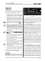
3.3.4 Input Connection
The balanced inputs have a nominal impedance of
10 K ohms (5 K ohms unbalanced) and will accept the
line-level output of most devices. Phone jacks are provided on the back panel, while the factory-installed
P.I.P.-FX provides female XLR input connectors (see
Figure 2.2). Optional P.I.P. modules like the P.I.P.-BB
and the P.I.P.-FPX can provide barrier block and
phono (RCA) connectors. Various P.I.P.s are also available which provide a wide range of input signal processing features (see Section 8).
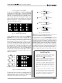
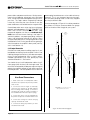
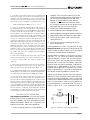
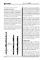
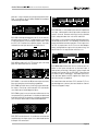
Correct input wiring depends on two factors:
(1) whether the input signal is balanced or unbalanced, and (2) whether the signal floats or has a
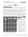
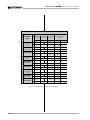
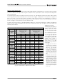
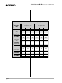
ground reference. Figures 3.8 and 3.9 show the recommended connection techniques for each combination
of source signal characteristics.
– +
– +
3
INPUT
Grounded
source
Output
1
2
Shield is not
connected
at this end
+
3-wire grounded line cord
(or other ground connection)
Twin-lead shielded cable
+
2-wire line cord
(or battery power)
– +
3
Floating
source
Output
1
2
+
2-wire line cord
(or battery power)
– +
3
INPUT
Grounded
source
Output
1
2
Input ground
terminal not used
+
3-wire grounded line cord
(or other ground connection)
Fig. 3.8 Unbalanced Input Wiring
Page 14
Single-conductor coax
or twisted pair
INPUT
Shield connected to both
negative (–) and ground
input terminals
2
–
+
2-wire line cord
(or battery power)
– +
3
Grounded
source
Output
INPUT
1
2
Shield not connected
at this end
–
+
3-wire grounded line cord
(or other ground connection)
2
Shield connected
to ground terminal
Floating
source
Output
1
Output
3
1
Fig. 3.9 Balanced Input Wiring
3
INPUT
– +
Note: If two or more channels with
the same input ground reference
are driven from the same
INPUT
floating source, connect
Floating
only one shield to the
source chassis.
source
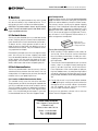
The amplifier’s built-in 1¦4-inch input phone jacks can
be wired similarly for balanced or unbalanced, floating
or ground-referenced sources. They have a standard
tip-ring-sleeve (TRS) configuration: the tip is positive
(+), the ring is negative (–) and the sleeve is ground
(see Figure 3.10). Wiring for various sources follows
the XLR wiring examples in Figures 3.8 and 3.9.
If you install a P.I.P. module other than the P.I.P.-FX,
P.I.P.-BB, P.I.P.-FMX or P.I.P.-FPX, do not connect input signals to the phone jacks. The phone jacks are in
parallel with the output of the P.I.P. module, so the
source connected to the phone jacks can feed into the
P.I.P. and generate a distortion in the output. The
phone jacks can still be used as “daisy chain” outputs
to feed the post-processed signal from the P.I.P. to the
input of other amplifiers.
If the amplifier will be used in Bridge-Mono or ParallelMono mode, be sure to follow the instructions provided
in Sections 3.3.2 and 3.3.3. Do not use the channel 2
input in either mono mode.
+
–
BALANCED
SHIELD
+
UNBALANCED
SHIELD
Fig. 3.10 Balanced and Unbalanced Phone Plugs