1
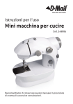
Owner's Manual
I CRRFTSMRN'I
SPRAY GUN
HLVP
High Volume
Low Pressure
Model No.
919.155190
•
Safety Guidelines
•
Operation
•
Maintenance
=
Storage
=
Repair
CAUTION:
Parts
Read the Safety Guidelines
and A+i Instructions
Operating.
Sears,
D29783
_ev_
Carefully Before
Roebuck and Co., Hoffman Estates, IL 60179 U.S.A.
visit our Craftsman website: www.sears.com/craftsman
04/26/04
Warranty .....................
2
Safety Guidelines - Definitions .... 2
Important Safety Instructions .... 3-4
Specifications
.................
4
Assembly ...................
5-7
Operation ..................
8-t0
Maintenance
.................
11
Troubleshooting
............
12-13
Parts List ....................
14
Spanish ..................
15-27
How to Order Repair Parts ........
.....................
back cover
r_l:1 :| :q:l _ ii'
FULL ONE YEAR WARRANTY
If this spray gun faits due to a defect in material or workmanship within one
year from the date of purchase, RETURN IT TO THE NEAREST SEARS
REPAIR CENTER THROUGHOUT THE UNITED STATES AND SEARS WILL
REPAIR IT, FREE OF CHARGE. If purchased from Orchard Suppty Hardware,
return to the nearest Orchard Store and Orchard wilt repair it, free of charge.
If this spray gun is used for commercial or rental purposes, the warranty wilt
apply for ninety days from the date of purchase.
This warranty gives you specific legat rights and you may have other rights
which vary from state to state.
Sears, Roebuck and Co., Hoffman Estates, IL 60179 U.S.A.
,_<l:lirii-i
[itljrl]
l!li_l 1{.I lll]lilllil[i]]{.l
This manual contaills [llforn_ation that is important for you to know and understated, This informatioll
relates to protecting YOUR SAFETY and PREVENTING EQUIPMENT PROBLEMS. TO help you
recognize this ii_fom_ation, we use the ayrnbols below, F'lee_e read the n_eJ_ualand pay attention to
these 8eotion_,
SAFETY and PREVENTING EQUIPMENT PROBLEMS= TO help you recog_ize this informatiom
use th_ syn_bols below. PFease _ead the m_nual eJhd pay attention to these sections,
_]ndicates
an
imminently
hazardous
situation which, if not avoided, will
result in death or serious injury,
which, if not avoided, _
result in
minor or moderate injury,
_]ndicates
_"_Ueed
hazardous
hazardous
a potentially
situation
without the
safety alert symbol
indicates a potentially hazardous
situation which, if not avoided, may
result in oroloertv damaae,
a potentially
situation
which, if not avoided, could
death or serious injury.
D29783
_[l_llndicates
result in
2-ENG
we
= SAVE THESE
INSTRUCTIONS
=
_
IMPROPER
OPERATION
OR MAINTENANCE
OF THIS PRODUCT
COULD
RESULT
IN SERIOUS
INJURY AND PROPERTY
DAMAGE,
READ AND UNDERSTAND ALL WARNINGS AND OPERATING INSTRUCTIONS BEFORE
USI NG THIS EQUIPMENT°
_The
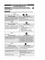
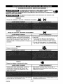
Following Hazards Can Occur During The Normal Use Of This Product:
HAZARD
Risk of explosion or fire - flammable materials
WHAT COULD HAPPEN
HAZARD
Risk of explosion
- incompatible
materials
WHAT COULD HAPPEN
HOW TO PREVENT IT
Read the label or data sheet for the material you
intend to spray°
1. Never use any type of spray coating material
containing these sofvents
2, Never use these solvents for equipment
cleaning or flushing
3_ If in doubt as to whether a material is
compatible, contact your material supplie_
The solvents 1,1,1 -Trichloroethane and Methyl.ene Chloride can chemicaliy react with the alu-.
minum used in most spray equipment, and this
gun and cup, to produce an explosion hazard
and could result in serious injury or death,.
i
......
HAZARD
Risk of breathing
L
WHAT COULD HAPPEN
I
HOW TO PREVENT IT
]
,_ii:i_?f_i
!!i::!
!i!-!'
iii_
i:_i.il
!!
!i!_
_i._!_!':!!_!'i::
:?_
:i!!!
_i_
!_!!
!__:!!:
!i:_!i!!!!i
:ii!!!!f:
:iii::/_!i:
iii_,!
_!:
::i!!I
:?i_
HAZARD
Risk of flying objects
HOW TO PREVENT IT
WHAT COULD HAPPEN
Certain parts are under pressure whenever the
gun is connected to a pressurized air lineoThese
parts may be propelled if the gun is disassembled
Disconnect the gun from the air line, or com_
pletely depressurize the air' line whenever the
gun is to be disassembled,
i!!ii!; ,iiii:
!?i!i!!ii
i! !i!iiiii!i
i!il; i! ;
:ii.gdggieS:i6_:_las_:w_en@ra_,!n_;_::i!_.":.i:_._i.h.'.:_i!:_.i.:.:-:._!,!::_.:::_:_.!:
Prolonged exposure to air spray can result in
permanent damage to hearing.
Always wear hearing protection when opera6ng
spray equipment..
, n H,,,
3- ENG
i,
, HH,
HAZARD
Risk of injection
WHAT COULD HAPPEN
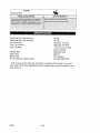
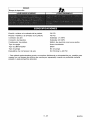
Minimum
Maximum
HOW TO PREVENT tT
Gun Inlet Pressure
Gun Inlet Pressure
20 PSt
45 PSI
Air Connection
Fluid Connection
Paint Canister
Standard
Standard
Needle
Stainless
1 Qt- Aluminum
Mouth Canister
Type
Feed Type
Bleed Type
Air compressor
Wide
Steel
Siphon*
Non-bleeder
Requirements
8.6 SCFM@4O
* This spray gun can easily be converted
with a paint tank (sold separately)
large projects.
029783
1/4 NPS
3/8 NPS
when
to pressure
spraying
,1_ ENG
PSI
feed mode to be used
heavy
bodied
material
or on
!:_..'_.:,]
=liv_
1=]li'il
Contents
of Carton
1- Spray Gun
1- Owners Manuat
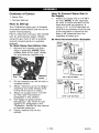
How to Set Up
Your Craftsman spray gun is shipped
completely assembled, and set-up for
siphon feed spraying.
Prior to shipment, this gun was treated
with an anticorrosive agent. Before
using this gun flush it with a suitable
solvent (mineral sprits is a suitabte
solvent).
To Flush Spray Gun Before Use
1. Removethe matehat cup from
lid/gun assembly. NOTE: Slide
release lever to the right, rotate
lid, and remove material cup.
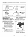
How To Connect Spray Gun to
Air Supply
t.
Attach air supply line to 1/4 NPT
air inlet. NOTE: A 318" diameter
air hose is recommended for the
best atomized air pressure. If
using a 1/4" or 5/16"diameter air
hose the air pressure must be set
at the regulator to allow for the
drop in air pressure from the
regulator to spray gun.
Air Hose Recommendation
lozzle
Examples
Air Hose
45 PSI
at air
lpprox.
_ply
at gun
3/8"
x 25 _ Air Hose
-
Recommended
10 I_i at
noz_e
Air Hose
45 PSi
at: air
APpr°x"
Cup
2.
3.
4.
5.
6.
1/4"
"Lever
Fill the material cup 3/4 full with a
suitabte sotvent.
Aftach material cup to the lid/gun
assembly and slide release lever
to the left to secure in pIaee.
Aftach air suppty line to 1/4 NPT
air inlet. See "Connection"
paragraph in this section.
Putt trigger to spray solvent
through gun, see "How TO Use
Spray Gun" paragraph in the
"Operation" section of this manual
to operate spray gun.
Empty material cup of any
solvent.
5-ENG
10 p;i at
nozzle
x 25 _ Air Hose
Air Hose
45 PSI
at air
Approx.
_i
;_t gun
5/16 _'x 25 _Air Hose
[:)29783
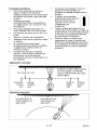
IMPORTANT: The use of a oiVwater extractor is recommended.
illustrations for exampIas.
See set
Basic Set Up
Air Inlet
_!
_
_
R?corameeded
_ir con_prsssor
equipped with
regulator
TO
Air Supply- ar_
r
Ideal Set Up
TO air s_lpply hard plumbed
air suppFy
Before
Using Spray Gun
This gun is designed
for use with most
finishing materials. It is not
designed for use with corrosive or
highly abrasive materials. Using
these materials can lead to poor
performance and/or failure of this
product.
1. Mix material according the
masufacturer's instructions.
Mixture should be smooth and
easity pourabIe. Lumps or foreign
particlas should be removed by
straining through a suitabte paint
fitter. NOTE: Using a Sears
Visceeimeter witl help in
measuring the viscosity or
thickness of the matedat.
2,
3,
Fill the material cup 3/4 full.
Attach material cup to the tidigun
assembly and slide release lever
to the left to secure in ptace.
NOTE: When repiacing iidigun
assembly make sure bend in matedat
tube is positioned to the front of the
spray gun as shown.
Bend
For Siphon Feed Connection
1. Removethe matedat cup from
lid/gun assembly. NOTE: Stide
release lever to the right, rotate
tid, and remove material cup.
D29783
4,
5,
6- ENG
Attach air supply line to 1/4 NPT
air inlet,
See "Operation" Section to learn
how to use the spray gun.
D29783
To Convert
Feed
to Remote
Pressure
If the material to be sprayed is too
heavy for siphon feed or higher
volume appIication is desired, convert
to the pressure feed set up,
1. Remove the material cup from
lid/gun assembly. NOTE: Stide
release lever to the right, rotate
lid, and remove material cup.
2. Siide yoke, with buiit in socket
feature, over nut. Grip the yoke
and turn to loosen nut, after the
nut is loosened hand turn untit tid
assembly can be removed from
gun.
3.
The gun is now ready to be
connected to any pressure feed
tank with a standard 3/8" straight
pipe femate connection. See
paint tank manufacturer's manuat
for correct procedure.
4. See "Operation" Section to tearn
how to use the spray gun.
NOTE: When replacing lid assembly to
gun assembly hand tighten nut and
then slide yoke over nut to tighten
securely.
Typical Pressure Feed Set Up
Regu_
Extractor
Oil/Water
To Air
Supply
Fluid Hose
7-ENG
D29783
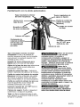
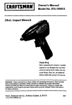
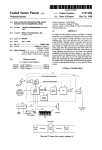
Know Your Spray Gun
Fluid Needle Adjustment
Machined Brass
Nut
Pattern Control
Air Car
__
Fluid Control
Knob
Hardened Steel
Fluid Tip
Release
Lever
1- Quart
Siphon Feed
Material Cup
1/4" NPT Air Inlet
Air Valve
Control Knob
Machined Brass External Mix Cap The air and material are mixed after
leaving the nozzle to provide a
superior finish with thick and thin
material
Hardened Steel Fluid Tip - for long
life.
Air Cap Horns - determines a
horizontal or veriical spray pattern,
Fluid Control Knob - controts the
fluid or density of fan spray.
Pattern Control Knob - controls the
size of the pattern from a targe oblong
to small round pattern,
Air Valve Control Knob - fine tunes
the material spray with air,
1t4" NPT Air Inlet- allows the spray
gun to be connected to the air supply.
Release Lever - releases tidigun
assembly from material cup.
Yoke - with built in wrench used to
easily remove gun from material cup
without tools.
D29783
_
Before
disassembly or removal of any part of gun or attached
components, shut off compressor,
release pressure by depressing
trigger, and disconnect power
source. NEVER assume system
pressure is zero!
_!]_
Prior to daily
operation, make
certain that all connections
and fittings are secure. Check hose and all
connections for a weak or worn
condition that could render system
unsafe. All replacement components
such as hose or fittings must have a
working pressure equal to or greater
than system pressure.
_TO
AVOID CREATING
AN EXPLOSIVE
ATMOSPHERE, WORK ONLY IN
WELL VENTILATED AREAS.
8" ENG
4.
F_q_,_
USE OF A FACE
MASK IS
RECOMMENDED TO PREVENT INHALATION OF TOXIC MATERIAL.
Before
Gun
1.
Air
Valve
Using Your Spray
Set up spray gun as described
in the "How to Set Up Spray
Gun" paragraph in the
"AssembIy" section of this
manual.
5.
To Use Spray Gun
1.
Turn air valve control knob
clockwise until it stops, do not
force.
The position of the air cap horns
wilt determine the fan spray
pattern. Loosen air cap and rotate
horns to achieve desired pattern.
Tighten air cap.
Horizontal
_
position
Vertical position
_DO
Adjust air pressure to 40 psi at
regulator.
psi.
NOT exceed 45
I_-_
Pressure may vary
according to
viscosity of material used. Maximum
working pressure of gun is 45 psi.
DO NOT EXCEED PRESSURE LIMIT
OF GUN OR ANY OTHER COMPONENT IN SYSTEM!
6.
2.
3.
Turn fluid control knob clockwise
untit it stops, do not force. This
wilt shut off the fluid flow. NOTE:
The fluid or density of "fan spray"
is contretied by fluid control
knob.
Turn pattern control knob
counteretockwise untit first thread
is flush with gun body. NOTE: Air
flew is contreIted by pattern control knob.
_DO
NOT turn pattern
control knob or fluid
control knob counter clockwise after
first thread is flush with the gun
body. They are under pressure when
the gun is triggered and could leave
the gun with force.
first thread flush
Pattern
Depress spray gun trigger and
gradually turn the fluid contret
knob counterclockwise until
desired fluid flow is reached.
Tngger gun quickly, one second
on-off to test pattern.
NEVER point spray
gun at self or any
other person. Accidental discharge
of material may result in serious
injury.
To adjust spray pattern and fluid
pressure:
•
TO adjust the fluid, turn fluid controi knob counterclockwise to increase or clockwise.
•
•
Knob
Ruid
To adjust the air flow, turn pattern
contret knob counteretockwise to
increase or clockwise to decrease.
To fine tune the air flew, turn air
vatve control knob counterclockwise to increase, or clockwise to
decrease.
IMPORTANT: Always clean gun after
each use. See "Maintenance" section
for correct procedure.
9-ENG
D29783
Don't are strokes, move the gun
paraiieI to work.
Pattern should be
shaped as shown, if not
see "Troubleshooting"
section.
Care should be exercised when handling spray gun to
avoid damage to the orifice of the
air cap and tip of fluid nozzle.
Damage to these parts results in
irregular spray patterns.
Practice on a cardboard target to
make sure pattern size and
material consistency are correct
before spraying on actual project.
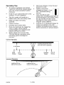
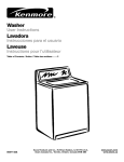
Operating Tips
To reduce overspray and obtain
maximum efficiency, always spray
with the towest possible fluid/air
pressure,
•
Hold the gun perpendicular
surface, 4_'to 6 _'distance,
•
Two thin coats witl produce a
better finish than one heavy coat,
Mask off areas not being
sprayed.
FoIIow contour.
•
•
•
•
•
to the
Overtap each stroke 50%.
Ends are feathered by triggering.
That is, begin stroke before
puiiing trigger and reieasing just
before ending the stroke•
Spray edges and corners first.
This witl reduce overspray while
providing good coverage on
corners.
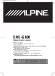
Correct Spraying
t
Coating should be even
and wet when spraying
4-6 inches
bJ--t
Start
Stroke
Incorrect
t ....
End of
Stroke
Spraying
I
coating wiiI be
light at this point
I
coating wiiI be
heavy at th+spoint
,
r
/'
,'J
I I
_ _ / / ,"
_] ] s /
Ilfl/I
II/,',"
. - -
,iJ
D29783
t
Release
Trigger
Pull
Trigger
S
•
e/z/,'
%%%
10+ ENG
,
_s
DO NOT ATTEMPT
TO UNCLOG (BACK
FLUSH) SPRAY GUN BY SQUEEZING
TRIGGER WHILE HOLDING FINGER
IN FRONT OF FLUID NOZZLE.
Always exercise extreme care when using any solvent or thinner. Never
clean gun near fire, flame, or any
source of heat or sparks. Properly
dispose of used cleaning materials.
DO NOT soak entire
spray gun in solvent
or thinner for a long period of time
as this will destroy lubricants and
possibly make motion uneven. NEV+
ER use lye or caustic alkaline solu+
tion for cleaning. Such solutions will
attack aluminum alloy parts of gun.
Cleaning
IMPORTANT: Clean gun immediately
after use. Paint and other materials
dry quickly in the small passages.
IMPORTANT: Do not immerse the
gun in solvent, this will cause
damage to the packings.
NOTE: Atways comply with local codes
when disposing of solvents,
6,
Remove air cap and immerse in a
suitabte solvent. Use a bristle
brush to clean dried paint and
btow it dry with compressed air.
7,
Use a wooden toothpick to clean
smalt ctogged hoies,
IMPORTANT: DO NOT use hard
objects to clean clogged holes.
The smallest amount of damage
may cause irregular spray
pattern.
8,
Wipe gun with a solvent soaked
cloth,
_'_
1.
2.
Turn off air suppiy to gun,
Remove the material cup from
lid/gun assembly. NOTE: Slide
release lever to the right, rotate
lid, and remove material cup.
When using the remote pressure
feed method: See manufacturer's
manual for suggested cleaning of
remote cup or tank.
3.
4.
5.
Empty matehat from matehat cup
and repiace with a suitable
cieaning soivent (see materia+
container for recommended
solvent).
Turn air suppiy on and operate
trigger untiJ ait mateha+ traces have
disappeared and gun is thoreughiy
ctean,
TO prevent corrosion, fi+imaterial
cup with mineral spirits, Turn air
supply on and operate thgger until
att traces of minerat spirits have
disappeared,
IMPORTANT: Make certain air cap
and fluid nozzle are kept clean at all
times.
Lubrication
Lubrication procedures must be observed after thoreughty cteaning the
gun to ensure effective, high quaiity
performance of spray gun,
t,
Lubricate working points with
straight mineral oit, or castor oil
2,
Pehodica+ly, place a few drops of
oil on tapered sections of fluid
nozzie to ensure easy operation of
air cap,
Replace nozzle set
When changing nozzte set, make sure
the eompiete nozzte set is exchanged.
A set inctudes an air cap, fluid nozzte,
and fluid needle. NOTE: Assemble
fluid nozzte before fluid needie.
11+ ENG
[329783
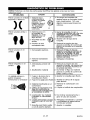
NOTICE: See parts fist
to identify parts referred to inthese Troubleshooting steps.
PROBLEM
4envy right or left side
3attarn
•
) t •"
_
4envy top or bottom
3attarn
ii
CAUSE
1, Dried material is
clogging side-
port
_ side-port
and spray
"B"
to"Ablow
causing
CORRECTION
A
1. Soak side-ports in thinner to
alean alog, DO NOT poke any
j
(_
towards the
clogged side.
opening with hard objects.
B
1, Dried material at
fluid nozzte "C
restricts air flow.
2, Loose air
nozzle.
c
/
/
/_--'_
1. Remove air nozzle. Wipe fluid
tip using a cloth soaked in a
suitabte solvent or a soft brush.
2. Fasten nozzte secarety.
3, Air pressure too
high
3. Turn pattern control knob
alockwise to reduce air
1, Too much matarial.
1. Turn fluid control knob
alockwise to decrease materia}
flow or turn pattern control
knob counter clockwise to
increase air pressure,
2. Thin material.
pressure.
9envy center pattern
2, Materia} too thick.
Sptit spray pattern
1. Air pressure too high,
2. Not enough material
Spitting, irregular or
luttering spray
1, Leak atthread of fluid
nozzte.
2, Leak at fluid needle.
pressure.
2, Turn fluid control knob counter
alockwise to increase material
flow.
1. Tighten fluid nozzle.
2. Tighten the fluid needle
adjustment nut.
3. insufficient fluid in cup.
3. Fii} cup with fluid,
4. Vent hole in matedal cup
cover clogged (only in
siphon feed [ned@.
4. Clean vent hole.
5, Mater_a} cup titled at an
excessive angle,
S. Do not tilt materia} cup
excassiveiy or rotate fluid tube.
6. Fluid too heavy for siphon
feed.
6. Thin material or convert to
remote pressure feed mode.
7. Tighten or replace.
7. Loose fluid tip or damaged
tip seat
D29783
1. Turn pattern control knob
alockwise to reduce air
12-ENG
PROBLEM
Unatomized or
spattered spray
CAUSE
CORRECTION
1. Material too heavy.
1. Thin material
2. Insufficient air pressure.
2, Turn pattern control knob
counter clockwise to increase
air pressure. Turn air valve
control knob counter clockwise
to increase air pressure.
3. Fluid pressure too high.
3. Turn fluid control knob
clockwise to decrease fluid
flow. If using in remote
pressure feed mode decrease
fluid pressure at paint tank.
4. Dried material on tip of
fluid nozzle or air jets of
air cap.
4, Clean.
1. Air valve control knob
partially closed.
1. Turn air valve control knob
clockwise to open.
2. Dried material in air jets
or air cap,
3, Obstruction in air inlst.
2. Clean.
1, Air pressure too high for
viscosity of fluid
1. Reduce air pressure at air
supply regalator, turn pattern
control knob clockwise, or turn
fluid control knob counter
clockwise,
2. Too far from work
surface.
2. Adjust to proper distance.
Material leaking from
fluid inlet of cup.
1, LOOSecup or foreign substances on!between cup
thread and fluid inlet.
1. Clean and tighten.
Material leaking from
nozzle when trigger is
1. Dried material in tip of
nozzle.
1. Clean
released
2. Loose fluid needle
adjustment nut.
2. Tighten fluid needle adjustment
nut,
Inadequate air
delivery
Excessive fog
13- ENG
3. Remove obstruction.
D29783
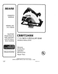
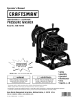
I ",?-'_
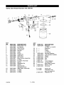
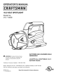
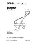
:J t_ B_..Sii
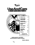
Spray Gun Model Number 919.155190
11
2 1
3
13
12
14
5
15 20 21
17
35
15 18
_7
25
KEY
NO.
1
2
3
4
5
6
7
8
10
11
12
13
14
15
16
17
18
PART NO
SG5-0056
SG5-0057
SG5-0058
SG5-0059
SG5-O060
SG5-0061
SG5-0062
SG5-0064
SG5-0066
SG5-0063
SG5-0021
SG5-0012
SG5-O010
SG5-0016
SG5-0024
SG5-0023
SG5-0025
19
20
21
22
SG5-OO20
SGS-OO17
SGS-OO18
SGS-OO19
D29783
DESCRIPTION
Brass Ring Cap
Air NozzJe
Fluid Nozzte
Air Reducer
Washer
Head
Screw
Trigger Pin
Snap Ring
Gun Body
Fluid Neadte Assembly
O-Ring
Air Valve Aseambly
Spdng
Retaining Nut
Spdng
Fluid Neadte
Adjusting Screw
Valve Stem Assembly
O-Ring
O-Ring
O-Ring
KEY
NO,
23
24
25
26
27
28
29
30
31
32
33
34
35
36
37
38
PART NO
SG5-0044
x
x
x
x
.....
.....
....
.....
SG5-0009
SGS-00O8
SG5-0013
+ SG5-0035
+ SG5-0036
+SG5-0037
+ SGE- 15
+ SG5-0039
+
+ SG5-0041
+ SG5-0042
• K-0189
+ K-0190
x SG5-0051
14-ENG
DESCRIPTION
Adapater 1/4 NPT x 1/4 NPS
Regutater
Screw
O-Ring
Lock Ring
Packing, Retainer
Ftuid Needle Packing
Trigger
Screw
Nut
Arm
Lever Release
Lid Cannister
SG5-0040 Gasket
Siphon Tube
Cannister
Gasket Kit.
Complete Cup
and Ud Assembly
Regulator Kit
Garantfa .........................
Defi_iciones de normas de seguridad
15
....
15
lnstruooiones importantesde
seguridad .....................
Especificaciones
..................
16-17
17
Ensam blaje
18-20
...................
Operacibn
....................
Mantenimiento
...................
21 _23
24
DiagnSstico de probiemas ..........
Lista de partes ...................
Come solicitar
repuestos
....
25
14
contratepa
[_,-! -'f',-!#kilF-1
UN AI_O DE GARANTIACOMPLETASOBRE LA PISTOLAROCIADORA
Si esta pistola reciadora tuviera falias de matsriales o fabdcaci6n dentro del ass de su fenha de
compra, DEVU_LVALAAL CENTRODE REPARAC[ONESDE SEARS M_,SCERCANO DENTRODE
LOS EE.UU., Y SEARS LA REPARAF_SIN CARGOALGUNO. SI SE HUBtESECOMPRADO EN
UNA PERRETER[AORCHARD, DEVU6LVALAA LA FERETERAORCHARDM_q CERCANA, Y
ORCHARD LA REPARARASIN CARGO ALGUNO.
Si esta pistola reciadora fusra utilizada pars uso comereiaJo con prop6sito de alquilsr, la garar41s
tendrA vigencia solamente pot noventa dias a pa_r do lafechs do somp(a.
Esta garantls le otorga derechos legales especlficos y usted podrra tener otros derechos qua varran
entre los estados.
Sears, Roebuck and Co., Hoffman Estates, IL 60179 EE.UU.
Este manual contiene informaciSn que es importante que usted sepa y entienda. Esta
informaci6n se relaciona con la protecci6n de SU SEGURIDAD y la PREVENCION DE
PROBLEMAS AL EQUIPS. Para ayudafle a identiflcaresta infonnaci6n usamos los
siguientes simbolos. Per favor leer este manual y prestar atenci6n especial a estas secoiones.
_
indica una situaci6n de
riesgo inminente que si
no se evita eausar& lesiones serias o
mue_e.
_
Indica una situasiL, n
potencialmente
peligrosa, que si no se evitada, podrfa
causar lesiones meneres o moderadas.
potensialmente
riesgosa, que si no as
ev_a podr_ causarlesiones
sedes o
mue_e,
_
Usado sin el sfmbolo
de seguridad de
aterta, indica una situasi_,n pofensialmente
riesgosa que si no se evita, podria causar
dahos en la propieded,
15-SP
D29783
I 11t.____ililit Ill 11ict II_1]I,] ;it:l _i i tC_lilt_ll
;] rn.,_,]
• CONSERVE ESTAS INSTRUCCIONES
•
LA OPERACION INAPROPIADA DE ESTA UNIDAD PUEDE CAUSAR
_
LESIONES SERIAS Y DAI_OS A LA PROPIEDAD. LEER Y
ENTENDER TODAS LAS ADVERTENCIAS DE SEGURIDAD E INSTRUCCIONES DE OPERACI(_N :
ANTES DE USAR ESTA UNIDAD.
_
Los siguientes riesgo_ pueden ocurrir duranie el uso normel de este
producto:
Riesgo de explosi6n
o incendio - Mat_riales
Riesgo de exp]osi_
RIESGO
- Mate_ales
inflamables,
__
incompatibles
&QUE PUEDE OCURRIR?
&C_)MO PREVENIRLO?
LOS solventes 1, 1, 1 - T_cloroet_nos y Clor_iro
de M_tilei_o pueden reacciona_ qulmicamente
CO_ el _un_inio qLie se usa er_ la rnayo_i_ de los
equipos de pulverizaci6n en esta pistola yen
me coi_tei_edo_ y ptleden generar ur_ 4esgo de
explosi6n.
Leer I_ etiqueta u hoja de ir_formaci6n del mate4_i
a ptilvefiz_¢,
1 ,Nunca _isa_ti_ alguno de I_ca protecto_
ptilve4zable que cor_tenga estos _olven±es.
2,No user e3tos solventes pa_ fl_npi_r e] equipo.
3,Ei_ caso de duda respecto a I_ con_patibilidad
del m_te4_J, contactar _J p_oveedor del _eri_l,
RIESGO
Riesgo de inhalation
&QUE PUEDE OCURRIR?
RIESGO
Riesgo de objetos ell suspension
a_tea
&QUE PUEDE OCURRIR?
&C_MO
PREVENIRLO?
Ciertas partes est_n presurizadas cLi_ndo la
pistola est_ conectada a una I_i_eade aire
p_sLinz_da y pueden salir dispar_das si se
de_3rma I_ pistol&
Desconectar la pistola de la If=_eade aire, o
despres_rizarla completamel_te cuar_do se vaya
a desam_a_ la pistol&
La exposici6n p_olo_gada al choffo de aire puede
causa_ lesiones peril_ane_tes _11o{do,
/%1operar un equipo papa pulverizar sierapre usar
piotecci6n para los oidos.
D29783
16-SP
Riesgo de lnye_cibRn IESGO
_,_
Presi6n minima a la entrada de la pistoia
20 PSI
Presi6n mc_bximaa ta entrada de ta pistola
Conexi6n de aire
45 PSI
Conexi6n de liquldos
Estandar 3/8 NPS
Contenedor
Est_dar
de pintura
1/4 NPS
946mt, de aluminio con boca ancha
Tipo de aguja
Acero inoxidabfe
Tipo de alimentaeion
Sif6n*
Tipo de purga
Requisitos
deI compresor
NO se purga
8.6 PieVmin a 40 PSi
de aire
* Esta pistota pulverizadora puede convertirse facilmente a atimentaei6n por presi6n para
usarse con un tanque de pintura (se vende pot separado) euando se putveriza material
pesado o para proyectos grandes.
17-SP
D29783
1:4__;'1__I
iV_l
=1Ilr:!!]_
Contenido
de la caja
1- Pistela pulverizadera
1- Manuiat del propietario
C6mo armar
La pistola puiverizadora Craftsman se
despanha eompletamente ensambtada y
preparada para putverizar atiment&ndose
per sif6n.
Esta pistota fue tratada con un
antieorrosivo antes de su despaeho, per Io
que antes de usarse debe lavarse
intemamente
con un solvente apropiado
(destilado mineral).
Pata lavar intemamente
de su use
Come conectar
la pistola
pulverizadora
al suministro
de airs
1.
Conectar la linea de suminlstro de
aire at conector de entrada de 1/4'
NPT. NOTA: Para la mejor presi6n de
aire para pulverizar, se recornienda
usar una rnanguera de 3/8" de
dit_metro. Si se usa una manguera de
aire de 1/4" 6 5t16" de dl_{metro, ta
presi6n de aire debe graduarse an el
reguiador para cornpensar per la
cafda de presi6n de aire entre et
regulador y ta pistota pulverizadora.
la pistola antes
Ejemplos de recomendaciones para
manguera de airs
) 81 en
MangLISra
a boqt lilla
de _ire
45 p$1 en _1
_um!nisbo
_0rox.
I0__
Caida d_ ai_
en la pi_a
Manguera
de
3/8 _ x 7,6m
de seguro
1.
2.
Desmontar et contenedor de la tapa
an la plstota. NOTA: Desllzar la
palanea a ta deranha, rotar ta tapa y
desprander el contenedor,
Lienar 3/4 partes del contenedor
un sotvente adecuado.
Man.era
Ill all
st _rr_nistt_
con
Caid_
4.
Conectar la tfnea de suministro de
aire al eonector de 1/4" NPT.
Referirse al p_rafo "Conexi6n"an
esta secci6n.
_e ilire
en la pistola 16 PSi
Manguera de airs de
t/4" x 7,6m {25')
PSi en la
Mangtzet_
boqtlilla
de airs
45 PSI _._ el
sumiai_
Apretar el gatitlo para disparar et
solvente y que pase per la pistola.
Referirse al p_rafo "Come usar la
pistola pulverizadora' en la secci6n
"Operaci6n" de este manual.
C;_ld_[
;
,
-
,
Manguera de airs de
5/16" x 7,6m (25')
Putverizar todo et solvents basra que
se agote y evacuar eualquier residue
del contenedor.
D29783
PSI In la
Ixlqliilla
AWOx. II_
Reinstalar el contenedor en la tapa an
la pistola y deslizar la palanca a ta
izquierda para asegurar el
contenedor.
6.
de
(25')
45 PSI en 81
3.
5.
3 PSI
airs
18-SP
tMPORTANTE:
itustraciones,
Configuracibn
Se recomienda
usar un extractor de _ceitei_gua.
Ver los ejemplos en las
bdsica
B_trad_ de aire
surainist_ode aire
(Un corap_esor
equipado con ui_
regulador)
Extractor de
aceite!_gLia
Configuracibn
ideal
A la linea de
surninist[o de
aire (concalda
fuerte de
pre_i6_!
Regulador y extractor
de aceite!agLia
Antes de usar la pistola
pulverizadora
3.
usarse cen la mayeda de matedales para
acabados que no sean corrosivos o
altamente abrasivos; ya que (_stos
producirfan un real rendimiento yfo la
falla de la pistola.
NOTA: At reinstalar la pistola, cerciorarse
que el doblez en el tubo del sifOn quede
hacia el frente de ta pistoia como se
muestra.
1.
Para
Mezclar d m_terial sigu_ndo las
insfrucciones del fabricante, La mezcta
debe quedar sin grumos y debe poderse
vaciar f&cilmente. Deben etiminarse los
grumos y particulas extrabas col&ndose
con un filtro de pintura adecuado,
NOTA: El uso de un meclidor de
viscosidad de Sears ayudar_{ medir ta
viscosidad o espesor del material
conexibn
con alimentacibn
pot sifbn
1,
Desmontar el contenedor de la
pistol& NOTA: Deslizar la palanca a
ta derecha, rotar ta tapa y desprender
el contenedor.
2,
Reinstalar et confenedor en la tapa en
la pistola y deslizar la patanca a ta
izquierda para asegurar el
contenedor.
Llenar 3/4 partes del contenedor
un solvente adecuado.
Debits
4,
Conectar ta Ifnea de surninistro de
aire al conector de 1/4" NPT
5,
Para aprender a usar la pistola
pulverizadora, referirse a la secci6n
"Operaci6nL
con
19-SP
D29783
Para convertir
a alimentaci6n
remota a presi6n
Si el material a pulverizarse fuese muy
pesado para atimantaei6n per sif6n o se
desea apticar una mayor cantidad de
vo}umen:
1.
2.
Desmontar el contenedor de la
pistol& NOTA= Deslizar ta palanea
a la derecha, tatar la tapa en ta
pistoia y desprender ef contenedor,
DeslJzar el yugo con el adaptador
incorporado sabre la tuerea. Agarrar
et yugo y girarlo para aftoiar la tuerca
y gJrar a mane basra queet conjunto
de ta tapa pueda sacarse de la
pistota,
3.
4.
Ahora la pistola est,{ lista para
conectarse a cuatquier tanque para
aiimentacion a presi6n con un niple
hembra, estAndar recto de 3/8". Para
et proeedimiento correcto, referirse al
manual del fabricante det tanque.
Referirse a ta secei6n "Operaci6n °
Data aprender a usar la pistola
puiverizadora.
NOTA: AI reinstalar el conjunto de ta tapa
en la pistola, ajustar a mane ta tuerea y
deslizar el yugo sobre la tuerca para
ajustarla firmernente.
Configuraci6n
tipica alimentacibn
remora a presi6n
Regu_
aceite/agua
Extractor de
AI
=ll_suministro
de aire
Manguera
D29783
20-SP
de I|quido
Familiarizaci6n
con la pistola pulverizadora
Tapa mezcladora exterior
de latbn maquinado
Tueroa reguladora
de
Perina de control de
Aletas de la
tapa de airo
(Abanico)
.Perilla de control
del flujo
Boquilla de liquido
de acero endurecido
Palanca de seguro
Contenedor de
material de 946ml.
(1/4 de Gal.} con
de alimentacibn
por sribn
Tapa mezcladora
exterior de latbn
maquinado. Et aire y el material se
mezdan despu6s de satir pot la boquilta
para proveer un acabado superior con
material grueso o fino.
Boquilla de acero endurocido para
liquido para una vida _il m&s larga.
Aletae de la tapa de aire para seleccionar
entre un patr6n de rociado (Abanico)
horizontal o vertical.
Perilla de control del flujo, Controla la
fiuidez o densfdad def abanico de rociado.
Perilla de control del patr6n de rociado
(Abanico) Controla el tamar_o del patr6n
de rociado o abanico desde una forrna
targa ovoide basra un un circulo pequefio.
Perilla de control la v_lvula de airo para
hacer el ajuste fine de la mezcia de
material pulverJzado con el aire.
Conector roscado de 1/4" NPT para la
tinea de suministro de aire,
Palanca de seguro. Suetta o asegura eI
contenedor a ta tapa en la pistola.
de 1/4" NPT para
entrada de aire
V_lvula de aire
_
Antes de desarmar
o de sacarie
cualquier pieza a la pistola o
componentes instalados, apagar el
compresor, deepresurizar apretando el
gatino y desconectar de la fuente de
energia, iNUNCA asumir que el sietema
eat& deepresurizado (presi6n cero).
cerciorarse que todaa lae conexiones y
acoples eetdn apretados firrr_mente.
Inapeccionar la manguera y todaa lae
conexionee para detectar si hay partee
d/_biles o gaetadaa que puedan volver el
aistema inseguro. Todos los
componentes de repuesto como
mangueraa o acoples debea tener una
capacidad de trabajo igual o mayor a la
preeibn del eistema.
_PARA
ffVITAR
CREAR UNA
ATMOSFERA EXPLOSIVA, TRABAJAR
SOLO EN AREAS BIEN VENTILADAS.
Yugo con Itave Jncorporada que se usa
para separar el contenedor f_{cilmente de
ta tapa en la pistola.
21-SP
D29783
4.
MASCARA PROTECTORA PARA EVlTAR
INHALAR MATERIALES TOXICOS,
Antes de usar la pistola
pulverizadora
1.
1.
Pcrilla de
control de
Arrnarl8 orno se indica en el p_rafo
"Armado de I_ pistola pulverizadara"
en la secci6n "Enssmblaje",
Para usar la pistola
Girar la peritla de ta vAivula de aire en
et sefltido del retoj hasta que se
detenga, no forzarla.
de aire
pulverizadora
La posici6n de las atetas de la tapa
de aire determina et patron del
abanico de rociado, Aflojar ta tapa de
aire y girar las atetas para obtener el
patr6n deseado. Volver a ajustar la
tapa de aire,
5.
_NO
Graduar el regular para una presi6n
de aire de 40 PSI.
exceder
45 PSI.
a la viscosidad dcl material utilizado. La
presi6n m_xirna de trabajo de la pistola
es 45 PSI, iNO EXCEDER EL LIMtTE DE
PRESION DE LA PISTOLA NI DE
COMPONENTE ALGUNO DEL SISTEMA!
Posici6n horizontal
_
2.
3.
Posici6n vertical
Cortar et flujo girando la petilla de
control del flujo en el sentido dci
reloj hasta que el flujo se detenga, sin
forzar. NOTA: La fluidez o densidad
del abanico de rociado se controta
con ta perilia de control del flujo.
Girar ta perilla de control de patrbn
contra el sentido del reloj hasta que
la primara vuelta de la rosca este a
ras con el casco de la pistol& NOTA:
El flujo de aire se controla con la
perilia de control del patrbn,
NO girar la perilla
de control del
patrbn ni la del control de fluido contra el
sentido del reloj despu_s que la primera
vuelta de las roscas est/_n a ras con el
casco de la pistola; porque cst_n
presurizadas cuando se apricta el gatillo
y podrian salir dispamdas con fucrza.
Primera rosca a
Pcrilla de
control
Perilla
control
del
flUlO
D29783
6.
Aprctar el gatillo y girar graduatmente
la perilta de control de fluido contra et
sentido del reloj hasta Iograr el flujo
de tiquido deseado. Probar el patr6n
(abanido) de rociado, apretar et gatillo
con una intermitencia de un segundo.
_
Nunca apuntar la
pistola
pulverizadora a si mismo ni a otras
personas porque una descarga
accidental podrfa causar lesiones
serias,
Para regular
el patr6n de rociado
y
presibn de fluido:
Para regular ta presi6n del tfquido,
girar la perilla de control de fluido
contra et sentido det retoj para
aumentarla o en et sentido det reloj
para disminuirla,
Para regular et flujo de aire, girar la
perilla de control dci flujo de aire
contra et sentido det retoj para
aumentarla o en et sentido deI reloj
para disminuirla,
Para ta regulaci6n fina dot flujo de
aire, girar la v&lvuia de control de aire
contra et sentido det reloj para
aumentarlo o en et sentido del retoj
para disminuirlo.
IMPORTANTE: Siemprc lirnpiar la pistola
despu&s de cada uso. Refarirse a la
secci6n "Mantenimiento"
para et
procedimiento correcto,
22-SP
Consejos
prbcticos:
No arquear }aspasadas, mover {a
pistola en forma paraiela a {a
superfisie de trabajo durante toda ta
pasada.
Et patron de pu{verizado
normalmente debe tenet ta
{orma mostrada; de 1o
contrario vet la secci6n
"Diagn6stiso de
Problemas".
Para svitar pulverizar _ sxceso y
tograr el m&ximo de eficiencia,
siempre puiverizar con ta combinaci6n
de presi6n de pintura y airs m&s baja
posib{e.
Sostener {a pistola
perpendisutarmente
a {a superfisie a
una distancia de 10 a 15 crn (4" a 6"}
de distancia.
Tratar la pistola pulverizadora son
cuidado para evitar dafiar el orifisio de
{a tapa de airs y de la boquilta; porque
si se da_an, se producir&n patrones
de pulverizaci6n irregulares.
Practicar sobre un cart6n para
asegurarse de lograr el tama_o det
patr6n de rosiado (abanico) corrects y
{a consistensia de material adecuada
antes de pintar ta rociar ta superficie
definitiva.
Dos capas delgadas proclusen un
msjor acabado que una ca43a gruesa.
Enmascarar las 9zsas que no se van a
rooiar.
Seguir el contorno de {a superficie.
Trasiapar sada nuevo pass 50% sobre
el anterior.
E{ movimiento del pass debe
empszarse antes de apretar el gatillo y
el gat{lto debe sottarse antes de
terminar el pass.
Pulverizar los hordes y esquinas
primers. Esto redusira et excess de
pulverizado, asi cams tambi6n
proveerQ de un buen recubrimiento en
tas esquinas.
Aplicaci6rt
correcta:
AI aplicar un pass, debe hacerse
en forma pareja y el materia}
rosiado anteriormente non debe
10a 15cm (4 _ a6")
estar mojado.
bL-t
Comenzar
el pass
aqui
Aplieaei6n
t.... t
Sottar et
gati{Io
aqui
Apretar
e{ gatil}o
aqui
Terminar
el pass
aqui
ineorrecta
I
Recubrimiento de
menos espesor en
este punts
i
: ,' ,,"k
Recubrimiento de
m&s espesor en
este punts
[ / / /" ,'"
!
•
[ _ / ,." ,."
I1
/
s
[ i s//
23-SP
,'"
i//-.,
D29783
hV_lr.'_l_
Ji:i_l ILvJI1
:l_i I[_]
_NO
INTENTAR LA
DESATORAR
PISTOLA APRETANDO EL GATILLO Y
TAPANDO LA BOQUlLLA CON EL DFDO.
cuando se usen solventes o diluyentes.
Nunca lirnpiar o lavar la pistola eerea de
fuego, llamas rti faentes de ealor o
ehispas. Deseehar apropiadamente
los
materiales ueados err la limpieza o
]avado.
per largo tiempo porque se destruir_ su
]ubrieacibn y posiblemente su
accionamiento
se vuelva irregular.
NUNCA usar lejla ni soluciones alcalinas
al limpiar (lavar) la pistola porque esas
solueJones atacan las plazas de aleacibn
de aluminta.
Limpieza
o Lavado
IMPORTANTE: Limpiar (lavar) la pistola
inmediatarnente despuds de eada use.
LB pintura y otros materJales se secan
rbpidamente
en los pasajes peque_os.
1.
Cortar et suministre de sire a la
pistola.
2. Deseonectar e_conteneder de
material de la tapa en Is pistola.
NOTA: Deslizar ta palanca a la
derecha, rotar la taps en la pistols
y desprender et contenedor. Cuando
se use el m_todo de alimentaei6n
remota a presi6n, refedrse at manual
del fabrieanta pars las sugerencias de
limpieza (lavado) del contenedor o
tanque.
3.
Vsciar et material det contenedor y
reemplazarto con un tiquido solvente
adecuado (pars et solvente aprepiado,
referirse a }aetiqueta del envase del
material).
4.
Abrir el surninistro de aire y apretar el
gatillo hasta que desaparezca toda
traza del material y ta pistota quede
comptetamente Iimpia,
5.
Pars evitar la corrosion, llenar et
contenedor con un destiiado
mineraI,Abrir el suministro de sire
y apretar el gatilio hasta qua
desaparezea toda traza del destiiado
mineral,
D29783
IMPORTANTE: No sumergir la pistola en
el solvente porque las empaquetadures
se dafiar_n.
NOTA: Siempre acstar tos e6digos locales
at desechar los solventes,
6.
Saear la taps y sumergirta en un
sotventa adecuado, Usar una escobilla
de cerdss pars tirnpiar Is pintars seca
y sop[aria con airs eomprimido,
7.
Usar un pstiIIo escarbadientes
de
readers pars timpiar }as obstrucciones
de tos erificios peque_os.
IMPORTANTE: No usar objetos duros
pare limpiar las obstrueciones de los
orificios, porque el da_o m_s lave puede
eausar an patrbn irregular de rociado.
8.
Limpiar _a pistela fret&qdota con un
par3e empapado en selventa,
IMPORTANTE: Cerciorarse de mantener
siempre limpias la tapa de aire y la
boquilla para Ifquidos.
Lubricacibn
Pars asegursrse de msntaner la calidad del
alto rendirniento de _apistols pulverizadora,
despues de cads limpieza (lavado)
complete, siempre seguir el procedimiento
de lubricaci6n.
1.
Lubriear tos puntos de movimiento
con sceite miners{ pure o aseite de
csstor,
2.
Apliesr peri6dieamente unss gotas de
aeeite en las secciones ahusadas de la
boquiils pars iiquidos pars asegurar su
funcionamiento f_ci{ de la taps de sire.
Reemplazo
boquilla
del conjunto
de la
Cuando se eambie e{ conjunte de {a
boquilla, eerciorarse de cambiar todos sue
componentes. Et eonjunto est6 eompuesto
per la tapa de aire, }a boquitta para liquidos
y Is aguja pars liquidos. NOTA: Ensamblar
la boquilla psra Ifquidos antes qua la aguja
pars tiquidos.
24-SP
NOTA: Referirse a la lista de partes para identiticar
referencia aaul
CAUSA
PROBLEMA
Patr6n grueso en el lade
izquierdo o derecho.
)(
Patr6n grueso arriba o
abajo.
Patr6n grueso en el
centre.
I
tas plazas a tas qua se hace
CORRECCION
1, Material seco
1. Sumergir los boquillas de
ambos lades en so}vente limpio
para desatorarlas.
NO usar
objetos duros para limpiar los
erifialos,
A
orificio de salida
del lade "A"
haciendo qua at
orificio
del lade
obstruyendo
el
"B' pulveriee
hacia et lade
obstruido.
@
1, Material seco en
ta boquilla de
liqaldos "C" est_
restringiendo
el
flujo d_ alre.
2, Boqalltas de alre
sualta.
3, Presion de aire
demasiado alto
B
c
/
/
(_)_
1, Demasiado material.
2, Material demasiado
1. #ac_r la I_ogalll_ de alrey
I_mptarla trotbngola egn una te_a
em
a COn un solvent
ad"&" 24
oconona
e gi,a
de cerdas blandas
2. Ajustar bien la tapa de la
boquilla,
3. Reducir ta prealon de aire
girando la peritla de control del
patr6n de rociado en et sentido
dal tel@.
1. Reducir el flujq_de Ifquido
g r_pdo a per _le pqntro de
TiUlaOen el sentlao eel relo31o
aymentar la presi6n de alrd
gtr#r)do ]_ pej'i}l_ de qontrol del
patr#n (A,b_mgq) contra el
senttdo clet reloj.
2. Adelgazar el material•
espeso,
Patr6n angosto
en el
1. Demasiada presi6n de
alre
2. Insufieientemateriel
centre.
I
[a pistola escupe o
Fotr6n irregular,
tembloroso u onduiado
1. Reducir ta presion de aire
girando la peritla de control del
patr6n de rociado {Abanico) en
et sentido del retoj.
2, Aumentar et flujo de material
girando la peritla de control de
ftuido contra et raloj
1, Fuga en la rosca de la
boqallta para flaldo
2, Fuga en la aguja para fluido
1. Ajuster la boquilta para fluido..
3. Material insuf_alenteen e!
contenedor.
3. Raltenar el eontenedor con
Ifqaldo
4. Limpiar el orificio de respiraci6n
4. Odfielo de resp_aci6n en la
tapa det contenedor de
material e_t& obstruida (s_o
en modaJidad de sit(an).
2. Ajustar ta tuerca de ta aguja
para fluidos.
5, Contenedor de material
inclinado en demasiado
_{ngalo,
Uquido demasiado espeso
6. o ¢esado para el tube dal
5. No inelinar excesivamente
girar at tube de succi6n.
7. Boqaltia para fiuido suelta
o con el asiento dafiado.
7. Ajustar o eambiar.
25-SP
o
6. Adelgazar el material o cambiar
a modalidad de alimentaci6n
remora For presion
D29783
PROBLEMA
Material rociado no
pulverizado o
salpicado,
CAUSA
CORRECCION
1. Material demasiado
pesado o espeso
2. Presi6n de aire
insuficiente.
3. Presi6n de fluido
demasiado alta,
4. Material seco en el
orificio de la boquilia de
fluido o fugas de aire per
la tapa de'aire.
Salida de aire
inadecuada.
1. Per#In de eontroi de la
vaivuta de aire
pareiatmente
Nebutizaei6n
excesiva.
cerrada.
1. Adelgazar el material.
2. Aumentar ta presi6n de aire
girando ta perilta del patron
[Abanieo) eontra el sentido det
reloj. Aumentar la ,oresi6n de
aire .£1irandota perilta de la
v_{Iv_la de aire centre el
sentido del retoj,
3. Redueir et flujo de liquido
girando la peritla de control del
flujo en el seniido clet reloj. Si
se est_ usando con
alimentaei6n remora a presi6n,
disminuir la presi6n del liquido
en et tanque de pintura.
4, Limpia_
1. Abrir la periila de eontrot de la
valvula de aire gir&ndola en el
sentido del retoj
2. Material seco en los
orificios de saiida de aire
o la tapa de aire.
2. Limpiar.
3, Obstrucci6n
de aire.
3. Eliminar {a obstruccion.
en la entrada
1. Demasiada presi6n de
aire para la viseosidad
det liquJdo.
1. Redueir la presJ6n de aire en el
regutador, girando la perilta de
control det patr6n en et sentido
det retoj o girando ta perllla de
control de fluido contra el
sentido det reloj.
Fuga de material For la
entrada det eontenedor.
2. Aplicaci6n desde muy
lejos de ta superfieie.
2. Aplicar desde una distancia
adecuada.
1, Et contenedor
1. Limpiar y ajustar.
est& suelto
o hay substancias
extrar3as entre la rosca
det eontenedor y la
entrada de Ifquido.
Fuga de material For ta
boquilla euando se
suelta el gatillo.
1. Material seco en el odficio
2. La tuerea de ajuste de la
aguja de fluidos est,{
suelta.
D29783
1. Lim piar
de la boquilta
26- SP
2. Ajustar la tuerca de ajuste de la
aguja de fluidos.
I_l]i_..-]
27-SP
D29783
D29783
28-SP
29-SP
D29783
D29783
30-SP
3_-SP
D29783