1
USOO5757890A
United States Patent [191
[11] Patent Number:
[45] Date of Patent:
Venkatakrishnan
[54] DATA LINK FOR MULTI-PLAYER GAME
SYSTEM USING TELEPHONE LINES
5,757,890
May 26, 1998
Primary Examiner—Curtis Kuntz
Assistant Examiner?stephen W. Palan
_
Attorney, Agent, or Firm—Phi1ip H. Albert; Townsend and
[75] Inventor: gzlilfesan Venkataknshnan. Fremont.
Townsend and Cmw
[57]
ABSTRACT
[73] Assignee: Phylon Communications, Inc..
Fremom Cami
[21]
An improved data transfer system is provided to transfer
game data over a telephone line with low delay even while
a voice conversation is being transferred over the same
APPL NW 566,988
_
telephone line. Voice data and game data are framed. in a
[22] Flled:
[51]
[52]
Dec‘ 4’ 1995
modi?ed HDLC framing scheme. with game data inserted.
Int. Cl.l5 .................................................. .. H04M 11/00
US. Cl.
. . ..
379/9313; 379/9331;
if “3668mm into a mum which contains ‘mica so that the
time need/661110 complete the frame 15 not added to the delay
379/9109; 379/493
of the game data. The inserted game data need not be of a
[58} Field of Search ............................ .. 379/9001. 93.01,
?xed "mg‘h' as ‘t ‘8 Clem?“ “"th“? ‘ht "we dam Py 3“
379/9108. 93.09. 93.13. 93.31; 463/41;
6s°aPe.seq‘fe“°e 9°‘ f°““d 1“ Fh? “m m" “1° ava?abk
455/6} 348/17_ 370/442. 493“ 498 528_
bandwidth 15 ef?ciently used since frames of voice data are
’
’
37‘5/222’
not necessarily sent during periods of silence and frames of
game data or other data can be sent using the entire tele
[56]
References Cited
phone line bandwidth. The data is framed at a point beyond
the output of pre-existing games and data transfer programs.
U.S. PATENT DOCUMENTS
to allow for transparent insertion of voice into the frame
4,570,930
stream.
2/1986 Matheson ........................... .. 379/9313
5,463,616 10/1995 Kruse et a1. .
5,502,727
3/1996 Catazaro
.
379193.08
379/9308
11 Claims, 6 Drawing Sheets
24
i.'
26
30
, _______________
""""""""""""""""""""""""
_ ._Analon_<3allwailtng_?xpasa ................. _.__
|
1
|
l
{
f
50
6"
Voice
CODEC
|
'
:
I
:,
DATA
‘
52
HDL°
INTERFACE <—{———o
____ ‘gigital """""""""""
98." Wailing Bypass
"!
framer/
[11%
!
!
54
i
02:11:16
'
I
t
Ii
:
|
::
i
s
58
I
i
,
' 66
':
g‘
AFE
I
(RS232, etc.)
|
from Computer
:
I
:
Frame
i
:
Storage
1
System 20
def'ame'
i )2
:
I
62
60
DAA
|
:
|
l\ ____ _ _ _ _ _
_ _ _ _ _ _ _ _ _ _ _ _ _ _ _ _ _ _ _ _ _ _ _ _ _ _ _ _ _
_ _ _ _
ll
40
Image CODEC
32
34
TELEPHONE
LINE 16
41
H
'
out“!
mage
42
can
’
‘
t
S
llllllilliillilliglllll
akers
p6
CCD CAMERA
MIDI
Abort Flags
Frame
Hag
Game
Voice Data
Data
.
Voice Data
Frame
Hag
_.
PIayLinkTM Frame (2nd mode, variation 2)
US. Patent
May 26, 1998
Start
Flag
Address
Sheet 4 of 6
Control
Data
5,757,890
FCS
End
Flag
Fig. 4 HDLC Frame (1st Mode)
Start
Voice Packets
Flag
Abort
n-byte data
Voice
End
Flag
packet
Packets
Flag
Fig. 5 Modi?ed HDLC Frame (2nd Mode, variation 1)
Abort Flags
Frame
Flag
.
Vo|ce Data
Game
Data
.
volce Data
Frame
Flag
Fig. 6 PlayLinkTM Frame (2nd mode, variation 2)
US. Patent
May 26, 1998
Sheet 5 0f 6
5,757,890
Start
Pause In Voice
Signal
'
No Voice Data
Present
Wait for
Game Data
Check if
Voice Data is
or Timeout
Present
Game
‘
33
Voice
Data
Data
Received r
V Present
S4
Send Game
Data Packet
Game Packet Sent
Pause Game
Data Source
86
‘7
Game Data Received
Send Game Data
Send Voice
Using Escape
Packets
Sequence
Until Silent
Game Data Sent
Fig. 7 (3rd Mode)
35
US. Patent
May 26, 1998
Sheet 6 0f 6
5,757,890
102
/
108
104
Stereo
Game Computer
Mixer
I.
_
_
_
_
_
_
_
_
_
_
_
_
_
_
_
_
_
_
_
_
_
120
CODEC
—|
I
I
|
"’
l
Program Control
ROM
SRAM
126
UAU
23
30
‘ EE PROM
Call Waiting
Bypass
110
_T
TELEPHONE
E’ LINE 112
5,757,890
1
2
DATA LINK FOR MULTI-PLAYER GAME
SYSTEM USING TELEPHONE LINES
are each in separate racing vehicles. the game consoles must
be quickly updated with the remote position data so that each
layer is aware of the other’s position.
COPYRIGHT NOTICE
SUMMARY OF THE INVENTION
An improved data link for game data is provided by virtue
A portion of the disclosure of this patent document
of the present invention. which allows game data to be
transmitted over telephone lines with low delay. even while
contains material which is subject to copyright protection.
The copyright owner has no objection to the xerographic
simultaneously transmitting voice over the telephone line.
reproduction by anyone of the patent document or the patent
disclosure in exactly the form it appears in the Patent and
The simultaneous transmission is useful where the players
which to communicate by voice with the other players and
still use only one telephone line.
Trademark O?ice patent ?le or records. but otherwise
reserves all copyright rights whatsoever.
In one embodiment of the present invention. a local data
plus voice (D+V) modem accepts digital data at a data port.
accepts analog voice signals at a voice port. digitizes the
voice signals. compresses them. packages the digital voice
BACKGROUND OF THE INVENTION
The present invention relates to the ?eld of 15
communications. and more speci?cally. to a data link for
data into frames and inserts the game data into voice data
frames as the game data arrives at the D+V modern. An
communicating game data between two or more players
escape sequence delimits game data from the voice data so
over telephone lines.
_
that a remote D+V modem can extract the game data from
A video game or computer game is a multi-player game
when the progress of the game is determined by more than 20 the voice data.
More generally. the game data stream can be any non
one player. The simplest implementation of such a game is
game
data which is of a low data rate relative to the voice
to have a single computer system and inputs for the multiple
players. The drawback of this system is that all the players
must be physically nearby. Alternatively, a high-speed link
between the players might by used to bring the various
25
the delays which would occur if data of one type arrives at
the D+V modem while a frame of a di?erent type of data is
player inputs together. This. however. requires hardware
which is not ordinarily available to the casual game player.
being transmitted.
US. application Ser. No. 081309.327. ?led Sep. 19. 1994
and assigned to the assignee of the present application
Herein. the term “modem” refers to conventional analog
modems as well as ISDN serial interface devices which link
to ISDN lines. Strictly speaking. an ISDN device is not a
entitled “REAL-TIME AND NON-REAL-TIME DATA
MUL'TlPLEXlNG OVER TELEPHONE LINES” discloses
a data link wherein voice data and video game 35 control
data are sent over a single telephone line. In a two-player
embodiment of the system disclosed therein. the video game
data comprises two unidirectional data streams which allow
two game players to play a video game which responds to
35
inputs from both players. The disclosure of that patent
application is included herein by reference for all purposes.
The typical operation of a multi-game system uses one
game console per player. Each game console is a special
purpose game device, a personal computer running a game
modem. since “modem" is short for modulator/demodulator
used with analog lines. however “modem" has taken on a
general meaning of a device which couples a computer
communication line to a telephone line.
A further understanding of the nature and advantages of
the inventions herein may be realized by reference to the
remaining portions of the speci?cation and the attached
drawings.
BRIEF DESCRIPTION OF THE DRAWINGS
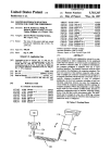
FIG. 1 is a high—level block diagram of a communication
system which allows voice signals and data to be commu
nicated between two stations:
program or a combination of each. The multi-player aspect
of the game is handled by having each game console accept
inputs directly from its local player and accept inputs
remotely for the other players. For e?iciency. the remote
data and which needs to be transmitted with low delay.
One advantage to the present invention is full use of the
available bandwidth through the use of data framing without
45
data is often summarized and/or compressed so that the
remote data can be timely transmitted over telephone lines.
FIG. 2 is a more detailed block diagram of one station in
the communication system of FIG. 1;
FIG. 3 is a chart showing examples of the data transmit
table over the D+V communications system and the proto
cols used at several network levels for these types of data;
FIG. 4 is a schematic diagram of an HDLC (High-level
Data Link Control) frame. as used with the present inven
For example. while local input might include each key press
or input device movement of the local player. the remote
data sent out from the local game is often limited to control
information which affects the play of the game from the
tion;
perspective of the remote players.
FIG. 5 is a schematic diagram of a modi?ed HDLC frame
used to transmit video game control data or other low
not to confuse the remote players. For example. if the game 55 delay-tolerant data and voice data at the same time; and
character of the local player moves. the remote game con
FIG. 6 is a schematic diagram of a PlayLinkTM frame used
sole needs to be noti?ed of the movement quickly so that the
for variable-length low delay data transmission over voice
remote player is not reacting to the old location of the local
data.
game character.
FIG. 7 is a state diagram of a process for sending voice
One prior art method of transmitting game data over
and game data over a single telephone line.
telephone lines is to transmit data packets between a local
FIG. 8 is a block diagram of a speci?c embodiment of the
This remote data needs to be communicated quickly. so as
modem and a remote modem using the v.42 packet transfer
present invention.
protocol. Typically. the minimum delay between a game
action being taken at a remote game console and that action
being communicated to the local game console is 28 to 150
milliseconds. For some game information. this is acceptable.
But for fast action scenes. such as where the game characters
65
DESCRIPTION OF THE PREFERRED
EMBODIMENTS
FIG. 1 shows a communication system 10 according to
the present invention. Communication system 10 allows for
5.757, 890
3
4
the transfer of data from one site 12 to another site 12a
numbered ISO-3309. “Data Communication-High-Level
Data Link Control Procedure—-Frame Structure”.
Voice CODEC 50 is coupled to handset 26 via twisted pair
30. and is also coupled to HDLC controller 52 to provide
digitized compressed voice data to HDLC controller 52. A
data port of HDLC controller 52 is coupled to subsystem 22
(see FIG. 2) to receive data from computer system 20. This
through a public switched telephone line 16. Site 12. which
is essentially similar to site 12a. is shown with a computer
system 20. a data communication subsystem 22. a D+V
(data+voice) modem 24 and a telephone handset 26. D+V
modem 24 is coupled to subsystem 22 via a communications
cable 28. and to handset 26 via a twisted pair 30. D+V
modem 24 is also connected to line 16. Station 12a includes
a computer system 200. a data communications subsystem
coupling. in one embodiment. is a standard RS-232
connection. while in another embodiment. it is a parallel
data bus. HDLC controller 52 is also shown coupled to
22a. a D+V modem 24a. and a handset 26a.
image CODEC 40 and MIDI instrument 42 using those
devices’ standard interfaces. In a video game application.
It should be apparent that other variations are possible.
For example. D+V modem 24 can be integral to subsystem
22 and/or system 20. as would be the case if system 20 is a
lap-top computer and D+V modem 24 is an internal
telephone/modem. Also. handset 26 need not be as depicted.
but could be a headset or other microphone and/or earphone
combination. For high performance game systems. a hands
free headset with earphones for stereo game sound com
bined with the remote player’s voice and an attached micro
phone is typically used. For other applications. handset 26 is
interchangeable with other devices which communicate
real-time data. If D+V modem 24 is internal to subsystem
22. then cable 28 might be replaced by an internal bus with
voice might be obtained from a headset/microphone or a
speakerphone.
HDLC controller 52 frames each of the data streams input
thereto into frames. while multiplexing the frames at its
output to modern module 54. HDLC controller 52 also
de-packetizes received frames and directs them to the proper
outputs. Because frames are only sent when data is presented
to HDLC controller 52. the channel bandwidth provided by
line 16 is used e?iciently.
When a call waiting signal is received at a local site 12.
for example. D+V modem 24 switches to an analog or digital
voice-only mode. Typically. a call waiting signal is seen as
similar functionality.
In operation. computer system 20 transfers data between
itself and system 20a over line 16. while voice communi
cation occurs between handset 26 and handset 260. all using
only line 16. In many applications. computer systems 20.
20a and subsystems 22. 22a cannot be easily modi?ed. With
the D+V modem. such systems do not need to be modi?ed.
because the interface over cable 28 is transparent to voice
30
traffic. This is possible since most modern communications
subsystems are con?gured for handshalcing with a modem
which allows a modem to slow down the passage of data
from the communications subsystem to the modern when the
modem has di?iculty keeping up. The effect of voice trans
a disturbance on the line. When D+V modem 24 detects the
disturbance. it switches to a voice-only mode. D+V modern
240 at the remote site should also detect the disturbance and
go into voice-only mode. At that point. the players can
communicate by voice and the local player can proceed in a
conventional manner to handle the waiting call. i.e.. inform
the remote player that the local player will be taking the call.
“?ash” the hook to switch to the waiting call. and then return
to the ?rst call when ?nished with the waiting call.
While the call waiting is being handled in voice-only
35
mode. the modem modules 54 at the local and remote sites
are not transmitting. To allow each player to control their
D+V modem. a pop-up program is provided at computer
system 20 and computer system 20a. Where the computer
systems 20. 20a are DOS-based personal computers. the
mission on data transmission at cable 28 is only to create an
apparent slowdown in the D+V modem’s data transmission
rate. and only when voice data is being transferred. Of
course. in some embodiments. D+V modem 24 accepts
con?guration commands over cable 28 which are not found
pop-up program is a terrninate-and-stay resident (TSR)
program The TSR gives a player the opn'on to pause the
game or hang up the line and gives the local player the
option to ?ash the hook to take the waiting call. If both
players choose to pause the game. they can pick up the game
in a standard data communications interface.
As shown in FIG. 1. D+V modem 24 also accepts other
data sources. which carry either non-real-time data 32 or 45 where it left off.
Once the local player is ?nished with the waiting call. he
real-time data 34. Each of these sources of data is multi
plexed onto line 16 as explained below in connection with
FIG. 3.
FIG. 2 is a more detailed block diagram of one site. 12.
of communication system 10. Site 12 is shown with D+V
modem 24 in greater detail. an image CODEC (analog
50
or she can signal. via the TSR. that the waiting call should
be dropped and D+V modem 24 should ?ash the hook to
return to the original call. Then both players signal. via the
TSR. that the two D+V modems should go into D+V mode
and resync the modems. Since the TSR pauses the game. the
game can continue where it left off. The TSR can also
include the capability to pause a game. have the phone line
and destination of non-real-time data. and a MIDI instru
dropped entirely. and then pick up where it left off by
ment 42 as a typical source and destination of real-time data.
D+V modem 24 is shown including a voice CODEC 50 55 redialing to re-establish the connection. resync the modems
and then unpanse the game.
which codes/decodes voice signals including compression/
coder/decoder) 40 and a CCD camera 41 as a typical source
The analog call waiting bypass and digital call waiting
decompression. an HDLC (?igh-Level Data Link
Qontrol) ?ramer/deframer 52 (HDLC controller. for short).
bypass are illustrated in FIG. 2. Each call waiting bypass is
a voice-only mode. since modern module 54 is bypassed. In
which communicates with a modem module 54 using HDLC
frames such as frame 56. and an analog front end (AFE) 58.
which is coupled to modern module 54. An output of AFB
58 is coupled to a data access arrangement (DAA) 60. which
is in turn coupled to line 16. Frame storage 62 is also
provided for buffering frames Where data is framed faster
than the capacity of telephone line 16.
Except where noted otherwise. HDLC controller 52 oper
ates per the HDLC protocol as de?ned in the ISO document
the case of a digital bypass. AFE 58 reroutes all incoming
data directly to voice CODEC 50 and the data is interpreted
as voice data. In the case of an analog bypass. relays 64 and
66 switch the telephone line 16 directly to twisted pair 30.
In either case. the voice communications have the use of the
65
entire bandwidth of the telephone line.
If the local player chose to permanently switch to the
waiting call. the local D+V modem drops the current
5,757,890
6
5
(original) call and switches to the waiting call as described
above. Once the call is over, the local modem hangs up the
line altogether. This latter option is typically not needed for
point-to-point connections. but is used in cases where the
remote modem is part of a modem pool and the remote
modem or computer system is programmed to drop a line
after a set period of inactivity. In some embodiments. the
TSR or pop-up will stay active (on-screen) for the duration
of the waiting call and then give the user an opportunity to
re-establish the connection to the remote D+V modem
TABLE 2-continued
Data Stream Type
38
Text
36
The Control ?eld contains one or two bytes. per the V.42
check sum on the address. control and data ?elds.
Since each HDLC ?ame contains an address indicating its
data stream type. and each ?ame contains only data from
This is very useful if the user wants to restart a game with
the same state as when the game was interrupted by the call
one type of data stream. HDLC controller 52 can easily
waiting signal.
types. an exemplary application is shown. although other
applications are possible. As indicated. all the various data
types use the HDLC protocol at the link network layer (of
the standardized seven layer network model).
As FIG. 3 illustrates, di?’erent error correcting schemes
Graphics
speci?cation. The FCS ?eld is calculated by performing a
before handing control back to the communicating process.
FIG. 3 is a chart showing several sources of data which
are transferrable over a telephone line. For each of the data
Address
15
separate received frames for each data stream multiplexed
onto line 16. And since ?ames for the various data types can
be freely intermixed. the ‘full bandwidth of the channel is
20
dynamically allocated to the various data streams.
If data ?om all data streams is presented to HDLC
controller 52 faster than the channel can carry the data. some
of the data is framed and bufferred into frame storage 62.
Alternately, where provided. HDLC controller 52 will send
are used for real-time data and non-real-time data. Real-time
data may be error-corrected using forward error correction
control signals back to the source of a non-real-time data
(FEC). while non-real-time data may be corrected using the
stream to indicate that modem 24 is temporarily busy (e.g..
sending an XOFF byte or a CI‘S o?’ signal back to subsystem
V.42 standard’s protocols. wherein a block received in error
22 over an RS-232 line which uses software handshaking to
results in the receiving modem requesting re-transmission.
hold up data at the sending end). When real-time data anives
fast enough to occupy the entire channel. the non-real-time
Although voice may use FEC. some voice ?ames might
have too many errors and thus be unrecoverable. If the error
is not recoverable, then the receiving modem replaces the '
data streams are held up or bu?’erred. so that the real-time
data arrives at the remote site in real time.
The D+V modem at the remote site can be configured to
signal which would have resulted ?om the frame with
silence or the previous voice ?ame to avoid crackling and
pops due to noise. The V.42 standard is de?ned in CClTI‘
Recommendation V.42. “Error Correcting Procedures for
DCEs Using Asynchronous to Synchronous Conversion”.
ignore any unrecoverable packets which contain voice data
and replace the voice data with voice data which would
translate to silence or average the erred gap. This way. a
35
occur if mors in the voice ?ames were present in the voice
FIG. 4 is a schematic diagram of an HDLC frame. as used
signal presented to the listener.
with the present invention. An HDLC ?ame comprises the
?elds shown in Table l. The addresses that may be assigned
Remote video game data is real-time data which presents
particular problems. as remote video game data is extremely
in a typical implementation for several data stream types are
shown in Table 2. below. As should be apparent. other
assignments of values for data stream addresses are possible
so long as the sender and the receiver of a data stream agree
on the meaning of the addresses.
TABLE 1
listener is not subjected to noises and pops which might
time-sensitive and once presented to a local modem such as
modem 24 shown in FIG. 1. it must be quickly transported
to the remote modem 240 and to the remote game system
200. Fortunately. the bandwidth required for this data is
relatively low. Game communication generally falls into one
45
of two types: 1) input update and 2) state update. In an input
update system. a remote machine sends a local machine data
indicating the inputs (keyboard. joystick. mouse. etc.) the
Fields of an HDLC ?ame.
Field
remote machine received and both the remote and local
Contents
game machines calculate what the effect of those inputs is.
be it character movement. scoring. option selection. or the
Start Flag 01111110
Arkiress
Identi?es the data stream type (see Table 2).
Control
The V.42 speci?cation speci?es the use of this
?eld for data. For voice, this ?eld is optional.
Data
A portion of the data stream which has been ?amed
FCS
Frame Check Sum (calculated per the HDLC standard)
End Flag
01111110 (Could be combined with Start Flag of
next frame)
like. In a state update system. the remote machine acts on the
inputs to change the state of the game and the remote
machine communicates the new state of the game. The
55
state update' is used for real time games such as chess.
FIG. 5 is a schematic diagram of a modi?ed HDLC frame
used to transmit video game control data or other low delay
data. The video game control data packets are of a pre
agreed size. such as N bytes. where each modern agrees on
the value of N. so that no bandwidth need be used to signal
TABLE 2
Data Stream Type
Address
Voice
Video
Sound
32
31
35
Image
33
Data Blocks
Control
37
34
advantage to an input update system is that very little data
need be communicated in a given time period. but the
advantage of state update systems is that each computer
need only perform the input calculation for its local inputs.
Typically. input update is used for fast action games and
65
the end of a video game control data packet. If regular
HDLC ?ames were used. either the remote video game data
would need to be accumulated into a frame. which causes an
5.757.890
7
8
unacceptable delay. or each N-byte packet would be trans
describes the states of a state machine implemented in a
D+V modem such as Dt-V modem 24.
mitted as a separate packet. which would also cause a delay.
since the transmission of the data must wait at least until any
In the ?rst state (S1). the D+V modem is waiting for game
packet transmission in progress when the video game data is
presented to the modem has completed. The use of an entire
frame for each N-byte packet is also very wasteful of
data. If game data is sent to the D+V modem before a
bandwidth for low values of N. such as N=4 or N=5. since
escape code. The escape code is known as an “Abort Flag".
transitions to state S3. where the D+V modem checks for the
presence of voice data. If no voice data is present. the state
machine returns to state S1. but if voice data is present. the
state machine transitions to state S4. Once a game packet has
been sent at state S2. the state machine also transitions to
state S4.
In state S4. the D+V modem pauses the game data source
so no game data is lost. If the game data source is a game
and is inserted in between the voice packet being transmitted
by the local modem when the video game data is received by
which expects to send data via a UART (universal asyn
chronous receiver-transmitter) port. which the D+V modern
the local modem. That way. the remote video game data
need not be delayed until the end of the frame. The Address
and Control ?elds are not needed in this application. since all
frames are addresses as voice packets. The FCS ?ag is
eliminated. because otherwise the insertion of the N-byte
implements or emulates. then to pause the source the D+V
modem simple sends a signal to indicate that the UARI‘ is
waiting period is over. the state machine transitions to state
S2 and a game data packet is sent. If not. the state machine
the other ?elds of the frame might be larger than the data
?eld.
As shown in FIG. 5. the modi?ed HDLC frame contains
the same ?elds as an HDLC frame. except that the Address.
Control. and FCS fields are optionally removed. The N-byte
packet is simply placed between voice packets with an
busy sending a signal. This is especially useful for games
20
data packet would cause a check sum error. The elimination
of these various ?elds leads to more e?icient use of band
width.
which were not written to take into account the possibility of
having a voice and data modem. The state machine then
transitions to state S5. Where the D+V modem sends voice
packets over the line until silence is encountered
While in state S5. if game data is received. the state
The insertion of the N-byte packet is detectable at the
machine transitions to state S6. where the game data is
remote modem. since the Abort Flag is not a bit sequence
inserted into a voice packet using the escape sequence (abort
which would occur within a voice packet. In one
?ag) as shown in FIG. 6 and the state machine returns to
embodiment, the Abort Flag is the bit sequence “1111111.”
The end of the frame is still detectable because the End Flag
state S5. If silence is encountered. the state machine returns
to state 81. The game data is typically sent sixty times per
second. to match the screen refresh rate. If four bytes of
game data were send each time. the channel width between
is also a bit sequence which would not occur in a voice
packet. Ifthe value of N is ?xed ahead of time. then the bytes
in the N-byte packet can take on any possible bit sequence
without ambiguity.
Where regularly spaced. ?xed length packet transmissions
the two machines would be 1920 bits/second (4 bytes/
period><60 periodslsecond><8 bits/byte).
remote D+V modern and the local D+V modem perform a
FIG. 8 is a block diagram of one speci?c embodiment of
a modem card 100 according to the present invention.
Modem card 100 is shown combined with a headset 102. an
analog mixer 104. a game computer 108. a DAA 110. which
is in turn coupled to a telephone line 112. If game computer
handshake after which it is agreed that all packets will be
108 is a general-purpose personal computer. modem card
are not suitable or appropriate for a pre-con?gured game. the
35
PlayLinlrTM framing protocol can be used. An example of a
PlayLinkl'M frame is shown in FIG. 6. In this protocol. the
voice packets and that voice data and game data will not
contain the bit sequences associated with the Abort Flag.
Voice data is then sent delimited by frame ?ags and game
data is sent by interrupting a voice frame. inserting an Abort
Flag in the transmitting data stream. followed by game data
and a second Abort Flag. If any voice data remains for the
current frame. it is transmitted followed by the next frame
?ag. With this protocol. data delay can be as low as 17 msec.
In a ?rst mode of operation described above with refer
ence to FIG. 4. voice packets have priority and are sent if
present and data is sent if no voice is present. The maximum
size of a packet is 20-30 bytes and the modern checks for
100 could be a card designed to be inserted into the personal
computer's add-on card slots.
Headset 102 provides a game player with the game’s
45
remote player’s D+V modem. Analog mixer 104 combines
the voice from modem card 100 and the game sound from
game computer 108. Analog mixer 104 might be included on
modem card 100 or might be included as part of a sound card
used with game computer 108.
Modern card 100 is shown comprising a coder-decoder
(CODEC) 120 for converting digital compressed voice data
into an analog voice signal. a digital signal processing (DSP)
pending voice data between each packet.
In a second mode of operation. voice packets are sent until
data is pending. Typically, the modem sends voice until at
least 1 to 10 bytes of data are pending. Once data is ready
to be sent. the data is inserted in the voice packet being sent
at the time. In one variation. the data is sent in ?xed length
sound as well as the remote player’s voice and headset 102
also receives the local player’s voice for transmission to the
55
chip 122 which acts at the processor to control modem card
100 and perform the necessary computations. an AFE 12A to
translate the digital signals coming from DSP chip 122 to
analog signals suitable for transmission over telephone line
112 and to digitize incoming analog signals to digital signals
sub-packets preceded by an abort ?ag.
which are provided to DSP chip 122. DSP chip 122 has
FIG. 7 is a state diagram of a third mode of operation for
sending voice and game data over a single telephone line.
One problem with using a single line is that both voice and
game data have a high priority. Voice data has a high priority
interfaces to CODEC 120 and game computer 108. as well
as to a ROM (readonly memory) 126. an SRAM (static
random access memory) 128 and an EEPROM (electrically
erasable programmable ROM) 130. ROM 126 and
EEPROM 130 together contain the instructions which tell
so that the voice data is not received with annoying gaps at
the other end. Game data is high priority so that even fast 65 DSP chip 122 how to combine the voice signal from
CODEC 120 and the game data from game computer 108
action games can be played with the local and remote
and send it out as well as telling DSP chip 122 how to
machine being substantially in sync. This state diagram
5,757,890
9
10
separate incoming game data from voice packets and con
vert the voice packets into a voice signal. The bulk of the
purpose program running in the background with which
modem card 100 can communicate. When one player (using
the local players as an example) gets call a call waiting
signal. the local DSP chip detects the signal and sends a
message to the special purpose signaling program. which
program is found in EEPROM 130. which in one particular
implementation is a 128K by 8 EEPROM. This allows the
program used by DSP chip 122 to be updated over telephone
line 112 by downloading new versions of the DSP software.
ROM 126 need only contain the routines for handling the
interrupts the game with a message to the screen that a call
is waiting. The signaling program gives the local player the
option of what to do about the waiting call. If the local player
chooses to ignore the waiting call. the local DSP chip does
downloading process. SRAM 128. in the particular
implementation. comprises three 3K by 8 RAM chips.
nothing and the signaling program returns to the back
Variations of modem card 100 are possible to take advan
ground. If the local player chooses to take the waiting call.
the local player will inform the remote player that the remote
tage of the environment of modem card 100. For example.
where most of the functions of modem card are implemented
player should indicate to the remote computer 200 that the
game should be temporarily paused. Once the waiting call is
complete. the local player tells to the remote player that
on an application-speci?c integrated circuit (ASIC). analog
mixer 104 and CODEC 120 might be combined into a
mixer/CODEC on a chip. Another environmental advantage
is where the modem card 100 will be used with a personal
game play should resume. and each player signals their
respective TSR or pop-up that the data link should resume.
The above description is illustrative and not restrictive.
Many variations of the invention will become apparent to
20 those of skill in the art upon review of this disclosure. The
by the personal computer.
scope of the invention should. therefore. be determined not
A detailed description of this particular implementation is
computer of a known design and capacity. In such cases.
ROM 126 and SRAM 128 need not actually be present on
modem card 100. Instead. their functionality can be handled
set forth in the accompanying Appendix.
The operation of modem card 100 typically begins with a
game player (referred to here as the “local” player) powering
up the local game computer 108. putting on headset 102 and
25
dialing the telephone number of the remote player. Dialing
with reference to the above description. but instead should
be detmmined with reference to the appended claims along
with their full scope of equivalents.
The attached Appendix A is a Design Reference Docu
ment entitled “Phylon PHY2000 PC Adapter Card Refer
can be provided by either game computer 108 or an interface
ence Design” which describes a speci?c embodiment of a
to DSP chip 122. The remote player will usually respond by
answering the telephone manually. At this point. no game
modem programmed to perform dynamic voice and data (or
other non-real-time and real-time data streams) multiplexing
data is being transferred and modem card 100 is operating
essentially as a conventional telephone. using headset 102 in
30
Appendix B is “Phylon PlayLink Talk ‘n’ Play Interactive
place of the conventional handset.
If the remote player is agreeable. the remote player
powers up the remote game computer and remote headset.
Each player then initiates a handshake process in which both
the local modem card and the remote modem card con?rm
that they both have the D+V capability. If the handshake is
successful. the modem cards indicate to their respective
game computers that transmission of game data is possible.
Game computer 108 could be configured to handle call
waiting. One way to implement this is to have a special
over telephone lines sold as a PC-compatible add-in card.
Games.”
Appendix C is a Technical Data Manual for the PHY1412
35
Safari Chip-Set for Remote Gaming.
Appendix D is a Hardware 8: Software Installation
Manual for PHY2000 PC.
Appendix E is a “Phylon PHY2000 MessageLink Soft
ware User’s Manual.”
Appendix F is a “Phylon PHY2000 PC PhyLink Software
User’s Manual.”
5 ,757,890
X PHYLQN
PHY2000
PC Adapter Card
Reference Design
5,757,890
15
16
PHY2000
PC Adapter Card Reference Design
Phylon's PHYZOOO PC Adapter Card is a high performance simultaneous voice and data. and high speed fax and
data internal modem‘ The adapter card utilizes Phylon‘s PHYZOOO communications chip-set which consists of two
CMOS VLSI chips: the high performance PHYll8 DSP and the PHY2l2 analog front-end (AFE). This solution
provides very high level integration and leads to a cost-effective. reliable and highly manufacturable product,
The PHYZOOO features a true SoftComTM architecture optimized for the PC environment, Communications
DSP code is booted from system disk to the PHYZOOO for execution upon system power-up, Modem configuration,
function. and operation can be changed dynamically. This permits the PHYZOOO to instantly respond to
any application programs performance demands. Easy installation and setup is insured because the COM port and
IRQ are automatically selected: the selections can also be modi?ed in software.
The PHYZOOU Supports BizLink. digital simultaneous voice and data (DSVD) operation on a single telephone line
for collaborative computing applications. DSVD operation is enhanced with adaptive channel bandwidth allocation which
optimizes voice and data rates and permits full modem speed for data during voice silences.
The PHYZOOO also supports PlayLinkT“. an implementation of DSVD optimized to realize maximum real-time
performance in interactive remote gaming applications. When executed. PLAYLINK.EXE‘s user-friendly graphical
user interface (GUI) operation also greatly reduces and simpli?es modem setup, dial-up and connection, and game
initialization procedures.
This book dicusses and illustrates a complete PC adapter card modem reference design based on the
PH V2000 clilp-set The design is offered as an example for on which to base subsequent proprietary designs. or to utilize
it as is after completion of appropriate agreements and acknowledgments.
FEATURES
PlayLinlt Talk ‘N’ Play Interactive Games
_
,
. .
p
.
l
Modem Features/Capabimi"
'
'
Cf’mPa“b""Y “ "h a" “5M5 nmdem games
'
Simultaneous mice and real-time game data
' Game s>nchronizauon
- Ver)v lo“ data delay (I? ms)
DSVD for collaborative computing (to be soft
ware upgraded to v.62 upon approval of standards)
I
\
‘
'
lTU-T V34. V.32bis. V33. V23. V,22bis, V21
V.2l. Bell 2l2 and I03 at data rates of 28800
. Supports Ca“ wailing during game play
26400. 24000. 2l600, l9200. 16800. I900, lZ’OOOi
,
9600. 7200. 4800. 2400. 1300 and 300 biLs
Fmmdh DOS and Wmdowvbascd GUIS
'
BizLink Collaborative Computing
'
Compatible with whiteboard shared Windows
'
Apphcali‘?“
Call Waiting support
'
Friendly Windows-based GUI
Telephony
.
‘
Full-duplex speakerphone‘ Dialer OUls
' AI'ISWEI'll’lg macliinc recording and playback with
'
Group 3 FAX. V17 V 29 V271" and v 2] Chan_
nel 2 with V.2l carrier detection concurrent with
high-speed
l
image data reception
' Modem AT Commands
'
'
VAZ/VAZbis drivers
' Software upgradeable
Fax Class I AT Commands
_
inlelggg?'e‘ UART with ‘K by“: ‘meme. buffers m
concurrent DTMF detection
| Mbius transfer me and 3 Seconds “buffering
Faxlvolcc Mail switching
under Windows”
5,757,890
17
3g PHYLQN
18
PHY200
C Adapter Card
Introduction
Included herein are descriptions of the PHYZOOD PC Adapter Card hardware features — schematics, pcb
layout, bill of materials, and supporting software features including a list of supported AT commands.
You may, with completion of appropriate agreements and acknowledgments;
(I) use the Phylon design as a model/example on which to base your own proprietary modern design.
(2) modify the Phylon design to meet your own unique requirements, or
(3) after appropriate quali?cation utilize the Phylon design as is.
Phylon can provide the associated schematic and library ?les on diskette in OrCAD Release IV (16-bit) or
OrCAD SDTBBB, version 1.21 (32-bit) formats. They may also be downloaded in compressed format
(PHYQOOOZIP) from the Phylon BBS; that phone number is (510) 656-0916. They may also be obtained
from Phylon's Internet website (http://wwwphyloncoml).
PCB layout ?les (gerber ?les. netlist, etc.) as well as supporting software will be provided under license or
appropriate agreements.
5,757, 890
19
20
3% PHYLQJN
PHY2£
Hardware Design
@ms wuun. wc, PHHUW PC u
BLlAHd
NKHMM“ :
PC Adapter Card
5,757,890
21
22
3% PHYLQN
22
PHY200\
c Adapter Card
Block Diagram and Interface Signals
A funcnonal diagram and the related interface signals are shown in Figure l. S1gnal descnption
and charactenstlcs are summarized in adjacent tables‘
00-015
‘
MIC I"
Headphone
Interface
A0 - A9
AEN
MIXER
¢
~
\
_
-12v v‘
10R
Headphone
'
;
‘0W
Micrc»
phune
'
Interface
stem
'
,
,
Sound
‘IOCHRDY our
Cam
10CS16
SPEAKER
[Rm
ISA
Bus
Head
Phone
Aud'o
‘
Speaker
0204
DSP 1m
(max ‘- PF7)
*
PHY2000
m.
‘1
ATX
‘5v Ncc)
~
AR+
Phone
(3ND
12V
’—>
f
‘
‘12v
—->
Ph
"-
L'ne
Line
1
AR‘
OHRC
‘ one
Interface
_
Rm
Osc?loscope
EYEX
_;
Power
Regulator
-5v (Vnm)
EYEY
‘
Cur
'
‘ "l
Disptay
interface
Figure 1. PHY2000 PC Adapter Card Functional Block Diagram and Interface Signals
5 ,757,890
23
24
X PHYLQN
‘*3
PHY;
0 PC Adapter Card
PHYZOOO Interface Signals
NAME
TYPE
DIS-D0
Bldir.
DESCRlPTlON
16'b1t Data Bus
NAME
TYPE
AGND
Ground
GN'D
Ground
Digital Ground
+5V
~12V
+12V
Power
Power
Power
+5V Supply
-12V Supply to Mixer Circuit
+12V Supply to Mixer Circuit
MIC IN
MIXER
Input
Output
Microphone lnput
Voice ()utput 10 Mix"
IO-bat ISA Address Bus
DESCRIPTlON
Analog Ground
AQ-AO
Output
AEN
Input
Address Enable
IOR\
IOW\
Input
Input
Read Enable
Wnte Enable
[OCS16\
Output
l?-lnt U0 Chip Select
SPEAKER
Output
Audio Output
IOCHRDY
Output
1/0 Channel Ready
IRQ3
IRQ4
Output
Output
COM Port Interrupts
ATX+.ATXAR+. AROHRC
RD\
Output
Input
Output
Input
Transmitter Analog Output
Recezver Analog Input
Off-Hook Relay Control
Ring Detect
IRQx
Output
DSP Interrupt w ISA Bus
EYEX
Output
Constellauon Output - X Axis
(PI-‘7 +1RQX. x=7,10.1l.l2. or 15)
EYEY
Output
Constellatmn Output _ Y Ant
PHYZOOD Recommended Operatlng Conditions
Symbol
Parameter
VIm
Supply Voltage
Tm“
Amlnent Operating Temperature
Min
Max
Unit
4.50
5.50
V
0
+70
‘C
5,757,890
25
24
PHY2000
Adapter Card
PHYZODO Reference Design PC Adapter Card Schematics
The PHY2000 pinout diagram is shown in Figure 2‘ Reference design PC adapter card schematics are
shown in Figures 3 through 7‘ A recommended Bill of Matenals follows the associated schematics‘
V I 1 I i I Y
1
1 I‘
1
0 009999
2
kkklilil?k élélilililili lililililéléiélél
4
1
1716
-zQgi
U
T“InTEHT
7
in
]2
7
Figure 2. PHY2000 Pinout Diagrams