1
OWNER'S
MANUAL
MODEL NO.
917.299751
CRRFrZMR#®
Caution:
Read and follow
all Safety Rules
and Instructmns
Before Operating
This Eqmpment
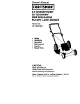
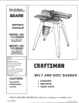
5.0 HP
14 INCH
DTH
REAR TINE TILLER W_TH
COUNTER ROTATING TINES
• Assembly
• Operation
° Customer Responsibilities
• Service and Adjustment
° Repair Parts
Sears, Roebuck and Co., Chicago, IL 60684 U.S.A.
SAFETY RULES
Safe Operation
Practices for Walk-Behind
Powered Rotary Tillers
TRAINING
• Read the operating and service instructionmanuai carefully. Be thoroughly familiar with the controls and the
proper use of the equipment, Know howto stop the unit
anddisengage the controls quickly.
• Never allow children to operate the equipmenL Never
allow adults to operate the equipment without proper
instruction.
, Stop the engine (motor) when leaving the operating
position.
• Take all possibleprecautionswhen leaving the machine
unattended_ Disengage the power take-off, lower the
attachment, shift into neutral, stop the engine, and
remove the key.
• Before cleaning, repairing, or inspecting, shut off the
engine and make certain all movingparts have stopped.
Disconnectthe spark plug wire, and keep the wire away
from the plug to prevent accidental starting.Disconnect
the cordon electricmotors_
, Keep the area of operation clear of all persons,particularly small children, and pets.
PREPARATION
, Thoroughly inspect theareawhere the equipment is to be
used and remove all foreign objects.
• Do not runthe engine indoors; exhaust fumes are dangerous.
• Nevel"operate the tillerwithout proper guards, plates,or
other safety protective devices in place.
. Disengage all clutches and shift into neutral before
startingthe engine (motor).
. Do not operate the equipment withoutwearing adequate
outer garments. Wear footwear that will improvefooting
on slipperysurfaces.
• Handle fuel with care; it is highlyflammable.
•
•
•
• Keep children and pets away
• Do not overload the machine capacity by attempting to tiU
too deep at too fast a rate
• Never operate the machine at high speeds on slippery
surfaces Look behind and use care when backing,
• Never allow bystanders near the unit
Use an approved fuel container°
Never add fuel to a runningengine or hot engine.
Fill fuel tank outdoors with extreme care, Never fill
fue! tank indoors.
• Use only attachments and accessories approved by the
manufacturer of the tiller (such as wheel weights,
counterweights, cabs, and the like)
• Never operate the tiller without good visibility or light,
•
Replace gasolinecap securely and clean up spilled
fuel before restarting.
• Use extensioncords and receptaclesas specified by the
manufacturer for all units with electric drive motors or
electric starting motors.
• Be careful when tilling in hard ground The tines may
catch inthe ground and propel the tiller forward If this
occurs, let go of the handlebars and do not restrain the
machine
• Never'attemptto make any adjustments whilethe engine
(motor) is running (except where specifically recommended by manufacturer).
OPERATION
MAINTENANCE AND STORAGE
, Keep machine, attachments, and accessories in safe
working condition,
• Do not put hands or feet near or under rotating parts,
• Check shear bolts, engine mounting bolts, and other
bolts at frequent intervals for proper tightness to be sure
the equipment is in safe working condition,
• Never store the machine with fuel in the fuel tank inside
a building where ignition sources are present, such as hot
water and space heaters, clothes dryers, and the like
Allow the engine to cool before storing in any enclosure
• Always refer to the operator's guide instructions for
important details if the tiller is to be stored for an extended
period
• Exercise extreme cautionwhen operatingon or crossing
gravel drives, walks, or roads. Stay alert for hidden
hazards or traffic. Do not carry passengers_
• After strikinga foreign object, stop the engine (motor),
remove the wire from the spark plug, thoroughlyinspect
the tiller for any damage, and repair the damage before
restartingand operating the tiller.
• Exercise caution to avoid slippingor falling.
• If the unit should start to vibrate abnormally, stop the
engine (motor) and check immediately for the cause.
Vibrationis generally a warning of trouble_
-IMPORTANT
-
Cautions, tmportants, and Notes are a means of attracting attention to important or critical information in this manual
I&
point out Important safety precautlons. It means -- Attention! Become
CAUTIONI Look for this symbol to
Aiertl Your safety is Involved.
.....
ii ..............
IMPORTANT=
USED TO ALERT YOU THAT THERE
IS A POSSIBILITY OF DAMAGING THIS EQUIPMENT.
|
i
I
I
1
NOTE: Gives essential information that will aid you to
better understand, incorporate, or execute a particular
set of instructions
2
CONGRATULATIONS
onyourpurchase
ofaSearsTiIler,.
It hasbeendesigned,
engineered
andmanufactured
to
giveyouthebestpossible
dependability
andperformance.
Shouldyouexperience
anyproblems
youcannoteasily
remedy,pleasecontactyour nearestauthorized
Sears
ServiceCenter/Departmento
Theyhavecompetent,
welltrainedtechnicians
andthepropertools to service or repair
PRODUCT SPECIFICATIONS
HORSEPOWER:
5.0 HP
DISPLACEMENT:
12o57 cur in.
this unit.
GASOLINE CAPACITY:
Please read and retain this manual The instructions will
enable you to assemble and maintain your tiller properly,.
Always observe the "SAFETY RULES".
3 QUARTS
(UNLEADED)
OIL (20 OZ CAPACITY):
SAE 30W
(SAE t0W 30)
SPARK PLUG (GAP °030 IN.):
Champion
RJ19LM
MODEL
NUMBER
917.299751
SERIAL
NUMBER
MAINTENANCE
DATE OF
PURCHASE
A Sears Maintenance Agreement isavailable on this producL Contact your nearest Sears store for details.
THE MODEL AND SERIAL NUMBERS WILL BE
FOUND ON THE MODEL PLATE ATTACHED TO
THE TOP OF THE TRANSMISSION°
CUSTOMER
•
Read and observe the safety rules.
•
YOU SHOULD RECORD BOTH SERIAL NUMBER
AND DATE OF PURCHASE AND KEEP tN A SAFE
PLACE FOR FUTURE REFERENCE.
.
Follow a regular schedule in maintaining, caring for and
using your tiller.
Follow the instructions
under the "Customer
Responsibilities" and "Storage" sections of this Owner's
Manual.
AGREEMENT
RESPONSIBILITIES
LIMITED ONE YEAR WARRANTY ON CRAFTSMAN
TILLER
For one year from date of purchase, when this Craftsman Tiller is maintained, lubricated, and tuned up according to
the operating and maintenance instructions in the owner's manual, Sears will repair free of charge any defect in
material or workmanship.
This Warranty does not cover:
•
Expendable items which become worn during normal use, such as tines, spark plugs, air cleaners and belts_
•
Repairs necessary because of operator abuse or negligence, including bent crankshafts and the failure to
maintain the equipment according to the instructionscontained in the owner's manual..
•
If this Craftsman Tiller is used for commercial or rental purposes, this Warranty applies for only 30 days from the
date of purchase.
WARRANTY SERVICE IS AVAILABLE BY RETURNING THE CRAFTSMAN TILLER TO THE NEAREST SEARS
SERVICE CENTER/DEPARTMENT IN THE UNITED STATES. THIS WARRANTY APPLIES ONLY WHILE THIS
PRODUCT IS IN USE IN THE UNITED STATES_
This Warranty gives you specific legal rights, and you may also have other rights which vary from state to state°
SEARS, ROEBUCK AND CO_, D/731CR-W SEARS TOWER, CHICAGO, 1L 60684
- IMPORTANT.
This unit is equipped with an internal combustion engine and should not be used on or near any unimproved forest-covered,
brush.covered or grass covered land unless the engine's exhaust system isequipped with a spark arrester meeting applicable
local or state laws (if any)° If a spark arrester is used, it should be maintainedin effective working order by the operaton
In the state of California the above is required by law (Section 4442 of the California Public Resources Code). Other states
may have similar lawso Federal taws apply on federal lands. See your Sears Authorized Service Center for spark arresten
Refer to the Repair Parts section of this manual for part number.
3
L
TABLE OF CON
.......
SAFETY
RULES
_,_
_.................
L±JUUlULU_
,,,I
,ll_
Inl,,
............................................................
_
....
II uln,,,, ..............................
MAINTENANCE SCHEDULE ...................................... 14
SERVICE & ADJUSTMENTS ................................. 16-19
STORAGE .................................................................... 20
TROUBLESHOOTING ................................................. 21
REPAIR PARTS-TILLER ........................................ 22-27
REPAIR PARTS-ENGINE ....................................... 28-31
2
CUSTOMER RESPONSIBILITIES ...................... 3,14-16
PRODUCT SPECIFICATIONS ....................................... 3
WARRANTY ................................................................... 3
ACCESSORIES ............................................................. 5
ASSEMBLY ................................................................ 6-8
OPERATION ............................................................. 9-13
INDEX
A
Adjustments:
Carburetor. .................................19
Depth Stake ............................. 10
Handle Height ............................t6
Side Shields..................................
11
Throttle ..................................... ! 9
Tines .......................................... 18
V-Belt (Ground Drive) .............. 17
Wheels ...................................13,16
Air Cleaner ............................................
15
B
Belt:
Belt Guard ....................................
t7
Repair Parts .................................
23
V-Bett (Ground Drive) ...............17
Engine (cont'd)
Lubrication ............................... 15
Oil Level ....................................... 11
Oil Type ...................................
11,15
Spark Plug .................................16
Starting ........................................12
Stopping .....................................10
Storage ..................................... 20
Winter Operation ..................... 15
F
Fuel:
Filling Tank .................................. 11
Storage ........................................20
Type .......................................... 11
Finish:
Maintenance ..............................16
C
H
Cooling System .................................15
Controls:
Choke ............................................9
Throttle ........................................ 9
Drive (Tines) ............................... 9
Cultivating ........................................ 13
Customer Responsibilities:
Air Cleaner .................................15
Cooling System ........................ 15
Finish........................................ 16
Maintenance Schedule ............ 14
Muffler ...................................... 16
Oil Change ................................ 15
Spark Piug ..................................16
Tines ...........................................18
Transmission ............................ 16
V-Belt (Ground Drive) .............. 17
Handle:
Height Adjustment ......................t6
Repair Parts .................................
22
D
Depth Stake:
Adjustment ............................... 10
Repair Parts............................. 26
E
Engine:
Air Cleaner ............................... 15
Cooling System ...........................
15
Fuel Type ....................................! 1
L
Lubrication:
Lubrication Chart .................... 14
Engine ........................................15
M
Muffler:
Maintenance ............................ i6
Spark Arrester ............................ 3
O
Oil:
Level ........................................... 11
Type ......................................11,15
Operation:
Cultivating ................................. 13
Fill Fuel Tank ............................ 11
Starting Engine .............................
12
Stopping Tines & Engine ...........10
Tilling ......................................... 10
Tilling Hints .............................. 12
Tine Operation .................................
10
Transporting Tiller ..................... tl
Winter Operation .......................15
4
R
Repair Parts ..................................22-3t
Rules for Safe Operation .............oo.,..,2
S
Sewice & Adjustments:
Carburetor ................................ 19
Handle Height .......................... 16
Side Shields .................................t 1
Throttle .........................................
19
Tines ......................................... 18
V.Belt (Ground Drive) .............. 17
Wheels ................................. 13,16
Service:
Repair Parts ......................... 22-31
Service Record ......................... 14
Shear Pins:
Operation ................................... 12
Repair Parts .............................. 27
Spark Plug:
Gap ....................................................
3
Maintenance ............................ 16
Storage:
Fuel System ............................. 20
Tiller ........................................... 20
Tilling ..........................................
10,12
Tines:
Arrangement/Replacement .......18
Operation .................................. 10
Repair Parts ...............................27
Shear Pins ................................. 12
Transmission:
Maintenance ............................. 16
Repair Parts ...............................25
Troubleshooting ............................. 21
Transporting .................................... 11
W
Warranty ................................................
3
Wheels:
Adjustments .............................. 13
Removal .....................................16
Repair Parts ...............................24
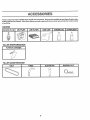
ACCESSORIES
These accessories were available when the tilter was purchased. They are also available at most Sears Retail outlets,
Catalog and Service Centers° Most Sears Stores can order repair parts for you when you provide the model number
of your tiller,
ENGINE
,,
SPARK PLUG
MUFFLER
GAS CAN
AIR FILTER
........ i,,i,
,!
i
,i,J............
:
:-.. -o
ENGINE OIL
STABILIZER
J)
..........
TILLER PERFORMANCE
iiiiiii1,,,,,,,11,11
FURROW
/,_,_
TILLER
"
i,,_
OPENER
r,,lllll .......
MAINTENANCE
BELT
TINES
CLEVIS PIN
5
HAIRPIN
CLIP
ill,
ii
.........
..................
ASSEMBLY
....................
TO ASSEMBLE
(1)
(1)
(1)
(1)
(1)
(1)
ill i,,
i ,m,L
, ,,,,i
ill
,,,,,,,i
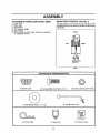
YOUR TILLER YOU WILL NEED:
OPERATOR'S
Utility knife
Wire cutter
Screwdriver
Tire pressure gauge
Pair of pliers
9/16" wrench (or 9/16" socket, ratchet, and extension;
or adjustable wrench)
POSITION
,,,l,,,,qw
(See Fig. 1)
The righthand (R.H.) and left hand (LH.) sides of yourtiller
are determinedfrom the operator's positionwhile standing
behindflier.
FRONT
LEFT
RIGHT
OPERATOR'S
POSITION
FIG. 1
i,,
illlllllll
-
,r
CONTENTS
i llll ill
ill
OF HARDWARE
-
• ill
PACK
/lllllll/
(2) Handle Locks
(2) Carriage Bolts 3/8-t6 UNC x I Gr. 5
(2) Center Locknuts 3/8-16 UNC
..............
@
...............
°
(1) Handle Lock Lever'
(1) Flat Washer 13f32 x 1 x 11 Ga.
Hi
i NJp,,
,,, ,,,,,i,,,,,,,,,
I
(2) Hairpin Clips
(1) Cable Clip
6
(1) Owner's Manual
.1 ....
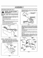
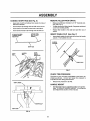
ASSEMBLY
(See Fig. 2)
staples when handling or disposing of
CAUTION:
Be careful of exposed
cartoning material.
Grasp handle assembly. Hold in "up" position, Be sure
handle lock remains in gearcase notch. Slide handle
assembly into position
i
f-
IMPORTANT: WHEN UNPACKING AND ASSEMBLING
TILLER, BE CAREFUL NOT TO STRETCH OR KINK
CABLES
•
Slowly ease handle assembly up and place on top of
carton,
o
Cut down right hand front and right hand rear corners
of carton, lay side carton wall down.
•
•
Remove packing material from handle assembly.
Separate shift rod from handle assembly.
HANDLE ASSEMBLY
"u.".OSITiON
While holding handle assembly, cut cable ties securing
handle assembly to top frame and depth stake. Let
handle assembly rest on tiller.
Remove top frame of carton.
•
..i
""
•
;_ _.. ,.
f
TIGHTEN HANDLE |
"'_"
I
CARTON
r
UNPACKING
i _
I LOOSEN HANDLE L_
i LOCK LEVER TO
LOCK LEVER TO
1
"_
I MOVE
FIG, 4
SHIFT ROD
Rotate handle assembly down to install two carriage
bolts and locknuts, Insert rear carriage bolt (Fig. 5) first,
with head of bolt on Loll, side of tiller° Lower the handle
assembly. Tighten bolts so handle moves with some
resistance,
Q
m
insert second handle lock (with teeth inward) in the slot
of the handle base°
Place fiat washer on threaded end of handle lock lever,
Insert handle lock lever through handle base and
gearcase,
m
HANDLE
ASSEMBLY
With handle assembly in lowest position, securely
tighten handle lock lever by rotating clockwise, LeavIng handle assembly in lowest position will make it
easier to remove tiller from carton,
HANDLE
LOCK
FIG. 2
INSTALL HANDLE (See Figs. 3, 4, and 5)
•
SLOT
Insert one handle lock (with teeth facing outward) in
gearcase notch. (Apply grease on smooth side of
handle lock to aid in keeping lock in place until handle
assembly is lowered into position.)
_
FLAT
WASHER
CARRIAGE
BOLT
HANDLE
LOCK
LEVER
HANDLE ASSEMBLY
/
_X,..7_oy
/
/
/!
HANDLE
LOCK
REAR
CARRIAGE
BOLT
LOCKNUTS
HANDLE
BASE
FIG. 5
FIG. 3
7
ASSEMBLY
CONNECT SHIFT ROD (See Fig. 6)
REMOVE TILLER FROM CRATE
•
Insert end of shift rod farthest from bend into hole of
shift lever indicator,
•
Make sure shift lever indicator ts in "N" (neutral) position (See Fig, 6)
•
•
Insert hairpin clip through hole of shift rodto secure,
Insertother end of shift rod _ntohole in shift lever,
•
,
Insert second hairpin clip through hole of shift rod.
Tilt tiller forward by Iiftirlg handie_ Separate cardboard
cover from leveling shield.
Rotate tiller handle to the right and pull tiller out of
carton,
ATTACH THIS END
TO SHIFT LEVER
•
INSERT CABLE CLIP
AI"TACH THIS
END TO SHIFT
•
INDICATOR
........
(See Fig. 7)
Insert plasticcable clip intohole on the back of handle
column. Push cables into clip.
LEVER _,,1
.....................
SHIFT ROD
SHIFT
HAIRPIN
CLIP
SHIFT
LEVER
INDICh;TOR
CABLES
'CABLE CLIP
FIG. 7
CHECK
TIRE
PRESSURE
The tires on your unit were ovednflated at the factory for
shipping purposes, Correct and equal tire pressure is
importantfor best tilling performance.
•
Reduce tire pressure to 20 PSt.
HANDLE HEIGHT
.......
•
HAIRPIN CLIP
SHIFT ROD
FIG, 6
8
Hand!eheight may be adjusted to better suitoperator.
(See TO ADJUST HANDLE HEIGHT' in the Service
and Adjustments section of this manual).
i,J
i,,
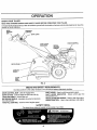
OPERATION
KNOW
YOUR
TILLER
READ THIS OWNER'S MANUAL AND SAFETY RULES BEFORE OPERATING YOUR TILLER,
Compare the illustrations with your tiller to familiarize yourself with the location of various controls and adjustments_ Save this
manual for future reference,
DRIVE
CONTROL
THROTTLE
CONTROL
SHIFT LEVER
BAR
SHIFT LEVER
INDICATOR
CHOKE CONTROL
RECOIL
STARTER
HANDLE
DEPTH STAKE
SHIELD
c
LEVELING
OUTER
SIDE
SHIELD
FIG. 8
MEETS ANSI SAFETY REQUIREMENTS
Our tillers conform to the safety standards of the American National Standards Institute°
DRIVE CONTROL BAR - Used to engage tines.
DEPTH STAKE - Controls depth at which tiller willdig,
LEVELING SHIELD - Levels tilled soil,
OUTER SIDE SHIELD - Adjustable to protectsmall plants
from being buried°
THROTTLE CONTROL - Used to control engine speed.
SHIFT LEVER - Used to shift transmission gears,
SHIFT LEVER INDICATOR - Shows which gear the
transmission is in.
RECOIL STARTER HANDLE - Used to start the engined
CHOKE CONTROL - Used when starting a cold engine,
SAFETY DECAL
The deca! shown below is located on the handle of your tiller,
OPERATION
The operation of any tiller can result In foreign oblects thrown Into the eyes, which can
result in severe eye damage. Always wear safety glasses or eye shields before starting
your tiller and while tilling° We recommend wide vision safety mask for over the spectacles
or standard safety glasses,
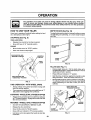
HOW TO USE YOUR TILLER
DEPTH STAKE (See Fig. 10)
Know how to operate all controls before adding fuel and
oil or attempting to start engine.
The depth stake canbe raised or toweredto aUowyou more
versatile tilling and cultivating, or to more easily transport
your tiller°
STOPPING
/ ......
(See Fig. 9)
TINES AND DRIVE
•
Release drive control bar to stop movement.
•
Move shift lever to "N" (neutral) position.
ENGINE
•
Move throttle control to "STOP" position,
•
Never use choke to stop engine.
POSITION
SHALLOWEST
TILLING
TILLING
DRIVE CONTROL BAR
"ENGAGED" POSITION
STAKE
DEPTH-_
,SHIFT
LEVER
FIG. 10
TILLING
DRIVE CONTROL BAR
"DISENGAGED" POSITION
FIG. 9
TINE OPERATION
- WITH
WHEEL
DRIVE
•
A_ways release drive control bar' before moving shift
lever into another position.
•
Tine movement is achieved by moving shift lever to "T"
(till) position and engaging drive control bar_
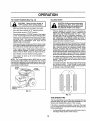
FORWARD
•
- WHEELS
ON LYiTINES
(See Fig. 11)
•
Release depth stake pin. Pull the depth stake up for
increased tilling depth, Place depth stake pin in hole of
depth stake to lock in position°
•
Place shift lever indicator in 'T' position.
°
Hold the drive control bar against the handle to start
tilling movement. Tines and wheels will both turn.
•
Move throttle control to"FAST" position for deep tilling,
To cultivate, throttle control can be set at any desired
speed, depending on how fast or slow you wish to
cultivate.
DEPTH STAKE PiN
"RELEASED" POSITION
\
STOPPED
Release drive control bar and move shift leverindicator
to "F" (forward) position. Engage drive control bar and
tiller will move forward_
REVERSE - WHEELS ONLY/TINES
"LOCKED"
POSITION
STOPPED
•
•
DO NOT STAND DIRECTLY BEHIND TILLER.
Release the drive control bar.
•
Move thJ:ottlecontrol to "SLOW" position.
.
°
Move shift lever indicator to "R" (reverse) position°
Hold drive control bar against the handle to start tiller
movement.
OUTER
SIDE SHIELD
NUT "B"
FIG. 11
10
TURNING
°
•
Releasethe drive controlbar,
•
Move throttle controlto "SLOW" position.
.
Place shift lever indicator in "F" (forward) position.
Tines will not turn.
•
•
Lift handle to raise tines out of ground.
Swingthe handle in the oppositedirectionyou wish to
turn, being careful to keep feet and legs away from
tines.
•
•
When you have completed your turn-around, release
the drive control bar and lower handle, Place shift lever
in 'T' (till) position and move throttle control to desired
speed. To begin tilling, hold drive control bar against
the handle°
The engine tn your unit has been shipped, from the
factory, already filled with SAE 30 summer weight oil,
With engine level, clean area around oil filler plug and
remove ptugo
•
Engine otl should be to point of overflowing. For
approximate capacity see PRODUCT SPECIFICATIONS" on page 3 of this manual, All oil must meet
A.PJo Service Classification SG
•
For cold weather operation you should change oil for
easier starting (See oil viscosity chart in the Customer
Responsibilities section of this manual)°
To change engine oil, see the Customer Responsibilities section in this manual
•
OUTER SIDE SHIELDS (See Fig. 11)
OIL
LEVEL
The front edges of the outer side shields are slotted so that
the shields can be raised for deep tillingand lowered for
shallow tilling to protect small plants from being buried,
Loosen nut "A" in slot and nut "B", Move shield to desired
position(both sides), Retighten nutsr
TRANSPORTING
DRAIN
PLUG
CAUTION: Before lifting or transporting, allow tiller engine and muffler to
cool. Dlsconnectsparkplugwire. Drain
gasoline from fuel tank.
OIL
FILLER
PLUG
FIG, 12
ADD GASOLINE
°
•
Release the depth stake pint Move the depth stake
down to the top hole for transporting the tiller, Place
depth stake pin in hole of depthstake to lock inposition,
This prevents tines from scuffing the ground_
•
Place shift lever indicator in "F" (forward) position for
transporting.
Hold the drive control bar against the handle to start
tiller movement, Tines will not turn.
•
•
Fill fuel tank.
Use fresh, clean, regular unleaded
gasoline° (Use of leaded gasoline will increase carbon
and lead oxide deposits and reduce valve life.
IMPORTANT;
WHEN OPERATING IN TEMPERATURES
BELOW 32°F (0°C), USE FRESH, CLEAN, WINTER
GRADE GASOLINE TO HELP INSURE GOOD COLD
WEATHER STARTING.
WARNING: Experience indicates that alcohol blended
fuels (called gasohol or using ethanol or methanol) can
attract moisture which leads to separation and formation of
acids during storage. Acidic gas can damage the fuel
system of an engine while in storage, To avoid engine
problems, the fuel system should be emptied before storage of 30 days or longer. Drain the gas tank, start the
engine and let it run until the fuel lines and carburetor are
empty, Use fresh fuel next season_ See Storage Instructions for additional information,
Never use engine or
carburetor cleaner products in the fuel tank or permanent
damage may occur.
Move throttle control to desired speed°
for the first ttme, study this section and
the'
SAFETY
RULES"
on page
CAUTION:
Before
operating
your2. tiller
Always release drive control bar before
moving shift lever Into another posi.
tion.
Don't back yourself into a solid obstruction such as a tree, fence, etco
,,,,
..........
iiH,i,lll LL
lll
CAUTION: Fill to within 1/2 inch of top
of fuel tank to prevent spills and to
allow for fuel expansion. If gasoline Is
accidentally spilled, move machine
away from area of spill. Avoid creating
any source of ignition until gasoline
vapors have dlsappearedo
l
BEFORE STARTING ENGINE
CHECK ENGINE OIL LEVEL (See Fig. 12)
IMPORTANT: BE VERY CAREFUL.NOT TO ALLOW DIRT
TO ENTER THE ENGINE WHEN CHECKING OR ADDING
OIL OR FUEL, USE CLEAN SAE 30 OR 10W30 WEIGHT
OIL AND STORE tN APPROVED, CLEAN, COVERED
CONTAINERS. ALL OILS MUST MEET A.PJ. SERVICE
CLASSIFICATION SGo USE CLEAN FILL FUNNELS.
Do not overfill. Wipe off any spilled oll
or fuelo Do not store, spill or use gasoline near an open flame.
IIHI
11
I.lllll .I,I
OPERATION
TILLING HINTS
TO START ENGINE (See Fig, 13)
...............................
I zt
,.o,,.o
oo°,.o,
,n !
...........
............
"OFF" posltlon when starting engine
*
Make sure spark plug wire is propedy connected°
.
.
.
Move shift lever indicator to "N" (neutral) position.
Place throttte control in "FAST" position°
Place choke control in "CHOKE" positionif the engine
iscoidoAwarm engine may not require choking to start.
.
Grasp starter handle with one hand and grasp the tiller
with other hand. Pull rope out slowly until engine
reaches start of compression cycle (rope will pull
slightly harder at this point).
Pull rope with a rapid, continuous, full arm stroke. Keep
a firm gdP on starter handle and let rope rewind slowly.
Do not let starter handle snap back against starter.
.
.
When engine starts, slowly move choke control on
engine halfway between 'CHOKE" and "RUN" positions and then to "RUN" position as engine warms up,
.
Move throttle control to desired running position.
Allow engine to warm up for a few minutes before
engaging tines.
NOTE: If at a high attitude (above 3000 feet) or in cold
temperatures (beIow 32°t=), the carburetor fuel mixture
may need to be adjusted for best engine performance. See
"TO ADJUST CARBURETOR in the Service and Adjustments section of this manual
_-,_=_
RECOIL STARTER
HANDLE
/
_
_
i
i,i, l/
i
H i,,,,
handling your tiller, start actual field
CAUTION:
Untilyou
areaccustomed
to
use
with thro_!e
In slow
position (toldway between FAST" and "IDLE").
.
SPARK
PLUG
i
•
Tilling is digging into, turning over, and breaking up
packed soil before planting_ Loose, unpacked soil
helps root growth_ Best tilling depth is 4' to 6'. A tiller
will also clear the soil of unwanted vegetation. The
decomposition of this vegetable matter enriches the
soil, Depending on the climate (rainfall and wind), it
may be advisable to till the soil atthe end of the growing
season to further condition the soil.
•
Soil cond itions are importantfor proper tilling. Tines wilt
not readity penetrate dry, hard soil which may contribute to excessive bounce and difficult handling of your
tiller, Hard soil should be moistened before tilling;
however, extremely wet soi! wilt "ball-up" or clump
during tilling, Wait until the soil is less wet in order to
achieve the best results. When tilling inthe fall, remove
vines and long grass to prevent them from wrapping
around the tine shaft and slowing your tilling operation.
For easier handling of your tiller, leave about 8 inches
of untilled soil between the first and second tilling
passes. The third pass will be between the first and
second (See Fig. 14).
Do not lean on handle.. This takes weight off the wheels
and reduces traction. To get through a really tough
section of sod or hard ground, apply upward pressure
on handle or lower the depth stake.
•
°
CHOKE
3
_---_
FIG. 13
FIG. 14
TINE SHEAR PINS
The line assemblies on your tiller are secured to the line
shaft with shear pins (See "TINE REPLACEMENT" in the
Service and Adjustments section of this manual).
If the tiller is unusually overloaded or jammed, the shear
pins are designed to break before internal damage occurs
to the transmission.
•
12
If shear pin (s) break, replace only with those shown in
the Repair Parts section of this manual.
OPEBATUON
CULTIVATING
OUTER VIEW OF TIRE
Cultivating is destroying the weeds between rows to prevent them from robbing nourishment and moisture from the
plants, At the same time, breaking up the upper layer of soil
crust will help retain moisture in the soil. Best digging depth
is 1" to 3'L Lower the outer side shields to protect small
plants from being buried,
•
F--""v_
. CLEVIS
Cultivate up and down the rows at a speed which will
allow tines to uproot weeds and leave the ground in
rough condition, promoting no further growth of weeds
and grass (See Fig. 15),
_,_"J_k-_
V..,.
_
_//
_'_
_
HAIRPIN
N
FIG. 16
•
k__.r-_ I
Replace clevis pin and hairpin clip on inside of wheel
and remove blocks.
•
Repeat preceding steps on left hand side.
NOTE: In extremely rough conditions and while cultivating,
the wheels should be moved outward on the axle for
increased stability,
A
"_.-_-_ i
INNER VIEW OF TIRE
FIG. 15
ADJUST WHEELS
Figs. 16 and 17)
•
•
FOR CULTIVATING
(See
Place blocks under righthand side of tillerand remove
hairpin clip and clevis pin from right hand wheel
Move wheel outwardapproximately 1 inch untilhole in
inner wheel hub lines up with inner hole in axle_
CLIP
FIG. 17
13
CUSTOMER
, m,
m
RESPONSIBILITIES
..................
MA,.TE.A.CE
SCHEDULE
_
/
,,o
RE, USER\',OE
,R
, Check Engine 0tl Level
kit
Change Engtne Oil
t_
if
0ii PivotPoints
....
!_1_2
......
_
I_
ii H,,
Inspect SparkArrester
Muffler
iii
Inspect Air Screen
if
w
INNN
"' ...................
V'
....,
Replace Air Cleaner Cartridge
_2
Clean EngineCylinderFins
b/
,mLm
ReplaceSpark P!ug
L...
,,,,
iHll
- ........................
•
J_
.................
Hllll
_tt,,,, ...............
if
..............
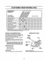
1 - Change more often when operaUng under a heavy load Qr in high amblent temperatures
2 - Set€lee mere often when operating In dirty or dusty conditions,
GENERAL
LUBRICATION CHART
RECOMMENDATIONS
The warranty on this unit does not cover items that have
been subjected to operator abuse or negligence. To
receive full value from the warranty, the operator must
maintain unit as instructed in thts manual.
* THROTTLE
CONTROL
Some adjustments will need to be made periodically to
properly maintain your unit.
** ENGINE
All adjustmentsin the Service and Adjustments sectionof
this manual should be checked at least once each
season.
* DEPTH
PIN
Once a year you should replace thespark plug,replace
air filter, and check tines and belts for wear. A new
spark plug and clean air filter assure proper air-fuel
mixture and help your engine runbetter and last longer'.
SHIELD
HINGE
BEFORE EACH USE
•
Check engine oil level.
•
,
Check tlne operation.
Check for loose fasteners.
* WHEEL,
HUB
LUBRICATION
* SAE 30 OR 10W30 MOTOR OIL
** REFER TO CUSTOMER RESPONSIBIUT1ES
Keep unitwell lubricated (See "LUBRICATION CHART").
14
* IDLER
BRACKET
"ENGINE"
SECTION
ILmTMES
Disconnect spark plug wire before performing any maintenance (except carburetor adjustment) to
prevent accidental starting of engine.
Prevent fires! Keep the engine free of grass, leaves, spilled oil, or fuel. Remove fuel from tank before
tipping unit for maintenance. Clean muffler area of all grass, dirt and debris.
Do not touch hot muffler or cylinder fins as contact may cause burns.
ENGINE
AIR CLEANER
LUBRICATION
Replace air cleaner cartridgeeverytwenty-five hours, more
often if engine is used in very dusty conditions,
.
Loosen air cleaner screws, one on each side of cover_
•
Remove air cleaner cover_
Change the oli after the first two hours of operation and
every 25 hours thereafter or at least once a year if the tiller
is not used for 25 hours in one year.
•
Check the crankcase oil level before starting the engine
and after each five (5) hours of continuoususe. Add SAE
30 motor oil or equivalent. Tighten oil filler plug securely
each timeyou checktheoillevel, SAE 5W-80 motoroil may
be used to make starting easier in areas where temperature
is consistently 32 ° F ((3°0) or lower.
Install new air cleaner cartridge. Clean and replace
cover. Tighten screws securely.
NOTE: Do not attempt to clean or oi!the paper cartridge.
AIR
CLEANER
SCREW
Determinetemperature range expected before oilchange°
All oil must meet API service classificationSG_
Q
Q
t
Carefully remove air cleaner cartridge. Be careful Do
not allow dirt_ordebris to fall into carburetor.
-
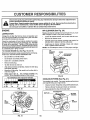
TO CHANGE ENGINE OIL (See Figs. 18 and 19)
m
(See Fig. 20)
COVER
AIR CLEANER
IDGE
Be sure tiller is on level surface,
Oil wilt drain more freely when warm°
Catch oil in a suitable container°
Remove drain plugo
Tip tiller forward to drain ell,
After oil has drained completely, replace oil drain plug
and tighten securely.
Remove oll filler plugo Be careful not to allow dirt to
enter the engineo
Refill engine with oil. See "CHECK ENGINE OIL
LEVEL in the Operation section of this manual,
FIG. 20
RECOMMENDED SAE VISCOSITY GRADES
COOLING
°F -20"
°C -29 °
0°
-18o
32"
0°
600
16°
80°
27°
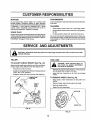
SYSTEM (See Fig. 21)
Your engine is air cooted. For properengine performance
and long life keep your engine clean.
•
Clean air screen frequently using a stiff.bristled brush°
° Remove blower housing and clean as necessary,
100°
38°
FIG. 18
•
Keep cylinder fins free of dirt and chaff,
CYUNDER FINS
/HOUSING
OIL
DRAIN
AIR
/
SCREEN
/BLOWER
MUFFLER _
OIL FILLER
PLUG
FIG. 19
FIG. 21
15
CUSTOMER
RESPONSIBILITIES
MUFFLER
TRANSMISSION
Do not operate tiller without muffler. Do not tamper with
exhaust system_ Damaged mufflers or spark arresters
could create a fire hazard. Inspect periodically and replace
if necessary. If your engine is equipped with a spark
arrester screen assembly, remove every 50 hours for
cleaning and inspection. Replace if damaged.
Your transmission issealed and wil! only require lubrication
if serviced°
CLEANING
•
°
Clean engine, wheels, finish, etc_ of all foreign matter.
Keep finishedsurfaces and wheels free of alt gasoline,
oil, etc.
•
Protect painted sulfaces with automotive type wax°
SPARK PLUG
Replace spark plugs at the beginning of each tilling season
or'after every50 hours of use, whichever comesfirst. Spark
plug type and gap setting is shown in "PRODUCT SPECIFICATIONS" on page 3 of this manual.
SERVICE
ZLLL"•..
II
I..I.
.'.'
Illlllll
lull".,
I II,,.
We do not recommend using a garden hose to clean your
unitunlessthe muffler, air fitter and carburetor are covered
to keepwater out. Water in engine can resultina shortened
engine life,
AND ADJUSTMENTS
II
IlUl.I
.I
I I,.ll
II
•
I
LI.
I..,I L'J/I
I'
............
CAUTION:
spark plug wires from spark plug and place wire where tt cannot come Into
contact
withDisconnect
plug.
.................
_
TILLER
TIRE CARE
IA................
TO ADJUST HANDLE HEIGHT (See Fig. 22)
CAUTION: When mounting tires, un.
less beads are seated, overlnflatton
can cause an exploslon_
Select handle height best suited for yourtilling conditions_
Handle height will be different when tilter digs into soil.
•
First loosen handle lock lever.
•
•
,,,,,,,,,,,,,,,,,,,,,
_......
illl
Handle can be positioned at different settings between
"HIGH" and "LOW" positions.
Retighten handle lock lever securely after adjusting°
/.
.,i
..... ,_,
/
F_
lul ,,
HHI
I I Ill
.f_:._
I
_
,,,,
.............
,
Keep tires free of gasoline or oil which can damage
rubber.
HANDLE
LOCK
•
•
Place blocks under transmission to keep tiller from
tipping.
Remove hairpin clip and clevis pin from wheel
Remove wheel and tire.
°
Repair tire and reassemble.
CLEVIS PIN
l
POSITION)
I ill
Maintain 20 pounds of tire pressure, If tire pressures
are not equal, tiller will pull to one side.
TO REMOVE WHEEL (See Fig. 23)
HANDLE (HIGH
POSITION)
"",'.."',
'_:'".
IL
•
•
._,'_'_
,,,
!
!
!
_
!
_'_
'\,
HAiRPiN CUP
FIG. 22
FIG. 23
16
ERVNCE AND ADJUSTMENTS
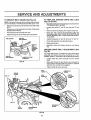
TO REPLACE GROUND
Figs. 24 and 25)
TO REMOVE BELT GUARD (See Fig, 24)
NOTE: For ease of removal, remove hairpinclipand clevis
pinfrom left wheel. Pullwheel out from tiller about 1 inch°
•
Remove two (2) cap nutsand washers from side ofbelt
guard°
•
Remove hex nut and washer from bottom of belt guard
(located behind wheel).
°
°
Pull belt guard out and away from unit,
Replace belt guard by reversing above procedure°
BELT GUARD
CAP NUT
AND WASHER
HE]< NUT
AND
WASHER
(LOCATED
BEHIND
TIRE)
CAP NUT
AND WASHER
Move left wheel and remove belt guard as described in
"TO REMOVE BELT GUARD",
•
Loosen belt guides "A" and "B" and also nuts "C" and
•
•
Remove old belt by slipping from engine pulley first,
Place new belt in groove of transmission pulley and
into engine pulley_ BELT MUST BE IN GROOVE ON
TOP OF IDLER PULLEY° NOTE POSITION OF BELT
TO GUIDES,
•
Tighten belt guides "A" and "B" and nuts "C" and "D".
°
Check belt adjustment as described below,
.
•
Replace belt guard°
Reposition wheel and replace clevis pin and hairpin
clip.
DRIVE BELT ADJUSTMENT
•
Loosen cable clip screw securing the drive control
cable_
•
Slide cable forward for less tension and rearward for
more tension until about 5/8 inch stretch is obtained
while the drive control bar is engaged°
•
Tighten cableclip screw securely,
BELT
CABLEC_P
DRIVE
CONTROL
CABLE
BELT
GUIDE "B"
\
LESS
TENSION
NUT "D"
IDLER
PULLEY
(See
For proper belt tension, the extension spring should have
about 5/8 inch stretch when drive control bar is in "ENGAGED" position, Thistension can be attained as follows:
FIG. 24
NUT "C"
BELT (See
,
GROUND
Fig. 25)
HAIRPIN CLIP AND
CLEVIS PiN
ENGINE
PULLEY
DRIVE
SPRING
TRANSMISSION
PULLEY
FIG. 25
17
SERVICE
TINE
REPLACEMENT
AND ADJUSTMENTS
(See Figs. 26, 27 and
•
28)
A
CAUTION:
Tines are sharp. Wear
gloves or other .......
protection when handling tines.
•
A badly worn tine causes your tiller to work harder and dig
more shallow+ Most important,worn tines cannot chop and
shred organic matter as effectively nor bury it as deeply as
good tines+ A tine this worn needs to be replaced.
To maintain the superb tilling performance of this
machine the tines should be checked for sharpness,
wear, and bending, particularlythetines which are next
to the transmission+ If the gap between the tines
exceeds 3-1/2 inches they should be replaced or
straightened as necessary.
New tines should be assembled as shown in Fig+28+
Sharpened tine edges witl rotate rearward from above.
O
NEW 3"[NE
WORN TINE
FIG. 26
FIG+27
SHARP EDGE
,_
(COUNTER
}TINE
ROTATION
SHEAR PIN
SHARP
EDGE
S
_
SHARP EDGE
,\
EDGE
HAIRPIN CLIP
SHARP
EDGES
FIG+ 28
18
;ERVICE AND ADJUSTMENTS
FINAL SETTING
ENGINE
•
TO ADJUST THROTTLE
(See Fig, 29)
•
•
CONTROL
Start engine and allow to warm for five minutes. Make
final adjustments with engine runningand drive control
bar in "DISENGAGED" position°
•
With throttle control lever in "SLOW" position, turn
needle valve in (clockwise) until engine begins to die
then turn out (counterclockwise) until engine runs
rough. Turn valveto a point midway between thosetwo
positions.
IDLE RPM ADJUSTMENT
CABLE
Loosen cable clamp screw to allow cable to move,
Move throttle control lever on upper handle to "FAST"
position_
Pull throttle cable out until engine bellcrank is back as
far as it will go.
Hold cable in this position and tighten clamp screw
securely.
°
•
-
To adjust idle RPM rotate throttle linkage counter_
clockwise and hold against stop while adjusting idle
speed adjustingscrew to obtain 1750 RPM Release
throttle linkage.
ACCELERATION TEST
CLAMP SCREW
THROTTLE
CABLE
•
High speed stop is factory adjusted. Do not adjust or
damage may result.
IMPORTANT: NEVER TAMPER WITH THE ENGINE
GOVERNOR, WHICH IS FACTORY SET FOR PROPER
ENGINE SPEED. OVERSPEEDINGTHE ENGINE ABOVE
THE FACTORY HIGH SPEED SETTING CAN BE
DANGEROUS. IF YOU THINK THE ENGINE-GOVERNED
HIGH SPEED NEEDS ADJUSTING, CONTACT YOUR
NEAREST SEARS SERVICE CENTER, WHICH HAS
PROPER EQUIPMENT AND EXPERIENCE TO MAKE ANY
NECESSARY ADJUSTMENTS,.
BELLCRANK
FIG. 29
ENGINE
TO ADJUST
CARBURETOR
Move throttle control lever from "SLOW" to "FAST"
position, If engine hesitates or dies, turn needle valve
out (counterclockwise) 1/8 turn. Repeat test and
continueto adjust, if necessary, until engine accelerates smoothly.
(See Fig. 30)
THROTTLE LINKAGE
TH ROTTLE STOP
The carburetor has been preset at the factory and adjust_
merit should not be necessary. However, minor adjustments may be required to compensate for differences in
fuel, temperature, altitude or Ioad_ If the carburetor does
need adjustment, proceed as folFows_
In general, turning the needle valve in (clockwise) decreases the supply offuel to the enginegivinga leanerfue!/
air mixture° Turning the needle valve out (counterclockwise) increases the supply of fuel to the engine giving a
richerfuel/air mixture.
IMPORTANT: DAMAGE TO THE NEEDLES AND THE
SEATS IN CARBURETOR MAY RESULT IF SCREWS
ARE TURNED IN TOO TIGHT_
IDLE SPEED
ADJUSTING SCREW
FIG. 30
PRELIMINARY SETTING
•
•
°
NEEDLE VALVE
Air cleaner assembly mustbe assembledtothe carburetor when making carburetor adjustments.
Be sure the throttle controlcable is adjusted properly
(see above).
With engine off turn needle valve in (clockwise) closing
it finger tight and then turn valve out (counterclockwise)
t-1/2 turns,
19
STORAGE
ENGINE OIL
immediately prepare your' tilter for storage at the end of the
season or if the unit will not be used for 30 days or more,
CAUTION:
Drain oil (with engine warm) and replace with clean oil.
(See "ENGINE" inthe Customer Responsibilities section of
this manual),
Never store the tiller with
where fumes may reach an open flame
gasoline In the tank inside a building
or spark, Allow the engine to cool
before storing in any enclosure°
CYLINDERS
TILLER
-
Remove spark plug,
Pour I ounce (29 ml) of oil through spark plug hole into
cylinder.
Pull starter handle slowly several times to distribute oil,
.
Clean entire tiller (See "CLEANING" in the Customer
Responsibilities section of this manual)°
•
Replace with new spark plug,
,
Inspect and replace belts, if necessary (See belt replacement instructions in the Service and Adjustments
section of this manual),
Lubricate as shown in the Customer ResponsibilitLes
section of this manual,
OTHER
Be sure that all nuts, bolts and screws are securely
fastened, Inspect moving parts for damage, breakage
and wear, Replace if necessary,
Touch up all rusted or chipped paint surfaces; sand
Ught_ybefore painting,
i.i
•
.
•
.
iHi m
•
,
,,, ...............................
,,,
IMPORTANT:
IT IS IMPORTANT TO PREVENT GUM
DEPOSITS
FROM FORMING
IN ESSENTIAL
FUEL
SYSTEM PARTS SUCH AS THE CARBURETOR,
FUEL
FILTER, FUEL HOSE, OR TANK DURING STORAGE.
ALSO, EXPERIENCE
INDICATES
THAT ALCOHOL
BLENDED
FUELS
(CALLED
GASOHOL
OR USING
ETHANOL OR METHANOL) CAN ATTRACT MOISTURE
WHICH LEADS TO SEPARATION AND FORMATION OF
ACIDS DURING STORAGE. ACIDIC GAS CAN DAMAGE
THE FUELSYSTEM OF AN ENGINE WHILE IN STORAGE.
•
Start the engine and let it run until the fuel lines and
carburetor are empty,
Never use engine or carburetor cleaner products in the
fuel tank or permanent damage may occur,
Use fresh fuel next season,
•
•
Replace your gasoline can if your can starts to rust.
Rust and/or d_rtin your gasoline will cause problems_
•
if possible, store your unit indoors and cover it to give
protection from dust and dirt,
Cover your unit with a suitable protective cover that
does not retain moisture, Do not use plastic. Plastic
cannot breathe which allows condensation to form and
will cause your unit to rusL
IMPORTANT: NEVER COVER TILLER WHILE ENGINE
AND EXHAUST AREAS ARE STILL WARM.
FUEL SYSTEM
Drain the fuel tank.
E)onot store gasolinefrom one season to another,
•
•
ENGINE
•
•
NOTE: Fuel stabilizer is an acceptable alternative in
minimizing the formation of fuel gum deposits during storage. Add stabilizer to gasoline in fuel tank or storage
container, Always follow the mix ratio found on stabilizer
container. Run engine at least 10 minutes after adding
stabilizer to allow the stabilizer to reach the carburetor. Do
not drain the gas tank and carburetor' if using fuel stabilizer.
20
TFtOUEI;LESHOOT NG POINTS
ii
JLLJII
PROBLEM
CAUSE
CORRECTION
Will not start
1,
2
3,
4,
5,
Outoffuel.
Engine not "CHOKED" properly,
Engine flooded,
Dirty air cleaner
Water In fuel,
1,
2,
3,
4o
5,
6,
7,
8,
9.,
Clogged fuel tank
Loose spark plugwire
Bad spark plug or Improper gap,
Carburetor out of adfustment
6
Fill fuel tank.
See "TO START ENGINE" in Operation section.
Watt several minutes before attempting to start
Replace air cleaner cartridge,
Drain fuel tank and carburetor, and refill tank with fresh
gasoline.
Remove fuel tank and clean_
7_
8.
9,
Make sure spark plug wire Is seated properly on plug
Replace spark plug or adjust gap.
Make necessary edjustments_
Hard to start
1_
2,
3
4,
5.
6
Throttle control not set properly,
Dirty air cleaner,
Bad spark plug or improper gap,
Stale or dirty fuel
Loose spark plug wire.
Carburetor outof adjustment,
1.
2,
3,
4,
5.
6.
Place throttle control fn =FAST" position,
Replace air cleaner cartridge,
Replace spark plug or adjust gap,
Drain fuel tank and refill wlth fresh gasoline.
Make sure spark pfug wire Is seated property on plug,
Make necessary adjustments,
Loss of power
1,.
2,
3,
4,
5.
6o
7r
Engine Is overloaded
Dirty air cIeaner,
Low oil leve!/dirty oil.
Faulty spark plug,
O11in fuel,
Stale or dirty
fuel.
Water In fuel,
t4
2,
3,
4o
5,
6,
7,
8
9,
10o
11.
12.
13.
Set depth stake for shallower tilling
Replace air cleaner cad.ridge,
Check oll leveltchange oi!.
Clean and regap or change spark plug,
Drain and clean fuel tank and refill, and clean carburetor,
Drain fuel tank and reft{Iwith fresh gasoline
Drain fuel tank and carburetor, and refIlt tank with fresh
gasoline,
8, Remove fuel tank and clean,
9, Connect and tighten spark plug wire
10. Clean engine air screen.,
11, Clean!replace muffler,
12,. Make necessary adjustments
13, Contact an authorized service center,
Cfogged fuel tank,
Spark plug wire loose.,
Dirty engine alr screen,
Dtrtytclogged muffler.
Carburetor out of adjustment
Poorcompressfon.
Excessive bounce/
difficult handling
1,
Ground too dry and hard,
I,
Soil balls up or clumps
1.
Ground too wet,
1. Waltfor morefavorable sellconditions,
Engine rune but tiller
won't move
1,
2.
3.
Drive control bar Is not engaged.
V-belt not correctly adjusted,
V-belt Isoff pulley(s),
1,
2,
3.
Engage drive control
Inspect/adjust V-belL
inspect V-beltr
Engine runs but labors
when tllllng
1,
2
3
Tilling too deep,
Throttle control not properly adjusted.
Carburetor out of adjustment
12,
3,
Set depth stake for shallower tilling,
Check throttle control setting,
Make necessary adjustments,
Shear pin(s) broken
!.
Replace shear pin(s),
Tines wlll not rotate
21
Moisten ground or welt for more favorable soil
conditions,
REPAIR PARTS
5 HP 14" TILLER
- - MODEL
NUMBER
917.299751
HANDLES
9
2
1
30
29
15
KEY
NO.
1
2
3
4
5
6
7
8
9
10
11
12
13
14
15
16
17
18
19
20
DESCRIPTION
KEY
NO.
Cap, Sleeve
Grip, Handle
Grommet, Handle
Bar, Drive Control Assembly
Cap, Vinyl
Panel, Control
Bushing, Split
*Screw, Mach. Pan Head. C.R_
#10-24 x 1/2
STD533125 * Bolt, Carriage
5/t6-18 UNC x 2-3/8 Gr° 5
110646X
Handle, Grip
STD624003 * Clip, Hairpin
81328
Bo_t, Shoulder
11074tX
Handle, Shift
109313X
Grommet, Rubber
t10702X
Rod, Shift
STD533710 *Bolt, Carriage 3/8-16xl Gro5
109229X
Lock, Handle
STD541437 *Nut, Centerlock 3/8-16
19131611
Washer 13/32xl xll Ga.
109228X
Lever, Lock, Handle
21
22
23
PART
NO.
110707X
110674X
110673X
t27254X
6712J
126948X
110641X
STD511005
24
25
26
27
28
29
30
PART
NO.
1212i3X
121145X
86777
9484R
73970500
1 t 0675X
STD541025
STD551125
STD541462
t27012X
133893
120431X
127795
121859X
DESCRIPTION
Handle, Assemble
Clip, Plastic, Cable
Screw, Hex, Washer Hd, Slotted
#10-24 x 1/2
Clip
Locknut, Hex, Flange
Clutch, Cable
* Nut, Hex 1/4-20
* Washer, Lock 1/4
* Nut, Keps #10-24
Throttle, Control
Manual, Owner's
Decal, Hand Placement
(Control Panel)
Decal, Control Panel
Decal, Caution, Clutch
(Control Panel)
* STANDARD HARDWARE -- PURCHASE LOCALLY
NOTE: All component dimensions given in U.S. inches_
1 inch = 25°4 mm
22
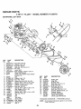
REPAIR PARTS
5 HP 14" TILLER
MAINFRAME,
LEFT
- - MODEL
NUMBER
917.299751
SIDE
38
12
36
17 18
20
21
KEY
NO.
1
2
3
4
5
6
7
8
9
10
11
12
13
14
15
16
17
18
19
20
21
22
23
PART
NO,
STD541431
STD551137
STD541037
74930568
STD57 t 8 ! 0
1101!1X
STD532505
8700J
86777
9484R
STD551125
STD541025
STD503103
120938X
STD551031
100473M
STD541031
110651X
2649M
1 t0653X
13! 691
104214X
102190X
109208X
795R
24 126875X
25 STD624003
26 131159X417
27 132672
15
DESCRIPTION
* Nut, Keps 5/16-18
* Washer, Lock 3/8
* Nut, Hex 3/8-16
Bolt, Hex 5/16-18 x 4-1/4
* Pin, Roll
Lever, Shift
* Bolt, Carriage 1/4-20 x 1/2 Gr. 5
Plate, Shift Indicator
Screw, Hex, Washer Head, Slotted
#I0-24 x 1/2
Clip
* Washer, Lock 1/4
* Nut, Hex 1/4-20
* Screw, Set, Hex 5/16-18 x 3/8
Spacer, Split 0.327 x 0.42 x 2.68
*Washer 11/32 x 11/16x 16Gao
Sheave, Transmission
*Nut, Hex 5/16-18
Spacer, Split 0,327 x 0.42 x 1.75
Key, Square 3/16 x 1-1/8
Guard, Pinch Point
Spacer, Split 0.327 x 0A2 x 1.627
Nut, Cap 5/16-18
Tire
Rim
Tire Valve
Rivet, Drilled
* Clip, Hairpin
Guard, Belt
Belt, V
26
152#2
23
24
25
KEY
NOo
28
29
30
31
32
33
34
35
36
37
38
---
PART
NO.
104679X
12000032
105611X
t02384X
102141X
STD523710
102383X
74760524
102331X
130816
131558
102180X
133668
DESCRIPTION
Pulley, Idler
Ring, Klip
Bracket, idler
Bolt, Hex 5/16-16 x 12
Shaft, Idler Arm
* Bott, Hex 3/8-16 x I
Counterweight, L.Ho
Bolt, Hex 5/16-18 x 1-1/2
Bracket, Reinforcement, L.H.
Sheave, Engine
Bracket, Guard Belt
Decal, Shift Indicator
Decal, Logo (Belt Guard)
*STANDARD HARDWARE - - PURCHASE LOCALLY
NOTE: All component dimensions given in U,S inches,
1 inch = 25.4 mm
23
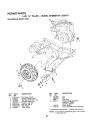
REPAIR PARTS
5 HP 14" TILLER
MAINFRAME,
RIGHT
PART
NO.
8TD541431
102332X
74760524
102173X
STD55 ! 137
STD541037
S'rD624003
126875X
NUMBER
917.299751
SIDE
7
KEY
NO.
1
2
3
4
5
6
7
8
- - MODEL
6
DESCRIPTION
KEY
PART
NO.
NO.
9 102190X
109208X
795R
10 131877
* Nut, Keps 5/16-18
Bracket, Reinforcment
Bolt, Hex 5/'!6+18 x 1+1/2
Counter Weight, R.H.
*Washer +, Lock 3/8
*Nut, Hex 3/8-16
* Clip, Hairpin
Rivet, Drilled
.
+
132402
110719X
DESCRIPTION
Tire
Rim
Tire Valve
Engine, Briggs & Stratton
Model No. 130202,
Type No+3273.01
Decal, Engfne
Decal, Operation and Lubrication
* STANDARD HARDWARE -+PURCHASE LOCALLY
NOTE:
24
All component dimensions given in U.Sinches,
1 inch = 25.4 mm
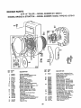
REPAURPARTS
5 HP 14" TILLER .. - MODEL NUMBER
917.299751
TRANSMISSION
25
25
11
6
5
48
51
KEY
PART
NO.
NO.
1 132718
121147X
3
4
5
6
7
8
9
10
1!
12
13
14
15
16
17
18
19
20
1062! 1X
5020J
1370H
102113X
102110X
4895H
t02136X
7392M
100371K
'i 06160X
102107X
8353J
12000039
t02!09X
104t59X
4358J
12000040
1O2114X
21
22
23
24
25
102115X
6803J
102111X
STD551143
STD551143
DESCRIPTION
Transmission Assembly
(Includes Key Nos. 2-52)
Gearcase, L°H. w/Bearing
(Includes Key No. 4)
Gasket, Gearcase
Bearing, Needle
Washer, Thrust 5/8 x t.10 x 1/32
Pinion, Input
Shaft, Input
Bearing, Needle
Washer, Seal
Ball, Steel
Spring, Shift, Fork
O-Ring
Arm, Shift
Fork, Shift
Ring, Klip
Shaft, Shift
Spacer, Split
Washer
Ring, Klip
Gear, Assembly, Reverse Idler
(Includes Key Nos. 21 and 22)
Gear, Reverse Idler
Beadng, Needle
Shaft, Reverse Idler
* Washer, Lock 7/16
*Nut, Hex 7/16-20
KEY
NO.
26
27
28
29
30
31
32
33
34
35
36
PART
NO.
102128X
102100X
106390X
102134X
109204X
102t06X
106388X
102121X
102112X
102101X
106141X
37
38
39
40
41
42
43
44
45
46
47
48
4422J
t06t42X
105345X
!05346X
8358J
4220R
106146X
9672R
102144X
9676R
9674R
t21745X
49
50
51
52
--
132688
106147X
17580408
STD54103t
6066J
DESCRIPTION
O-Ring
Bearing, Shaft, Ground Drive
Spacer 0.765 x 1.125 x 1.23
Chain #35-50 Pitch
Ground Shaft Assembly
Bearing, Shaft, GroundDrlve
Spacer 0.70 x 1o00x 1.150
Sprocket and Gear Assembly
Shaft, Reduction (2nd)
Screw, Whiz, Lock 5/16-18 X3-1/2
Sprocket Assembly w/Bearing
(Includes Key Noso 37 and 38)
Bearing, Needle
Sprocket, Tine
Gear, Cluster, Red 1st & 2rid
Gear, Reverse
Shaft, Reduction (1st)
Washer, Thrust
Spacer 1.01 x 1.75 x 0°760
Cup, Formed
Ring, Spiral
Seat, Ring, Rubber
Seal, Oil
Gearcase, R.H. w/Bearing
(Includes Key No. 8)
Shaft, Tine
Chain, Roller #50-50 Pitch
Screw 1/4-20 x 1/2
Nut, Hex 5/t6-18
Grease, Plastilube #1
* STANDARD HARDWARE - - PURCHASE LOCALLY
25
NOTE_ Atl component dimensions given in U.S. inches.
1 inch = 25.4 mm
REPAIR PARTS
5 HP 14" TILLER
-- MODEL
NUMBER
917.299751
TINE SHIELD
2
10
8
of
18
28
24
23
"
"
29
"
19
21
KEY
NO,
1
2
3
4
5
6
7
8
9
10
11
12
13
14
15
16
17
18
PART
NO,
98000129
104086X417
8393J
12000036
72110508
8394J
8392J
t09230X
102152)(4t7
STD533107
STD541031
STD551131
72110510
124343X
104101X4t7
8TD54t025
STD551125
STD5325t2
15
KEY
NO.
19
20
21
22
23
24
25
26
27
28
29
---
DESCRIPTION
Nut, Flange 5/16-t8
Shield, Side, Outer L. H.
Pin, Stake, Depth
Ring, Klip
Bolt, Carriage 5/16-18 x t
Spring
Bracket, Latch
Spring, Depth Stake
Shield, Tine
*Bolt, Carriage 5/16-18 x 3/4 Gr 5
*Nut, Hex 5/16-18
*Washer, Lock 5/16
Bolt, Carriage 5/16-18 x 1-1/4
Bracket, Shield Tlne
Shield, Side, Outer R.H.
*Nut, Hex 1/4-20
*Washer, Lock I/4
*Bolt, Carriage 1/4-20 x 1-1/4 Gr+5
DESCRIPTION
PART
NO+
102701X
Hex 3/8-16
STD541037 * NGdtP,
102156X
Stake, Depth
74930632
Bolt, Hex 3/8-16 x 2
4440J
Hinge
STD532505 * Bolt, Carriage 1/4-20 x 1/2 Gr. 5
6712J
109227X
102686X417
Shield, Leveling
120588X
Pin, Hinge
104085X417
Shield, Side
127802
Decal, Tine Shield
120075X
Decal, Warning (Leveling Shield)
* STANDARD HARDWARE - +PURCHASE LOCALLY
NOTE= All component dimensions given in U.S+ inches+
i inch = 25.4 mm
26
REPAIR PARTS
5HP
14" TILLER
-- MODEL
NUMBER
917.299751
TINES
5
3
11
2_
9
9
6
7
6
KEY
NO.
t
2
3
4
5
6
PART
NO.
73610600
STD551137
4460J
74610616
132673
STD624008
KEY
NO.
DESCRIPTION
Nut, Hex 3/8-24
* Washer, Lock 3/8
Tine, Outer, R.H°
Bolt, Hex 3/8-24x 1
Pin, Shear
* Clip, Hairpin
7
8
9
10
11
PART
NO.
132722
6555J
6554J
132721
4459J
DESCRIPTION
Assembly, Hub and Plate, R.H,
Tine, Inner, R.H.
Tine, Inner, L.H.
Assembly, Hub and Plate, LH.
Tine, Outer, L,Ho
* STANDARD HARDWARE - - PURCHASE LOCALLY
NOTE: All component dimensions given in UoS. inches.
1 Inch = 25.4 mm
27
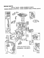
REPAIR PARTS
5 HP 14" TILLER
ENGINE,
BRIGGS
& STRATTON
- - MODEL
NUMBER
917.299751
- - MODEL
NUMBER
130202, TYPE
7
36
6t5
(_ 614
230
{2oI:,'91
=
(_22
28
35
NO. 3273-01
REPAIR PARTS
5 HP 14" TILLER
ENGINE,
BRIGGS
& STRATTON
- - MODEL
NUMBER
917.299751
- - MODEL
NUMBER
130202, TYPE
NO. 3273-01
191
163
526
621
12zA
392
124
29
REPAIR PARTS
5 HP 14" TILLER
ENGINE,
BRIGGS
& STRATTON
- - MODEL
NUMBER
917.299751
- - MODEL
NUMBER
130202,
TYPE NO. 3273-01
7I
73
56
37
KEY PART
NOo NO_
1
2
395990
297565
3
5
7
8
9
10
11
12
18
I9
299819
211542
272157
294178
27549
94621
66578
270080
270125
270126
94221
93369
94387
93448
492088
230978
297602
297603
20
21
294606
66768
13
14
t5
16
KEY PART
NO, NO.
DESCRIPTION
*
*
*
*
*
Cylinder Assembly
Bushing,Cylinder (Special Tools
Required for Installation)
Seal, Oi!
Head, Cylinder
Gasket, Cylinder Head
Breather, Valve Chamber
Gasket, Valve Cover
Screw, Sems, Breather Mounting
Grommet, Breather Tube
Gasket, Crankcase, Standard .015"
Gasket, Crankcase .005 °
Gasket, Crankcase .009"
Screw, Cylinder Head 2-3f32"
Screw, Cylinder Head 2-15/32"
Plug, Pipe
Plug, Pipe, Hex Socket Head
Crankshaft
Crankshaft Gear Pin
Cover Assembfy, Crankcase
Bushing, Crankcase Cover (Special
Tools Hequired for installation)
Sea! Oi!
Pug, Oil Filler
22
93032
23
24
25
297229
222698
298904
298905
298906
298907
298982
299742
298983
298984
298985
26026
298909
298908
299430
390459
26
27
28
29
3O
31
32
83
30
221890
221876
92296
211119
DESCRIPTION
Screw, Seres, Crankcase Cover
Mounting (Uses: 93656 Stud, and
90832 Washer, Lock)
Flywheel, Magneto
Key, Flywheel
Piston Assembly, Standard
Piston Assembly .010" Oversize
Piston Assembly .020" Oversize
Piston Assembly .030" Oversize
Ring Set, Piston, Standard
Ring Set, Piston, Chrome, Standard
Ring Set, Piston .010" Oversize
Ring Set, Piston .020" Oversize
Ring Set, Piston .030" Oversize
Loc[_, Piston Pin
Pin Assembly, Piston, Standard
Pin Assembly, Piston .005 Over
Rod Assembly, Connect!ng
Rod Assembly, Connecting,
.020" Undersize Crankpln Bore
Dipper, Connecting Rod
Lock, Connecting Rod Screw
Screw, Connecting Rod
Valve, Exhaust
REPAIR PARTS
5 HP 14" TILLER
ENGINE,
KEY PART
NO_ NO.
34
35
36
37
40
45
46
52
55
56
261044
260552
26478
222443
93312
260642
212733
271936
299431
295871
57
58
59
60
65
490179
66884
490653
490652
94!28
66
67
68
70
71
73
74
75
81
90
95
96
97
108
118
124
127
127A
t49
152
t53
154
399671
394897
63770
298799
394506
221923
93758
224061
222263
49261!
93499
223793
490048
491177
231533
93357
220352
223789
26336
260575
490589
93527
163
180
18t
190
191
200
201
202
202A
203
204
205
209
216
219
220
222
223
224
227
230
256
257
300
304
305
271935
490554
494559
94094
272410
223886
262280
262270
262470
280720
222962
231520
262282
262359
391737
221551
490648
223455
93491
490374
222450
223813
93543
393615
490169
93158
BR|GGS
& STRATTON
- - MODEL
NUMBER
917.299751
- - MODEL
NUMBER
130202,
KEY PART
NO. NO.
DESCRIPTION
Valve, Intake
Spring, Intake Valve
Spring, Exhaust Valve
Guard, Fiywhee!
Retainer, Valve Spring
Tappet, Valve
Gear, Cam
* Gasket, Carburetor Mounting (2)
Housing, Rewind Starter
Pulley, Rewind Starter
(Includes 63 Long Rope)
Spring, Rewind Starter
Rope, Rewind Starter
insert, Starter Handle
Handle, Rewind Starter
Screw, Seres, Stamped Steel Housing
Mounting
Clutch Assembly, Rewind Starter
Housing, Starter Clutch
Bell, Clutch
Ratchet, Rewind Starter
Washer, Clutch Retainer
Screen, Starter Pulley
Screw, Hex Head
Washer, Spring
Lock, Screw
Carburetor Assembly
Screw, Seres, Throttle Valve to Shaft
Throttle, Carburetor
Shaft and Lever, Throttle
Valve Group, Choke
Valve, Needle
Screw, Hex Head
Plug, Welch
Plug, Welch, Mixing Chamber
Spring, Needle Valve
Spring, Throttle Adjustment
Screw Assembly
Screw, Machine, Round Head
#5-40 x 5/'8"
Gasket, Air Cleaner Mounting
Tank Assembly, Fuel
Cap, Fuel Tank
Screw, Seres, Fuel Tank Mounting
* Gasket, Fuel Tank Mounting
Guide, Air
Link, Governor
Link, Throttle
Link, Throttle
Crank, Bell
Bushing, Governor Lever, Flat
Screw, Shoulder
Spring, Governor
Link, Choke
Gear, Governor
Washer, Thrust
Bracket, Control
Lever, Governor Control
Rivet, Governor Control Lever Mounting
Lever Assembly, Governor
Washer, Governor Lever
Crank, Bell
Screw, Sems, FillisterHead
Muffler, Exhaust
Housing, Blower
Screw, Blower Housing Mounting
306
307
308
333
335
337
346
356
358
363
221511
93490
221512
397358
93414
802592
93705
398808
397145
19069
373
383
392
394
414
432
433
434
435
467
526
527
528
529
536
542
552
562
592
608
611
613
614
615
616
621
634
635
655
676
679
680
741
851
869
870
92987
89838
262328
270026
220982
221377
93265
2t 0959
93141
280715
94409
223786
231550
67838
494279
93572
23t079
92613
231082
390463
391813
93935
93306
93307
231077
396847
271853
66538
222598
393757
270382
221839
261696
221798
211787
211172
871
262001
63709
916
966
967
968
969
971
987
995
1012
10t6
1019
280321
490074
491588
223765
490073
94018
398970
491577
490507
490817
491100
TYPE NO. 3273-01
DESCRIPTION
Shield, Cylinder
Screw, Seres, Cylinder Shield Mnt,,
Cover, Cylinder Head
Armature Assembly
Screw, Sems, Armature Mounting
Plug, Spark
Screw, Sems
Wire, Ground
Gasket Set
Flywheel Puller
(Optional Accessory)
Nut, Hex
Wrench, Spark Plug
Spring, Fuel PumpDfaphragm
Diaphragm
Washer
Cap, Spring
Pin, Diaphragm Cover
Cover, Diaphragm
Screw, Diaphragm Cover
Knob, Control
Screw, Seres, Tank Bracket Mnto
Clamp, Breather Tube
Tube, Breather
Grommet, Breather Tube
Air Cleaner Kit
Screw
Bushing,Governor Crank, 1/4" IoD.
Bolt, Governor Lever
Nut, Hex #!0-24
Starter Assembly, Rewind
Fuel Pipe and Clip Assembly
Screw, Hex Head, Shoulder
Cotter, Hair Pin
Retainer, E-Ring
Crank Governor, 1/4" Diameter
Switch, Stop
Washer, Throttle Shaft, Foam
Elbow, Spark Plug
Anchor Spring
ueflector, Exhaust, Side Outlet
Washer, Choke Shaft, Foam
Washer, Choke Shaft, Brass
Gear, Timing
Cable, Temminal, Ignition
Seat, Intake Valve, Standard
Seat, Exhaust Valve, Standard (See
Repair Manual For Options)
Guide, Exhaust Valve
Guide, Intake Valve
ee Repair InstructionManual)
ear Rack, Governor
Base, Air Cleaner
Filter, Air
Cover, Air Cleaner
Screw, Cover Mnt. (lncl. Grommet)
Screw, Air Cleaner
Seal, Throttle Shaft
Bracket, Link
Link, Retainer
Spacer
Label Kit
*Indicates Parts included In Gasket Set (397145)
NOTE: Allcomponent dimensions given In U,Soinches
1 inch = 254 mm
31
[RRFTXMRN
S_ A/k S
5.0 HP
14 INCH TINE WIDTH
REAR TINE TILLER WITH
COUNTER ROTATING TINES
OWNER'S
MANUAL
MODEL NO.
917.299751
Each tiller has Its own model number. Each engine has its own model
number.
The model number for your tiller will be found on a plate attached to the
top of the transmission,
The model number for your engine will be found on the blower housing of
the engine adjacent to the spark plug.
All parts listed herein may be ordered from any Sears, Roebuck, and Co_
Service Center and most Retail Stores.
WHEN ORDERING REPAIR PARTS, ALWAYS GIVE THE FOLLOWING INFORMATION:
HOW TO ORDER
REPAIR PARTS
• PRODUCT - REAR TINE TILLER
• MODEL NUMBER - 916.299751
• ENGINE MODEL NUMBER - 130202, TYPE NUMBER 3273-01
• PART NUMBER
• PART DESCRIPTION
Your Sears merchandise has added value when you consider Sears has
service units nationwide staffed with Sears trained technicians., professional technicians specifically trained to insure that we meet our pledge
to you, we service what we sell.
Sears, Roebuck and Co., Chicago, IL 60684 U.S.A.
i
133893 Rev. 1
10.21.91
ii
i
HlllJ
i
HH,ll
llll
,ll,
II
H,,I
I m
I Nil
Ill'
II,
" ...............
I,Ill
,,lllll
L
PRINTED IN THE U,SoA.