1
OWNER'S
MANUAL
MODEL NO.
917.299691
Cauti6n;
Read and follow
all Safety Rules
and Instructions
Before Operating
This Equipment
5.0 HP
17 INC TINE WIDTH
COUNTER ROTATING TINES
EAR TI
TILLER
• Assembly
, Operation
• Maintenance
• Service and Adjustment
• Repair Parts
Sears, Roebuck
and Co., Chicago,
IL 60684 U.S.A.
SAFETY RULES
Safe Operation
Practices
for Walk-Behind
Powered
Rotary
Tillers
TRAINING
, Read the operating and service instruction manual carefuIly. Be thoroughly familiar with the controls and the
proper use of the equipment. Know how to stop the unit
and disengage the controls quickly.
• Never allow children to operate the equipment. Never
allow adults to operate the equipment without proper
instruction.
, Keep the area of operation clear of all persons, particularly small children, and pets.
PR E PARATIO N
• Thoroughly inspect the area where the equipment is to be
used and remove all foreign objects.
, Disengage all clutches and shift into neutral before
starting the engine (motor),
° Do not operate the equipment without wearing adequate
Outer garments. Wear footwear that wilt improve footing
on slippery surfaces.
• Stop the engine (motor) when leaving the operating
position, before unclogging the tines, and when making
any repair, adjustments, and inspections.
• Take all possible precautions when leaving the machine
unattended. Disengage the power take-off, lower the
attachment, shift into neutral, stop the engine, and
remove the key.
• Before cleaning, repairing, or inspecting, shut off the
engine and make certain al! moving parts have stopped.
Disconnect the spark plug wire, and keep the wire away
from the plug to prevent accidental starting. Disconnect
the cord on electric motors.
, Do not run the engine indoors; exhaust fumes are dangerous.
• Never operate the tiller without proper guards, plates, or
other safety protective devices in place.
+ Keep children and pets away.
• Do not overload the machine capaci_ by attempting to till
too deep at too fast a rate.
• Handle fuel with care; it is highly flammable.
Use an approved fuel container,
,
,
Never add fuel to a running engine or hot engine.
Fill fuel tank outdoors with extreme care. Never fill
fuel tank indoors.
•
Replace gasoline cap securely and clean up spilled
fuel before restarting.
• Use extension cords and receptacles as specified bythe
manufacturer for all units with electric drive motors or
electric starting motors.
• Never attempt to make any adjustments while the engine
(motor) is running (except where specifically recom+
mended by manufacturer)+
OPERATION
, Never operate the machine at high speeds on slippery
surfaces. Look behind and use care when backing.
, Never allow bystanders near the unit.
• Use only attachments and accessories approved by the
manufacturer of the tiller (such as wheel weights,
counterweights, cabs, and the like).
• Never operate the tiller without good visibility or light.
+ Be careful when tilling in hard ground. The tines may
catch in the ground and propel the tiller forward. If this
occurs, let go of the handlebars and do not restrain the
machine.
MAINTENANCE
AND STORAGE
" Do not put hands or feet near or under rotating parts.
• Keep machine, attachments,
working condition,
• Exercise extreme caution when operating on or crossing
gravel drives, walks, or roads. Stay alert for hidden
hazards or traffic. Do not carry passengers.
° Check shear bolts, engine mounting bolts, and other
bolts at frequent intervals for proper tightness to be sure
the equipment is in safe working condition,
• After striking a foreign object, stop the engine (motor),
remove the wire from the spark plug, thoroughly inspect
the tiller for any damage, and repair the damage before
restarting and operating the tiller.
, Never store the machine with fuel in the fuel tank inside
a buitding where ignition sources are present, such as hot
water and space heaters, clothes dryers, and the like.
Allow the engine to cool before storing in any enclosure.
• Exercise caution to avoid slipping or falling.
• Always refer to the operator's guide instructions for
important details if the tiller isto be stored for an extended
period.
• If the unit should start to vibrate abnormally, stop the
engine (motor) and check immediately for the cause.
Vibration is generally a warning of trouble.
-IMPORTANT
and accessories
in safe
-
Cautions, [mportants, and Notes are a means of attracting attention to important or critical information in this manual,
_for
this
symbol to_
IMPORTANT,"
USED TO ALERT
IS A POSSIBILITY
OF DAMAGING
YOU THAT THERE
THIS EQUIPMENT.
NOTE: Gives essential information that will aid you to
better understand, incorporate, or execute a particular
set of instructions.
PRODUCT
NGRATULATIONS
onyourpurchase
ofa SearsTiller.
_s beendesigned,engineered
and manufactured
to
you the best possibledependability
and perform-
SPECIFICATIONS
HORSEPOWER:
5.0 H.P.
DISPLACEMENT:
12.57 cu. in.
GASOLINE CAPACITY:
3 QUART
(UNLEADED)
ase read and retain this manual. The instructions will
_ble you to assemble and maintain your tiller properly.
/ays observe the "SAFETY RULES".
OIL (20 OZ. CAPACITY):
SAE 30W
(SAE 10W 30)
MODEL
NUMBER
SPARK PLUG (GAP .030 IN.):
Champion
RJ19LM
;e.
_uid you experience any probiems you cannot easily
ledy, please contact your nearest authorized Service
qteriDepartment.
They have competent, well-trained
hnicians and the proper tools to serwce or repair this
t.
917.299691
SERIAL
NUMBER
DATE OF
PURCHASE
MAINTENANCE
AGREEMENT
A Sears Maintenance Agreement is available on this
product. Contact your nearest Sears store for details.
THE MODEL AND SERIAL NUMBERS WILL BE
FOUND ON THE MODEL PLATE ATTACHED TO
THE TOP OF THE TRANSMISSION.
CUSTOMER
YOU SHOULD RECORD BOTH SERIALNUMBER
AND DATE OF PURCHASE AND KEEPIN A SAFE
PLACE FOR FUTURE REFERENCE.
RESPONSIBiLITiES
• Read and observe the safety rules.
• Follow a regular schedule in maintaining,
and using your tiller.
• Follow the instructions under "Maintenance"
age" sections of this OwneCs Manual.
MMtTED ONE YEAR WARRANTY
ON CRAFTSMAN
caring for
and "Stor-
TILLER
For one year from date of purchase, when this Craftsman Tiller is maintained, lubricated, and tuned up according to
the operating and maintenance instructions in the owner's manuaf, Sears will repair free of charge any defect in
material or workmanship.
This Warranty does not cover:
•
Expendable items which become worn during normal use, such as tines, spark plugs, air cleaners and belts.
•
Repairs r_ecessary because of operator abuse or negligence, including bent crankshafts and the failure to
maintain the equipment according to the instructions contained in the owner's manual.
o
if this Craftsman Tiller is used for commercial or rental purposes, this Warranty applies for only 30 days from the
date of purchase.
WARRANTY SERVICE IS AVAILABLE BY RETURNING THE CRAFTSMAN TILLER TO THE NEAREST SEARS
SERVICE CENTER/DEPARTMENT tN THE UNITED STATES. THIS WARRANTY APPLIES ONLY WHILE THIS
PRODUCT IS tN USE tN THE UNITED STATES.
This Warranty gives you specific legal rights, and you may also have other rights which vary from state to state.
SEARS, ROEBUCK AND CO., D/731CR-W SEARS TOWER, CHICAGO, IL 60684
-NOTEqis unit is equipped with an internal combustion engine and should not be used on or near any unimproved forest-covered,
"ush_covered or grass covered tand unless the engine's exhaust system is equipped with a spark arrester meeting applicable
ca1or state taws (if any). ff a spark attester is used, it should be maintained in effective working order by the operator.
the state of California the above is required by faw (Section 4442 of the California Public Resources Code). Other states
,ay have similar laws. Federal laws apply on federal lands. See your Sears Authorized Service Center for spark arrester.
efer to page 33 of Repair Parts section of this manual for part number.
3
OF CONTENTS
INDEX
A
Accessories ......................................
Adjustments:
Depth Stake ............................
Ground Drive Belt ....................
Handle Height .........................
Throttle ....................................
Tines .......................................
Air Cleaner:
Maintenance ............................
F
5
10
16
15
18
17
14
B
Belt:
Guard ...................................... 16
Ground Drive ........................... 16
Repair Parts ............................ 22
C
Cooling System:
Maintenance ............................ 14
Controls:
Choke ........................................ 9
Drive .......................................... 9
Throttle ...................................... 9
Cultivating:
Operation ................................ 12
Fuel:
Filling Tank ..............................
Storage ....................................
Type ........................................
Finish:
Maintenance ............................
R
11
19
11
15
H
Handle:
Height Adjustment ................... 15
Repair Parts ............................ 21
L
Lubrication:
Lubrication Chart .................... 13
Engine ..................................... t4
M
Depth Stake:
Adjustment .............................. i 0
Repair Parts ............................ 25
Maintenance:
Air Cleaner .............................. 14
Cooling System ....................... 14
Finish ....................................... 15
Maintenance Schedule ............ 13
Muffler ..................................... 15
Oil Change .............................. 14
Spark Plug ............................... 15
Transmission ........................... 15
Muffler:
Maintenance ............................ 15
Spark Arrester ...................... 3,31
E
O
D
Engine:
Air Cleaner .............................. 14
Cooling System ....................... 14
Fuel Type ................................ 11
Lubrication ............................... 14
Oil Level .................................. 11
Oil Type .............................. 11,14
Spark Plug ............................... 15
Starting .................................... 12
Stopping .................................. 10
Storage .................................... 19
Winter Operation ..................... t 4
Oil:
Level ........................................ 11
Type ................................... 11,14
Operation:
Cultivating ............................... 12
Fit! Fuel Tank ........................... 11
Start Engine ............................. 12
Stopping Tines & Engine ......... 10
Tilling .................................. 10,12
Tilling Hints .............................. 12
Tine Operation ........................ 10
Transporting Tiller ................... 11
Winter Operation ..................... 14
4
Repair Parts:
Tiller & Engine .................... 21-31
Rules for Safe Operation ................. 2
S
Service & Adjustments:
Bett Guard ............................... 16
Ground Drive Belt .................... 16
Handle Height ......................... 15
Throttle Control ....................... 18
Tines ....................................... 17
Service:
Maintenance Schedule ............ 13
Repair Parts ....................... 21-3t
Spark Plug:
Gap ........................................... 3
Maintenance ............................ 15
Storage:
Fuel System ............................ 19
Tilter ........................................ 19
T
Throttle:
Control Adjustment .................. 18
Tilling:
Operation ........................... 10,12
Tines:
Operation ................................ 10
Repair Parts ............................ 26
Replacement ........................... 17
Tires:
Removal/Replacement
............ I5
Repair Parts ....................... 22,23
Transmission:
Maintenance ............................ t5
Repair Parts ............................ 24
Troubleshooting:
Chart ....................................... 20
Transporting:
Operation ................................ 11
W
Warranty:
Tiller ...........................................
3
TILLER ACCESSORIES
SE ACCESSORIES WERE AVAILABLE WHEN THE TILLER WAS PURCHASED. THEY ARE ALSO AVAILABLE AT
_T SEARS RETAIL OUTLETS, CATALOG AND SERVICE CENTERS, MOST SEARS STORES CAN ORDER REPAIR
;TS FOR YOU WHEN YOU PROVIDE THE MODEL NUMBER OF YOUR TILLER.
31NE
m,,,,i
PARK PLUG
......
MUFFLER
AIR FILTER
ENGINE OIL
.,
i
=1
STABILIZER
LER PERFORMANCE
FURROW OPENER
.LER MAINTENANCE
BELT
TINES
CLEVIS PIN
HAIRPIN
CLIP
m
5
ASS
,u
LY
,i i
TO ASSEMBLE YOUR TILLER YOU WILL NEED:
(1) utility knife
(1) wire cutter
OPERATOR'S
POSITION
(See Fig. 1)
The right hand (R.H.) and left hand (LH.) sides of your
titler are determined from the operator's position while
standing behind tiNer,
tli tire
pair pressure
of pliers gauge
(1) screwdriver
Ill ratchet9/16"
wrench (or adjustable wrench) or
(1) socket extension
:
(I) 9/t6" socket
FRONT
LEFT
RIGHT
OPERATOR'S
POSITION
FIGURE 1
•
•
....
CONTENTS
(t) Owner's Manual
OF HARDWARE
lill
ii i
ii
!
PACK
(2) Hairpin Clips
(1) Cabte Clip
©
(2) Carriage Bolts 3/8-16 UNC x 1 Gr, 5
(1) Handle Lock Lever
(2) Center Locknuts 3/8-16 UNC
(1) Flat Washer 13/32 x 1 x t 1 Ga.
.........................
u
(2) Handle Locks
ASSEMBLY
INPACKiNG
CARTON
(See Fig. 2)
of ¢attoning Be
material.CAUTION:
careful of expose -----1
staples when handling or disposing
• Grasp handle assembly. Hold in "up" position. Be sure
handle lock remains in gearcase notch, Slide handle
assembly into position.
i
"UP" POSITION
_PORTANT:
WHEN UNPACKING AND ASSEMBLING
ILLER, BE CAREFUL NOT TO STRETCH OR KINK
;ABLES.
While holding handle assembly, cut cable ties securing
handle assembly to top frame and depth stake. Let
handle assembly rest on tiller.
TIGHTEN HANDLE
LOCK LEVER TO
HOLD
Remove top frame of carton.
Slowly ease handle assembly
down on top of carton.
HANDLE
ASSEMBLY
up and place upside
LOOSEN
LOCK LEVER TO
MOVE
SHIFT ROD
FIG, 4
• Rotate handle assembly down to install two carriage
bolts and tocknuts. Insert rear carriage bolt (Fig. 5) first,
with head of bolt on L.H. side of tiller. Lower the handle
assembly, Tighten bolts so handle moves with some
resistance,
HANDLE
ASSEMBLY
/
, Insert second handle lock (with teeth inward) in the slot
of the handle base.
• Place flat washer on threaded end of handle lock lever,
• insert handle lock lever through
gearcase.
FIG. 2
handle
base and
• With handle assemblyin !owest position, secureiytighten
handle lock lever by rotating clockwise. Leaving handle
assembly in lowest position will make it easier to remove
tilter from carton.
Cut down right hand front and right hand rear corners of
carton, lay side carton wall down,
Remove packing material from handle assembly.
Separate shift rod from handle assembly.
INSTALL
HANDLE
Insert one handle lock (with teeth facing outward) in
gearcase notch. (Apply grease on smooth side of handle
lock to aid in keeping lock in place until handle assembly
is lowered into position,)
\ _,,
HANDLE
LOCK
GEARCASE
(See Figs. 3, 4, and 5)
FLAT
WASHER
SLOT
CARRIAGE
BOLT
HANDLE
LOCK
LEVER
HANDLEASSEMBLY
NOTCHHANDLE
LOCK
REAR
CARRIAGE
BOLT
LOCKNUTS
HANDLE
BASE
FIG. 5
FiG. 3
7
ASSE
CONNECT
SHIFT
BLY
ROD (See Fig. 6, 7 & 8)
SHIFT LEVER
• Insert end of shift rod farthest from bend into hote of shift
lever indicator.
, Insert hairpin clip through hole of shift rod to secure.
• Insert other end of shift rod into hoie in shift lever.
• Insert second hairpin clip through hole of shift rod.
ATTACH THIS END TO
SHIFT LEVER
INDICATOR
ATTACH THIS END TO
SHIFT LEVER
INDICATOR
HAIRPIN CLIP
'
/
SHIFT ROD
SHIFT ROD
FIG. 8
FIG. 6
SHIFT
CHECK TIRE PRESSURE
The tires on your unit were overinflated at the factory for
shipping purposes.
Correct and equal tire pressure is
important for best tilling performance.
SHIFT
LEVER
INDICATOR
HAIRPIN
CLIP
• Reduce tire pressure to 20 PSI.
CABLE
CLIP (See Fig. 9)
Insert plastic cable clip into hole on the back of handle
column. Push cables into clip.
FIG. 7
REMOVE TILLER
FROM CRATE
CABLES
, Make sure shift lever indicator is in "N" position (See Fig.
7)
• Tilt filler forward by lifting handle.
cover from leveling shield.
Separate cardboard
, Rotate tiller handle to the right and putl tiller out of carton.
CABLE
CLIP
FIG, 9
HANDLE HEIGHT
, Handle height may be adjusted to better suit operator
(See "TO ADJUST HANDLE HEIGHT" in the Service
and Adjustments section of this manual).
8
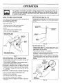
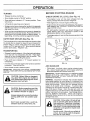
OPERATION
KNOW YOUR
TILLER
READ THiS OWNER'S MANUAL
AND SAFETY RULES BEFORE OPERATING YOUR T_LLER.
Compare the illustrations with your tiller to familiarize yourself with the location of various controls and adjustments.
manual for future reference.
Save this
RECOIL
STARTER
HANDLE
©
LEVELING
SHIELD
FIGURE to
MEETS
ANSl
SAFETY
REQUUREMENTS
Our tillers conform to the safety standards of the American National Standards institute,
THROTTLE CONTROL - is used to control engine speed,
DRIVE CONTROL BAR - is used to engage tiller,
DEPTH STAKE - controls depth at which tiller witi dig.
LEVELING SHIELD - protects small plants from being
buried.
SHIFT LEVER - is used to shift transmission gears.
SNDFT LEVER iNDICATOR- shows which gear the tiller is
currently in.
RECOIL STARTER HANDLE - is used to start the engine.
OUTER SIDE SHIELD - is adjustable for protecting small
plants from being buried,
CHOKE CONTROL - is used when starting a cold engine
SAFETY
DECAL
The decat shown below is located on the handle of your tiller.
9
OPERATION
The operation of any tiller can result In foreign objects thrown into the eyes, which can
result in severe eye damage. Always wear safety glasses or eye shields before starting
your tiller and while til|ing. We recommend wide vision safety mask for over the spectacles
or standard safety glasses.
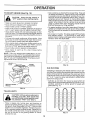
HOW TO USE YOUR TILLER
DEPTH
Know how to operate ali controls before adding fuel and
oil or attempting to start engine,
The depth stake can be raised or iowered to allow you more
versatile tilling and cultivating, or to more easily transport
,our tiller+
STOPPING
(See Fig. 11)
STAKE
(See Fig.
12)
TINES AND DRIVE . Release drive control bar to stop movement.
SHALLOWEST
, Move shift lever to "N" neutral position,
ENGINE -
c_
TILLING "_+-=_
• Move throttle control to "STOP" position.
"__'_'-_""_
¢
o Never use choke to stop engine,
®
®
DRIVE CONTROL BAR
"ENGAGED" POSiTiON
DEEPEST,..--TILLING
"="
TRANSPORT
POSITION
I
THROTTLE
CONTROL
DEPTH_
STAKE
LEVER
FIG. 12
HANDLE
TILLING
(See Fig. 13)
• Release depth stake pin, Pull the depth stake up for
increased tilling depth. Place depth stake pin in hole of
depth stake to lock in position.
. Place shift lever indicator in "T" position.
DRIVECONTROLBAR
"DISENGAGED"POSMON
• Hold the drive control bar against the handle to start tiliing
movement. Tines and wheels wi]l both turn.
• Move throttle controf to "FAST" position for deep tilling.
To cultivate, throttle control can be set at any desired
speed, depending on how fast or slow you wish to
cultivate,
FiG. 11
TfNE OPERATION
- WiTH
WHEEL
DRIVE
• Always release drive control bar before moving shift
lever into another position.
DEPTH
- Tine movement is achieved by moving shift lever to "T"
position and engaging drive control bar.
FORWARD
+WHEELS
ONLY/TINES
STOPPED
" Release drive control bar and move shift lever indicator
to "F" position. Engage drive control bar and tiller wiit
move forward,
REVERSE-WHEELS
ONLY/TINES
"LOCKED"
POSITION
STOPPED
• DO NOT STAND DIRECTLY BEHIND TELLER.
o Release the drive control bar.
• Move throttle control to "SLOW" position.
° Move shift lever indicator to "R" position.
OUTER
SIDE SHIELD
° Hold drive control bar against the handle to start tiller
movement,
10
FIG. 13
OPE
ATION
TURNING
BEFORE
* Release the drive control bar.
CHECK
o Move throttle control to "SLOW" position.
OiL LEVEL
(See Fig. 14)
, With engine level, remove engine oil filler plug.
. Lift handle to raise tines out of ground.
o Engine oil should be to point of overflowing. For approximate capacity see "PRODUCT SPECIFICATIONS" on
page 3 of this manual.
° Engage control bar and swing the handle in the opposite
direction you wish to turn, being careful to keep feet and
legs away from tine&
• For cold weather ope,,ration you should change oil for
easier starting (See O1L VISCOSITY CHART in the
Maintenance section of this manual).
, When you have completed your turn-around, release !he
drive control bar and lower handle. Place shift lever in T
position and move throttle control to desired speed. To
begin tilling, hold drive control bar against the handle.
SiDE SHIELDS
ENGINE
ENGINE
• The engine in your unit has been shipped, from the
factory, already filled with summer weight oil.
, Place shift lever indicator in 'F" forward position. Tines
wil( not turn.
OUTER
STARTING
• Tochangeengineoil,
manual.
seetheMaintenancesectioninthis
(See Fig. 13)
The front edges of the outer side shields are slotted so that
the shields can be raised for deep tilling and lowered for
shatiow titling to protect small plants from being buried.
Loosen nut "A" in slot and nut "B". Move shield to desired
position (both sides). Retighten nuts.
TRANSPORTING
• Release the depth stake pin. Move the depth stake down
to the top hole for transporting the tiller. Place depth
stake pin in hole of depth stake to lock in position. This
prevents tines from scuffing the ground.
OIL DRAIN
PLUG
• Place shift lever indicator in "F" forward position for
transporting.
OIL
FILLER
PLUG
FRG,14
• Hold the drive control bar against the handle to start tiller
movement. Tines will not turn.
ADD GASOUNE
o Move throttle control to desired speed.
IMPORTANT: PRACTICE THE ABOVE PROCEDURES
SEVERAL TIMES BEFORE FILUNG ENGINE WITH FUEL
AND OIL.
* Fill fuel tank. Use fresh, clean, regular unleaded gasoline. (Use of leaded gasoline will increase carbon and
lead oxide deposits and reduce valve life.)
iMPORTANT: WHEN OPERATING {N TEMPERATURES
BELOW 32°F (0°C), USE FRESH, CLEAN, WINTER
GRADE GASOLINE TO HELP INSURE GOOD COLD
WEATHER STARTING.
WARNING:
Experience indicates that alcohol blended
fuels (called gasohol or using ethanol or methanol) can
attract moisture which leads to separation and formation of
acids during storage. Acidic gas can damage the fuel
system of an engine whife in storage. To avoid engine
problems, the fuel system should be emptied before storage of 30 days or longer. Drain the gas tank, start the
engine and let it run until the rue1 lines and carburetor are
empty. Use fresh fuel next season. See Storage instructions for additional information.
Never use engine or
carburetor cleaner products in the fuel tank or permanent
damage may occur.
CAUTION; Before operating your tiller
for the first time, study tht[s section and
the "SAFETY RULES" on page 2.
Always release drive eontrot bar before
moving shift lever into another pos|=
tion.
Don't back yourself into a solid obstruction such as a tree, fence, ere.
11
CAUTION: Fill to within1/2 inch of fuel
tank to prevent _piils and to allow for
fuel expansion, {fgasoline is aceiden=
tally spilted, move machine away from
area of spil!, Avoid creating any source
of ignition until gasoline vapors have
disappeared.
Do not overfill Wipe off any spi_led oil
or rue!. Do not store, split or use gasoSine near an open flame°
OPERATION
TO START
ENGINE
(See Fig. 15)
CAUTION:
Keep the fine control in
"OFF" position when starting engine,
1
,
•
•
•
Make sure spark plug wire is properly connected.
Move shift tever indicator to "N" neutral position.
Place throttle control in "FAST" position.
Place choke control in "CHOKE" position if the engine is
cold. A warm engine may not require choking to start.
, Grasp starter handle with one hand and grasp the tiller
with other hand. Pull rope out slowly until engine reaches
start of compression cycle (rope will pull slightly harder at
this point).
• Pu!l rope with a rapid, continuous, full arm stroke. Keep
a firm grip on starter handle and let rope rewind slowly.
Do not let starter handle snap back against starter.
, Soil conditions are important for proper tilling. Tines will
not readily penetrate dry, hard soil which may contribute
to excessive bounce and difficult handling of your ti!ler.
Hard soil should be moistened before tilling; however,
extremely wet soil will "ball-up" or clump during tilling.
Wait until the soil is less wet in order to achieve the best
results. When tilling in the fall, remove vines and long
grass to prevent them from wrapping around the tine
shaft and slowing your tilling operation.
• For easier handling of your tiller, leave about 8 inches of
untilled soil between the first and second tilling passes.
The third pass will be between the first and second (See
Fig. 16).
, Do not lean on handle. This takes weight off the wheels
and reduces traction. To get through a really tough
section of sod or hard ground, apply upward pressure on
handle or lower the depth stake.
/
, When engine starts, slowly move choke control on engine halfway between CHOKE and "RUN" positions
and then to "RUN" position as engine warms up.
• Move throttle control to desired running position.
, Allow engine to warm up for a few minutes before
engaging tines.
NOTE: If at a high altitude (above 3000 feet) or in cold
temperatures (below 32°F), the carburetor fuel mixture
may need to be adjusted for best engine performance.
See "TO ADJUST CARBURETOR" in the Service and
Adjustments section of this manual.
PLUG
CHOKE
FiG. 16
CULTIVATING
Cultivating is destroying the weeds between rows to prevent them from robbing nourishment and moisture from the
plants. At the same time, breaking up the upper layer of soil
crust will help retain moisture in the soil. Best digging depth
is 1" to 3". Lower the outer side shields to protect small
plants from being buried.
\11
, Cultivate up and down the rows at a speed which will
allow tines to uproot weeds and leave the ground in rough
RECOIL STARTER
HANDLE
grassC°nditi°n'(seePr°m°tingFig.
17), no further
growth
FIG, 15
TILLING
I
i
I
HINTS
dh
CAUTION: Until you are accustomed to
handling your tiller, start actual field
use with throttle in s!ow position (mid-
''a.d
"IDLE").
OI
U
, Tilling is digging into, turning over, and breaking up
packed soit before planting, Loose, unpacked soil helps
root growth. Best tilling depth is 4" to 6". A tiller will also
clear the soil of unwanted vegetation. The decomposition
of this vegetable matter enriches the soil. Depending on
the climate (rainfall and wind), it may be adwsable to tilt
the soil at the end of the growing season to further
condition the soil,
f\
L-J
,J
FiG. 17
I2
f\
of weeds
and
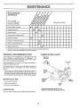
MAINTENANCE
MAINTENANCE
SCHEDULE
FILL tN DATES
AS YOU COMPLETE
REGULAR SERVICE
SERVICE
DATES
Check Engine Oil Level
Change Engine Oil
Oil Pivot Points
inspect Spark Attester Muffler
inspect Air Screen
Replace Air CIeaner Cartridge
Clean Engine Cylinder Fins
Replace Spark Plug
- Change more often when operating under a heavy load or in high ambient temperatures.
2. Service mote often when operating in dirty or dusty conditions,
GENERAL
RECOMMENDATIONS
LUBRICATION
The warranty on this unit does not cover items that have
been subjected to operator abuse or negligence.
To
receive full value from the warranty, operator must maintain unit as instructed in this manual,
CHART
*THROTTLE
CONTROL
Some adjustments will need to be made periodiealty to
properly maintain your unit.
All adjustments in the Service and Adjustments section of
this manual should be checked at least once each
season.
, Once a year you should replace the spark plug, clean or
replace air filter, and check tines and belts for wear. A
new spark plug and clean air filter assure proper air-fuel
mixture and help your engine run better and last longer,
BEFORE
EACH
\
USE
* _DLER
BRACKET
• Check engine oil level.
, Check tine operation.
• Check for loose fasteners.
* WHEEL
HUB
* SAE 30 OR 10W30 MOTOR OIL AP! _ SG
REFER TO ENGINE MAINTENANCE SECTZON
LUBRICATfON
Keep unitwell_ubdoated(See "LUBRICATION CHART").
13
NTENANCE
Disconnect spark plug wire before performing any maintenance
to prevent accidental starting of engine.
(except carburetor adjustment)
Prevent firesl Keep the engine free of grass, leaves, spilled oil, or fuel. Remove fuel from tank
before tipping unit for maintenance.
Clean muffler area of all grass, dirt and debris.
Do not touch hot muffler or cylinder fins as contact may cause burns.
ENGINE
AIR CLEANER
LUBRICATION
Replace air cleaner cartridge every twenty-five hours, more
often if engine is used in very dusty conditions,
Change the oil after the first two hours of operation and
every 25 hours thereafter or at least once a year if the tiller
is not used for 25 hours in one year.
• Loosen air cleaner screws, one on each side of cover,
Check the crankcase oil tevel before starting the engine
and after each five (5) hours of continuous use. Add SAE
30W motor oil or equivalent. Tighten oil filler plug securely
each time you ch eck the oil level. SAE 5W-30 motor oil may
be used to make starting easier in areas where temperature
is consistently 32 ° F or lower.
. Carefully remove air cleaner cartridge. Be careful. Do not
allo w dirt or debris to fall into carburetor.
. Install new air cleaner cartridge. Clean and replace
cover. Tighten screws securely.
o Remove air cleaner cover,
NOTE: Do not attempt to clean or oil the paper cartridge.
TO CHANGE ENGlNE OIL (See Figs. 18 and 19) Determine temperature range expected before oil change,
All oii must meet API service classification SG.
, Be sure tiller is on level surface.
• Oit will drain more freety when warm.
• Catch oil in a suitable container.
• Remove drain plug.
• Tip tiller forward to drain oil.
• After oil has drained compfeteiy, replace oil drain plug
and tighten securely.
• Remove oil filler plug. Be careful not to allow dirt to enter
the engine.
• Refill engine with oil,
RECOMMENDED
(See Fig. 20)
AIR
CLEANER
SCREW
COVER
AIR CLEANER
SAE VISCOSITY GRADES
FiG. 20
.20°
0o
32 °
60°
80°
I00 °
COOLING
FIG. 18
SYSTEM
(See Fig. 21)
Your engine is air cooled, For proper engine performance
and tong life keep your engine clean.
Clean air screen frequently using a stiff bristled brush.
• Remove blower housing and clean as necessary.
• Keep cylinder fins free of dirt and chaff.
CYLINDER
FINS
MUFFLER
BLOWER
AIR SCREEN
FiG, 19
F_G. 21
!4
NTENANCE
MUFFLER
TRANSMISSION
Do not operate tiller without muffler, Do not tamper with
exhaust system, Damaged mufflers or spark attesters
could create a fire hazard, inspect periodically and replace if necessary. If your engine is equipped with a spark
arrestor screen assembly, remove every 50 hours for
cleaning and inspection. Replace if damaged.
Your transmission is seated and will only require lubrication
if serviced.
SPARK
CLEANING
• Clean engine, wheels, finish, etc, of alt foreign matter.
- Keep finished surfaces and wheels free of all gasoline,
oil, etc.
. Protect painted surfaces with automotive type wax.
We do not recommend using a garden hose to dean your
unit unless the muffler, air filter and carburetor are covered
to keep water out. Water inengine can result in a shortened
engine life.
PLUG
Replace spark plugs at the beginning of each tilling season or after every 50 hours of use, whichever comes first.
Spark plug type and gap setting is shown in "PRODUCT
SPECIFICAT!ONS" on page 3 of this manual.
SERVICE AN
CAUTION:
ADJUSTMENTS
contact
Disconnect
with spark
pEug.plug wires from spark plug and place wire where it cannot come into
TILLER
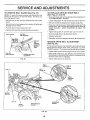
TO ADJUST
TIRE CARE
HANDLE
HEIGHT
(See Fig. 22)
Select hand{e height best suited for your tilting conditions,
Handte height will be different when tiller digs into soil.
, First loosen handle lock ]ever,
• Handle can be positioned at different settings between
"HIGH" and "LOW" positions,
• Maintain 20 pounds of tire pressure, If tire pressures are
not equal, titler will pull to one side,
• Retighten handle lock Iever securely after adjusting,
° Keep tires free of gasoline
rubber,
TO REMOVE
_HANDLE(HIGH
_:_PosmoN)
WHEEL
or oil which can damage
(See Fig, 23)
• P{ace blocks under transmission to keep tilter from tipping.
• Remove outer side shield (See Fig. 10).
HANDLE
LOCK
LEVER
° Remove hairpin ctip and clevis pin from wheel,
• Remove wheel and tire.
• Repair tire and reassemble.
HANDLE (LOW
POSITION}
FiG, 22
FIG. 23
15
SERVICEAN
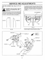
TO REMOVE
BELT GUARD
ADJUSTI
ENTS
TO REPLACE GROUND
(See Figs. 24 and 25)
(See Fig. 24)
NOTE: For ease of removal, remove outer side shield, and
hairpin clip and clevis pin from left wheel. Pull wheel out
from tiller about 1 inch.
DRIVE
BELT
, Move left wheel and remove belt guard as described in
"TO REMOVE BELT GUARD".
, Remove two (2) cap nuts and washers from side of belt
guard.
Loosen belt guides"A" and "B" and also nuts "C" and "D".
Remove old belt by slipping from engine pufley first.
o Remove hex nut and washer from bottom of be_t guard
(located behind wheel),
Place new belt in groove of transmission pulley and into
engine pulley. BELT MUST BE IN GROOVE ON TOP OF
iDLER PULLEY.
NOTE POSITION
OF BELT TO
GUIDES.
o Pult belt guard out and away from unit,
• Replace belt guard by reversing above procedure,
, Tighten belt guides "A" and "B" and nuts "C" and "D".
BELTGUARD
• Check belt adjustment as described below.
CAP NUT
AND WASHER
• Replace belt guard.
• Repositien wheel and replace clevis pin and hafrpin clip.
GROUND
AND
WASHER
HEX NUT
(LOCATED
BEHIND
TIRE)
BELT
ADJUSTMENT
(See Fig. 25)
For proper belt tension, the extension spring should have
about 5/8 inch stretch when drive control bar is in "ENGAGED" position. This tension can be attained as follows:
/
CAP NUT
AND WASHER
DRIVE
• Loosen cable clip screw securing the drive control cable.
, Slide cable forward for less tension and rearward for
more tension until about 5/8 inch stretch is obtained while
the drive control bar is engaged.
HAIRPIN CL|P AND
CLEVIS PIN
FIG, 24
• Tighten cable clip screw securely.
BELT
GUIDE "A'
CABLE
CLIP
CREW
BELT
GUIDE "B"
NUT "C"
OL
LESS
TENSION
ENGINE
PULLEY
J
NUT '_D"
IDLER
PULLEY
EXTENSION
SPRING
TRANSMISSION
PULLEY
FIG. 25
16
SERVICE AN
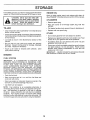
- TINE REPLACEMENT
(See Figs.
ADJUSTMENTS
26, 27 and
* To maintain the superb tilling performance of this machine the tines should be checked for sharpness, wear,
and bending, particufarfy the tines which are next to the
transmission. If the gap between the tines exceeds 3-1/
2 inches, they should be replaced or straightened as
necessary.
28)
ther protection
dling tines.
when han____.,=_
A badly worn tine causes your tiller to work harder and dig
more shallow. Most important, worn tines cannot chop and
shred organic matter as effectively nor bury it as deeply as
good tines. A tine this worn needs to be replaced.
TINE TRANSMISSION
v
NEW TINE
WORN TINE
3-1/2"
MAX
FIG, 27
+ Newtines should be assembled as shown below. Sharpened tine edges will rotate rearward from above.
FIG. 26
SHARP
EDGE
[
HAIRPIN CLIP
TINE
ROTATION
i COUNTER
L
.HAIRPIN
SHARP
EDGE
__
CLEVIS PIN
SHARP EDGE
SHARP
EDGE
CLEVIS PIN
SHARP EDGE
RG. 28
17
CLIP
SHARPEDGE
SERVICE AN
ADJUSTM
NTS
ENGINE
IDLE RPM ADJUSTMENT
TO ADJUST
• To adjust idle
clockwise and
speed adjusting
throttle linkage.
ACCELERATfQN
THROTTLE
CONTROL
CABLE
(See Fig. 29)
• Loosen cable clamp screw to allow cable to move,
, Move throttle control lever on upper handle to "FAST"
position.
RPM, rotate throttle linkage counterhold against stop while adjusting idle
screw to obtain 1750 RPM. Release
TEST -
• Move throttle control lever from "SLOW" to "FAST"
position. If engine hesitates or dies, turn needle valve
out (counterclockwise) 1/8 turn. Repeat test and continue to adjust, if necessary, until engine accelerates
smoothly.
•Puti throttle cable out until engine betlcrank is back as
far as it will go,
• Hold cable in this position and tighten clamp screw
securely.
High speed stop is factory adjusted. Do not adjust damage may result.
IMPORTANT:
NEVER TAMPER WITH THE ENGINE
GOVERNOR, WHICH iS FACTORY SET FOR PROPER
ENGINE SPEED, OVERSPEEDING THE ENGINE ABOVE
THE FACTORY
HIGH SPEED SETTING
CAN BE
DANGEROUS, tF YOU THINKTHE ENGINE-GOVERNED
HIGH SPEED NEEDS ADJUSTING, CONTACT YOUR
NEARESTAUTHORJZED SERVICE CENTER, WHICH HAS
PROPER EQUIPMENT AND EXPERIENCE TO MAKE ANY
NECESSARY ADJUSTMENTS,
CLAMP SCREW
THROTTLE
CABLE
THROTTLESTOP
THROTTLE
LINKAGE
BELLCRANK
F_G. 29
TO ADJUST
CARBURETOR
(See Fig. 30)
The carburetor has been preset at the factory and adjustment should not be necessary_ However, minor adj{_stments may be required to compensate for differences
in fuel, temperature, altitude or load. If the carburetor
does need adjustment, proceed as follows,
IDLE SPEED
ADJUSTING
SCREW
In general, turning the needle valve in (clockwise) decreases the supply of fuel to the engine giving a leaner
fuel/air mixture, Turning the needle valve out (counterclockwise)
increases the supply of fuel to the engine
giving a richer fuel/air mixture.
IMPORTANT:
DAMAGE TO THE NEEDLES AND THE
SEATS tN CARBURETOR MAY RESULT iF SCREWS
ARE TURNED IN TOO TIGHT.
NEEDLE
VALVE
FIG. 30
PRELIMINARY SETTING ° Air cleaner assembly must be assembled to the carburetor when making carburetor adjustments.
. Be sure the throttle controt cable is adjusted properly
(see above).
• With engine off turn needle valve in (clockwise) closing
it finger tight and then turn out (counterclockwise) 1-1/
2 turns.
FINAL SETTING ° Start engine and altow to warm for five minutes. Make
final adjustments with engine running and gear shift
control lever in "NEUTRAL" position.
• With throttle control lever in "SLOW" position, turn
needle valve in (clockwise) until engine begins to die
then turn out (counterclockwise) until engine runs rough.
Turn valve to a point midway between those two positions.
!8
STORAGE
Im mediately prepare your tiller for storage at the end of the
season or if the unit will not be used for 30 days or more,
ENGINE
OIL
Drain oil (with engine warm) and replace with clean oil.
(See "ENGINE" in the Maintenance section of this manual).
CAUTION: Never store the tiller with
gasoline in the tank inside a building
where fumes may reach an open flame
or spark. Allow the engine to cool
before storing in any enclosure,
CYLINDERS
• Remove spark plug.
• Pour one ounce of oil through
cylinder.
spark plug hole into
TILLER
• Pull starter handle stowly several times to distribute oil.
• Clean entire tiller (See "CLEANING" in the Maintenance
section of this manual).
• Replace with new spark plug.
OTHER
, Inspect and replace belts, if necessary (See bett replacement instructions in the Service and Adjustments section
of this manual).
• Lubricate as shown in the Maintenance section of this
manual.
• Do not store gasoline from one season to another.
• Replace your gasoline can if your can starts to rust. Rust
and/or dirt in your gasoline will cause problems,
• If possible, store your unit indoors and cover it to give
protection from dust and dirt,
• Be sure that afi nuts, bolts and screws are securely
fastened. Inspect moving parts for damage, breakage
and wear. Replace if necessary.
, Touch up all rusted or chipped paint surfaces;
lightly before painting.
• Cover your unit with a suitable protective cover that does
not retain moisture, Do not use plastic. Plastic cannot
breathe which allows condensation to form and will
cause your unit to rust,
IMPORTANT:
NEVER COVER TILLER WHILE ENGINE
AND EXHAUST AREAS ARE STILL WARM.
sand
ENGINE
FUEL SYSTEM
IMPORTANT:
IT IS IMPORTANT TO PREVENT GUM
DEPOSITS FROM FORMING IN ESSENTIAL FUEL
SYSTEM PARTS SUCH AS THE CARBURETOR, FUEL
FILTER, FUEL HOSE, OR TANK DURING STORAGE.
ALSO, EXPERIENCE
iNDICATES THAT ALCOHOL
BLENDED FUELS (CALLED GASOHOL OR USING
ETHANOL OR METHANOL) CAN ATTRACT MOISTURE
WHICH LEADS TO SEPARATION AND FORMATION OF
ACIDS DURING STORAGE. ACIDIC GAS CAN DAMAGE
THE FUEL SYSTEM OFAN ENGINE WHILE IN STORAGE,
• Drain the fuel tank.
• Start the engine and let it run until the fuel lines and
carburetor are empty.
, Never use engine or carburetor cleaner products in the
fuel tank or permanent damage may occur.
o Use fresh fuel next season,
NOTE: Fuel stabilizer is an acceptable alternative in
minimizing the formation of fuel gum deposits during storage, Add stabilizer to gasoline in fuel tank or storage
container. Always follow the mix ratio found on stabilizer
container. Run engine at least 10 minutes after adding
stabilizer to allow the stabilizer to reach the carburetor. Do
not drain the gas tank and carburetor if using fuel stabilizer,
19
d
L.....
TROUBLESHOOTING
,lu:l
i,ll
PROBLEM:
Probable Cause ,,_- Possible Remedy
WiLL
NOT START OR HARD TO START
Dirty Air Cleaner
Loose Spark Plug Wire r_
Spark Plug dirty or improper gap {,r
Water in gasoline or old fuel ,_
Fill tank with gasoline
Place Choke Control in "CHOKE" position
Place Throttle Control in "FAST" position
Move Choke control to "Run" position, place Throttle Control in
"FAST" position and pull Starter several times to clear out gas
Remove and replace
Make sure Spark Plug Wire is seated properly on Spark Plug
Replace Spark Plug and adjust gap
Drain Fuel Tank and Carburetor, use fresh fuel and replace Spark
Improper Carburetor adjustment _
Clogged Fuel Tank _._
Plug
Make necessary adjustments
Remove and clean
No gasoline in Fuel Tank
Choke not set properly _
Throttle Control not set properly
Choked improperly, flooded Engine,_
ENGINE
MISSES
Engine overloaded
Partially plugged Air Cleaner
Dirty Air Screen
Spark Plug dirty, improper gap or wrong type
Oil in gasoline
Improper Carburetor adjustment
Clogged Fuel Tank
Poor compression
_
r,r
<___o__
_
OR LACKS
POWER
Set Depth Stake and Wheels for shallower tilling
Remove and inspect; replace if dirty
Clean Air Screen
Replace Spark Plug and adjust gap
Drain and refill Gas Tank and Carburetor
Make necessary adjustments
Remove and clean
Major Engine overhaul
ENGBNE OVERHEATS
Low oil levet or dirty oil
Dirty Air Screen
Dirty Engine
Partially Plugged Muffler
Improper Carburetor adjustment
EXCESSIVE
_e
_
_
_,r
Add or change oil
Clean Air Screen
Clean Cylinder Fins, Air Screen and Muffler area
Remove and clean Muffler
Make necessary adjustments
BOUNCE
Wheels and Depth Stake incorrectly adjusted _
Ground too dry and hard ,_
AND DiFFiCULT
Adjust Wheels and Depth Stake
Moisten ground or wait for more favorable soil conditions
SOiL BALLS
Ground too wet,_
ENGINE
HANDUNG
UP OR CLUMPS
Wait for more favorable soil conditions
RUNS WELL BUT TroLLER WON'T
MOVE
Drive Control Bar not engaged,_Engage Drive Control
V-Belt not correctly adjusted_
Check V-Belt
V-Belt off of pulleys _,_- Check V-Belt
ENGINE
RUNS WELL
Tilling too deep _Throttle Control not properly adjusted _
Carburetor not adjusted properly_
BUT LABORS
WHEN
TILLING
Adjust Depth Stake
Check Throttle Control setting
Check Carburetor adjustment
2O
REPAIR PARTS
5 HP 17" CRT TILLER
- - MODEL
NUMBER
917.299691
HANDLE ASSEMBLY
2
1
11
13
\
16
\
t7
'\
\
\
KEY
NO.
PART
NO,
1
2
3
4
5
6
7
t10707X
110674X
110673X
t27254X
6712J
110641X
STD511005
8
9
126948X
STD533125
10
11
12
13
14
15
16
t7
18
I9
t09313X
t10741X
110646X
STD624003
81328
110702X
STD541437
109229X
STD533710
19131611
DESCRIPTION
Cap, Sleeve
Grip, Handle
Grommet, Handle
Bar, Drive Control Assembly
Cap, Vinyt
Bushing, Split
*Screw, Mach. Pan Head. C.R.
#10-24 x 1/2
Panei, Control
* Bolt, Carriage
5/t6-18 UNC x 2-3/8 Gr. 5
Grommet, Rubber
Handle, Shift
Handle, Grip
* Clip, Hairpin
Bolt, Shoulder
Rod, Shift
* Nut, Centerlock 3/8-16
Lock, Handle
*Bolt, Carriage 3/8-16 x 1 Gr. 5
Washer 13/32xl
xll
Ga.
KEY
NO.
PART
NO.
20
21
22
23
109228X
121213X
121145X
86777
24
25
26
27
28
29
30
-----
9484R
73970500
110675X
STD541025
STD551125
STD541462
127012X
127812
120431X
121859X
127795
DESCRIPTION
Lever, Lock, Handle
Handle, Assemble
Clip, Plastic, Cable
Screw, Hex, Washer Hd, Slotted
#10-24 x t/2
Clip
Locknut, Hex, Flange
Clutch, Cabfe
* Nut, Hex t/4-20
*Washer, Lock 1/4
* Nut, Keps #10-24
Throttle, Control
Manual, OwneCs
Decal, Hand Placement
Decal, Caution-Clutch
Decal, Control Panel
* STANDARD HARDWARE--PURCHASE
LOCALLY
NOTE: All component dimensions given in U.S. inches,
1 inch = 25.4 mm
21
REPAIR PARTS
5 HP 17" CRT TILLER
- - MODEL NUMBER
917.299691
MAINFRAME_ LEFT SIDE
13
12
40
13
19
\
22
16
18
33
123
KEY
NO.
PART
NO.
1
2
3
4
5
6
7
8
10
STD541431
STD551137
STD541037
74930576
STD571810
110111X
STD532505
8700J
86777
11
12
13
14
15
16
17
18
!9
20
21
22
23
25
9484R
STD551125
STD541025
STD503103
120938X
STD55103t
100473M
STD541031
110651X
2649M
110653X
110652X
104214X
5015J
124366X
795R
126875X
STD624003
102148X417
126791X
26
27
28
29
DESCRIPTEON
*Nut, Keps 5/16-18
* Washer, Lock 3/8
*Nut, Hex 3/8-16
Bolt, Hex 5/16-18 x 4-3/4
* Pin, Roll
Lever, Shift
* Bolt, Carriage 1/4-20 x 1/2 Gr. 5
Plate, Shift Indicator
Screw, Hex, Washer Head, Slotted
#10-24 x 1/2
Clip
*Washer, Lock 1/4
* Nut, Hex 1/4-20
* Screw, Set, Hex 5/16-18 x 3/8
Spacer, Split 0.327 x 0.42 x 2.68
*Washer 11/32 x 11/16 x 16 Ga.
Sheave, Transmission
* Nut, Hex 5/16-t8
Spacer, Split 0.327 x 0.42 x 1.75
Key, Square 3/16 x 1-1/8
Guard, Pinch Point
Spacer, Split 0.327 x 0.42 x 2.09
Nut, Cap 5/t6-18
Tire
Rim
Tire Valve
Rivet, Drifled
* Clip, Hairpin
Guard, Belt
Belt, V
16
23
KEY
NO.
3O
31
32
33
34
35
36
37
38
39
40
PART
NO.
104679X
12000032
102384X
t05611X
102t41X
STD523710
102383X
74760524
102331X
9177R
126788X
102180X
127806
DESCRIPTION
Pulley, Idler
Ring, Klip
Bolt, Hex 5/16-16 x 12
Bracket, Idler
Shaft, Idler Arm
* Bolt, Hex 3/8-16 x 1
Counterweight, L. H.
Bolt, Hex 5/16-18 x 1-t/2
Bracket, Reinforcement, L. H.
Sheave, Engine
Bracket, Guard Belt
Decal, Shift Indicator
Decal (Belt Guard)
* STANDARD HARDWARE--PURCHASE
LOCALLY
NOTE; AH component dimensions given in U.S. inches.
1 inch = 25.4 mm
22
:REPAIR PARTS
5 HP 17" CRT TILLER
MAINFRAME,
-- MODEL NUMBER
917.299691
RIGHT SiDE
9
/
/
i
7
KEY
NO.
l
2
3
4
5
6
7
8
PART
NO.
STD541431
102332X
74760524
102173X
STD551137
STD541037
STD624003
126875X
DESCRIPTION
*Nut, Keps 5/16-18
Bracket, Reinforcment
Bolt, Hex 5/16-18 x 1-1/2
Counterweight, R+H.
*Washer, Lock 3/8
*Nut, He× 3/8-16
*Clip, Hairpin
Rivet, DriNed
KEY
NO.
PART
NO.
9
5015J
124366X
795R
123081X
127520
110719X
.
+
+ .
* STANDARD
DESCRiPTiON
Tire
Rim
Valve,
Decal,
Decal,
Decal,
Tire
Engine
U.S.A.
Operation and Lubrication
HARDWARE--PURCHASE
LOCALLY
NOTE: All component dimensions given in U+SJnches,
linch = 25,4 mm
23
35
o_
44"
KEY
_,7_o
2
PART
NO,
121147X
3
4
5
8
7
8
9
t0
II
12
13
14
15
16
17
I8
t9
20
t06211X
5020j
t370H
t02113X
t02110X
4895H
t02136X
7392M
100371K
106160X
102107X
8353J
12000039
102109X
104159X
4358J
12000040
102114X
21
22
23
24
25
102115X
6803J
102111X
STD551143
STD551143
°51
DESCRiPTiON
Transmission Assembly
_ncludes Key Noso 2-52)
earcase, L.H. w/Bearing
GlnCludes Key No. 4)
asket, Gearcase
Bearing, Needle
Washer, Thrust 5/8 x 1.10 x 1/32
Pinion, Input
Shaft, input
Bearing, Needle
Washer, Seal
Ball, Steel
Spring, Shift, Fork
O-Ring
Arm,. Shift
Fork, Shift
Ring, KHp
Shaft, Shift
Spacer, Spilt
Washer
Ring, Ktip
Gear, Assembly, Reverse Idler
(Includes Key Nos. 2t and 22)
Gear, Reverse Idler
Bearing, Needle
Shaft, Reverse Idler
*Washer, Lock 7/16
* Nut, Hex 7/1(}-20
KEY
NO,
PART
NO.
26
27
28
29
30
31
32
33
34
35
36
102128X
102t00X
106390X
102134X
124458X
t02106X
106388X
102121X
102112X
102101X
124358X
37
38
39
40
41
42
43
44
45
46
47
48
4422J
124359X
105345X
105346X
8358J
4220R
106146X
9672R
102!44X
9676R
9674R
121745X
49
50
51
52
53
106144X
124361X
17580408
STD54103t
6066J
DESCRIPTION
O-Ring
Bearing, Shaft, Ground Drive
Spacer 0,765 x 1.125 x 1o23
Chain #35-50 Pitch
Ground Shaft Assembly
Bearing, Shaft, Ground Drive
Spacer 0.70 x 1.00 x 1,t50
Sprocket and GearAssembly
Shaft, Reduction (2nd)
Screw, Whiz, Lock 5/16-18x3-!/2
Sprocket Assembly w/Bearing
(Includes Key Nos. 37 and 38)
Bearing, Needle
Sprocket, Tine
Gear, Cluster, Red 1st & 2rid
Gear, Reverse
Shaft, Reduction (1st)
Washer, Thrust
Spacer 1.01 x 1.75 x 0.760
Cup, Formed
Ring, Spiral
Seal, Ring, Rubber
Seal, Oil
Gearcase, R.H. w/Bearing
(Includes Key No. 8)
Shaft, Tine
Chain, Roller #50-50 Pitch
Screw 1/4-20 x 1/2
* Nut, Hex 5/16-18
Grease, Plastiiube #1
* STANDARD HARDWARE--PURCHASE
24
LOCALLY
NOTE: All component dimensions given in U.S. inches.
1 inch = 25.4 mm
REPAIR PARTS
5 HP
17" CRT TILLER
= - MODEL
NUMBER
917.299691
TINE SHIELD
13
17
24
KEY
NO,
1
2
3
4
5
6
7
8
9
10
11
t2
13
14
15
t6
t7
t8
PART
NO.
DESCRIPTION
KEY
NO,
98000129
Nut, Flange 5/t6-18
104086X417
Shield, Side, Outer L. H.
t24309X417
Shie!d, Side
8393J
Pin, Stake, Depth
12000036
Ring, Klip
STD533107
* Bolt, Carriage 5/16-18 x 3/4 Gr 5
8394J
Spring
109230X
Spring, Stake, Depth
t24289X417
Shield, Tine
STD532512
*Bolt, Carriage 1/4-20 x 1-1/4 Gr. 5
STD541031
*Nut, Hex 5/16-18
STD551131
*Washer, Lock 5/16
72110508
Bolt, Carriage 5/16-18 x 1
1243l IX
Bracket, Shield, Tine
104101X417
Shield, Side, Outer R.H.
STD541025 *Nut, Hex 1/4-20
STD551t25
*Washer, Lock 1/4
73970500
Locknut, Hex, Flange
PART
NO.
19 10270tX
20 STD541037
21 102156X
22 74930632
23 4440J
24 STD532505
25 6712J
26 109227X
27 102695X417
29 120588X
30 8392J
31 72110510
- - 120075X
- _ 127807
DESCRIPTION
Grip
*Nut, Hex 3/8-16
Stake, Depth
Bolt, Hex 3/8-16 x 2
Hinge
* Bolt, Carriage 1/4-20 x 1/2 Gr. 5
Cap, Vinyl
Pad, idler
Shield, Leveling
Pin, Hinge
Bracket, Latch
Bolt, Carriage 5/16-t8x!-1/4
Deca!, Warning (Leveling Shield)
Decal, Tine Shield
* STANDARD HARDWARE--PURCHASE
LOCALLY
NOTE: All component dimensions given in U.S. inches.
1 inch = 25.4 mm
25
REPAIR PARTS
5 HP
17" CRT TILLER
- - MODEL
NUMBER
917.299691
TINES
1
1
9
11
10
9
KEY
NO.
1
2
3
4
5
6
PART
NO.
4459J
74610616
STD551137
73610600
4929H
I02380X
KEY
NO,
DESCRIPTION
7
8
9
10
11
Tine, L. H. Outer
Bolt, Hex 3/8-24 x 1
* Washer, Lock 3/8
Nut, Hex 3/8-24
Pin, Clevis
Assembly, Hub apd Plate,, L. H,
PART
NO,
6554J
6555J
4460J
STD624008
102382X
DESCRIPTION
Tine, L. H. Inner
Tine, R, H. Inner
Tine, R, H. Outer
*Clip, Hairpin
Assembly, Hub and Plate, R.H.
* STANDARD HARDWARE--PURCHASE
NOTE:
26
LOCALLY
All component dimensions given in U,S. inches,
1 inch = 25.4 mm
REPAIR PARTS
ENGINE
5 HP 17" CRT TILLER -- MODEL NUMBER 917.299691
, BRIGGS & STRATTON-MODEL NUMBER
130202, TYPE NUMBER
ENGINE, RIGHT SIDE
3129-01
16
12
/
17
19 20
..q
/
I
'
!
1
5
2 3
I0
7
8
I
!
]
32
!
31
33
KEY
NO.
PART
NO,
1
390463
2
3
4
5
230228
66728
66884
299431
DESCRIPTION
6 92987
7 490179
8 295871
9 94128
I0
222598
11490817
12 490169
13 93158
14 93490
t5
221923
16 399671
Starter Assembly, Rewind (Inc. Key
No's 2-9)
Pin, Starter Grip
Grip, Starter Rope (Inc. Key No. 2)
Rope, Starter 63" Long
Housing, Starter (Inc. Key No's 8
and 9)
Nut, Hex
Spring, Starter
Pulley, Starter 0nc. Key No. 4)
Screw, Starter Housing Mounting
Anchor, Spring
Spacer
Housing, Blower
Screw, Blower Housing Mounting
Screw, Sem
Screen, Starter Pulley
Clutch Assembly 0nc. Key No's 17-
17
Washer, Clutch Retainer
KEY
NO.
PART
NO.
18
19
20
21
22
23
24
25
63770
298799
394897
220865
297229
93414
223886
397358
26
27
28
221798
398808
395990
29
30
3I
32
33
299819
297565
222443
93705
222698
DESCRIPTION
Ball, Clutch
Ratchet
Housing, Starter Clutch
Washer, Spring
Flywheel, Magneto
Screw, Armature Mtg. Sere
Guide, Air
Armature Assembly (inc. Key No.
26)
Cable, Terminal Ignition
Wire, Ground
Cylinder Assembly (Inc, Key No.
29)
Seal, Oil
* Bushing, Cylinder (Inc. Key No. 29)
Guard, Flywheel
Screw, Flywheel Guard
Key, Flywheel
2O)
394506
* REQUIRES SPECIAL TOOLS TO INSTALL
27
REPAIR PARTS
ENGINE
5 HP 17" CRT TILLER -= MODEL NUMBER 917.29969t
= BRiGGS & STRATTON -- MODEL NUMBER
130202, TYPE NUMBER
ENGINE, REAR
3129-01
2
3
4
5
10'
7 _
55
48
49
50
KEY
NO.
1
2
3
4
5
6
7
PART
NO.
490073
223765
399959
94018
490074
271935
492611
8
9
223793
93499
10
11
12
13
I4
15
t6
t7
t8
19
20
93527
260575
490048
271853
398970
26227O
271936
280720
231520
231533
491177
21
22
23
24
25
27
28
29
30
270382
221839
26336
223789
391813
220352
221377
262328
270026
DESCRIPTION
Screw, Cover Mounting
Cover, Air Cleaner
Filter, Air
Screw, Air Cleaner
Base, Air Cleaner
Gasket, Air Cleaner Mtg,
Carburetor Assembly (Inc. Key
No's 8 thru 33)
Throttle, Carburetor
Screw, Throttle Valve to Shaft
Sem
Screw, Machine
Spring, Throttle Adjustment
Shaft and Lever, Throttle
Washer, Throttle Shaft (Foam)
Seal, Throttle Shaft
Link, Throttle
Gasket, Carburetor Mtg. (2)
Crank, Bell
Screw, Shoulder
Valve, Needle
Valve, Group, Choke (Inc. Key
No's 21 and 22)
Washer, Choke Shaft (Felt)
Washer, Choke Shaft
Spring, Needle Va]ve
Plug, Welch
Fuel Pipe and Cfip
Plug, Welch
Cap, Spring
Spring, Fuel Pump Diaphragm
Diaphragm
KEY
NO,
31
32
33
34
35
36
37
38
39
40
41
42
PART
NO,
210959
93265
93141
93543
490589
223813
490507
262279
220982
93357
280715
490649
43
44
45
46
47
48
262359
262470
93572
262282
491577
93491
49
50
51
52
53
54
222962
223455
396847
94409
280321
490554
55
56
57
58
490075
271928
223785
94094
DESCRIPTION
Cover, Diaphragm
Pin, Diaphragm Cover
Screw, Diaphragm Cover
Screw, FiL Hd.
Screw and Collar
Crank, Bell
Retainer, Rod
Rod, Control
Washer
Screw, Hex Hal.
Knob, Control
Control Panel (lnc, Key No's 37,
41, and 51)
Link, Choke
Link, Throttle
Screw
Spring, Governor
Control, Throttle
Rivet, Governor Control Lever
Mtg.
Bushing, Governor Lever (Flat)
Lever, Governor Control
Switch, Stop
Screw, Tank Bracket Mtg. Sem
Gear Rack, Governor
Tank, Fuel (tnc, Key No's 48,
49, 50, and 55)
Cap, Fuel Tank
Gasket, Fuel Tank Mounting
Clamp, Breather Tube
Screw, Fuel Tank Mtg.. Sem
** iNCLUDED IN GASKET SET NO, 397145
28
REPAIR PARTS
ENGINE
5 HP 17" CRT TILLER -- MODEL NUMBER 917.299691
- BRIGGS & STRATTON
-- MODEL NUMBER
130202, TYPE NUMBER
ENGINE, LEFT SIDE
\
i,r-..,,
"y]
10
KEY
NO,
PART
NO.
1
2
3
90832
93656
297602
4
5
6
7
8
9
t0
11
294606
297603
66768
270080
93490
221511
93032
91249
DESCRIPTION
Washer, Lock
Stud
Cover Assembly, Crankcase (Inc.
Key No.'s 5,6, and 7)
Seat, Oil
* Bushing, Crankcase Cover
Plug, Oil Filler
** Gasket, Crankcase .015' thick
Screw, Cylinder Shield Mtg. Sere
Shield, Cylinder
Screw, Crankcase Cover Mt.g.
Plug, Pipe 1/4" Std. (Square Head)
* REQUIRES SPECIAL TOOLS TO iNSTALL
** INCLUDED IN GASKET SET NO. 397145
29
3129-01
REPAIR PARTS
ENGINE
5 HP 17" CRT TILLER -- MODEL NUMBER 917.299691
- BRIGGS & STRATTON -- MODEL NUMBER
130202, TYPE NUMBER
3129-0t
ENGINE, INTERNAL PARTS
5
I
-_17
19
20
18
25
30
4O
!
39
36
j
L_
34
35
30
33
31
REPAIR PARTS
ENGINE
5 HP 17" CRT TILLER -- MODEL NUMBER 917.299691
- BRIGGS & STRATTON o- MODEL NUMBER
130202, TYPE NUMBER
3129-01
ENGINE, iNTERNAL PARTS
KEY
NO,
PART
NO.
1
2
3
2t 1542
94221
93369
4
5
6
7
8
9
10
11
12
13
14
15
16
293918
66538
221512
272157
211119
261044
26478
260552
93312
211172
211787
262001
393615
17
18
19
222263
93935
393757
20
21
22
23
24
25
26
27
28
93705
27549
294178
66578
231526
67838
93394
262280
490374
DESCRIPTION
**
*
*
*
**
KEY PART
NO. NOo
Head, Cylinder
Screw, Cylinder Head-2-3/32 ID
Screw, Cylinder Head-2-15/32
ID
Plug, Spark Resistor
Elbow, Spark Plug
Cover, Cylinder Head
Gasket, Cylinder Head
Valve, Exhaust
Valve, Intake
Spring, Exhaust Valve
Spring, intake Valve
Retainer, Valve Spring
Seat, Exhaust Valve (Std.)
Seat, Intake Valve (Std.)
Guide, ExhaustVatve
Muffler, Exhaust (Inc. Key No's
17 and 18)
Lock, Screw
Screw, Hex Hd. Shoulder
Deflector, Exhaust, Side Outlet
(Inc. Key No. 20)
Screw
Gasket, Valve Cover
Breather, Valve Chamber
Grommet, Breather Tube
Tube, Breather
Grommet, Breather Tube
Screw, Breather Mounting
Link, Governor
Lever Assembly, Governor (Inc.
Key No's 29 and 30)
29
30
31
32
33
231082
92613
93306
93307
231079
34
35
36
37
38
39
40
41
93448
212733
260642
222450
231077
391737
221551
299430
42
43
44
45
46
48
92296
221876
221890
397103
261696
298909
49
50
26026
298904
5!
52
298982
395990
DESCRIPTION
Nut, Hex No. t0-24
Bolt, Governor Lever
Cotter, Hairpin
Retainer, E-Ring
Bushing, Governor Crank (1/4"
ID)
Plug, Pipe (Hex Socket)
Gear, Cam
Tappet, Valve
Washer, Governor Lever
Crank, Governor (1/4" Dia.)
Gear, Governor
Washer, Thrust
Rod Assembly, Connecting (Inc,
Key No.'s 42 to 44) NOTE: For
connecting Rod with .020"
undersize Crankpin Bore, Order
No. 390459
Screw, Connecting Rod
Lock, Connecting Rod Screw
Dipper, Connecting Rod
Crankshaft
Gear, Timing
Pin Assembly, Piston Std. (Inc.
Key No. 49)
Lock, Piston Pin
Piston Assembly, Std. (Inc. Key
No_ 51)
Ring Set, Piston, Std.
Cylinder Assembly
* REQUIRES SPECIAL TOOLS TO INSTALL
** INCLUDED IN GASKET SET NO. 397145
OPTIONAL
392193
397145
89838
19069
EQUIPMENT
AND SPECIAL
TOOLS:
Spark Arresting Muffler Assembly, Consists of the following:
391913 Screen (1 required)
-- 222535 Deflector (1 required)
-- 93705
Screw (4 required)
Gasket Set
Spark Plug Wrench
Flywheel Puller
31
OWNER'S
MANUAL
MODEL NO.
917.299691
5.0 HP
17 INCH TI E WIDTH
COUNTER ROTATING
REAR TINE TILLE
Each tiller has its own model number.
number.
TIN
Each engine has its own modet
The model number for your tiiler wilt be found on a pfate attached to the
top of the transmission.
The mode! number for your engine will be found on the blower housing of
the engine adjacent to the spark plug.
All parts listed herein may be ordered from _n_ Searsl Roebuck and Co.
Service Center and most Retail Steres.
WHEN ORDERING REPAIR P_RTS, ALWAYS
ING iNFORMATION:
GIVE THE FOLLOW-
- PRODUCT - REAR TINE TILLER
, MODEL NUMBER - 917.29969I
• ENGINE MODEL NUMBER - 130202, TYPE NUMBER 3129o01
• PART NUMBER
, PART DESCRIPTION
Your Sears merchandise has added vaiue when you consider Sears has
service units nationwide staffed with Sears trained technicians.., professional technicians specifically trained to insure that we meet our pledge
to you, we service what we see
Sears, Roebuck and Co., Chicago,
127812
Rev. 1
5.14.91
tL 60684 U.S.A.
PRINTED IN U.S.A.