1
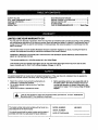
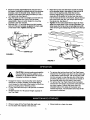
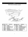
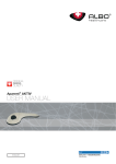
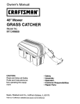
Owner's Manual
CRRFTSMnN
o
TRAC PACK
Model No. 486.24635
CAUTION:
Before using this product,
read this manual and follow
all Safety Rules and
Operating Instructions.
PRINTED IN U.S.A.
•
•
•
•
•
Safety
Assembly
Operation
Maintenance
Parts
SAFETY RULES .......................................................
FULL SIZE HARDWARE CHART .......................... .!
CARTON CONTENTS ........................................ i,..3
ASSEMBLY ...... ;..._..:............. ;., ............. :.......... ........
OPERATION ......................................................... ....
2
3
4
5
MAINTENANCE/STORAGE ..................................... 5
REPAIR PARTS ILLUSTRATION ........................... 6
REPAIR PARTS LIST ............................................... 6
SLOPE GUIDE .......................................................... 7
PARTS ORDERING/SERVICE ................. Back Page
LIMITED ONE YEAR WARRANTY ON
For one year from the date of purchase, when this Trac Pack is maintained and lubricatedaccording to the operating
and maintenance instructionsin the owner's manual, Sears will repair any defect in material or workmanshipfree of
charge. If this Trac Pack is used for commercial or rental purposes, this warranty applies for only 90 days from the
date of purchase.
This warranty does not cover repairs r_cessary because of operator negligence or abuse, includingthe failure to
m;dntainthe equipment accordingto instructionscontained in the owner's manual.
WARRANTY SERVICE IS AVAILABLE BY CONTACTING THE NEAREST SEARS SERVICE CENTER/DEPARTMENT IN THE UNITED STATES.
This warranty applies only while this product is in the United States.
This warranty gives you specificlegal rights,and you may also have other dghtswhich vary from state to state.
Seam, Roebuck and Co. D/817 WA. Hoffman Estates, Chicago, IL 60179
Any power equipment can cause injuryif operated improperlyor if the user does not understand how to operate the
equipment. Exercise caution at all times, when using power equipment.
•
•
•
Read this owners manual before attempting to
assemble or operate the spreader.
Do not allow anyone to ride on or sit on Trac Pack
attachment.
Never allow childrento operate the tractor.
,_
Before operating vehicle on any grade (hill) refer to
the safety rules in the vehicle owner'smanual conceming safe operationon slopes. Refer also to the
slope guide on page 7 of this manual. Stay off steep
slopes!
Look for this symbol to point out important safety precautions. It mean--Attantlonll
Become alertf! Your safety Is Involved.
The model number and serial numbers will be found on a
decal attached to the hitchbracket.
You should record beth the serial number and the date of
purchase and keep in a safe place for future reference.
MODEL NUMBER:
SERIAL NUMBER:
DATE OF PURCHASE:
486.24635
HARDWARE
SHOWN FULL SIZE
)
L
J
G
H
©
D
J
E
J
Ref. Qty.
No.
A
B
C
D
2
2
6
6
Description
Ref, Qty.
No.
Shoulder Bolt
3/8" x 1" Hex Bolt
5/16" x 3/4' Hex Bolt
5/16" Hex Lock Nut
E
F
G
H
/
CARTON CONTENTS
1.
2.
3.
4.
5.
Tool Box
Mounting Bracket, Left Hand
Mounting Bracket, Right Hand
Brace Strap
Hitch Bracket
F
1
4
2
1
3
Description
3/8" Flanged Lock Nut
Bushing
Clevis Pin
1/8" Hairpin Clip
2
3
FOR TRACTORS RESEMBLING FIGURE 2:
• Remove the bolt and nut from the hole on each side
of the tractorframe as shown in figure 3,
• Assemble two shoulder boltsand 3/8" flanged lock
nuts to the now empty holes. Tighten. See figure 3.
TOOLS REQUIRED FOR ASSEMBLY
(1)
(1)
(1)
(2)
(2)
3/4" Wrench or Adiustable Wrench
11/16' Wrench or Adjustable Wrench
5/8" Wrench or Adjustable Wrench
9/16" Wrenches or Adjustable Wrenches
1/2" Wrenches or Adjustable Wrenches
•
Remove the hardware pack and all parts from the
carton. Be sure the carton is empty before discarding,
Lay out ell parts and hardware as shown on page 3.
•
SHOULDERBOLT
FOR TRACTORS RESEMBUNG FIGURE 1:
• Remove the boltfrom the hole on each side of the
tractorframe as shown in figure 1.
• Assemble the two shoulder boltsto the now empty
holes. Tighten. See figure 1,
,3/6.FLANGED
_LOCKNUT
FIGURE 3
•
Assemble the right and left mounting brackets to the
hitchbracket using four 5/18' x 3/4" hex bolts and
5/16" hex lock nuts, Do not tighten yet. See figure 4,
LEFT HAND
MOUNTINGBRACKET_J
_14a.Mm,,
SHOULDER BOLT
RIGHT HAND
_
MOUNTINGBRACKET _
FIGURE 4
FIGURE 1
_
HITCH BRACKET
7
RIGHTHAND
MOUNTING
BRACKET
FIGURE
5/16. HE)(
dl . /
L/
5/16"x 3/4"
HE)( BOLT
FOR BOTH TYPES OF TRACTORS
• Assemblethe brace strap to the mounting brackets
usingtwo 5/16' x 3/4" he:<bolts and 5/16" hex lock
nuts. Do not tighten yet. See figure 5.
• Assemble two 3/8" x 1• hax bolts, bushingsand 3/8"
flanged lock nuts to the slots in the hitch bracket. Do
not tighten yet. See figure 5.
Assemble the right hand and left hand mounting
brackets to the hitch bracket usingfour 5/16" x 3/4"
hex bolts and 5/16" hex lock nuts. Do not tighten
yet. See figure 2.
LEFT HAND
MOUNTING
J
1.7
5/6. x 1"
HE)( BOLT_,_tl
5/16" x3/4"
HEXBOLT
5/16. x 3/4"
HEX BOLT
BRACESTRAP
2
FIGURE
4
5
_ _*
•
•
•
Place the loosely assembled frame onto the rear of
the b'actor,hooking the notched ends of the mounting
brackets under the shoulder bolts, Attach the hitch
bracket to the tractor hitchusing the clevis pin and a
1/8" hairpin clip. See figure 6.
Align the frame so that it is straight and level with the
tractor. Tighten the four 5/16" x 3/4" hex bolts
(assembled in figure 4) which fasten the mounting
brackets to the hitch bracket.
Slide the 3/8" x 1" hex boltsalong the hitch bracket
slots untilthey are bumped up against the back edge
of the tractor hitch.Tighten. See figure 6.
3/8" x 1"
HEXBOLT'-----.
I
I
I
I
t
•
•
Place the tool box onto the frame so that the heads
of the shoulder boltsin the bottom of the tool box fit
down intothe keyhole slots. Slide the tool box
forward, slightlytilting up the back end, untilthe
clevis pins in the bottomof the tool box drop down
into the holes at the rear of the frame. Secure the tool
box to the frame with two 1/8" hairpin clips through
the clevis pins. See figure 7.
Tighten the two bolts (assembled in figure 5) which
fasten the brace strap to the mountingbrackets. The
strap keeps the frame at the correct alignmentwidth
when removingand reattachingthe frame and the tool
box.
SHOULDER
BOLT
F
6
[o]"J=1: ,JIII
&
•
•
CAUTION: Vehicle braking and stability
may be affected with the addition of an
accessory or en attachment. Be aware of
changing conditions on slopes.
Engage the tractor clutch smoothly whert starting
the tractor in motion. Sudden, full throttle starts
could cause the front end of the tractor to lift off the
ground, causing loss of steering control.
Fill the Trac Pack with up to 100 pounds of material
or tools.
•
Do Not exceed the 100 pound weight capacity of
the Trec Pack.
•
•
Rinse or wipe off the Trac Pack after each use.
Do not store with material in the tool box.
•
To remove the tool box from the Trac Pack frame,
'remove the 1/8" hairpin clips from the two clevis pin
in the bottom of the tool box. Lift up the rear of the
tool box enough to raise the pins o,t of the frame
end then pull back and up tO remove the heads of
the shoulder bolts from the slots in the frame.
• To remove the Trac Pack frame from the tractor,
remove the 1/8" hairpin clip end the clevis pin from
the hitch bracket. Unhook the frame from the
shoulder bolts on the sides of the tractor and
remove the frame. The shoulder bolts may be left
permanently attached.
•
Store inside in a clean, dry area.
REPAIR
PARTS
FOR MODEL
486.24635
9
15
/
19
/
14
16
\
16
REF.
NO.
PART
NO.
QTY,
DESCRIPTION
REF.
NO.
PART
NO.
QTY.
1
2
3
4
5
6
7
8
9
10
11
47492
47493
47525
44044
43013
43088
43070
738-0255
46556
24560
24559
1
1
2
2
4
4
2
2
2
1
1
Tool BOX
Tool Box Lid
Hex Bolt, 1/4-20 x 4-1/2" Lg.
Clevis Pin, 3/8" x 3/4" Lg.
Hex Lock Nut, 1/4-20 Thd.
Washer, 1/4=
Washer, 3/8"
Shoulder Bolt, 1/4-20 x .36" Lg.
I Push Nut, 3/8"
Mounting Bracket, Right Hand
i Mounting Bracket, Left Hand
12
13
14
15
16
17
18
19
20
21
24567
24561
738-0234
47572
43182
43064
43343
711-0309
43001
23625
47494
1
1
2
4
6
6
3
1
2
2
1
DESCRIPTION
Brace Strap
Hitch Bracket
Shoulder Bolt, 3/8-16 x 5/8" Lg.
Hex Lock Nut, Flanged 3/8-16 Thd.
Hex Bolt, 5/16-18 x 3/4" Lg.
Hex Lock Nut, 5/16-18 Thd.
Hairpin Clip, 1/8" (#4)
Clevis Pin, 5/8" x 1.2' Lg.
Hex Bolt, 3/8-16 x 1" Lg.
Bushing, Pivot
Owners Manual
9rmc
• G$
"M
I
10•
j CAOT,ON:
O°n o 1tey°u
1
excess of 10 degrees. Operate up and down slopes, never acmes the
face of slopes. Avoid sudden turns or maneuvers.
For in-home major brand repair service:
Call 24 hours a day, 7 days a week
1-800-4-MY-HOME (1-800-469-4663)
Para pedir servicio de reparaci6n a domicilio-
1-800-676-5811
In Canada for all your service and parts needs call - 1-600-665-4455
Au Canada pour tout le service ou les pibces
For the repair or replacement parts you need:
Call 7 am - 7 pm, 7 days a weel_
1-800-366-PART
(1-800-366-7278)
Para ordenar piezas con entrega a domicilio - 1-800-659-7084
For the location of a Sears Parts and Repair Center in your area:
Call 24 hours a day, 7 days a week
1-800-488-1222
For information on purchasing a Sears Maintenance Agreement
or to inquire about an existing Agreement:
Call 9 am - 5 pm, Monday - Saturday
1-800-827-6655
TheService
SideofSears"
PRINTED IN US.A,
FORM
NO. 47494