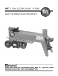
1
DR® LEAF & LAWN VACUUM
OPTIONAL ACCESSORIES
SAFETY & OPERATING INSTRUCTIONS
READ AND UNDERSTAND THIS MANUAL AND ALL INSTRUCTIONS
BEFORE USING YOUR NEW ACCESSORY
And congratulations on your purchase of a new DR LEAF and LAWN VACUUM Optional Accessory!
We have done our utmost to ensure that your DR LEAF and LAWN VACUUM Optional Accessory will be one
of the most trouble-free and satisfying pieces of equipment you have ever owned. Please let us know of any
questions or problems you may have. We want to answer or correct them as quickly as possible. When you
do call, please have your order number handy. For technical assistance, please call Toll-Free 1-800-DROWNER (376-9637) and one of our Technical Support Representatives will be happy to help you. We also
hope to hear from you on how much you like your new helper.
In addition, please tell your friends about your new DR LEAF and LAWN VACUUM Optional Accessory!
Having DR Owners spread the word about our products and our way of doing business is the best advertising
we can have, and the best way to help us provide even better service in the years to come.
Thanks once again!
for all of us at
Country Home Products, Inc.
SALES MANAGER
COPYRIGHT
©2006 Country Home Products, Inc. All rights reserved.
DR® Power Equipment
A division of Country Home Products®
127 Meigs Road
Vergennes, VT 05491
Toll-free phone: 1-800-DR-OWNER (376-9637)
Fax: 1-802-877-1213
Web site: www.dr-owner.com
ii
DR® LEAF and LAWN VACUUM Optional Accessories
Table of Contents
CHAPTER 1............................................................................................................................. 1
INTRODUCING THE DR OPTIONAL ACCESSORIES ................................................... 1
Conventions used in this manual ................................................................................... 1
CHAPTER 2............................................................................................................................. 2
GENERAL SAFETY RULES............................................................................................... 2
CHAPTER 3............................................................................................................................. 3
DR LEAF AND LAWN VACUUM OPTIONAL ACCESSORIES ....................................... 3
Connecting and Using the Optional Hand Vacuum Attachment (Kit No. 18789) ...... 3
Installing and Using the Optional Bagging Accessory................................................... 6
Installing and Using the Optional Mulch-Discharge Attachment (Kit No. 18791)...... 8
Installing the Optional Universal Lawn Deck Adapter ................................................. 10
CHAPTER 4........................................................................................................................... 19
PARTS LISTS AND SCHEMATIC DIAGRAMS.............................................................. 19
Parts List - Hand Vacuum Hose Assembly (Kit No. 18789) ........................................ 19
Schematic Diagram - Hand Vacuum Hose Assembly.................................................. 20
Parts List - Bagging Accessory (Kit # 18796 Commercial, # 18795 Premier Model) . 21
Schematic Diagram - Bagging Accessory ..................................................................... 21
Parts List - Mulch-Discharge Hose (Kit No. 18791).................................................... 22
Schematic Diagram - Mulch-Discharge Hose .............................................................. 22
Parts List - Universal Lawn Deck Adapter (Kit No. 18794) .......................................... 23
Schematic Diagram - Universal Lawn Deck Adapter.................................................... 24
CALL TOLL FREE 1-800-DR-OWNER
iii
CHAPTER 1
INTRODUCING THE DR OPTIONAL ACCESSORIES
This manual will help you set up and safely operate your new DR LEAF and LAWN VACUUM Optional
Accessory. Careful adherence to the safety and operating instructions in this manual will ensure many years
of productive use.
Please let us know of any questions you may have. We want to answer them as quickly as possible. When
you do call, please have your order number handy. For technical assistance, please call Toll-Free 1-800-DROWNER (376-9637) and one of our Technical Support Representatives will be happy to help you.
Conventions used in this manual
THIS INDICATES A HAZARDOUS SITUATION, WHICH, IF NOT AVOIDED, COULD RESULT IN DEATH OR
SERIOUS INJURY.
THIS INDICATES A HAZARDOUS SITUATION, WHICH, IF NOT AVOIDED, COULD RESULT IN MINOR OR
MODERATE INJURY.
THIS INFORMATION IS IMPORTANT IN THE PROPER USE OF YOUR MACHINE. FAILURE TO FOLLOW
THIS INSTRUCTION COULD RESULT IN DAMAGE TO YOUR MACHINE OR PROPERTY.
Tip: This is a helpful hint to guide you in getting the most out of your DR LEAF and LAWN VACUUM
Optional Accessory.
Tools Needed: This indicates you will need a special tool to perform a maintenance function on your
Optional Accessory.
NOTE: This information may be helpful to you.
If you are ever unsure about an action you are about to take, don’t do it, contact Country Home Products’
toll-free support at 1-800-DR-OWNER (376-9637) for help or information.
1
DR® LEAF and LAWN VACUUM Optional Accessories
CHAPTER 2
GENERAL SAFETY RULES
•
•
•
•
READ THIS SAFETY AND OPERATING MANUAL BEFORE YOU USE THE DR LEAF AND LAWN VACUUM
OPTIONAL ACCESSORY. ALSO, REVIEW THE SAFETY AND OPERATING MANUAL FOR YOUR SYSTEM.
INSPECT THE AREA WHERE YOU WILL BE WORKING. THE SITE MUST BE FREE OF POTENTIALLY
HAZARDOUS OBSTACLES (E.G., STONES, GLASS AND METAL OBJECTS SUCH AS CANS).
TURN OFF YOUR LAWN TRACTOR AND DR LEAF AND LAWN VACUUM ENGINES BEFORE
DISCONNECTING ANY HOSES TO INSTALL OR REMOVE YOUR ACCESSORY.
WEAR EYE PROTECTION WHENEVER THE BLOWER IS RUNNING.
CALL TOLL FREE 1-800-DR-OWNER
2
CHAPTER 3
DR LEAF AND LAWN VACUUM OPTIONAL ACCESSORIES
This chapter outlines a few simple steps you will need to follow to set up and use your new Optional
Accessories that are available for your DR LEAF and LAWN VACUUM. If you have any questions at all,
please feel free to contact our Customer Service Representatives at our toll free number:
1-800-DR-OWNER (376-9637).
Connecting and Using the Optional Hand Vacuum Attachment (Kit No. 18789)
In addition to towing the DR LEAF and LAWN VACUUM with your lawn tractor, the system also allows you
to vacuum flower beds, around trees and other places that you cannot mow with your lawn tractor.
•
•
•
BEFORE PERFORMING THIS PROCEDURE, STOP THE BLOWER ENGINE AND DISCONNECT THE SPARK
PLUG WIRE.
IF THE VACUUM HOSE BECOMES CLOGGED WITH DEBRIS, STOP THE ENGINE AND DISCONNECT
THE SPARK PLUG WIRE BEFORE ATTEMPTING TO CLEAR THE BLOCKAGE.
WEAR EYE PROTECTION WHENEVER THE BLOWER IS RUNNING.
USE CARE NOT TO ALLOW THE NOZZLE OPENING TO COME IN FULL CONTACT WITH THE GROUND
WHILE VACUUMING. DIRT, STONES AND OTHER SOLID OBJECTS MAY BE PICKED UP AND INGESTED
INTO THE BLOWER ASSEMBLY.
NOTE: The Hand Vacuum Hose shipped partially assembled. The following instructions detail the steps required
to assemble the Handle Bar to the Nozzle and the Support Tie for the Hose (Figure 1).
Handle Ring
Parts Supplied:
(2) 5/16" Lock Nut
(1) Support Tie
(1) Handle Bar Assembly
(1) Hose with Nozzle
Nozzle Bolts and
Lock Nuts (2 places)
Tools Needed:
• Scissors or Diagonal Cutter
• 1/2" Wrench or Socket
Eyebolt
Handle Bar
Nozzle
Support Tie
Figure 1
3
®
DR LEAF and LAWN VACUUM Optional Accessories
Ratchet Block
1. The Handle Ring is shipped in a position suitable for packaging with the Ring Clamp Bolt only partially
tightened. Rotate the Handle Ring upward but do not tighten at this time (Figure 1).
2. Locate the two (2) Bolts protruding from the Nozzle and align the two (2) holes at the end of the
Handle Bar and add a Lock Nut on each Bolt (Figure 1). Tighten the Lock Nuts using the 1/2" wrench.
3. Thread the Support Tie through the Eyebolt and wrap it around the Hose. Pass the end through the
Ratchet Block on the end of the Support Tie (Figure 1).
4. Pull the excess Support Tie through the Ratchet Block. Leave the Tie loop slightly larger than the
diameter of the Hose. Do not over-tighten (Figure 1).
5. Cut off excess Support Tie length.
6. Standing in a normal operating position (Figure 4), adjust the Handle Ring to a comfortable location
and tighten the Handle Ring Clamp Bolt securely using the 1/2" wrench.
The Vacuum Attachment can be attached to your Leaf and Lawn Vacuum using the following steps:
1. Disconnect the Blower Inlet Hose from your lawn deck
Hose Adapter by unhooking the two (2) Flexible Latches
(Figure 2).
2. Connect the Vacuum Attachment with attached nozzle by
aligning the Latches (Figure 3) and slipping the Vacuum
Attachment Hose into the Inlet Hose. Pull the Flexible
Latches into place (Figure 3) to secure the hoses.
Inlet Hose
3. Start the engine and adjust the throttle to fast (Rabbit).
4. While holding the Hand Vacuum Nozzle just above the
ground at an angle, sweep the area side to side that you
wish to vacuum (Figure 4).
Pull and
Unhook Latches
Tip: Hold the vacuum nozzle at a slight angle to the ground
so that it doesn’t suck right down on the ground. This
allows air to continue to flow into the nozzle while you
are vacuuming.
Figure 2
Hose Adapter
Sweep nozzle side to side
Blower Inlet Hose
Hand Vacuum Hose
Latches
Vacuum with nozzle at an angle
Figure 4
Figure 3
CALL TOLL FREE 1-800-DR-OWNER
4
Tip: When vacuuming leaves off mulched areas, hold the nozzle just above the leaves and lower it slowly to
determine the height that will pickup the leaves and not the mulch.
Tip: When vacuuming leaves in an area with loose brush, twigs and branches; step on them to hold them
down so as not to ingest them into the vacuum nozzle (Figure 5). They may clog or puncture a hole in
the vacuum hose. Once you have cleared the area of leaves, pick up, and chip the twigs and sticks that
you uncovered during vacuuming.
Tip: Avoid dragging the Vacuum Hose over curbs, stonewalls, or piles of cut branches. The hose is tough,
but can puncture on sharp objects.
DO NOT VACUUM IN SANDY AREAS WHERE LARGE QUANTITIES OF SAND WILL BE VACUUMED
WHILE MOWING OR VACUUMING. SAND WILL ERODE THE VACUUM HOUSING. CHECK FOR PIN
HOLES AFTER EACH USE AND REPLACE THE HOUSING WHEN PIN HOLES DEVELOP.
Hold Down Twig with Boot
Small Branch
Uncovered
Vacuum Nozzle
Figure 5
5
DR® LEAF and LAWN VACUUM Optional Accessories
Installing and Using the Optional Bagging Accessory
The DR LEAF and LAWN VACUUM can utilize nine (9) Bagger Box Inserts in the Commercial model (6 for
the Premier) that fit into the Collector Box for ease of bagging leaves and grass (Figure 6). For proper
bagging operation, you MUST install all boxes in the Collector Box.
BEFORE PERFORMING THIS PROCEDURE, STOP THE BLOWER ENGINE AND DISCONNECT THE SPARK
PLUG WIRE.
Commercial model: (Kit No. 18796)
1. Remove the Rear Panel of the Collector Box by
releasing the six (6) Flexible Latches and lift it off the
pins protruding on the top corners.
2. Form the nine (9) individual cardboard leaf bag
holders into boxes and insert a biodegradable leaf bag
or 30 gal. Heavy-Duty trash bag (supplied by the user)
into each box, folding the top of the bag over the top
edge of the box (Figure 6).
Insert Center Box Last
Fold Bag Over
Edge of Box
9-Individual
Bagger Boxes*
NOTE: Fold down the corners of the Bag Holder to stiffen
the assembly (Figure 7).
3. Place the nine (9) boxes into the Collector Box starting
at the front and working toward the rear.
Tip: Installation is easier if the outside boxes are placed
first in each row, followed by inserting the center box
between them (Figure 6).
4. Replace the Rear Panel by re-hanging it on the pins
protruding on the top corners and re-hook the six (6)
Flexible Latches.
*6 for the Premier model
Figure 6
Corner Folded Down
Inside Bagger Box
Figure 7
CALL TOLL FREE 1-800-DR-OWNER
6
Premier model: (Kit No. 18795)
Outer Panel
Pre-formed Edge
Inner Panel
Slide
Side Spacer
Figure 8
Pre-formed Notch
Shown with Top removed
Spacer Tube
Side Spacer
Front
Perpendicular surface
facing out
Rear
Figure 9
7
DR® LEAF and LAWN VACUUM Optional Accessories
1. Remove the Rear Panel of the Collector Box by
releasing the six (6) Flexible Latches and lift it off the
pins protruding on the top corners.
2. Install the supplied Bagger Spacers inside the
Collector Box by first releasing the Flexible Latches
holding down the Centrifugal Separator (top).
3. Install a side Bagger Spacer on the left Side Panel of
the Collector Box by inserting the formed edge of the
Spacer in between the inner and outer wall of the left
Side Panel of the Collector Box (Figure 8).
Tip: Raise the Centrifugal Separator (top) just enough
and start at the back of the Collector Box left Side
Panel, hooking the formed edge of the Bagger Spacer
over the inner panel and in between the Outer Panel
and Inner Panel, and sliding the Spacer along toward
the front until the support is completely inside the
Collector Box (Figure 8).
4. Repeat this procedure for installing a side Bagger Spacer
on the right Side Panel.
5. Install a Bagger Spacer Tube in the front of the
Collector Box by raising the Centrifugal Separator
(top) just enough to insert it into the Pre-Formed
Notches in the left and right Bagger Spacers. Note
the shape of the Spacer Tube; it will only go in one
way. The outside surface of the Spacer Tube must be
perpendicular to the Top (Figure 9).
6. Form the individual Leaf Bag Holders into boxes and
insert a biodegradable leaf bag or 30 gal. Heavy-Duty
trash bag (supplied by the user) into each box, folding
the top of the bag (Figure 6) over the top edge of the
box.
NOTE: Fold down the corners of the Bag Holder to stiffen
the assembly (Figure 7).
7. Place the six (6) boxes into the Collector Box starting
at the front and working toward the rear.
Tip: Installation is easier if the outside boxes are placed
first in each row, followed by inserting the center box
between them (Figure 6).
8. Install a Bagger Spacer Tube at the rear of the
Collector Box by raising the Centrifugal Separator
(top) just enough to insert it into the Pre-Formed
Notches in the left and right Bagger Spacers. Again,
note the shape of the Spacer Tube; it will only go in
one way. The outside surface of the Spacer Tube
must be perpendicular to the Top (Figure 8).
9. Re-hook the Centrifugal Separator (top) Latches and
replace the Rear Panel by re-hanging it on the pins
protruding on the top corners, and then re-hook the
six (6) Flexible Latches.
Installing and Using the Optional Mulch-Discharge Attachment (Kit No. 18791)
In addition to vacuuming and chipping with the DR LEAF and LAWN VACUUM, the system also allows you
to discharge material for mulch in a specific area. This attachment is used in conjunction with the hand
vacuum attachment. The vacuum attachment hose is used to vacuum the material out of the Collector Box.
BEFORE PERFORMING THIS PROCEDURE, STOP THE BLOWER ENGINE AND DISCONNECT THE SPARK
PLUG WIRE.
1. Disconnect the Collector Box Inlet Hose from the
Blower Exit Elbow Assembly by releasing the two
(2) Flexible Latches (Figure 10).
Pull and Unhook
Flexible Latches
Collector Box Hose
2. Push the Collector Box Inlet Hose behind the
Blower Exit Elbow (Figure 11), connect the Mulch
– Discharge Hose to the Blower Exit Elbow, and
secure in place with the two (2) Flexible Latches
(Figure 11).
Blower Exit Elbow
3. Disconnect the Blower Inlet Hose from your lawn
tractor Hose Adapter (Figure 2 on page 4) and
connect the Hand Vacuum Hose to the Blower
Inlet Hose (Figure 3 on page 4).
4. Remove the Rear Panel of the Collector Box.
5. Direct the Mulch-Discharge hose in the selected
area to receive the material (Figure 12), start the
engine and adjust the Throttle to Fast (Rabbit).
Figure 10
Tip: Avoid dragging the Mulch-Discharge and
Vacuum Hoses over curbs, stonewalls, or piles
of cut branches. The hoses are tough, but can
puncture on sharp objects.
Collector Box Hose
Tip: You may want to place stones beside the end of
the hose to position and direct the discharge.
6. Vacuum out the Collector Box using the Hand
Vacuum Attachment (Figure 12).
Mulch-Discharge Hose
Flexible Latch
Blower Exit Elbow
Figure 11
CALL TOLL FREE 1-800-DR-OWNER
8
DO NOT STAND OR ALLOW PEOPLE OR PETS NEAR THE DISCHARGE OPENING. MATERIAL IS EXITING
THE HOSE AT A HIGH RATE AND COULD CAUSE INJURY.
Discharge Hose
NO STANDING!!
Figure 12
9
DR® LEAF and LAWN VACUUM Optional Accessories
Installing the Optional Universal Lawn Deck Adapter (Kit No. 21168)
The design of the DR Universal Lawn Deck Adapter is adaptable to a variety of Mower Decks as found on the
various makes of tractors and mowing machines.
The intension of the information provided here is to show a typical method for obtaining measurements and
determining shapes and contours for proper fitting of the unit to your machine. Your particular machine may
require slightly different or additional operations to obtain the best fit.
•
•
•
TURN OFF THE IGNITION AND/OR REMOVE THE SPARK PLUG WIRE(S) ON YOUR MOWER BEFORE
STARTING THIS PROCEDURE.
BE SURE TO STABILIZE YOUR MACHINE ON FLAT TERRAIN AND APPLY THE PARKING BRAKE BEFORE
STARTING THIS PROCEDURE.
ALWAYS WEAR EYE PROTECTION WHEN CUTTING OR DRILLING WITH POWER TOOLS.
Kit Parts List:
•
•
•
•
Universal Deck Adapter
Template Wire
Hinge Hardware:
(2) Hinge Brackets
(1) Hinge Pin w/two (2) Push Nuts
(1) Bracket Plate
Mounting Bolts and Nuts
Instruction Sheet
Tools Needed:
•
•
•
•
•
•
•
•
•
•
•
•
Jig Saw
Pencil or Fine Tipped White Marker
1/2" Wrench
Electric Drill w/1/4" and 3/8" Drill Bits
Pliers
Scissors or Utility Knife
C-Clamps or Spring Clamps
Masking tape
Straight Edge
Tape Measure
Square, Adjustable
File, Sand Paper or De-Burring Tool
CALL TOLL FREE 1-800-DR-OWNER
10
1. Before proceeding with the installation, familiarize yourself with the Parts, and the illustrations of
the Universal Lawn Deck Adapter as shown in Figure 13.
2. Thoroughly clean the exposed area of your Mower Deck so that it may be easily marked.
3. Remove the Hinge Pin from your Mower Deck Mounting Bracket (Figure 14) and remove the Discharge
Chute, Springs, and related parts from your Mower Deck. Do not remove the Mounting Bracket. (See
Reference Line instruction below). Save these parts for future use should you decide to return your Lawn
Mower Deck to its original configuration.
NOTE: You may wish to remove the Mower Deck from your Mower and place it on a bench at a comfortable
work height for these procedures.
Top
Front
Discharge
SIDE
(Vertical)
Base Plate
Hinge Pins
Rear
UNIVERSAL DECK ADAPTER
DR Mounting Brackets
BOTTOM
(Horizontal)
Figure 13
Area Beneath Mower
Mounting Bracket
Hinge Pin
Typical Lawn Tractor with Mower Deck
Discharge Chute
Figure 14
11
DR® LEAF and LAWN VACUUM Optional Accessories
Mower Deck
Mounting Bracket
Installing Your Deck Adapter
Reference Line
The following outlines the typical steps necessary for
installing a Universal Lawn Deck Adapter to your Lawn
Tractor. The procedure requires patience, around two
(2) hours to complete, and skill working with a Jig Saw
to match contours.
1. Establish a Reference Line.
Straight Edge
Figure 15 shows the typical location of a Reference Line
on your Mower Deck. The location of this line is
determined by finding a position that allows the
Universal Lawn Deck Adapter to cover the entire
Figure 15
Mower Deck opening (Figure 15) and provides
clearances for the Hose and Hose Adapter when
operating. This will vary depending upon the make and
Mounting Bracket
model of your machine. Frequently it is located in line
with your Mower Deck Mounting Bracket.
Straight Edge
a) Place a Straight Edge against the front of the
Mounting Bracket and clamp it in place (Figure 16).
Lightly draw a Reference Line as shown in Figure 15.
b) Place a Square on the Straight Edge (Figure 17)
and determine if the side of the Universal Deck
Adapter would cover the Discharge Opening if it
were located there. If not, locate the proper point
and transfer that location to the top of your Mower
Deck. Re-locate the Mounting Bracket to that
position if necessary; keeping it parallel to the
Reference Line. This will become the Reference
Line for making the template.
Figure 16
c) Measure the Height (Figure 18) from the bottom to
the top of the Mower Deck at the Reference Line.
Make a note of it here as HEIGHT A ____________.
d) Then measure the Height from the bottom of the
Chute to the lowest point along the Reference Line
at the opposite side. Make a note of it here as
HEIGHT B ______________.
Figure 18
Figure 17
CALL TOLL FREE 1-800-DR-OWNER
12
2. Make the vertical (side) Template.
a) Place the Straight Edge against the edge of the Mounting Bracket and clamp it in place (Figure 16 on
page 12).
b) Draw a line across the top of your Mower Deck. Using the Square, extend the line down the sides at each
end (Figure 17 on page 12). Extending the Square from the Straight Edge to the contours can make
more Reference Line points.
NOTE: Before using the Template Wire, it is helpful to straighten it. Clamp one end of the Wire in a vise and,
using pliers, pull the Wire to remove irregularities.
c) Clamp one end of the Template Wire at the side of the Discharge Chute (Figure 19) where you marked
the vertical Reference Line.
d) Now press the Wire tightly down against the contours of your Mower Deck, following the Reference Line
points to the opposite side (Figure 19). It is best to tape the Wire in place at various points to maintain
position as you bend.
e) After you form the wire down to the Base Line, cut off the surplus wire.
f)
Cut the tape holding the Template Wire in place and carefully remove the Template Wire from the Chute.
You will use the formed Wire to transfer the contours of the Discharge Chute to the Template.
Template Wire
Use tape if clamp
will not reach.
Form and Tape here
Form and Tape here
Forming the Template Wire
Figure 19
g) Place the formed Template Wire loosely against the Mower Deck along the Reference Line and check to
be certain it follows the contours.
h) Cut two (2) Template Boards (Figure 20) from the Kit corrugated Shipping Carton. One should be large
enough to cover the entire side (vertical) of the Universal Deck Adapter and the other should cover the
bottom (horizontal) area that will be cut from the Universal Deck Adapter.
Side (Vertical) Template
Bottom (Horizontal) Template
13
DR® LEAF and LAWN VACUUM Optional Accessories
Figure 20
i)
Place the Universal Deck Adapter on its side
(Figure 21) on the Template Board. Trace the
outline and cut the board to the outline. Make
note of the Front and Bottom on the Template
Board.
j)
Draw a line 1/2” from the bottom edge of the
Template Board (Figure 22). This represents the
bottom of the Discharge Chute or Baseline.
Tracing the Contour
Figure 21
k) Using HEIGHT A. from Step c) on page 12, draw
a horizontal line across the Template at the A
Height above the baseline. Do the same for
HEIGHT B at the rear of the Template. These
lines will insure that your Wire Template in the
next step will be horizontally accurate.
l)
Center the formed Wire (right and left) on your
Template Board (Figure 23), and bring the
formed Wire to the horizontal HEIGHT A and
tape it to prevent movement. Repeat the process
for the B HEIGHT at the rear edge of the
Figure 22
Template Board and tape it in place.
1/2"
Baseline
Template Cut to Shape and Marked
m) Tape the front and rear ends of the Wire and
then trace the contour of the Wire on to the
Template Board (Figure 23).
n) Cut the contour out of the Template Board
(Figure 24).
NOTE: Before tracing the Template contour directly on
the Universal Deck Adapter, it is best to try fitting Figure 23
the cut Template to your Mower Deck to note any
problems. This will reveal minor fit problems,
particularly in the area near the bottom of the
Discharge Chute where flanges and other
transitions occur. Cut and tape to modify the
template as needed to accept these subtle contour
changes. Apply the adjusted template to the
Universal Deck Adapter (Figure 25) and trace the
final contour.
Tracing the Template Wire
Template Board
Figure 24
Universal Deck Adapter
Figure 25
CALL TOLL FREE 1-800-DR-OWNER
14
3. Make the horizontal (bottom) Template.
a) Using the vertical Reference Lines (Figure 17 on page 12),
place the Template Board beneath the Discharge Chute
with the leading edge aligned to the Reference Lines
(Figure 26) and centered right to left.
b) Clamp the Template Board in place and trace the outer
edge of the Discharge Chute on to the Template Board
(Figure 26).
Figure 26
c) Cut the outline from the Template Board. Center the
Template Board to match the Discharge Opening that
you traced on the side, tape it in place, and trace the
contour (Figure 27) on to the Universal Deck Adapter.
Your finished markings should look similar to those in
(Figure 28). Note how the two (2) patterns match at the
common edge.
Figure 27
Completed Template Contours on Deck Adapter
Figure 28
15
DR® LEAF and LAWN VACUUM Optional Accessories
4. Cut the Universal Deck Adapter.
a) Drill a Pilot Hole (Figure 29) near the Contour Line.
b) Insert the Blade of the Jig Saw and carefully cut
along the contours until the piece is free from the
Universal Deck Adapter (Figure 30). Clean the
burrs from the cut line.
c) The corners of the Universal Deck Adapter opening
where the side and bottom contours meet may
require minor adjustments for a final fit. Hold the
Universal Deck Adapter in place on your Mower
Deck and note any problem areas. Using the
marker, draw Reference Lines at the front and back
for revision. Remove the unwanted material using
the Saw or a File. It is best to cut in small amounts
and repeat to achieve the fit.
Hole for inserting
Saw Blade
Figure 29
Cut Shape removed from Adapter
Figure 30
5. Modify the Hinge Plate.
Because of the variations in Mower Decks designs, modifications may be required to the hinge installation to
achieve proper alignment between the Universal Deck Adapter hardware and your Mower Deck hardware.
Note the two (2) examples shown in (Figure 31).
Small Distance
Large Distance
Front
Figure 31
CALL TOLL FREE 1-800-DR-OWNER
16
Large Height Distance
1. Internal Mount
a) Slot the Universal Deck Adapter (Figure 32) to receive the Hinge Plate Arms. You can do this by
drilling 1/4” holes at the top and bottom of the slot locations and inserting the Saw Blade into the hole
to remove the remaining material or cutting directly from the edge of the contour.
b) Shims (Figure 32), made by tracing the outline and hole locations of the Bracket Plates or Mower Deck
Hardware onto a piece of material that was cut out of the Universal Deck Adapter, are then placed
beneath the hardware to bring it to level.
c) The Universal Deck Adapter Hinge with appropriate shimming, is inserted into the slots and then
bolted to the under side of the Universal Deck Adapter (Figure 32) with the Backing Plate mounted
externally.
Bracket Plate
Cut Slots
Deck Material for Shims
Shims
Figure 32
2. External Mount
You can also mount the Universal Deck Adapter Hinge Plate on top of the Universal Deck Adapter
(Figure 33).
Bracket Plate
Figure 33
Small Height Distance
We suggest shimming your Mower Deck Hardware as in the External Mounting above. Figure 34
shows sectional views of various hardware installations and typical shimming to achieve common
heights.
Mowing Deck
Mounting Bracket
Deck Adapter
Bracket
Bracket Plate
Shims
Shims
Bracket Plate
17
Figure 34
DR® LEAF and LAWN VACUUM Optional Accessories
6. Hinge Assembly
The Hinge hardware supplied with your Universal Deck Adapter accommodates a variety of hinge widths as
supplied by various manufacturers. Proper assembly is important. During use, the assembled hinge will look
as shown in (Figure 35). The force of the forward movement of the tractor holds the Mower Deck Mounting
Bracket toward the front of the assembly while in motion.
Push Nut
Push Nut
Mower Deck
Mounting Bracket
Front
Figure 35
7. Hose Attachment
Refer to your Leaf & Lawn Vacuum Safety & Operating Manual for details in connecting the Hose Adapter to
your Universal Lawn Deck Adapter.
CALL TOLL FREE 1-800-DR-OWNER
18
CHAPTER 4
PARTS LISTS AND SCHEMATIC DIAGRAMS
Parts List - Hand Vacuum Hose Assembly (Kit No. 18789)
NOTE: Part numbers listed are available through Country Home Products.
Ref# Part#
Description
01
02
03
04
05
06
07
08
09
10
11
12
13
14
15
16
Nozzle
Hose, Vacuum, 14 FT.
Clamp, Hose, 6"
Handle
Grip, 1"
Bolt, HCS, 5/16"-18 x 1"
Washer, Flat, 5/16" USS
Nut, Nylon Lock, 5/16"-18
Bolt, Eye, 5/16"-18 x 3"
Nut, 5/16"-18, ZP, GR2
Tie, Cable, 15"
Coupling
Keeper, Draw Latch, 4"
Rivet, Blind, Alum., 3/16" Dia. x .312"
Rivet, Blind, Alum., 3/16" Dia. x .1875"
Handle, Vacuum
19
188991
188741
186961
187421
150471
111581
112411
110761
109161
110691
127971
186761
189441
189291
164141
187001
DR® LEAF and LAWN VACUUM Optional Accessories
Schematic Diagram - Hand Vacuum Hose Assembly
CALL TOLL FREE 1-800-DR-OWNER
20
Parts List - Bagging Accessory (Kit # 18796 Commercial, # 18795 Premier Model)
NOTE: Part numbers listed are available through Country Home Products.
Ref# Part#
Description
01
02
03
Spacer, Bagger, Side, R/L
Spacer, Bagger, Tube, F/R
Holders, Leaf Bag
187851
187841
187661
Schematic Diagram - Bagging Accessory
21
DR® LEAF and LAWN VACUUM Optional Accessories
Parts List - Mulch-Discharge Hose (Kit No. 18791)
NOTE: Part numbers listed are available through Country Home Products.
Ref# Part#
Description
01
02
Hose, Discharge, 17 FT
Adapter, Male/Female, 6"
Coupling, Hose, Male, 6"
Latch, Draw
Clamp, Hose, 6"
Rivet, Blind, Alum., 3/16" Dia. x .312"
Rivet, Blind, Alum., 3/16" Dia. x .1875"
03
04
05
06
186741
186771
191951
186731
186961
189291
164141
Schematic Diagram - Mulch-Discharge Hose
CALL TOLL FREE 1-800-DR-OWNER
22
Parts List - Universal Lawn Deck Adapter (Kit No. 18794)
NOTE: Part numbers listed are available through Country Home Products.
Ref# Part#
Description
01
187271
Bracket, Mounting, Discharge
02
187301
Pin, Hinge, Mounting Bracket
03
187291
Base, Mounting Bracket
04
157321
Nut, 5/16", Push
05
192651
Adapter, Universal Deck
07
109131
Bolt, Carriage, 5/16"-18 x 1-1/2"
08
110761
Nut, Nylon Lock, 5/16"-18
09
186781
Adapter, Hose, 6-7", Male, R/C
10
189441
Keeper, Draw Latch, 4"
11
114781
Screw, Pan Head, 10-24 x 5/8"
12
118731
Nut, Nylon Lock, 10-24
16
111581
Bolt, 5/16"-18 x 1" HCS
17
112411
Washer, Flat, 5/16" USS
213531
Wire, Template Forming (not shown)
NOTE: An additional Mounting Discharge Bracket (187271), two (2) Bolts (109131), and two (2) Nylon
Lock Nuts (110761) have been included for your convenience in installing the Universal Deck
Adapter to your mower.
23
DR® LEAF and LAWN VACUUM Optional Accessories
Schematic Diagram - Universal Lawn Deck Adapter
CALL TOLL FREE 1-800-DR-OWNER
24
NOTES
25
DR® LEAF and LAWN VACUUM Optional Accessories
NOTES
CALL TOLL FREE 1-800-DR-OWNER
26
Daily Checklist for the DR LEAF and LAWN VACUUM
To help maintain your DR LEAF and LAWN VACUUM for optimum performance, we recommend you
follow this checklist each time you use your machine.
[ ] OIL: With the machine on a level surface, remove the oil fill cap and check the oil level.
Fill the reservoir according to the dipstick with SAE 30 HD motor oil. See page 25 of the Safety
& Operating Instructions for your DR Leaf and Lawn Vacuum.
[ ] GAS: Fill the gas tank with fresh, unleaded gasoline.
[ ] ENGINE: It is very important to keep the engine clean. Remove dirt and other debris from the
engine cooling fins and debris guard. A dirty engine retains heat and can cause damage
to internal engine components.
[ ] HARDWARE: Check all nuts and bolts to be sure that the components are secure.
[ ] FRAME: Check all welds to be sure that the frame is in tact and secure.
[ ] BLOWER HOSES: Inspect the blower hoses for holes, frayed, worn, kinked, or abraded areas.
Replace any damaged or worn hoses.
COUNTRY HOME PRODUCTS, Inc.
MEIGS ROAD, P.O. BOX 25, VERGENNES, VERMONT 05491
1-800-DR-OWNER (376-9637) • www.dr-owner.com
©2006 CHP, Inc. 189651A