1
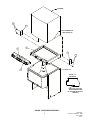
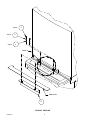
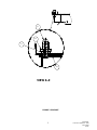
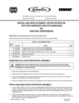
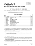
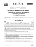
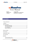
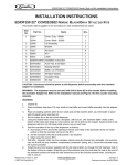
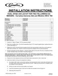
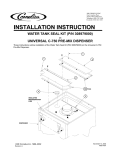
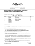
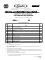
IMI CORNELIUS INC g One Cornelius Place g Anoka, MN 55303-6234
Telephone (800) 238-3600
Facsimile (612) 422-3246
ED150 “K” STYLE LID KITS,
P/N 629083204 AND 629083202
These “K”style kits apply to the following ice maker:
Ice Maker
Width
Manitowoc Q320/420
22I
Table 1. Loose-Shipped Parts
Item
No.
1
Part No.
Name
Qty.
52994
Cover, Gray (629083202)
1
52934
Cover, Black (629083204)
2
620027505
DF150 Ice Maker Lid Assembly
1
3
620027306
Bracket
2
4
70217
#8 Screw
6
5
50904
RTV
1
6
90221
Label
1
7
620909401
Installation Instruction
1
8
620701902
Acorn Nut, 8--32 Nylon
2
9
620701901
Sealing Washer
2
10
620037007
Baffle, Ice DF/ED150
1
11
621701903
#8 Nylon Washer
2
1. Unpack kit.
2. Insert a baffle assembly into the adapter lid.
3. Place (2) sealing washers (item 9) over studs and (2) flat washers (item11), then fasten in place with (2)
plastic acorn nuts (item 8).
4. Set ice maker lid on the top of the dispenser.
5. Using the slotted holes in the lid as a template, drill four (4) 9/64Idiameter holes at the bottom of the slots
(see detail A). Use extreme care not to drill into the hopper. Fasten the lid to the dispenser with four (4) #8
sheet metal screws, two on each side.
6. Seal the ice maker to the top of the dispenser as follows:
A.
Run beads of RTV around the opening in the lid and inside of the perimeter of the ice maker outline so
that the ice maker will set on the RTV.
1
620909401
Revised: September 8, 1998
March 1998
Rev B
B.
Set the ice maker onto the lid and position it as required.
C.
Wipe away the excess RTV.
7. Remove the two rear screws (only) installed in step 5. Use those screws to install the mounting brackets
(item3). Drill 9/64Idiameter holes into the ice maker cabinet using the bracket as a template. Use extreme
care not to drill into any ice maker components (condenser, tubing, etc.). Secure the brackets using the
screws provided
8. Follow the ice maker manufacturers instruction to complete the installation of the ice maker including the
bin thermostat if so equipped or required.
9. If the plastice acorn nuts interfere with the positioning of the plastic manual fill cover, it may be necessary
to make small notches in the back flange of the cover to clear the acorn nuts.
NOTE: Bin Thermostat must not interfere with the agitator rotation.
620909401
2
ICEMAKER
4
3
SEAL ICEMAKER TO
ITEM 2 WITH RTV
2
6
3
4
1
DETAIL ”A”
DETAIL ”A”
ENLARGED
DRILL 9/64” (.140” )DIA.
HOLES USING BOTTOM
OF SLOTTED HOLES AS A
TEMPLATE
FIGURE 1. DISPENSER ASSEMBLY
3
620909401
Revised: September 8, 1998
March 1998
Rev B
4 PLCS.
2 PLCS.
2 PLCS.
8
11
9
VIEW Z--Z
LINER OF LID
10
FIGURE 2. ED150 KIT
620909401
4
8
11
9
10
VIEW Z--Z
FIGURE 3. ED150 KIT
5
620909401
Revised: September 8, 1998
March 1998
Rev B