1
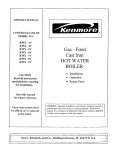
Service
and
Parts
Manual
BG
Engine
965-0251
11A75
Printed In U S A
Safety Precautions
*
DO NOTsmokeor use an openflame inthe vicinity of the
engine or fuel tank. Internalcombustionengine fuels are
highly flammable.
Fuel lines must be of steel piping, adequately secured,
and free from leaks. Piping at the engine should be approvedflexible line. Do not use copper piping for flexible
lines as copper will work harden and become brittle
enough to break.
Be sure all fuel supplies have a positiveshutoff valve.
It is recommended that you read your engine manual and become thoroughly acquainted with your equipment before you
start the engine.
1-1
This symbol is used throughout this
manual to warn of possible serious personal injury.
1-
This symbol refers to possible equipment damage.
Fuels, electricalequipment, batteries, exhaustgases and moving parts present potentialhazardsthat could result in serious,
personalinjury. Take careinfollowing these recommendedprocedures.
Safety Codes
0
0
All local,state andfederal codes shouldbeconsultedand
compliedwith.
This engine is not designedor intendedfor usein aircraft.
Any such use is at the owner’s sole risk.
General
Provideappropriate fire extinguishers and install them in
convenient locations. Use an extinguisher rated ABC by
NFPA.
Makesure that allfastenersonthe engineare secure and
accurately torqued. Keep guards in position over fans,
driving belts, etc.
If it is necessary to make adjustmentswhile the engine is
running, useextreme cautionwhen close to hot exhausts,
moving parts, etc.
Protect Against Moving Parts
0
0
Do not wear looseclothing in the vicinity of moving parts,
such as PTO shafts, flywheels, blowers, couplings, fans,
belts, etc.
Keep your hands away from moving parts.
Batteries
0
0
0
Before starting work on the engine, disconnect batteries
to prevent inadvertentstartingof the engine.
DO NOTSMOKEwhile servicing batteries. Leadacid batteries give off a highly explosive hydrogen gas which can
be ignitedby flame, electrical arcing or by smoking.
Verify battery polarity before connecting battery cables.
Connect negative cable last.
Fuel System
0
DO NOTfillfuel tanks while engine is running.
Exhaust System
Exhaustproducts of any internal combustionengine are
toxic and can cause injury, or death if inhaled. All engine
applications, especially those within a confined area,
should be equipped with an exhaustsystem to discharge
gases to the outside atmosphere.
0 DO NOT use exhaust gases to heat a compartment.
0
Makesure that your exhaust system is free of leaks. Ensure that exhaust manifolds are secure and are not
warped by bolts unevenlytorqued.
Exhaust Gas Is Deadly!
Exhaust gasescontaincarbon monoxide,a poisonousgasthat
mightcause unconsciousness and death. It is an odorless and
colorless gas formed during combustionof hydrocarbonfuels.
Symptoms of carbon monoxide poisoning are:
0 Dizziness
0 Vomiting
0 Headache
0 MuscularTwitching
Throbbing in Temples
0 Weakness and Sleepiness
If you experience any of these symptoms, get out intofresh air
immediately, shut downthe unitand do not useuntil it has been
inspected.
The best protection against carbon monoxide inhalation is
proper installationand regular, frequent inspectionsof the complete exhaust system. If you notice a change in the sound or appearance of exhaust system, shut the unit down immediately
and have it inspectedand repairedat once by a competent mechanic.
Cooling System
0 Coolants under pressure have a higher boilingpoint than
water. DO NOT open a radiator pressure cap when coolant temperatureis above212 degrees F (100 degrees C)
or while engine is running.
4
Keep The Unit And Surrounding Area Clean
0 Makesure that oily rags are not left on or nearthe engine.
0
Removeall unnecessary greaseand oilfromthe unit. Accumulated grease and oil can cause overheating and
subsequent engine damage and present a potential fire
hazard.
Redistribution or publication of this document,
by any means, is strictly prohibited.
c
TABLE.OF CONTENTS
.
.TITLE
PAGE
General Information .............................................
2
Specifications ...................................................
3
Dimensions and Clearances .......................................
4
Assembly Torques and Special Tools .............................
4
Engine Troubleshooting .........................................
5
Oil System ......................................................
6
Fuel System ......................................................
8
Ignition and Battery Charging ....................................
12
Starting System .................................................
17
Engine Disassembly .............................................
19
Engine Wiring Diagram ..........................................
31
t
Redistribution or publication of this document,
by any means, is strictly prohibited.
1
GENERAL INFORMATION
P
ENGINE MODEL REFERENCE
This manual contains proper information for the
servicing and overhaul of your Onan engine. Use the
PARTS CATALOG in the rear portion of this book to
help you with disassemblyand assembly procedures.
Identify your model by referring to the MODEL and
SPEC (specification) NO. as shown on the unit
nameplate. Always use this number and the engine
serial numberwhen making reference toyourengine.
Flywheel end of engine is considered the front. Left and right sides
are determined looking at front of engine.
How to interpret MODEL and SPEC NO.
If it is necessary to contact your dealer or the factory
about this engine, always supply the complete
MODEL and SPEC NUMBER as well as the SERIAL
NUMBER shown on the engine nameplate. The
engine nameplate is located on left side of blower
housing (end opposite oil filter).
Factory code for general identification purposes.
Specific Type:
S-MANUAL STARTING
MS-ELECTRIC STARTING
Factory code for optional equipment supplied.
Specification (Spec Letter) advances with factory
production modification.
Refer to the TROUBLESHOOT/NG GUIDE for
assistance in locating and correcting troubles which
may occur. If a major repair or overhaul becomes
necessary, the engine should be carefully checked
and necessary repairs made by a competent
mechanic. Maintain factory limits and clearances as
shown, replacing worn parts when necessary.
I WARNING I
TO AVOlD POSSIBLE PERSONAL INJURY OR
EQUIPMENT DAMAGE, AN AUTHORIZED SERVICE REPRESENTATIVE MUST PERFORM A l l
SER VICE,
Redistribution or publication of this document,
by any means, is strictly prohibited.
2
.
SP ECIFK A TIONS
This manual contains SI metric equivalents that follow immediately in parentheses
after the U.S. customary units of measure.
Engine Manufacturer .....................................................................
Onan
Engine Design.. ............................................ Four Cycle, Air-Cooled. Two Cylinder
i-lorsepower (3600 rpm) ......................................................................
78
Displacement (cubic inches) ................................................... 49.8 (816.22 crn )
Bore .......................................................................... 3-114 (82.55 mm]
Stroke ............................................................................ 3 (76.20 mm)
Compression Ratio ........................................................................ 7.0:l
Crankshaft ........................... .:. ................................ Horizontal. Ductile Iron
Valves ..................................................................... Mechanical. Poppet
Bearings (Main and Rod) ................................................................
Sleeve
Oil Capacity with Filter Change ..............................................
4 Pints (1.89 Iiti-es)
011Capacity Without Filter Change .......................................... 3.5 Pints (1.66 litresi
Battery Charging System .................................... 12 Volt. 15 Amp Flywheel Alternator
TUNE-UP SPECIFICATIONS
Tappets (Cold) Intake.. .........................................................
-008 (0-29rnm)
Exhaust.. ....................................................... -013 (0.33 mm)
Breaker Point Gap (Full Separation and Engine Cold) ........................ .021 inch (0.53 mm)
Spark Plug Gap ............................................................ .025inch (0.64 rnm)
Ignition Timing (Cold. Static Setting) ....................................................
21'BTC
3
Redistribution or publication of this document,
by any means, is strictly prohibited.
DIMENSIONS AND CLEARANCES
.
All dimensions and clearances given at room temperature at 7OoF
All values in inches unless otherwise specified
.
I
Minimum
Maximu rn
0.0025
0.006
0.0015
0.0038
0.01 2
0.0030
CAMSHAFT AND CRANKSHAFT
Crankshaft Main Bearing Journal to Bearing Clearance .........................
*Crankshaft End Play ..........................................................
Camshaft Bearing to Camshaft ................................................
Camshaft End Play ...........................................................
'Crankshaft Rod Journal to Rod Bearing .......................................
Connecting Rod End Play .....................................................
Timing Gear Backlash ........................................................
01;Pump Gear Backlash ......................................................
PISTON AND CYLINDER
Piston Pin in Piston ...........................................................
Piston Pin in Rod .............................................................
'Piston Ring Gap in Cylinder ...................................................
Piston Clearance in Cylinder-Measured . 10 Below Oil
Control' Ring. 90" from Pin ....................................................
Cylinder Bore-Standard Size .................................................
Crankshaft Main Bearing Journal-Standard Size ...............................
Crankshaft Rod Bearing Journal-Standard Size ...............................
b
0.003
0.0020
0.002
0.002
0.002
0.0033
0.01 6
0.003
0.005
0.0002
0.0002
0.010
0.0004
0.0007
0.020
004
3.249
1.9992
1.6252
.006
3.250
2.0000
1.6260
1/32
44"
45"
0.0010
0.0035
0.0015
44"
45"
0.0025
0.0040
0.0030
0.007
0.012
0.009
0.014
TAPPETS AND VALVES
"Valve Seat Width .............................................................
....................................
'Valve Face Angle ........................
'Valve Seat Angle .............................................................
Valve Stem to Guide-Intake ..................................................
Valve Stem to Guide-Exhaust ................................................
Tappet to Cylinder Block Clearance ...........................................
Tappet Adjustment (Cold)
'Intake ......................................................................
'Exhaust ....................................................................
*
1/8
.Frequently used overhaul values .
ASSEMBLY TORQUES AND SPECIALTOOLS
BOLT TORQUE
Gearcase Cover ..........................
Cylinder Head Bolts (Cold) ...............
Rear Bearing Plate Screws ................
Starter Mounting Bolts ....................
Connecting Rod Bolt .....................
Flywheel Cap Screw ......................
Other 5/16" Cylinder Block
Stud and Nuts ..........................
Oil Base .................................
Manifold Mounting Screws ................
Oil Pump .................................
FT.-LB.
8 .10
The following special tools are available from Onan .
For further information see TOOL CATALOG 90000 19.
14 .16
25 .27
18 .20
14 .16
35 .40
P
Valve Seat Driver
Valve Guide Driver
Oil Guide and Driver
Combination Bearing Remover (Main and Cam)
Combination Bearing Driver (Main and Cam)
Flywheel Puller
8 .10
18 .23
6 .10
7 .9
4
Redistribution or publication of this document,
by any means, is strictly prohibited.
ENGINE TROUBLESHOOTING
I
5
Redistribution or publication of this document,
by any means, is strictly prohibited.
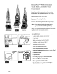
OIL SYSTEM
Do not overfill crankcase. Do not use service
CRANKCASE OIL
I
DS oil. Do not mix brands norgradesof motor
Change crankcase O i l every 50 operating hours and
only when engine is warm. (Exception: Drain initial oil
fill at 25 operating hours.)
oil. Engine damage could result from mixing non-compatible oils.
To drain, remove the 1/2-inch pipe plug on the rear
corner of the oil base. After oil drains, replace the pipe
plug and refill crankcase with 3-1/2 pints (4 pints if
changing filter) of a good quality detergent oil. Oil
must meet or exceed the API (American Petroleum
Institute) designation SEorSEKC. SeeFigures 1and
2. For temperatures above 30°F, use SAE 30 oil; for
temperatures below 3OoF, use 5W30 or 1OW.
In extremely dusty conditions or in very cold weather,
change oil at least every 25 hours of operation.
LWAYS REPLACE
IGHTLY O R OIL
LEAKAGE MAY OCCUR
FIGURE 2 OIL DRAlN LOCATION
WARY:NG: 23 Edc'!'
REMD'IE O ! L CAP
WH ENGIW iwr+
NING. O!L WILL
@LOWOUT CAUSING
OIL FILTER
Change the crankcase oil filter every ?OO hours;
change more frequently in extremely dusty cond i t i o n s . Remove t h e f i l t e r b y t u r n i n g
counterclockwise with a filter wrench. Before installinganewfitter,coatthegasketon thefilterbasewith a
light film of new oil. Install.byturning clockwise until a
light friction is noted, then turn an additional 1/2 turn.
POSS BLE INJURY.
*
CAUTION- DO NOT OVERFILL
Crankcase Breather
A D D ONE PINT
This engine uses a crankcase breather valve for
maintaining crankcase vacuum. if the crankcase
becomes pressurized as evidenced by oil leaks at the
seals, clean baffle pack and valvein asuitablesolvent.
See Figure 3.
FIGURE 1. CRANKCASE OIL FILL
6
Redistribution or publication of this document,
by any means, is strictly prohibited.
.. .
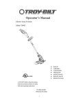
OIL PUMP IN
CRANKCASE
ON LEFT S
UNSCREW OIL PU
FROV
' ? ' - l <-ItP
r
,T
FIGURE 4.
OIL PUMP ASSEMBLY
If new oil pump gaskets are installed, they should be
the same thickness as those removed. A gasket kit
with various thickness gaskets is available.
REED VALVE
FIGURE 3. CRANKCASE BREATHER
OIL BY-PASS VALVE
The by-pass valve (located to the right and behind
gear cover), controls oil pressure by allowing excess
oil to flow directly back to the crankcase. Normally
the valve begins to open about 30 psi.
PRESSURE LUBRICATION
Pressure lubricated engines use an oil pump to
lubricate engine parts. If oil pressure islow,thepump
should be checked.
The valve is non-adjustable and normally does not
need maintenance. To determine if valve is not
working correctly,caused by asticky plunger, inspect
as follows:
1. Remove the 3/8 x 24 x 1 cap screw located behind
, gear cover and under governor arm.
2. Remove spring and plunger with a magnet tool.
Clean plunger and spring with a suitable solvent
and reinstall.
To remove the oil pump, it is necessary to detach the
intake cup assembly, as illustrated in Figure 4.
b
Check the oil pump thoroughlyfor worn parts. Oil the
pump to prime it before reinstalling. Except for
gaskets and suction cup, the component parts of the
pump are not available individually. Install a new
pump assembly if required.
7
Redistribution or publication of this document,
by any means, is strictly prohibited.
FUEL SYSTEM
CARBURETOR CLEANING AND INSPECTlON
Check the adjusting needles and nozzle for damage.
If float is loaded with fuel or damaged, replace it. The
float should fit freely on its pin without binding.
To clean the carburetor, soak all components
the throttle
After
;lean Out
passages with filtered, compressed air.
Carburetor repair and gasket kits are available from your nearest
Onan Parts Center.
CHOKE FLY
CHOKE S H A F T
AND LEVER
I
I
-
SLEEVE
ASSEMBLY
NOTE
AT
O N SOME MODELS ENGINES FUEL
PUMP I
S MOUNTED DIRECTLY T O
CARBURETOR.
VALVE
FLOAT AND LEVER
-dd
MA 1% t . g S T I N G
5?
CARBURETOR BODY
IDLE ADJUSTING
NEEDLE
THROTTLE S T O P SCREW
THROTTLE SHAFT
CARB.URE1
INLET PLATE
FUEL INLET
1
\\-
FUEL LINE
‘FIGURE 5. .EXPLODED VlEW OF CARBURETOR
Redistribution or publication of this document,
by any means, is strictly prohibited.
8
.
PUMP COVER,
VALVE
D'APHRAGM7
a]
/J&
GASKET
7
EXPLODED VIEW OF FUEL PUMP
FIGURE SA. EXPLODED VIEW OF FUEL PUMP
CARBURETOR DISASSEMBLY AND
REPAIR (Figure 5)
Removal
1. Remove air cleaner and hose.
2. Disconnect governor and throttle linkage, choke
control and fuel line from carburetor.
3. Remove the four intake manifold cap screws and
lift complete manifold assembly from engine.
4. Remove carburetor from intake manifold.
Always work on carburetor in clean conditions.
Replacing Needle and Valve Seat
1. Remove four screws from top of carburetor and
lift off float assembly.
2. Invert float assembly as shown in Figure 6.
3. Push out pin that holds float to cover.
4. Remove float and set aside in a clean place. Pull
out needle and spring.
5. Remove valve seat and replace with a new one,
making sure to use a new gasket.
6. Install new bowl gasket.
7. Clip new needle to floatassembly with spring clip.
Install float.
FIGURE 6. FLOAT ADJUSTMENT
Fuel Pump Disassembly (Figure 5A)
When Used-Optional
1. Remove vacuum line and fuel line.
2. Remove the two fuel pump attaching screws.
3. Grasp pump and carefully pull apart. Diaphragm,
plunger, return spring, pump body and mounting
gaskets will now be ioose.
4. Internal fuel pump parts are available in a repair
kit. Check PARTS CATALOG for correct part
number.
5. Ensure thdt clamps are replaced on fuel line.
Carburetor Float Adjustment
1. Invert float assembly and casting.
2. With the float resting lightly against the needle
and seat, there should be l/8-inch clearance
'Overgasket and the freeend Of
between the
float.
3. If it is necessary to reset thefloat level, bend float
tangs near pin to obtain a 1/8-inch clearance
(Figure 6).
L-
Use care when reassembling pump; all parts
must be perfectly aligned, or pump will leak,
creating a fire hazard. Redistribution or publication of this document,
by any means, is strictly prohibited.
9
CARBURETOR ADJUSTMENTS
The carburetor has a main fuel valve adjusting screw
an.? an idle valve adjusting screw (Figure 7). A low
si sed adjustment screw is shown in Figure 8.
Initial Adjustment
IN "SLOW" POSIT1
Turn main fuel valve clockwise until it just closes.
,
.
e
Do not open main fuel jet more than 1/2
turn beyond the maximum power point
as !his could cause spark plug fouling. etc.
i CA"TI0G-j
i.2 "
6
-
Now open main fuel valve 1-1/8 turn
counterclockwise from seat.
Close idle valve in same manner and open it one
turn (counterclockwise).
This initial adjustment will permit engine to start
and warm up prior to final adjustment.
I
FIGURE
a.
LOW SPEED ADJUSTMENT
GOVERNOR
These engines are adapted for use where a wide
range of speed settings is desired (see Figure 9).
Engine speed iscontrolled at any given point between
minimum and maximum by simply shifting the throttle lever on the dash panel until the desired speed is
reached.
MAIN FUEL
(HIGH SPEED)
ADJUSTMENT
The design of the variable speed governor gives an
automatic decrease in sensitivity when the speed is
increased and the result is good stabilityat all speeds.
I
THROTTLE
STOP
SCREW
SIDE VIEW
A reliable instrument for checking engine speed is
required for accurate governor adjustment. Engine
speed can be checked with a tachometer.
IDLE
ADJUSTMENT
R E A R VIEW
Check the governor arm, linkage. throttle shaft, and
lever for binding condition or excessive slack and
wear at connecting points. A binding condition at any
point will cause the governor to act slowly and
regulation will be poor. Excessive looseness may
cause a hunting condition and regulation could be
erratic. Work the arm back and forth several times by
hand while the engine is idling to check for above
conditions.
FIGURE 7. MAIN FUEL AND IDLE VALVE ADJUSTMENT
Final Adjustment
1. Turn main fuel valve in until engine misses (lean
mixture). then turn it out past the point where
engine runs smoothly until engine runs unevenly
(rich mixture). Turn valve to mid-point between
lean and rich so engine runs smoothly. (This
should be 1-1/8 to 1-1/4 from seat.)
2. Hold engine at idle position and set low speed
adjustment screw (Figure 8) until a fast idle is
obtained (1200 rpm).
3. Hold throttle in idle position and turn idle adjustment valve in (lean) and out (rich) until engine
idles smoothly.
4. Reset low speed adjustment screwso engine idles
at 1200 rpm.
5. Release th rottle-engine
should accelerate
without hesitation. If engine does not accelerate
properly. readjust main fuel valve by turning out
slightly.
If the governor is hunting or not operating properly,
adjust as follows and as shown in Figure 9.
1. Disconnect linkage (A) from one of holes (C).
2. Push linkage (A) andgovernorarm (B)asfarback
(toward carburetor) as they will go.
3. Holding linkage and governor arm toward direction of carburetor, insert end of linkage into
whichever hole (C) in governor arm lines up the
closest. If between two holes. insert in next hole
out.
8
The governor control spring is factory set in the third
hole of the governor arm (farthest from pivot). To
increase sensitivity. move spring loop into hole
nearest the pivot point or shaft. To decrease sensitivity. movespring outward. Afterthe sensitivity has been
set, adjust the low speed with adjustment screw on
the control wire bracket. The spring will normally be
in third hole from pivot.
Do not open more than 1/2 turn beyond maximum power
point.
10
Redistribution or publication of this document,
by any means, is strictly prohibited.
4
AIR CLEANER
7
THROTTLE STOP
SCREW
--c
,
a
.
-,-/.r<..
<
If air cleaner becomes too dirty. engine will
receive sufficient air to mn property.
Symptoms: LOSSof power. flooding, hard to start and overheating.
1 not
...,
i,
.
Engine isequipped with apaperelement. If theengine
is equipped with polyurethane precleaner, it must b?
removed, cleaned and oiled every 25 hours of operation. or more under extremely dusty conditions.
1. To clean precleaner. wash in water and detergent
referring to Figure 10. Remove excess water by
squeezing like a sponge and allow to dry
thoroughly. Distribute three tablespoons of SAE
30 eng,ii? oil evenly arowicl the precleaner.
Knead into and wring excess oil from precleaner.
2. Depending cri conditions in which the tractor is
operating. the inner paper element should !y+
wpiacud wnenever it becomes excessively dirty
or oily.
THROTTLE PLATE
GOVERNOR
;
r-.
.
e
.
v-.
rAyT:ON
1 Never run engine with aircleaner remov-
..-,.,.-.
trr
d4( ed. Dirt will enter engine and wear out
rings causing excessive blow-by.
STOP ADJUSTME
GOVERNOR
HAFT YOKE
FIGURE 9. GOVERNOR ADJUSTMENTS
1. WASH
2. S Q U E E Z E D R Y
3. C O A T WITH OIL
pWING NUT
4. I N S T A L L OVER PAPER ELEMENT
PRECLEANER
-PAPER
€LE MENT
-BASE
BREATHER TUBE
FIGURE 10. AIR CLEANER ASSEMBLY
11
Redistribution or publication of this document,
by any means, is strictly prohibited.
IGNITION AND BATTERY CHARGING
BREAKER
Timing Procedure (Preferred Method)
Engine Not Running and Cold
POINTS
To maintain maximum efficiency from the engine,
change the breaker points every 200 hours of operation. Proceed as follows when engine is cold:
1. Removethe two screws and cover on breaker box.
2. Remove the two spark plugs so engine can be
busily rotated by hand. Check condition of spark
'jugs at this time.
3. Refer to Figure 11. Remove mounting nut (A) and
piill points of the box just farenough so screw (B)
can be removed and leads disconnected.
4. Remove screw (C) and replace condenser with a
new one.
5. Replace points with a new set but do not completely tighten mounting nut.(A).
6. Remove the air intake hose that connects to
Slower housing. This provides an access to view
timing mark.
7. Rotate the engine clockwise (facing flywheel) by
hand until the 21' BTC mark on gear cover aligns
with mark on flywheel. Turn another 1/4 turn (90
degrees) to ensure points are fully open.
8. Using a screwdriver inserted in notch (D) on the
right side of points, turn points until gap
measures .020 to .023 inch with a flat thickness
gauge. (Be sure feeler is clean.) Tighten mounting nut and recheck gap.
9. Check ignition timing as soon as possible using
continuity test lamp.
-
1. Connect a continuity test lampset across ignition
breaker points. Touch one test prod to the
breaker box terminal to which the coil lead is
connected and touch other test prod to a good
ground on the engine.
,021 "COLD
THIS HOLE
CORRECT TIMING IS 21'BTC
CGNITIQNllMtNG
FIGURE 11. IGNITION AND TIMING ADJUSTMENT
The timing on the engine is preset at the factory. A
non-movable breaker point box is used, however a
slight timing change could be made by adjusting
points.
The engine is equipped with an automotive type
battery ignition system. Both spark plugs fire
simultaneously, thus the need for a distributor is
eliminated. Spark advance is set at 21" BTC (before
top center) and should be maintained for best engine
performance. Always check timing after replacing
ignition points or if noticing poor engine performance. Proceed as follows:
2. Turn crankshaft against rotation (counterclockwise) until the points close. Then slowly
turn the crankshaft with rotation (clockwise).
3. The lamp should go out just as the points break
which is the time at which ignition occurs
(21" BTC).
12
Redistribution or publication of this document,
by any means, is strictly prohibited.
4
-
Timing Procedure
Engine Running and
Hot
1, To accurately check ignition timing, usea timing
light when engine is running. Connect timing
light according to its manufacturer's instructions.
Either spark plug can be used as they fire
simultaneously.
2 Remove the air intake hose that connects to
blower housing to provide an access to view
timing marks.
Be sure tractor is in the neutral position
before starting engine.
3. Start the engine. When engine warms up check
the ignition timing. The mark on the flywheel
should line up with the 21degree mark on the
cover.
4. Replace hose, breaker box cover and any other
hardware removed from engine.
FIGURE 12. BREAKER POINT ADJUSTMENT
TIMING (Top Adjust Points)
The timing on the engine is preset at the factory. A
non-movable breaker point box is used, however a
slight timing change could be made by adjusting
points.
The engine is equipped with an automotive type
battery ignition system. Both spark plugs fire
simultaneously, thus the need for a distributor is
eliminated. Spark advance is set at 21"BTC (before
top center), and should be maintained for best engine
performance. Always check timing after replacing
ignition points or if noticing poor engine performance. Proceed as follows:
TOP ADJUST BREAKER POINTS(Optional)
To maintain maximum engine efficiency, check the
breaker points every 100 hours of operation and
replace if necessary. Proceed as follows:
1. Remove spark plugs and rotate flywheel TC mark
to 21"BTC (points open);then rotateitanother90
degrees clockwise to ensure points open fully.
2. Remove breaker boxcoverand unplug coil wireat
coil (+) terminal.
3. Remove condenser (screw A) and detach condenser lead and coil lead (screw B).
4. Remove two Allen screws (C) and lift breaker
assembly from engine.
5. Replace condenser and point assembly with new
parts and reinstall using above procedure in
reverse order of removal.
6. Using Allen wrench at screw (D) adjust point gap
at .021 inch using a clean, flat thickness gauge.
Timing Check-Engine
and Hot
Running
1. To accurately check the ignition timing, use a
timing light with engine running at idle speed.
Connect the timing light according to its
manufacturer's instructions. Either spark plug
can be used as they fire simultaneously.
2. Start the engine and check the timing. The pointer
on the flywheel should line up with the 21-degree
mark 'on the cover. The timing hole through the
flywheel and the timing marks on the timing gear
cover can be seen by looking through the
flywheel blower screen. See Figure 13.
Setting point gap accurately adjusts engine timing.
7. Replace breaker box cover and spark plugs.
If timing marks do not line up, readjust point gap. To advance
timing. slightly open gap on breaker points. To retard timing,
slightly close gap on breaker points. Recheck timing and
breaker point gap after making this adjustment.
Redistribution or publication of this document,
by any means, is strictly prohibited.
If desirable. check ignition timing with a 12 volt test light or
continuity tester.
13
Timing Check-Engine
Not Running
IGNITION COIL
If a timing light is not available, check the timing as
follows:
1. Connect a continuity test lamp set across the
ignition breaker points. Touch one test prod to
the breaker box terminal to which the coil lead is
connected and touch the othertest prod to agood
ground on the engine.
2. Turn crankshaft against rotation (counterclockwise) until the points close. Then slowly
turn the crankshaft with rotation (clockwise).
3. The lamp should go out just as the points break
which is the time at which ignition occurs
(21OBTC).
To test primary and secondary windings within the
ignition coil proceed as follows:
1. Use a Simpson 260 VOM or equivalent.
2. Place back lead on ground (-)terminal of coil and
red lead to positive (+) terminal. Primary
resistance should read 3.87 - 4.73 ohms.
3. Change resistance setting on ohmmeter. Place
ohmmeter leads inside of spark plug cable holes
(Figure 15). Secondary resistance should read
12,600 - 15,400 ohms.
4. If any of the above conditions are not met, replace
coil. Refer to PARTS CATALOG for correct part
number.
POINTER ON TIMING
t
OHMMETER
FLY WHEEL
a389
FIGURE 13. FLYWHEEL TIMING HOLE
FIGURE 15. COILTEST
SPARK PLUGS
Remove both spark plugs (see Figure 14) and install
new ones every 100 hours. Use ONAN No. 167-0241
GIChampion H-8. Check to besure spark plug gap is
set at .025-inch.
This engine uses a 12 volt, negative ground
system. Alternator must be connected to
battery at all times when engine is running. Do not reverse battery
cables. Damage to regulator or ignition coil could result if cables
are reversed.
SPARK PLUG GAP
0.OZS”
Battery Inspection
GASOLINE
Check battery cells with a hydrometer. The specific
gravity reading should be approximately 1.280 at
80°F. (see Figure 16). If cells are low on water, add
distilled water and recharge. If one cell is low, check
case for leaks. Keep the battery case clean and dry.
An accumulation of moisture will lead to a more rapid
discharge and battery failure.
Keep the battery terminals clean and tight. After
making connections, coat the terminals with a light
application of petroleum jelly or non-conductive
grease to retard corrosion.
FIGURE 14. SPARK PLUG GAP
14
Redistribution or publication of this document,
by any means, is strictly prohibited.
,
SPEClFlC
GRAVITY READING
SHOULD BE
.;J.@
...
sf&
?
.:.
,~~~~:~~.~~~~~.~~~;~..'
.+
.;A
$
:/
FLYWHEEL
874-1
VOLTAGE REGULATOR
FIGURE 16. SPECIFIC GRAVITY TEST
FIGURE 17. FLYWHEEL ALTERNATOR SYSTEM
FLYWHEEL ALTERNATOR
This unit is equipped with a permanent magnet
flywheel alternator and solid-state voltage regulatorrectifier (output control). See Figure 17. As with all
solid-state electrical units, precautions are necessary
when servicing. Observe the following.
Precautions
1. Do not connect battery cables i n - t h e wrong
polarity.
2. Do not short together alternator stator leads.
3. Do not run without a battery. Damage will occur
to regulator and battery ignition coil.
Preservice Checks
1. Check for agood ground between equipmentand
regulator-rectifier case.
2. Be sure output control plug (connector) is
properly inserted into stator receptacle. This
means the plug must push in and solidly bottom in
the receptacletoeliminateany resistancedueto a
poor connection. Keep it clean and tight.
3. Check battery and its connection to be sure it is
serviceable.
Charging system tests require a fully charged battery for accuracy
in isolating component malfunctions.
15
Redistribution or publication of this document,
by any means, is strictly prohibited.
TESTING BATTERY CHARGING SYSTEM
TYPE OF FAILURE
No charge to battery.
TEST
1. With batte'ry connected, check B+ to
ground voltage with DC voltmeter. If
voltmeter reads 13.8 volts or higher,
place load (headlights) on battery to
reduce battery voltage to below 13.6
volts. Observe ammeter.
a. If charge rate increases.
b. If cha.rge rate doesnot increase.
2. Disconnect plug from reguiatorrectifier and test AC voltage at plug
(two white wires, reading back
into a1te rnator).
Voltage reads much less than 28 volts AC.
1:Check B+ to ground voltage with
DC voltmeter.
a. If over 14.7 volts DC
b. If under 14.7 volts DC
RESULTS
,
System okay. Battery was
charged fully.
Check for defective stator
or regulator.
Defective stator or magnet
group.
Regulator not functioning.
Alternator system okay.
Check battery chargemay be low.
Redistribution or publication of this document,
by any means, is strictly prohibited.
16
STARTING SYSTEM
ELECTRIC STARTER
Normally the starter will require little or no sewice
other than possible brush replacement. However, if
through accident or misuse, the starter requires
service or overhaul, the following information will
provide the information necessary to perform this
service.
STARTER DISASSEMBLY
1. Remove the through-bolts and separate the end
cap, the housing and the armature (see Figure
18).
2. Disassemble the driveassembly and thedriveend
cap by loosening the self-locking nut.
FIGURE 19. TESTING ARMATURE FOR GROUNDS
4. Brush Inspection: If brushes are worn shorter
than 1/4 inch, replace them. Check to see that
brushes move smoothly in the brush holders. See
Figure 21.
FIGURE 18. STARTER DISASSEMBLY
INSPECTION OF PARTS
HACK S A W
1. Testing Armature for Grounds: Touch armature
shaft or core and the end of each commutator bar
with a pair of ohmmeter leads. If the ohmmeter
reading is low, it indicates a grounded armature.
Replace grounded armature. See Figure 19.
2. Testing Armature for a Short Circuit: Use a
growler for locating shorts in the armature. Place
armature in growler and hold a thin steel blade
(e.g. hacksaw blade) parallel to the core and just
above it while slowly rotating armature in growler.
Ashorted armature will cause the bladetovibrate
and be attracted to the core. If armature is
shorted, replace with a new one (Figure 20).
3. Inspecting for an Open Circuit in Armature: The
most likely place to check for an open circuit is at
the commutator riser bars. Inspect for loose
connections on the points where the conductors
are joined to the commutator bars.
FIGURE 20. TESTING ARMATURE FOR SHORT CIRCUITS
17
Redistribution or publication of this document,
by any means, is strictly prohibited.
3. Torque nut (Figure 18, item 4) toa value Of 4tO 5 ft.
Ibs.
4. Apply a thin film of grease to thecommutatorend
of the armature shaft and to the portion of the
shaft that contacts the bearings. Apply a
generous film of Lubriplate "Aero" grease to the
shaft thread.
5. Torque stop nut (Figure 18, item 1)to avalue of 20
FIGURE 21. BRUSH WEAR LIMIT
to 25 ft-lbs. Hold armature in a vise.
6. Torque thru-bolts (Figure 18, item 2) to a value of
442 to 6 ft-lbs.
STARTER ASSEMBLY
Reassembly is the reverse of disassembly. When
reassembling, observe the following:
1. Wipe off any dirty parts with a clean cloth or blow
ciean using filtered, compressed air.
Do not exceed the rated voltage of the motor
(12-VDC). Excessive voltage could
demagnetize the motor permanent magnet field.
Bearings must not be immersed in cleaning fluid. These parts
should be cleaned with a brush dipped in clean engine oil.
1. To ensure good electrical contact, make sure
starter to engine mounting surfaces are free of
dirt or oil.
2. When tightening attaching bolts and nut, starter
gear should be held into ring gear to assure
proper backlash.
3. Battery to starting motor wire must be tightened
securely.
INSPECTING REASSEMBLED STARTER
2. Apply SAE 1OW-30 oil on the armature shaft,
spline and bearings.
REASSEMBLY
1. Assemble brushes so that chamfered side is away
from the brush springs and position the brush
shunts so that they will not contact the commutator or commutator end cap.
2. Torque bolts (Figure 18, item 3) to a value of 3 to
3-1/2 ft-lbs.
FIGURE 22.
Starter motors are not designed for continuous operation. Do not oDerate more than
30 seconds per "ON" cycle. do not operate starter more than 10
seconds in a stall condition i f engine will not rotate. Serious
damage could result i f these time limits are exceeded.
-~
-~~
REASSEMBLED STARTER
18
Redistribution or publication of this document,
by any means, is strictly prohibited.
ENGINE DISASSEMBLY
1. Use the proper bearing driverto install front main
DISASSEMBLY/ASSEMBLY
General
bearing after coating it with a light film of oil.
2. Insert rear main bearing in rear bearing plate.
3. Install crankshaft and rear bearing plate.
4. Install pistons and connecting rods.
5. Install camshaft and gear assembly.
6. Install valve assemblies.
7. Install oil pump, oil base and cylinder heads.
8. Install breaker point box.
9. Install all accessories such as oil filter, starter, fuel
lines and spark plugs.
10. Install crank gear, aligning crank gear mark with
cam gear mark.
11. Install gear cover and oil seal.
12. lnstali flywheel.
13. Set breaker points to obtain proper timing.
14. Check valve clearance.
15. Install all housings and air cleaner.
16. Fill crankcase with oil.
When complete engine disassembly is necessary,
first remove all complete assemblies. Individual
assemblies such as fuel pump and carburetor can be
disassembled and repaired at another time.
Suggested Disassembly Order
1. Drain crankcase.
2. Disconnect all exhaust lines and electrical lines.
3. Remove engine from its mountings and place on a
suitable bench or work stand.
4. Remove all housings, shrouds, blower housings,
etc.
5. Remove flywheel, using a puller or pry bar
method.
6. Remove the gear cover, being careful to protect
the oil seal from keyway damage.
7. Remove the crank gear, using a gear puller and
ring.
8. Remove all accessories such as oil filter, starter,
intake manifold, fuel lines. spark plugs, etc.
9. Remove breaker point box.
10. Remove oil base, oil pump and cylinder heads.
11. Remove valves, springs, lifters, etc.
12. Remove camshaft and gear assembly.
13. Remove connecting rods and pistons.
14. Remove rear bearing plate.
15. Remove crankshaft.
16. Remove front bearing.
Operation
Start engine and check oil pressure. Run for approximately 15 minutes to bring engine to operating
temperature. Check for oil leaks, fuel leaks and
exhaust leaks. Adjust carburetor and governor for
speed and sensitivity.
Tappet Adjustment
The engine is equipped with adjustable valve tappets.
The valve tappet clearance should be checked and
adjusted, if necessary, at least every 150 operating
hours or when poor engine performance is noticed.
Adjust the valve clearance only when engine is at
ambient temperature. Proceed as follows:
1. Remove ignition key to prevent accidental starting.
2. Remove all parts necessary to gain access to
valve tap.pets.
3. Remove spark plugs to ease the task of turning
the engine over by hand.
4. Use the engine flywheel to turn the engine over
slowly by hand until the left hand intake valve
opens and closes. Continue turning the flywheel
until the TC mark is on the top and lined up with
theTC mark on the gear cover. Both valves should
be closed. This should place the left hand piston
at the top of its compression stroke, the position it
must be in to get proper valve adjustment for the
left cylinder.
Keep all parts in their respective orders. Keep valve
assemblies together. Return rod caps to their respective pistons. Analyze the reasons for parts failure.
Suggested Assembly Procedure
.
Engine assembly is normally the reverse of the
disassembly procedure, observing proper clearances
and torques. Use a torque wrench to assure proper
tightness. Coat the internal engine parts with oil as
they are assembled. Afterthe internal engine partsare
assembled, the engine should turn over by hand
freely. Use only genuine Onan parts and special tools
when reassembling your engine.
19
Redistribution or publication of this document,
by any means, is strictly prohibited.
Worn valve stem guides may be replaced from inside
the valve chamber. Valve locks are split, tapered type,
of which the smaller diameter must face toward the
valve head. Tappets are also. replaceable from the
valve chamber, after first removing the valve
assemblies.
For the intake valve, a .007-inch thickness gauge
should pass freely between valvestem and tappet;
a thicker .OOg-inch gauge should not (Figure 24).
For the exhaust valve, a .012-inch thickness
gauge should pass freely between the valve stem
and the tappet; a thicker .01Qinch gauge should
not.
To correct the valve clearance, use a 7/16 inch
open end wrench to turn the adjusting screw to
obtain the correct clearance. The screw is selflocking and will stay where it is set. A 9/16-inch
open end wrench is required to hold the tappet
while turning the adjusting screw.
To adjust valves on the right hand cylinder, turn
engine one complete revolution and again lineup
mark on the flywheel and the TC markon thegear
cover. Then follow adjustment procedure given
for left hand cylinder.
9. Replace all parts removed in Step 2. Tighten all
screws securely. Torque manifold bolts to
specified torque.
The valve face angle is 44 degrees. The valve seat
angle is 45 degrees. This 1-degree interference angle
results in a sharp seating surface between the valve
and the top of the valve seat. The interference angle
method of grinding valves minimizes face deposits
and lengthens valve life.
-The valves should not be hand lapped, if at all
avoidable, because the sharp contact may be
destroyed. This is especially important wherechrome
cobalt faced valves and seats are used. Valve faces
should be finished in a machine to 44 degrees. Valve
seats should be ground with a 45-degree stone and
the width of the seat band should be 1/32-inch to
3/64-inch wide. Grind only enough to assure proper
seating.
Remove all grinding compound from engine parts
and place each valve in its proper location. Check
each valve for a tight seat, using an air pressure
testing tool. If such a tool is not available, make pencil
marks at intervals across the valve face and observe if
the marks rub off uniformly when the valve is rotated
part of a turn against the seat.
--
VALVE SYSTEM
Properly seated valves are essential to good engine
performance. The aluminum cylinder heads are
removable for valve servicing. Do not use a pry to
loosen the cylinder head; rap sharplyon the edge with
a soft faced hammer, taking care not to break any
cooling fins. A conventional type valve spring lifter
may be used when removing the valve spring locks,
which are of the split type. Clean all carbon deposits
from the cylinder heads, piston tops, valves, guides,
etc. If a valve face is burned or warped, or the stem
worn, install a new one. Refer to Figure 23.
I
Lightly oil the valve stems and assemble all parts
removed.
The positive type valve rotators prolong valve life and
decrease valve repairs. When functioning properly,
the valve is rotated a fraction of a turn each time it
opens. While at open position, the valve must rotate
freely, but in only one direction. If rotators arefaulty,
install new rotators.
4
SEAT
NOTE: USE A STANDARD AUTOMOTIVETYPE WRENCH T O ADJUST TH
TAPPETS.
NOTE: SEE.VALVE TAPPET
..
FIGURE 23. VALVE SYSTEM
20
.
Redistribution or publication of this document,
by any means, is strictly prohibited.
INTAKE AND
I
FLYWHEEL
MOUNTING SCREW
FIGURE 25. BLOWER WHEEL PULLEY
FIGURE 24. VALVE CLEARANCE
GEAR COVER
After removing the mounting screws, tap the gear
covergently with asoftfaced hammerto loosen it (see
Figure 26).
When installing the gear cover, make sure that the pin
in the gear cover engages the nylon lined (smooth)
hole in the governor cup. Turn the governor cup so
that the nylon lined hole is at the three o'clock
position. Use a small amount of grease to assist in
holding governor cup in position. The smooth side of
the governor yoke must ride against the governor
cup. Turn the governor arm and shaft clockwise as far
as possible and hold in this position until the gear
cover is installed flush against the crankcase. Be
careful not to damage the gear cover oil seal.
FLYWHEEL
Removing the flywheel is a relatively simple process,
but the following procedure must be followed to avoid
damage to the gear case and possible injury to the
operator.
1. Turn the flywheel mounting screw outward about
two turns.
Do not remove the screw completely
since it acts as a restrainer when the
flywheel snaps loose. If the flywheel is not held by thescrew,
the springlaction in the wheel will cause it to fly off with great
force which can cause injury to the operator.
GOVERNOR CUP
With thegearcover removed, thegovernor cup can be
taken off after removing the snap ring from the
camshaft center pin. Catch the flyballs while sliding
the cup off (Figure 27).
2. Install a puller bar on the flywheel as shown in
Figure 25.
3. Turn the puller bar bolts in, alternately, until the
wheel snaps loose on the shaft.
Replace with a new part any flyball which is grooved
or has a flat spot; the ball spacer if its arms are worn or
otherwise damaged; and the governor cup if the race
surface is grooved or rough. The governor cup must
be a free-spinning fit on the camshaft center pin, but
without any excessive play.
Do not use a screwdriver or similar tool
or pry behind the flywheel against the
gear case. The gear case cover is die-cast material and will
break if undue pressure is applied in this manner.
4. Unscrew the puller from the flywheel, remove the
flywheel mounting screw and washer and pull the
flywheel off the shaft. Take care n'ot to drop the
wheel. A bent or broken fin will destroy the
balance. Always use a steel key for mounting the
flywheel.
_.
When installing the governor cup, tilt the engine so
the gear is up, put the flyballs in place (equally
spaced) and install the cup and snap ring on the
center pin.
21
Redistribution or publication of this document,
by any means, is strictly prohibited.
..
..
.
GOVERNOR SHAFT
SO THAT ROLL PIN‘
FITS INTO T H E
METAL LINED
HOLE IN T H E CUP
A359a.
IF F E E L E R WILL
E N T E R HOLE I/z” ,
B A L L HAS
F A L L E N OUT
FIGURE 26. GEAR COVER ASSEMBLY
TIMING GEARS
The camshaft center pin extendsout3/4inch from the
end of the camshaft. This distance provides an in and
out travel distance of 7/32 inch for the governor cup,
as illustrated. Hold the cup against the flyballs when
measuring. If the distance is less (the engine will race
especially at no load) removethecenter pin and press
in anew pinorgrindoffthehubofthecupasrequired.
The camshaft center pin cannot be pulled outward or
removed without damage. If the center pin extends
out too far, the cup will not hold the flyballs properly.
If replacement of either the crankshaft gear or the
camshaft gear becomes necessary, always install
both gears new.
To remove the crankshaft gear, first remove the snap
ring and retainer washer, then attach the gear pulling
ring using two No. 10-32 screws (Figure 28). Tighten
the screws alternately until both are tight. Attach a
gear puller to the puller ring and proceed to remove
the gear.
WHEN GOVERNOR IS
PROPERLY ASSEMBLED
THE DIMENSION SHOWN
ON DRAWING WILL BE
AS INDICATED.
The camshaft and gear must be replaced as an
assembly. Before removing the camshaft and gear
assembly, remove the cylinder head and valve
assemblies. Then remove the operating plunger for
the breaker points and tappets.
GOVERNOR CUP
Each timing gear is stamped with “0” near the edge.
The gear teeth must mesh so that these marks exactly
coincide when the gears are installed in the engine.
When installing the camshaft gear and shaft
assembly, be sure that the thrust washer is properly in
place behind the camshaft gear. Then install the
crankshaft retaining
washerorand
lock ring.
Redistribution
publication
of this document,
U
FIGURE 27. GOVERNOR CUP DETAIL
by any means, is strictly prohibited.
22
FIGURE 28. TIMING GEAR REMOVAL AND INSTALLATION
PISTONS AND CONNECTING RODS
When cleaning the connecting rods in solvent, inClude the rod bore. Blow Out all passages with
compressed air.
Observe the following procedure when removing
pistons and connecting rods from the engine.
1. Drain oil.
2. Remove the cylinder head and oil base pan from
the engine.
3. Remove the ridge from the top of each cylinder
with a ridge reamer before attempting piston
removal (Figure 29).
Forcing the piston from the cylinder
before reaming may cause damage to
the piston lands and break rings.
4. Turn the crankshaft until the piston is at the
bottom of its stroke and remove the connecting
rod nuts. Lift the rod bearing cap from the rod and
push the rod and pistonassembly outthrough the
top of the cylinder using a hammer handle. Avoid
scratching the crankpin and cylinder wall when
removing the piston and rod.
I
1
Mark each piston and rod assembly so they can be returned to
their respective cylinders after overhaul. Keepconnectingrod
bearing caps with their respective rods.
FIGURE 29. REMOVING RIDGE FROM CYLINDER
5. Remove the piston rings from the piston with a
piston ring spreader as shown in Figure 30.
Remove the piston pin retainer and push the
piston pin out.
.
Inspection
Remove dirt and deposits from the piston surfaces
with an approved cleaning solvent. Clean the piston
ring grooves with a groove cleaner or the end of a
piston ring filed to a sharp point (Figure 31). Care
must be taken not to remove metal from the groove
sides.
The following text contains inspection procedures
concerning pistons and connecting rods.
1. Piston Inspection
a. Inspect the pistons for fractures at the ring
lands, skirts and pin bosses. Check for wear at
the ring lands using a new ring and feeler
gauge as shown in Figure 32. Replace the
piston when the side clearance of the top
compression ring reaches 0.004 Inch.
Do not use a caustic cleaning solvent or wire
brush for cleaning pistons. These materials
will cause piston damage.
13
Redistribution or publication of this document,
by any means, is strictly prohibited.
FIGURE 30. REMOVING PISTON RINGS
b Replace pistons showing signs of scuffing.
scoring. worn ring lands, fractures or damage
from preignition. Excessive piston wear near
the edge of the top ring land indicates preignition.
2. Connecting Rod Inspection
;i Replace connecting rod bolts and nuts with
damaged threads. Replace connecting rods
with deep nicks, signs of fractures, scored
bores or bores out of round more than 0.002
inch.
!I. Use a new piston pin to check connecting rod
for wear. A push fit clearance is required and
varies from engine to engine. If a new piston
pin falls through a dry rod pin bore as a result
of its own weight, replace the rod.
3. Fitting Pistons
a. Proper piston tolerances must be maintained
for satisfactory operation.
b. Measure the piston to cylinder clearance as
shown in Figure 33 to be sure the total
clearance follows specifications.
4. Fitting Piston Rings
d. Install the piston ring in the cylinder bore.
Invert the piston and push the ring to the end of
ring travel, about halfway into the bore, which
trues the ring end gap. Check the gap with a
feeler gauge as shown in Figure 34.
b. The practice of filing ring ends to increase the
end gap is not recommended. If the ring end
gap does not meet specifications, check for the
correct set of rings and the correct boresize. A
cylinder bore that is 0.001 inch under size will
reduce the end gap 0.003 inch.
FIGURE 31. PISTON GROOVE CLEANING
FIGURE 32. CHECKING RING SIDE CLEARANCE
24
Redistribution or publication of this document,
by any means, is strictly prohibited.
'1 0
0
0
0
I
01
MEASURE CLEARANCE HERE
FIGURE 33. MEASURING PISTON CLEARANCE
CYLINDER BLOCK
Make a thorough check for cracks. Minutecracks
may bo detected by coating the suspected a r e
-c
with a riiixtiire of 25 perct'iit kerosene a x ! , a
;I!*!'ce:;;Iigh! motor oi!. bAdi?e t h e part dry r*ld
:?imediately apply a coating of zinc oxide (wkite
if'ciij) dissolved in wood alcohol. I f cracks are
;.t:esent. the white coating will become discolored
< I : tne defective area.
Iispect the cylinder bore for scoring. Check the
'YJelsIi Ditr.::s !or ii !~gh:.even f i t anc! the fins for
FIGURE 34. POSITIONING OF PISTON RING
AND MEASURING OF END GAP
111ecihagi:
C!lCCK :t;e cylinder bore for taper. out of round
wd V v w with a cylinder bore gauge. telescope
y&gs or viside micrometer (Figure 35). These
rneasureriierits should be taken at four places:he top and bottom of piston ring travel.
Record measurements taken lengthwise at the
top and bottom of the piston travel as follows:
a. Lengthwise of the block, measure and record
as"A" the diameter of the cylinder at thetop of
the cylinder where greatest ring wear occurs.
b. Also, lencjthwise of the block, measure and
record as "B" the cylinder diameter at the
piston skirt travel.
c. Crosswise of the block, measureand record as
"C" the diameter of the top of the cylinder at
the greatest point of wear.
d. Measure and record as "D"the diameter at the
bottom of the cylinder bore and crosswise of
the block.
e. Reading "A" compared to reading "B" and
reading "C"compared to reading "D"indicates
cylinder taper.
f. If cylinder taper exceeds 0.005 inch, rebore
and hone to accommodate the next oversize
piston. Reading "A" compared to reading "C"
and reading "B" compared to reading "D"
indicates whether or not the cylinder is out of
round. If the out of round exceeds 0.002 inch,
the cylinders must be rebored and honed for
the next oversize piston. A reboring machine is
used when going to oversize pistons. The
following repair data covers honing to oversize
by use of a hone.
Repair
1. A hone can be used to refinish a cylinder.
2. Anchor the block solidly for either vertical or
horizontal honing. Use either a drill press or
heavy-duty drill which operates at approximately
250 to 450 rpm. Redistribution or publication of this document,
by any means, is strictly prohibited.
25
,
-
-- -.
. _/..
*f
--.
?::- ..
,
-c.
I
-'
FIGURE 35. METHODS OF MEASURING THE DIAMETER OF A CYLINDER
3. Connect drill to hone and start drill. Move the
5. The crosshatch formed by the scratching of the
stones should form an angle of 23 degrees. This
can be achieved by moving the one up and down
in the cylinder about 40 times per minute (Figure
36).
6. Clean the cylinder block thoroughly with soap,
water and clean rags. Aclean white rag should not
be soiled on the wall after cleaning is complete.
Do not use a solvent or gasoline since they wash
the oil from thewalls but leavethe metal particles.
7. Dry the crankcase and coat it with oil.
hone up and down in the cylinder approximately
40 times per minute. Usually the bottom of the
cylinder must be worked out first because it is
smaller. Then when the cylinder takes a uniform
diameter, move the hone up and down all the way
through the bore. Follow thehone manufacturer's
recommendations for wet or dry honing and
oiling the hone.
4. Check the diameter of the cylinder regularly
during honing. A dial bore gauge is the easiest
method but a telescoping gauge can be used.
Check the size at six places in the bore; measure
twice at the top, middle and bottom at 90-degree
angles.
PRODUCE CROSS HATCH SCRATCHES
FOR FAST RING SEATING
AVOID THIS FINISH
. .
FIGURE 36. CROSSHATCHING
26
Redistribution or publication of this document,
by any means, is strictly prohibited.
To ease assembly, cool the precision bearing to
shrink it. Align the oil hole(s) in the bearing with the
CRANKSHAFT
Inspect the bearing journals. If they are scored and
cannot be smoothed out by dressing down, replace
the crankshaft.
oil hole(s) in the bearing bore. The oil passage must
be at least 1/2 open. Lubricate bearings with SAE 20
oil before installing. The cold oiled precision bearing
should require only light taps to position it with a
driving tool. If head of lock pin is damaged, use side
cutters or Easy Out tool to remove and install new pin
Apply oil to thrust washer (one used with each
bearing) to hold it in place while installing the
crankshaft. Oil grooves in thrust washers must face
the crankshaft and washers must be flat (not bent).
The two notches on each washer must fit overthe two
lock pins to prevent riding on the crankshaft.
Whenever making major repairs on the engine,
always inspect the drilled passages of the crankshaft.
Clean them to remove any foreign material and to
assure proper lubrication of the connecting rods.
BEAR INGS
Removing camshaft or crankshaft bearings (Figures
37-39) requires complete disassembly of the engine.
Use a press or a suitable drive plug to remove the
bearings. Support the casting to avoid distortion and
avoid damaging the bearing bore during removal and
installation. Use oil on the bearings to reduce friction
when installing and again lubricate with oil after
installing.
Original front bearing uses a separate thrust washer. Replacement
front bearing is a one piece assembly with thrust washerpart of the
bearing. Do not use a separate thrust washer when installing this
replacement part. See Figures 38 and 39.
New camshaft bearings are precision type which do
not require line reaming or line boring after installation. Coat the bearing with SAE 20 oil to reduce
friction. Place the bearing on the crankcase over the
bearing bore with the elongated hole in proper
position and narrow section facing out (except bores
without oil holes install with bearing groove at the
top). Be sure to start the bearing straight. Press the
front bearing in flush with the bottom of counterbore
which received the expansion plug (see Figure 37).
/K
Crankshaft main bearings are precision type which
do not require line reaming or line boring after
installation. They are available in standard size and
,002 inch undersize. Expand the bearing bore by
placing the casting in hot water or in an oven heated
to 200' F.
REAR BEARING END PLATE
FIGURE 38. BEARINGS FOR REAR BEARING PLATE
y+'-fir-- If a torch is used, apply only a little heat.
' C n v T d
5-L.L
PRECISION TYPE
FRONT MAIN
BEARING BORE
Distortion will result from too much local
heat.
d
- DO NOT LINE REAM OR BORE.
BEARING(^
NOTCHES
ALIGN
WITH
------------
ALIGN HOLE IN BEARING
LOCK PINS
A
IN BEARING BORE
t
CAMSHAFT BEARING
PRECISION TYPE DO NOT LINE BORE OR REAM
FRONT MAIN
BEARING
FIGURE 39. FRONT
MAIN BEARING
INSTALLATION
Redistribution
or publication
of this document,
by any means, is strictly prohibited.
FIGURE 37. CAMSHAFT BEARING
27
MEASURE ENDPLAY HERE
(REFER TO DtMENSIONS
AND CLEARANCES)
FIGURE 40. CRANKSHAFT ENDPLAY
FIGURE 41. MEASURING BEARING CLEARANCE
2. Place a piece of correct size Plastigauge in the>
bearing cap the full width of the crankshaft rod
surface about 1/4 inch off center (Figure 41).
3. Rotate the crank about 30 degrees from bottom
dead center and reinstall the bearing cap; tighten
the bolts to the torque specified in ASSEMBLY
TORQUES AND SPECIAL TOOLS. Do not turn
the crankshaft.
4. Remove the bearing cap. Leave the flattened
Plastigauge on the part to which it has adhered
and compare the widest point with the
graduations of the Plastigaugeenvelopeto determine bearing clearance.
CRANKSHAFT ENDPLAY
After the rear bearing end plate has been tightened
using the torque recommended in ASSEMBLY TORQUES, check the crankshaft endplay as shown in
Figure 40. If there is too much endplay (see
DiMENSlONSAND CLEARANCfSfor minimum and
maximum endplay), remove the rear bearing end
plate and add a shim between the thrust washer and
plate. Reinstall the end plate making sure the thrust
washer and shim notches line up with the lock pins.
Torque and recheck endplay of the crankshaft.
Checking Bearing Clearance with
Plastigauge
OIL SEALS
The bearing plate must be removed to replace the oil
seal (see Figure 42). Drive the oil seal out from the
inside.
1. Make certain that all parts are marked or identified so that they are reinstalled in their original
positions.
I
improve seal.
+
,---
MOUNTING FACE
OFGEARCOVER
GEAR COVER
THIS SURFACE SHOULD BE
CLEANED OF A L L OLD
SEALING COMPOUND BEFORE INSTALLING SEAL.
THIS SURFACE SHOULD BE
CLEANED OF ALL OLD
SEALING COMPOUND BEFORE INSTALLING SEAL.
I
GEAR COVER O!L SEAL
FIGURE 42.
REAR BEARING PLATE
SEAL TO SHOULDER
REAR BEARING PLATE
OIL SEAL
GEAR COYER.AND REAR BEARING PLATE OIL SEALS
28
Redistribution or publication of this document,
by any means, is strictly prohibited.
.
INSTALLATION OF PISTON IN
CYLINDER
Before installing the seals. fill the space between lips
with a multi-purpose grease. This will improve sealing.
1. Turn the crankshaft to position the number one
rod bearing journal at the bottom of its stroke.
2. Lubricate the number one piston assembly and
inside of the cylinder. Compress the rings with a
ring compressor as shown in Figure 44.
3. Position the piston and rod assembly in the
cylinder block.
When installing the gear cover oil seal. tap the seal
inward until it is 31/32-inch from themounting faceof
the cover.
.
When installing the bearing plate oil seal, tap the seal
into the bearing plate bore to bottom against the
snoulder in the plate bore. Use a seal expander or
:)lace a piece of shim stock around the end of the
l:~,inkshaft,when replacing the bearing plate to avoid
aamaging the seal. Remove the shim stockas soon as
the plate is in place.
Rod bolts are off-set toward outside of block.
ASSEMBLY
1. Lubricate all parts with engine oil.
2. Position piston on its respective rod and install
the pin.
3, Install the rings on the pistons starting with theoil
control ring (Figure 43). Use a piston ring
spreader to prevent twisting or excessive expansion of the ring. Compression rings have a dot or
the word "top" on one side of the ring to indicate
which side faces the top of the piston. Unmarked
piston rings can be installed either way. The oil
. control ring has an expander; install theexpander
first and then close until the expander ends butt.
The joint should be 180 degrees from the gap of
that ring. The second compression ring has an
expander also.
HEAVIEST COMPRESSION
RING IN TOP GROOVE
COMPRESSION RINGS
FIGURE 44. INSTALLING PISTON
OIL CONTROL RING
4. Tap the piston down into the bore with the handle
end-of a hammer until the connecting rod is
seated on the journal (Figure 44). Install the
bearing cap on the rod with the stamped
reference numbers matching the marks on the
rod. Install and tighten the bolts evenlyin steps to
the specified torques.
The bearing cap must betapped to properlyalign
it with the rest of the connecting rod. Clearance
varies on the journal if this is not done.
Install the remaining piston and rod in the same
manner. Crank the engine over by hand to see
that all bearings are free.
.
FIGURE 43.
PISTON RINGS
Redistribution or publication of this document,
by any means, is strictly prohibited.
29
5. Install the oil base with a new gasket.
6. Install the cylinder heads and torque 14 - 16 ft. Ib.
7 Replace oil and break-in engine.
CYLINDER HEADS
Remove the cylinder heads for cleaning each 200
hours or when poor engine performance is noticed.
1. Use a 1/2 inch socket wrench to remove cylinder
head bolts. Lift heads off.
Do not remove heads when they are hot.
Warpage may occur.
2. After removing heads, clean out all carbon
deposits. Be careful not to damage the outer
sealing edges where gaskets fit. The heads are
made of aluminum and can be damaged by
careless handling.
3. Use new head gaskets and clean both the heads
m d the cylinder block thoroughly wherethe head
gaskets rest.
4 Place heads in position and follow head torque
ti(;htening sequence shown in Figure45 Start out
lightening all bolts to 5 ft - Ib, then l o f t - Ib, etc.,
i i i l t i l all bolts are torqued 14 to 16 ft - Ib.
5 fixheck torque before engine has run a total of
25 hours.
Redistribution or publication of this document,
by any means, is strictly prohibited.
z
0
31
Redistribution or publication of this document,
by any means, is strictly prohibited.
PARTS CATALOG
This catalog applies to tractor application BG Engines. Parts are arranged in groups of related
items. Each illustrated part is identified by a reference number corresponding to the same,
reference number in the parts list for that group. Parts illustrations are typical. Using the Model
and Spec No. from the nameplate, select parts from this catalog that apply to yourengine. Unless
otherwise mentioned in the description, parts are interchangeable between models. Right and
left sides are determined by facing the blower end (front) of the engine.
c
NOTICE!
ITEMS REFERENCED AS OPTIONAL INDICATE PART IS FACTORY INSTALLED
AND MAY NOT BE APPLICABLE TO ALL M-ODELS. FOR FIELD CONVERSIONS
ADDITIONAL PARTS ARE USUALLY REQUIRED.‘
”
. .. .
.
.
..
32
Redistribution or publication of this document,
by any means, is strictly prohibited.
I
GEMERAk D NFORMAT10 N
INSTRUCTIONS FOR ORDERING REPAIR PARTS
c
I
1
INFORMATION ON THIS PAGE INCLUDED FOR OWNERS
WHO HAVE PURCHASED THIS CATALOG.
1
I
I
For parts or service. contact the dealer from whom you purchased this equipment or refer to your Nearest
Authorized Onan Parts and Service Center.
To avoid errors or delay in filling your parts order, please furnish all information requested.
Always refer to the nameplate on your unit:
1. Always give the MODEL and SPEC NO. and SERIAL NO.
For handy reference, insert "YOUR"
nameplate information in the spaces above.
,
2. Do not order by reference number or group number: always use part number and description.
3. Give the part number, description and quantity needed of each item. If an older part cannot be identified.
return the part prepaid to your dealer or nearest AUTHORIZED SERVICE STATION. Print your nameand
. address plainly on the package. Writea letter to the same address stating the reason for returning the part.
4. State definite shipping instructions. Any claim for loss or damage to your unit in transit should be filed
promptly against the transportation company making the delivery. Shipments are complete unless the
packing list indicates items are back ordered.
Prices are purposely omitted from this Parts Catalog due to the confusion resulting from fluctuating costs.
import duties, sales taxes, exchange rates, etc.
For current parts prices, consult your Onan Dealer, Distributor or Parts and Service Center.
"En esta lista de partes 10s precios se omiten de proposito, ya que bastante confusion result0 de fluctuaciones
de 10s precios, derechos aduanales, impuestos de venta, cambios extranjeros, etc."
Consiga 10s precios vigentes de su distribuidor de productos "ONAN". Redistribution or publication of this document,
33
by any means, is strictly prohibited.
CYLINDER BLOCK GROUP
34
Redistribution or publication of this document,
by any means, is strictly prohibited.
REF.
NO.
1
6
7
8
9
10
11
12
13
14
15
16
17
18
19
20
21
22
23
24
25
26
27
PART
an.
NO.
USED
PART
DESCRIPTION
PART
QTYREF.
NO.
USED
NO.
28 INSERT, VALVE SEAT
Block Assembly. Cylinder
(Includes Parts Marked t)
123-1174
1
Spring, Breather Valve
123-1175
1
Valve. Breather
123-1173
1
Baffle, Breather
526-0018
1
Washer. Flat -Steel
(17/64"I.D. x 5 / 8 O.D. x
1/16" Thick)
110-2274
1
Cover, Valve Compartment (L.H.)
11 0-1879
1
Cover, Valve Compartment (R.H.)
1 10-1921
3
Gasket, Valve Cover
51 7-0048
1
tPlug. Expansion - Camshaft
As Req. ?Shim. Rear Bearing Plate
104-0776
(.OOY)
11 0-2287
2
Gasket. Cylinder Head
HEAD, CYLINDER
1 10-2273
1
Right Side (#2 Cylinder)
1 10-2272
1
Left Side (#1 Cylinder)
800-0051
5 tScrew. Hex Head Cap Steel
(3/8-16x 1-1 /4")
123-1277
1
Tube, Breather
BEARING, CRANKSHAFT-REAR (INCLUDES
THRUST WASHER)
101-0450
1
tStandard
101-0450-02
1
.002" Undersize
101-0450-10
1
. O W Undersize
101-0450-20
1
.020 Undersize
101-0450-30
1
.030 Undersize
104-0575
2 $'Washer, Crankshaft Bearing Thrust
101-0415
1
tGasket. Bearing Plate
1 0 1 -0439
1
+Plate, Bearing (Excludes Bearings)
101-0405
2 tBearing, Camshaft (Precision)
509-0041
1
$Seal, Bearing Plate
51 6-0072
4 +Pin, Main Bearing Stop
Washer, Flat - Copper
526-0063
2
(17/64"I.D. x 7/16 O.D. x
1/32.Thick)
Rotocap. Valve
110-0904
4
TAPPET, VALVE
Standard
1 1 5-0006
4
1 15-0006-02
4
.002" Oversize
. O O S Oversize
1 15-0006-05
4
850-0050
5 +Washer, Lock (3/8")
+Tube. Crankcase Oil
1
120-0735
VALVE
110-1808
2
Intake
Exhaust
1 10-1809
2
1 lU-2.197
1
EXHAUST
?Standard
.002" Oversize
.OOY Oversize
.010 Oversize
.025" Oversize
INTAKE
tStandard
110-0197
2
.002" Oversize
1 1 0-0197-02
2
.OO!j" Oversize
2
110-0197-05
.010 Oversize
110-0197-10
2
.02Y Oversize
1104197-25
2
526-0122
18
Washer, Flat -Steel
(11/32"I.D. x 23/32"O.D.
x 10 Gauge)
110-1807
4 ?Guide, Valve
4
Spring, Valve
1 10-0539
1 10-0639
8
Lock, Valve and Spring
Retainer
'BEARING. CRANKSHAFT -FRONT (FLANGED)
101-0432
1
;Standard
101-0432-02
1
.002 Undersize
101-0432-10
1
. O W Undersize
101-0432-20
1
.020" Undersize
101-0432-30
1
.030" Undersize
800-0046
1
Screw, Hex Head Cap
(3/8-16x 314") - Cylinder
Block Wet Hole
526-0066
2
Washer, Flat - Copper
(25/64"I.D. x 9/16"O.D. x
1/16 O.D.)
1 10-0068
2 ?Gasket. Valve Guide (Intake)
800-0010
2
Screw, Hex Head Cap
(1/4-20x 1-314")
149-1299
1
Tube, Fuel Pump Vacuum
SCREW, HEX HEAD CAP
11 0-1824
1 10-1824-02
11 0-1824-05
1 1 0-1824-10
110-1824-25
29
30
31
32
-
33
34
35
36
37
38
39
PART
DESCRIPTION
800-0540
800-0541
40 123-0865
41 520-0820
2
2
2
2
2
12
6
1
1
5/16-18X 1-518
5/16-18X2
Filter, Breather Tube
Stud, Cylinder Block Wet
Hole (Lower)
t - Included in 110-2397Cylinder Block Assembly.
* - Replacement Front Flange Bearing replaces unflanged
bearing and thrust washer.
Redistribution or publication of this document,
by any means, is strictly prohibited.
35
GEAR COVER, OIL BASE AND OIL PUMP Gaoup
t
Redistribution or publication of this document,
by any means, is strictly prohibited.
REF.
NO.
PART
NO.
OW.
PART
REF.
USED
DESCRIPTION
NO.
PART
NO.
Cover Assembly. Gear (Includes
Parts Marked * )
'Bearing. Governor Shaft
*Shaft and Arm Assembly, Governor
'Yoke. Governor Shaft
'Screw. Yoke Retaining
'Pin. Governor Cup Stop
'Seal. Oil - Governor Shaft
'Ball. Bearing Governor Shaft
'Seal. Gear Cover
Gasket. Gear Cover
Pin, Gear Cover Mounting
(W16 x 7 / 8 )
Cap and Indicator. Oil Fill
Gasket, Oil Base Mounting
Plug, Oil Drain
24
526-0065
5
25
26
122-0321
526-0065
2
27
800-0028
2
28
505-0176
29
30
31
505-0158
122-0320
815-0194
1
103-0498
1
2
3
4
5
6
510-01CI5
150-1470
150-1187
1
1
815-0046
2
1
1
7
8
9
10
11
516-0130
509-0008
510-0014
509-0040
103-0408
516-0141
12
123-1292
102-0693
14 505-0056
15 BASE, OIL
102-0741
13
1
1
1
1
2
1
1
1
1
102-0724
1
16
17
120-0140
801-0050
1
18
19
120-0398
120-0491
1
1
20
120-0713
21
22
23
120-0161
850-0050
850-0040
1
-
32
33
34
35
36
For Engines With Extended
Oil Drain
For Engines 'Nitliout Extended
Oil Drain
Spring, Oil By-Pass Valve
Screw, Hex Head Cap
(3i'8-24 x 1") - Oil
By-Pass
Valve, Oil By-Pass
Pump, Oil - Complete
(NOTE Internal parts not
sold separately)
Intake. Oil Pump (Includes:
Cup. Screen and Pipe)
Gasket Kit. Oil Pump
Washer, Spring Lock (318")
Washer. Spring Lock (114")
'
37
QN.
1
122-9360
502-0080
122-0406
122-034/
526-0066
Washer, Flat - Copper
(21/64" I.D. x 9 / 1 6 O.D.
x 1/16 Thick)
Gasket. Oil Filter Adapter
Washer, Flat Copper
(21/64" I.D. x 9 / 1 6 O.D. x
1/16 Thick)
Screw, Hex Head Cap
(5/16-18 x 1")
Nipple. Pipe - Oil Drain
(1/2 x 3-11?,)
Cap. Pipe (112")
Adapter. Oil Filter
Screw, Hex Head
(*lo-32 x 318)
Drain. Oil Filter
Plug. Oil Filter Adapter
Filter, Oil
Seal. Air Oil Filter
Washer. Flat - Copper
(25/64" I.D. x 9/16' O.D. x
1 / 1 6 Thick) - By-Pass Valve
Screw. Hex Head Cap
(3/3-16 x 2-112")
Screw, Hex Head Cap
(5/16-18 x 1-3/4") Gear Cover Mounting
Screw. Hex Head Cap
(5/16-18 x 2-314") Gear Cover Mounting
Screw. Hex Head Cap
(1/4-20 x 1")
-
-
37
800-0056
4
38
800-0032
4
38
800-0545
1
39
800-0007
2
-
PART
DESCRIPTION
USED
Included in Gear Cover Assembly.
Redistribution or publication of this document,
by any means, is strictly prohibited.
t
CRANKSHAFT, FLYWHEEL, CAMSHAFT
AND PISTON GROUP
REF.
NO.
1
2
3
4
5
PART
NO.
150-0078
150-1116
510-0015
104-0779
134-3209
QTY.
USED
1
1
REF.
NO.
PART
DESCRIPTION
Ring, Camshaft Center Pin
Cup, Governor
5
Ball, Fly Governor
1
Gear, Ring Flywheel
1
Flywheel (Includes Ring Gear
and Magnet Ring)
6 105-0332
1
Gear, Camshaft (Includes Flyball
Spacer and Plate)
7 104-0032
1
Gear, Crankshaft
8 515-0001
2
Key (1/2" Diameter x 118")
1
Camshaft (Includes Center Pin)
9 105-0402
1
Pin, Camshaft Center
10 150-0075
11 PISTON AND PIN (INCLUDESRETAININGRINGS)
112-0143
2
Standard
.005" Oversize
2
112-0143-05
112-0143-10
2
. O W Oversize
112-0143-20
2
.020" Oversize
112-0143-30
2
.030 Oversize
112-0143-40
2
.040 Oversize
2
Pin, Piston
12 112-0122
13 518-0311
4
Ring, Piston Pin Retaining
-
14
-
15
16
17
18
19
20
38
PART
NO.
QTY.
USED
PART
DESCRIPTION
ROD ASSEMBLY, CONNECTING
114-0247
2
Standard
. O W Undersize
114-0247-10
2
114-0247-20
2
.020" Undersize
114-0247-30
2
.030" Undersize
RING SET, PISTON
113-0186
2
Standard
.005 Oversize
113-0186-05
2
113-0186-10
2
.010 Oversize
2
.020 Oversize
113-0186-20
113-0186-30
2
.030 Oversize
2
.040" Oversize
113-0186-40
4
Bolt, Special - Connecting Rod
114-0228
1
Washer, Flat - Steel
526-0017
(15/32" I.D. x 1-1/4" O.D. x
1/4" Thick)
870-0137
4
Nut, Locking - Connecting Rod
Cap
850-0055
1
Washer, Spring Lock (7116)
1
Guard, Flywheel
134-3212
Redistribution or publication of this document,
by any means, is strictly prohibited.
+
REF.
NO.
PART
NO.
104-0170
21
QTY.
USED
PART
DESCRIPTION
1
Screw. Hex Head Cap
(7/16-14 X 4")
Ring, Retaining Crankshaft
Gear Washer
Washer. Camshaft Gear Thrust
Washer. Crankshaft Gear Retainer
Crankshaft
Screw, Hex Head Cap Locking Flange
(1/4-20 X 1/2")
7'
7 : 22 518-0014
23
24
25
26
105-0004
104-0043
104-0919
821-0010
REF.
NO.
27
PART
NO.
821-0014
QN.
USED
2
'
-
1
1
1
1
3
14
28
515-0103
1
29
150-1257
1
30
31
150-0077
515-0227
1
1
PART
DESCRIPTION
Screw, Hex Head Cap
Locking Flange
-
(5/16-18 X 112')
Key, Crankshaft Stub
(1/4 x 1/4 x 2")
Spacer. Governor Flywheel
Plate, Governor Flyball
Key Kit
U
IGNITION GROUP
REF.
NO.
PART
NO.
QTY.
USED
1
160-1210
1
'2
812-0108
1
3
526-W08
1
4
5
160-1176
815-0358
1
1
6
7
8
850-0025
312-0196
802-0034
1
1
2
9
850-0038
2
PART
DESCRIPTION
Box Assembly. Breaker
(Includes Parts Marked ')
'Screw. Machine Round Head
(#lo-24 x 1-1/2")
'Washer. Flat (13/64" I.D. x
7 / 1 6 O.D. x 1/32" Thick)
'Cover, Breaker Box
'Screw, Tapping - Hex Head
(#8-32 x 5/16")
'Washer. Lock - Spring (#8)
'Condenser. Ignition
'Screw, Cap Socket Head
(114-20 x 314")
'Washer. Lock - Spring
High Collar {lW)
-
-
-
*
QTY.
USED
REF.
NO.
PART
NO.
10
11
12
13
14
15
16
17
18
19
160-1183
160-1172
160-1150
160-1151
336-2132
167-0241
167-1463
167-1462
166-0535
166-0604
1
1
20
503-0311
1
1
1
1
2
1
1
1
2
PART
DESCRIPTION
'Point Assembly. Breaker
'Base. Breaker Box
'Gasket. Breaker Box
Plunger, Breaker Point Assembly
Lead, Breaker Points to Coil
Plug. Spark
Cable. Spark Plug (19")
Cable. Spark Plug (16-314')
Coil, Ignition
Nut. Coil Cable (Part of
166-0535 Coil)
Clamp, Coil Mounting
- Parts included in 160-1210 Breaker Box Assembly.
Redistribution or publication of this document,
by any means, is strictly prohibited.
39
FUEL SYSTEM GROUP
4
1
REF.
NO.
PART
NO.
QTY.
USED
1
140-1169
1
2
142-0568
1
3
4
5
6
145-0438
154-1468
154-1744
800-0034
1
7
8
9
10
11
12
13
14
15
140-1198
850-0045
155-1365
503-0740
140-1215
140-1213
140-1216
140-1168
865-0020
1
4
2
1
1
1
16
17
505-0815
800-0023
2
2
18
19
850-0040
815-0377
2
3
20
22
23
24
25
140-1259
140-1313
518-0328
149-1321
800-0003
1
1
2
1
2
26
862-0001
2
27
28
853-0013
403-1021
2
1
2
4
1
1
1
2
PART
DESCRIPTION
Tube, Air Intake
(Air Cleaner to Blower
Housing)
?Carburetor. Gasoline (With
Integral Fuel Pump)
Gasket, Carburetor Mounting
Manifold, Intake
Gasket, Intake Manifold
Screw, Hex Head Cap
(5/16-18 x 2-114")
Support, Air Cleaner
Washer, Spring Lock (5/16)
Insert, Exhaust Pipe
Hose, Fuel Pump Vacuum
Gasket, Air Cleaner Mtg.
Housing, Air Cleaner
. Element, Air Cleaner
Cover, Air Cleaner
Nut, Wing - Air Cleaner
Cover (1/4-20)
Nipple, Exhaust (1 x 3 )
Screw, Hex Head Cap
(1/4-20 x 1-3/8")
Washer, Spring Lock (1/4")
Screw, Round Head with
Nylon Seal (#lo-32 x 3/87
Wrapper, Air Cleaner Element
Bracket, Air Cleaner support
Clip, Bracket, Cable
Cap, Fuel Pump
Screw, Hex Head Cap
(1/4-20 x 1 / 2 )
Nut, Hex -Steel
(1/4-20)
Washer, Lock - ET (114")
Bracket, Lifting
-
t - See separate group for components.
Redistribution or publication of this document,
by any means, is strictly prohibited.
I
.
2
/-
CARBURETOR PARTS GROUP
REF.
PART
NO.
NO.
QTY.
USED
5
6
7
8
9
10
11
12
13
14
142-0568
142-0574
142-0573
142-0534
142-0535
142-0536
142-0537
142-0538
142-0064
142-0334
142-0539
142-0540
142-0541
142-0542
142-0572
1
4
4
2
1
1
1
15
16
17
142-0555
142-0544
142-0282
1
1
1
1
2
3
4
1
1
1
1
1
1
1
1
PART
DESCRIPTION
REF.
NO.
Carburetor Assembly, Complete
Body Assembly, Lower
Sleeve Assembly
'Shaft Assembly, Throttle
?Packing, Shaft
Shaft Assembly, Choke
'Valve Plate Assembly
Fly, Throttle
Screw, Throttle Stop
'Screw, Fly Mounting
Screw, Bowl Cover Mounting
Screw, Pump Cover
?Gasket, Base to Diaphragm
?Gasket, Plate to Base
?Gasket, Sleeve Assembly to
Base
'Diaphragm, Pump
Spring, Throttle Stop Screw
'Spring, Idle Needle
18
19
20
21
22
23
24
25
26
27
28
PART
NO.
142-0545
142-0546
142-0547
142-0548
142-0016
142-0549
142-0550
142-0551
142-0552
142-0553
142-0554
142-0571
142-0570
QTY.
PART
USED
DESCRIPTION
1
'Spring, Pump Diaphragm
1
Fly, Choke
1
Float and Lever Assembly
1
'Shaft, Float Lever
1
'Needle. Idle
1
Needle Assembly. Power
1
?Gasket, "0" Ring
1
Cover, Pump
1
'Plate. Pump Spring
1
'Valve Assembly. Float
1
Clip, Float Valve
1
'Gasket Set (Includes Parts
Marked t)
1
Repair Kit (Includes Parts
Marked *)
? - Included in 142-0571 Gasket Set.
*
41
-
Included in 142-0570 Repair Kit.
Redistribution or publication of this document,
by any means, is strictly prohibited.
GOVERNOR, STARTER, CHARGING ALTERNATOR
AND BLOWER HOUSING GROUP
42
Redistribution or publication of this document,
by any means, is strictly prohibited.
REF.
NO.
1
PART
NO.
150-1350
2 518-0004
3
4
QN.
USED
1
1
134-2989
1
HOUSING. BLOWER
134-2605
1
134-2991
1
5
6
134-2988
191-0933
1
1
7
191-1102
815-0261
3
8
9
1
150-1345
150-1343
150-1398
1
152-0155
516-0059
518-0176
15 150-1269
16 150-1214
17 813-0108
1
1
1
1
3
19
850-0030
800-0512
3
2
20
526-0006
1
!O
I!
12
13
14
18
1
1
1
PART
REF.
PART
QN.
DESCRIPTION
NO.
NO.
USED
Rod. Governor Control
Clip, Governor Control Rod
21
191-0886
22 870-0278
to Carburetor
Housing. Cylinder Air - Left
Engines With Remote Variable
Speed Governor
Engines Without Variable Speed
Governor
Housing. Cylinder Air Right
Starter. 12 Volt (For
Components see separate group)
Stator. Charging Alternator
Screw. Hex Head Cap
(1z4-20 X 7 i 1 6 )
Arm. Governor Control
Bidcket. Governor Mounting
Spring. Throttle Lever Adjusting
Screw
Swivel. Throttle Cable
Pin. Cotter - Swivel Mounting
Clip. Throttle Cable
Bushing. Governor Control
Spring Govern0 r
Screw. Round Head - Steel
(#lo-32 X 1-11?)
Washer. Spring Lock (#lo)
Screw, Hex Head Cap
(5/16-18 x 1")
Washer, Flat Steel
(15/64" I.D.x 1/2" O.D.x
3/64" Thick)
-
.
-
PART
DESCRIPTION
1 . Regulator, Rectifier (Optional)
1
Clip, Governor Control Rod
to Governor Arm
23
815-0290
4
24
812-0068
1
25
815-0104
1
26
27
850-0045
821-0010
2
2
28
526-0214
1
29
526-0113
1
30
526-0021
4
31
3
134-3213
615-0378
4
33
34
167-0188
150-1433
1
1
35
150-1418
1
36
870-0131
1
1
Screw, Hex Head Cap
(1/4-20 x 5/8)
Screw, Round Head - Steel
(#6-32 x 3/4")
Screw, Round Head
(#8-32x 5116 )
Washer, Spring Lock (5116")
Screw, Hex Cap Flange
Locking (1/4-20 x 1 / 2 1
Washer, Flat - Steel
(17/64" I.D. x 1/2" 0.D x
1 / 1 6 Thick)
Washer. Flat Steel
(11/32" I.D.x 1" O.D. x
3/32" Thick)
Washer, Flat Steel
(17/64" I.D. x 3/4" O.D. x
1 / 1 6 Thick)
Guard, Blower Housing
Screw, Ind. Hex Head
w!ET (#14 x 1/2")
Clip, Alternator Lead Support
Bracket, Governor Control
(EnginesWithout Variablespeed
Governor)
Stud, Governor (Engines Without
Variable Speed Governor)
Nut. Hex (*lo-32) (Engines
Without Variable Speed Governor)
-
-
-
Redistribution or publication of this document,
by any means, is strictly prohibited.
43
I
I
/
/
/
STARTER PARTS GROUP
REF.
NO.
1
2
3
4
5
6
7
8
9
10
11
12
12
14
15
PART
NO.
191-0933
191-1 034
191-1045
191-1046
191-1035
191-1047
191-1036
191-1048
850-0040
191-1 037
191-1038
191-1 039
E
E
f
€
QTY.
USED
PART
DESCRIPTION
REF.
NO.
16
1
Starter, 12 Volt (Complete)
1
Cover, Dust
1
Nut, Stop
1
Washer, Stop Nut
1
Spring, Anti-drift
1
Spacer, Dust Cover
1
Drive Assembly
2.
Screw, Hex Cap .
2
Washer, Lock
1
Cap Assembjy, Drive End
1
Washer, Armature Thrust
1
Armature
4 YSpring, Brush
1
?Brush Holder
2
?Screw and Lockwasher
2 t’Brush, Ground
E
17
f
18
19
20
21
22
E
E
E
23
PART
QTY.
USED
DESCRIPTION
1 ?’Stud and Brush Assembly,
Input
1
?Bushing, Insulation - Input
Stud
1
?Washer, Insulation - Input Stud
1
?Washer, Flat - Input Stud
1
tWasher, Lock Input Stud
1
tNut, Securing Input Stud
1
Cap Assembly, Commutator
(Includes Parts Marked t)
1
Housing, Starter Motor
1
Repair Kit, Brush, Spring and
Stud (Includes Parts
Marked *)
PART
NO.
-
E
191-1040
E
191-1041
t - Included in the 191-1040 Cap Assembly.
*
E
- Included in the 191-1041 Brush, Spring and Stud Kit.
- Not Sold Separately.
SERVICE KITS AND MISCELLANEOUS
REF.
PART
NO.
NO.
168-0131
168-0130
522-0277
QTY.
USED
1
1
1
PART
DESCRIPTION
Gasket Kit, Carbon Removal
Gasket Kit, Engine
Overhaul Kit
Redistribution or publication of this document,
by any means, is strictly prohibited.
44
Redistribution or publication of this document,
by any means, is strictly prohibited.
Cummins Power Generation
1400 73rd Avenue N.E.
Minneapolis, MN 55432
763-574-5000
Fax:763-574-8087
Cummins and Onan are registeredtrademarks of Cummins Inc.
Redistribution or publication of this document,
by any means, is strictly prohibited.