1
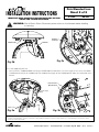
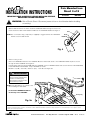
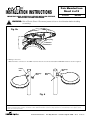
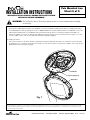
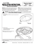
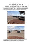
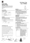
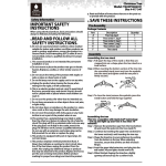
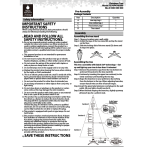
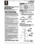
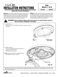
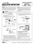
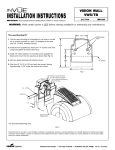
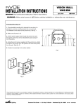
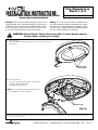
TM
Pole Mounted Icon
INSTALLATION INSTRUCTIONS
IMPORTANT: READ CAREFULLY BEFORE INSTALLING FIXTURE.
RETAIN FOR FUTURE REFERENCE.
General: Upon receipt of fixture thoroughly inspect for any
freight damage, which should be brought to the attention of
the delivery carrier. Compare the catalog description listed
on the packing slip with the fixture label on the housing to
assure you have received the correct merchandise.
Sheet 1 of 5
3/11/04
IMI-593
Safety: This fixture must be wired in accordance with
the national electrical code and applicable local codes
and ordinance. Proper grounding is required to insure
personal safety. Carefully observe grounding procedure.
All work should be done by an electrician.
WARNING: Risk of Electric Shock. Disconnect power at circuit breaker panel or
fuse box before installing or servicing.
1. Open the Door Press both BUTTON LATCHES at the same time and open the door.
See Figure 1.
Fig. 1
Button Latches
Push to Open
2. Reflector Removal Press the two REFLECTOR TABS outward and
swing the REFLECTOR down.
See Figure 2a and Figure 2b.
NOTE: Disconnect REFLECTOR CONNECTOR from
the HOUSING as shown in Figure 2c.
Reflector Tabs
Fig. 2a
These instructions do not claim to cover all details or variations in the equipment, procedure, or process described, nor to provide directions for meeting every possible
contingency during installation, operation or maintenance. When additional information is desired to satisfy a problem not covered sufficiently for user’s purpose, please
contact your nearest representative.
Customer First Center • 1121 Hwy 74 South • Peachtree City, GA 30269
IMI-593
AVU040206
TM
Pole Mounted Icon
INSTALLATION INSTRUCTIONS
IMPORTANT: READ CAREFULLY BEFORE INSTALLING FIXTURE.
RETAIN FOR FUTURE REFERENCE.
Sheet 2 of 5
3/11/04
IMI-593
WARNING: Risk of Electric Shock. Disconnect power at fuse or circuit breaker before installing
or servicing.
Reflector
Connector
Reflector Tabs
Reflector
Fig. 2c
Fig. 2b
3. Power Supply Tray Removal Unscrew the two THUMB SCREWS and swing the POWER SUPPLY TRAY down as shown in Figure 3a. Disconnect the POWER
CONNECTOR and the OPTIC CONNECTOR from HOUSING. See Figure 3b. The POWER SUPPLY TRAY can now be lifted off the
bracket.
Power Connector
Optic Connector
Power Supply
Tray
Thumb Screws
Fig. 3a
Fig. 3b
These instructions do not claim to cover all details or variations in the equipment, procedure, or process described, nor to provide directions for meeting every possible
contingency during installation, operation or maintenance. When additional information is desired to satisfy a problem not covered sufficiently for user’s purpose, please
contact your nearest representative.
Customer First Center • 1121 Hwy 74 South • Peachtree City, GA 30269
IMI-593
AVU040206
TM
Pole Mounted Icon
INSTALLATION INSTRUCTIONS
Sheet 3 of 5
3/11/04
IMPORTANT: READ CAREFULLY BEFORE INSTALLING FIXTURE.
RETAIN FOR FUTURE REFERENCE.
IMI-593
WARNING: Risk of Electric Shock. Disconnect power at fuse or circuit breaker before installing
or servicing.
4. Attach Arm to Pole Slide the NUT PLATE into the POLE. Install the THREADED RODS through the holes in the
POLE and into the NUT PLATE. Slide the ARM over the THREADED RODS. See Figure 4.
Arm
NOTE: Use of a thread locking compound (not supplied) is suggested where the THREADED
RODS contact the NUT PLATE.
Rods
Nut Plate
Pole
Fig. 4
5. Attach Housing to Arm Remove the WIREWAY PLUG from the HOUSING. Move the fixture leads aside so the THREADED RODS may be accessed
through the fixture HOUSING. See Figure 5a.
Feed the fixture wires through the ARM. Slide the HOUSING over the THREADED RODS and secure it with the PLAIN WASHERS,
LOCK WASHERS and HEX NUTS. Torque HEX NUTS as follows:
Medium Icon (ICM) - 450 in-lbs., Small Icon (ICS) - 130 in-lbs. See Figure 5b.
WARNING
Risk of Personal Injury
Fixture may become damaged and/or
unstable if not installed properly
Tighten all fixture components to their
recommended torque values
NOTE: It may be helpful to use a deep socket
when installing the HEX NUTS.
Re-install the WIREWAY PLUG into
the wireway in the HOUSING.
Wireway Plug
Fig. 5a
These instructions do not claim to cover all details or variations in the equipment, procedure, or process described, nor to provide directions for meeting every possible
contingency during installation, operation or maintenance. When additional information is desired to satisfy a problem not covered sufficiently for user’s purpose, please
contact your nearest representative.
Customer First Center • 1121 Hwy 74 South • Peachtree City, GA 30269
IMI-593
AVU040206
TM
Pole Mounted Icon
INSTALLATION INSTRUCTIONS
IMPORTANT: READ CAREFULLY BEFORE INSTALLING FIXTURE.
RETAIN FOR FUTURE REFERENCE.
Sheet 4 of 5
3/11/04
IMI-593
WARNING: Risk of Electric Shock. Disconnect power at fuse or circuit breaker before installing
or servicing.
Fig. 5b
Wireway Plug
Nut
Lock Washer
Plain Washer
6. Making ConnectionsMake the fixture connections in the ARM. Insert the wires into the arm and reinstall the WIREWAY DOOR as shown in Figure 6.
Linear
Arm
Upsweep
Arm
Wireway
Door
Wireway
Door
Fig. 6
These instructions do not claim to cover all details or variations in the equipment, procedure, or process described, nor to provide directions for meeting every possible
contingency during installation, operation or maintenance. When additional information is desired to satisfy a problem not covered sufficiently for user’s purpose, please
contact your nearest representative.
Customer First Center • 1121 Hwy 74 South • Peachtree City, GA 30269
IMI-593
AVU040206
TM
Pole Mounted Icon
INSTALLATION INSTRUCTIONS
IMPORTANT: READ CAREFULLY BEFORE INSTALLING FIXTURE.
RETAIN FOR FUTURE REFERENCE.
Sheet 5 of 5
3/11/04
IMI-593
WARNING: Risk of Electric Shock. Disconnect power at fuse or circuit breaker before installing
or servicing.
7. Buttoning Up Re-install the POWER SUPPLY TRAY to the HOUSING. Connect the POWER CONNECTOR and OPTIC CONNECTOR. Swing
the POWER SUPPLY TRAY up and tighten the two THUMB SCREWS. Re-install the REFLECTOR to the HOUSING. Connect the
REFLECTOR CONNECTOR to the HOUSING. Swing the REFLECTOR up until it is secured by the REFLECTOR TABS. You
will hear an audible “click” when the REFLECTOR TABS have properly engaged. Close the fixture DOOR. See Figure 7. You will
hear two audible “clicks” when the two BUTTON LATCHES are properly engaged.
Re-lamping the Fixture
Disconnect the power to the fixture. Open the DOOR by pressing both BUTTON LATCHES at the same time. Remove the lamp
by grasping it close to the base and install the new lamp. Close the fixture DOOR. You will hear two audible “clicks” when the two
BUTTON LATCHES are properly engaged.
Reflector
Power Supply Tray
Outer Door
Fig. 7
These instructions do not claim to cover all details or variations in the equipment, procedure, or process described, nor to provide directions for meeting every possible
contingency during installation, operation or maintenance. When additional information is desired to satisfy a problem not covered sufficiently for user’s purpose, please
contact your nearest representative.
Customer First Center • 1121 Hwy 74 South • Peachtree City, GA 30269
IMI-593
AVU040206