1
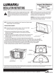
Small Falcon
INSTALLATION INSTRUCTIONS
IMPORTANT: READ CAREFULLY BEFORE INSTALLING LUMINAIRE.
RETAIN FOR FUTURE REFERENCE.
General: Upon receipt of luminaire thoroughly inspect for
any freight damage, which should be brought to the
attention of the delivery carrier. Compare the catalog
description listed on the packing slip with the luminaire label
on the housing to assure you have received the correct
merchandise.
Sheet 1 of 7
1/26/05
IMI-623
Safety: This luminaire must be wired in accordance with
the national electrical code and applicable local codes
and ordinance. Proper grounding is required to insure
personal safety. Carefully observe grounding procedure.
All work should be done by a qualified electrician.
WARNING: Risk of Electric Shock. Disconnect power at fuse or circuit breaker before installing
or servicing.
FAILURE TO FOLLOW INSTRUCTIONS MAY RESULT IN SERIOUS INJURY OR DEATH.
IMPORTANT: READ CAREFULLY BEFORE INSTALLING LUMINAIRE. RETAIN FOR FUTURE USE.
WARNING: Risk of Burn. Disconnect power and allow fixture to cool before changing lamp or
handling fixture.
APPLICATIONS:
WARNING: Risk of Fire. These luminaires are intended for outdoor lighting service and should
not be used in areas of limited ventilation or in high ambient temperature enclosures.
WARNING: Risk of Fire. Supply conductors (power wires) connecting the fixture must be rated
minimum 60°C. If uncertain, consult an electrician.
• Suitable for Wet & Damp Location.
• Use lamp type suitable for this luminaire. Consult re-lamp label and lamp instructions for details.
These instructions do not claim to cover all details or variations in the equipment, procedure, or process described, nor to provide directions for meeting every possible
contingency during installation, operation or maintenance. When additional information is desired to satisfy a problem not covered sufficiently for user’s purpose, please
contact your nearest representative.
Customer First Center • 1121 Hwy 74 South • Peachtree City, GA 30269
IMI-623
ACF050370
Small falcon
INSTALLATION INSTRUCTIONS
IMPORTANT: READ CAREFULLY BEFORE INSTALLING LUMINAIRE.
RETAIN FOR FUTURE REFERENCE.
Sheet 2 of 7
1/26/05
IMI-623
WARNING: Risk of Electric Shock. Disconnect power at fuse or circuit breaker before installing
or servicing.
INSTALLATION:
Mounting: (Illustrations 1, 2, and 3)
Water tight
seal
at cord
Water
tight
seal
at cord
entry providd by others.
entry provided by others.
KNUCKLE MOUNT
ILLUSTRATION 1
TRUNION (YOKE) MOUNT
ILLUSTRATION 2
ILLUSTRATION 3
Knuckle Mount - Illustration 1
This luminaire is equipped with an adjustable knuckle which can be mounted directly to the 1/2" NPS access hole in the coverplate
of the junction box. Route luminaire leads through the mounting hole on the coverplate. Secure coverplate to knuckle by screwing
the coverplate onto the knuckle. Do not tighten locknut at this time (see aiming). NOTE: Mounting the coverplate to the junction
box and then screwing the knuckle of the luminaire into the coverplate can result in twisting the wires, causing
connections to break and creating a shock hazard when the power is turned on. Use wire nuts or other approved
connectors to connect the black luminaire lead to the black supply lead, the white luminaire lead to the white supply lead and the
bare ground luminaire lead to a suitable ground. Push wires into junction box and install the coverplate (with luminaire attached) to
the junction box.
WARNING: Risk of fire and/or electric shock. Failure to follow the above mounting instructions may result in
personal injury and/or property damage.
Trunion (Yoke) Mount - Illustration 2
This luminaire is provided with a trunion (yoke) which can be mounted directly on a flat surface. Use wire nuts or other approved
connectors to connect the black lead from the cord to the black supply lead, the white lead from the cord to the white supply lead
and the green lead from the cord to a suitable ground.
WARNING: Risk of fire and/or electric shock. Failure to follow the above mounting instructions may result in
personal injury and/or property damage.
Illustration 3
WARNING: Risk of fire and/or electric shock. Trunion luminaire mounting orientation as shown in
Illustration 3 is not allowed. Water entry may result causing damage to internal electrical
components.
Proper trunion luminaire mounting orientation will result in a horizontal lamp orientation.
These instructions do not claim to cover all details or variations in the equipment, procedure, or process described, nor to provide directions for meeting every possible
contingency during installation, operation or maintenance. When additional information is desired to satisfy a problem not covered sufficiently for user’s purpose, please
contact your nearest representative.
Customer First Center • 1121 Hwy 74 South • Peachtree City, GA 30269
IMI-623
ACF050370
Small falcon
INSTALLATION INSTRUCTIONS
IMPORTANT: READ CAREFULLY BEFORE INSTALLING LUMINAIRE.
RETAIN FOR FUTURE REFERENCE.
Sheet 3 of 7
1/26/05
IMI-623
WARNING: Risk of Electric Shock. Disconnect power at fuse or circuit breaker before installing
or servicing.
Voltage Wiring: (Illustration 4)
WARNING: Risk of Electric Shock. Disconnect power at fuse or circuit breaker before installing or servicing.
Ballast
BALLAST
Insulated Voltage
INSULATED
VOLTAGE
Leads
LEADS
Wire
WIRENut
NUT
White
WHITE
WHITE
White
Ground
GROUND
NOTE: Luminaire shown with lamp and
reflector removed.
White
WHITE
GG
RrEeEen
N
k
aCcK
BLBAl
Black
BLACK
ILLUSTRATION 4
Some luminaire ballasts are provided with multiple voltage options. The ballast voltage must be properly selected to
match the incoming supply voltage. If it is necessary to change the ballast voltage, remove the wire nut from the black
supply wire. Remove the ballast voltage lead wire and insulate the bare end according to the local electric code. Select
the desired ballast voltage lead wire. Remove the insulation and connect the lead wire to the black supply wire using the
wire nut previously removed. Insure that all wire connections are properly secure and insulated according to the local
electric code.
CAUTION: The ballast voltage must be properly selected to match the incoming supply voltage or damage to the
ballast will occur
These instructions do not claim to cover all details or variations in the equipment, procedure, or process described, nor to provide directions for meeting every possible
contingency during installation, operation or maintenance. When additional information is desired to satisfy a problem not covered sufficiently for user’s purpose, please
contact your nearest representative.
Customer First Center • 1121 Hwy 74 South • Peachtree City, GA 30269
IMI-623
ACF050370
Small falcon
INSTALLATION INSTRUCTIONS
Sheet 4 of 7
1/26/05
IMPORTANT: READ CAREFULLY BEFORE INSTALLING LUMINAIRE.
RETAIN FOR FUTURE REFERENCE.
IMI-623
WARNING: Risk of Electric Shock. Disconnect power at fuse or circuit breaker before installing
or servicing.
Trunion Luminaire Vent Plug: (Illustration 5 and 6)
Remove
Vent Plug
Remove
Vent Plug
ILLUSTRATION 6
ILLUSTRATION 5
NOTE: When gound mounting a trunion luminaire
this vent plug must be removed
NOTE: When overhead mounting a trunnion
luminaire this vent plug must be removed.
CAUTION: Failure to remove the proper trunnion luminaire vent plug as illustrated above may result in water entry causing
damage to internal electrical components.
NOTE: DO NOT REMOVE ANY VENT PLUG FROM A KNUCKLE LUMINAIRE.
AIMING: (Illustration 7 and 8)
To aim knuckle
To aim knuckle
luminaire
luminaire --loosen
loosen
screw,
screw, rotate
rotate
luminaire
luminaire
to
desired
aiming
to
desired
aiming
and securly
and
securly
tighen
screw tighten screw.
KNUCKLE AIMING
ILLUSTRATION 7
To aim trunion
To aim trunnion
luminaire
- loosen
luminaire
four bolts,
rotate
--loosen
four
bolts,
rotate
luminaire
to
luminaire to
desired
aiming
desired
aiming
and
securely
and securely
tighten four
tighten four
bolts bolts.
TRUNION AIMING
ILLUSTRATION 8
These instructions do not claim to cover all details or variations in the equipment, procedure, or process described, nor to provide directions for meeting every possible
contingency during installation, operation or maintenance. When additional information is desired to satisfy a problem not covered sufficiently for user’s purpose, please
contact your nearest representative.
Customer First Center • 1121 Hwy 74 South • Peachtree City, GA 30269
IMI-623
ACF050370
Small falcon
INSTALLATION INSTRUCTIONS
IMPORTANT: READ CAREFULLY BEFORE INSTALLING FIXTURE.
RETAIN FOR FUTURE REFERENCE.
Sheet 5 of 7
1/26/05
IMI-623
WARNING: Risk of Electric Shock. Disconnect power at fuse or circuit breaker before installing
or servicing.
Door Latch: (Illustration 9)
To open door,
lift latch
To open door, lift
andand
rotate
latch
rotate
away
fromfrom
door.
away
door
6-32 door
latchlatch
securing
6-32
door
screw provided (not factory
securing
screw
installed). Customer may
provided(not
factory
replace with a tamper
installed).
resistant screwcustomer
of their
choosing
(max. length
1/4”)
may
replace
with
a
or order Cat. No. SF/TR if
tamper
resistant
desired.
screw of their
choosing or order
Cat. No. SF/TRS if
desired.
ILLUSTRATION 9
Relamping: (Illustration 10)
WARNING: Risk of Burn. Disconnect power and allow fixture to cool before changing lamp or handling fixture.
Rotate door to open
for relamping and
maintenance.
ILLUSTRATION 10
When re-lamping, turn power off and allow the luminaire to cool. Pror to installing the lamp, check that the lamp is of proper type and
wattage. Screw the lamp securely into socket, back the lamp out one to two turns, then screw the lamp back in, making sure it is
secured. This properly seats the lamp in socket.
Cleaning:
WARNING: Risk of Electric Shock. Disconnect power at fuse or circuit breaker before servicing.
WARNING: Risk of Burn. Disconnect power and allow fixture to cool before handling fixture.
The reflector and door glass may be cleaned with any suitable, non-abrasive glass cleaning solution, soap or detergent and rinsed
with clean water.
These instructions do not claim to cover all details or variations in the equipment, procedure, or process described, nor to provide directions for meeting every possible
contingency during installation, operation or maintenance. When additional information is desired to satisfy a problem not covered sufficiently for user’s purpose, please
contact your nearest representative.
Customer First Center • 1121 Hwy 74 South • Peachtree City, GA 30269
IMI-623
ACF050370
Small falcon
INSTALLATION INSTRUCTIONS
Sheet 6 of 7
IMPORTANT: READ CAREFULLY BEFORE INSTALLING LUMINAIRE.
RETAIN FOR FUTURE REFERENCE.
1/26/05
IMI-623
WARNING: Risk of Electric Shock. Disconnect power at fuse or circuit breaker before installing
or servicing.
Accessory Installation:
TOP VISOR
ILLUSTRATION 11
VANDAL SHIELD
ILLUSTRATION 12
Locate top visor and install (2) 8-32
screws provided. Tighten screws securely.
Locate vandal shield and install (3) 8-32
screws provied. Tighten screws securely.
Hooks
Hooks
Locate (2) wire guard hooks into slots in
door frame. Apply pressure to (2) opposite
hooks and rotate wire guard into position.
Release hooks insuring secure engagement
to door frame.
Slot in
Door
Frame
Slot in
Door
Frame
WIRE GUARD
ILLUSTRATION 13
These instructions do not claim to cover all details or variations in the equipment, procedure, or process described, nor to provide directions for meeting every possible
contingency during installation, operation or maintenance. When additional information is desired to satisfy a problem not covered sufficiently for user’s purpose, please
contact your nearest representative.
Customer First Center • 1121 Hwy 74 South • Peachtree City, GA 30269
IMI-623
ACF050370
Customer First Center • 1121 Hwy 74 South • Peachtree City, GA 30269
IMI-623
ACF050370
Center
Punch
Here
(See Step 3)
1/26/05
IMI-623
Sheet 7 of 7
Small Falcon
These instructions do not claim to cover all details or variations in the equipment, procedure, or process described, nor to provide directions for meeting every possible
contingency during installation, operation or maintenance. When additional information is desired to satisfy a problem not covered sufficiently for user’s purpose, please contact
your nearest representative.
may result in personal injury and/or property damage.
WARNING: Risk of fire and/or electric shock. Failure to follow the above instructions
7. Install Cat. No. PE/MT using instruction sheet provided with the
Photoelectric Control.
6. Remove all burrs at hole both inside and outside of luminaire.
Remove all metal chips from inside of luminaire.
5. Drill a 27/32 (.843) inch diameter hole at center punch location.
Use several smaller drills first or use a step drill for this process.
4. Remove template and any electrical components and/or wiring
located in the areas inside the luminaire where the hole is to be
drilled.
3. Place center punch at target point and procede to center punch
the top surface of the luminaire.
2. Open luminaire door, rotate latch forward and align this template
on top surface of luminaire.
1. Use scissors to carefully cut this template from this sheet.
Instructions:
WARNING: Risk of Electric Shock. Disconnect power at fuse or circuit breaker before using this template.
NOTE: FOR USE ONLY WHEN INSTALLING CAT. NO. PE/MT PHOTOELECTRIC CONTROL
SMALL FALCON DRILL TEMPLATE