1
Revision History
Date
Revision
Description
Jul 22, 2003
00
Released per ECO 03-188
Sep 11, 2003
01
Updated per ECO 03-225
Nov 10, 2003
02
Updated per ECO 03-269
System Configuration
When contacting your dealer or Avidyne technical support, and when
logging onto www.myavidyne.com for the first time, please have your
FlightMax EX5000 serial number and Subscriber Communicator
serial number available. (Record these below for future reference.)
FlightMax EX5000 S/N: _________________
Datalink Subscriber Communicator S/N: _________________
600-00101-000, Rev 02
-i-
FlightMax EX5000
Page Intentionally Left Blank.
FlightMax EX5000
-ii-
600-00101-000, Rev 02
Table of Contents
Introduction . . . . . . . . . . . . . . . . . . . . . . . . . . . . . . . . . . . . . .2
Operation . . . . . . . . . . . . . . . . . . . . . . . . . . . . . . . . . . . . . . . .3
Map Page . . . . . . . . . . . . . . . . . . . . . . . . . . . . . . . . . . . . . . . .4
Controls . . . . . . . . . . . . . . . . . . . . . . . . . . . . . . . . . . . . . . .4
Symbology . . . . . . . . . . . . . . . . . . . . . . . . . . . . . . . . . . . . .6
Map Orientation Control . . . . . . . . . . . . . . . . . . . . . . . . . .7
Using Datalink . . . . . . . . . . . . . . . . . . . . . . . . . . . . . . . . . .8
Trip Page . . . . . . . . . . . . . . . . . . . . . . . . . . . . . . . . . . . . . . . .10
Nearest Page . . . . . . . . . . . . . . . . . . . . . . . . . . . . . . . . . . . . .12
Engine Instruments . . . . . . . . . . . . . . . . . . . . . . . . . . . . . . .14
Gauges . . . . . . . . . . . . . . . . . . . . . . . . . . . . . . . . . . . . . .15
Fuel Usage . . . . . . . . . . . . . . . . . . . . . . . . . . . . . . . . . . .16
Temperatures . . . . . . . . . . . . . . . . . . . . . . . . . . . . . . . . . .17
Lean Assist . . . . . . . . . . . . . . . . . . . . . . . . . . . . . . . . . . .18
Data Blocks . . . . . . . . . . . . . . . . . . . . . . . . . . . . . . . . . . .19
Data Log . . . . . . . . . . . . . . . . . . . . . . . . . . . . . . . . . . . . .21
Setup Pages . . . . . . . . . . . . . . . . . . . . . . . . . . . . . . . . . . . . .22
Main . . . . . . . . . . . . . . . . . . . . . . . . . . . . . . . . . . . . . . . . .22
Airport Filter . . . . . . . . . . . . . . . . . . . . . . . . . . . . . . . . . . .23
Declutter . . . . . . . . . . . . . . . . . . . . . . . . . . . . . . . . . . . . .24
Data Block Edit . . . . . . . . . . . . . . . . . . . . . . . . . . . . . . . .25
System Time . . . . . . . . . . . . . . . . . . . . . . . . . . . . . . . . . .26
Data Link . . . . . . . . . . . . . . . . . . . . . . . . . . . . . . . . . . . . .27
Traffic Mode . . . . . . . . . . . . . . . . . . . . . . . . . . . . . . . . . . . . .28
Database Updates . . . . . . . . . . . . . . . . . . . . . . . . . . . . . . . .29
Appendix . . . . . . . . . . . . . . . . . . . . . . . . . . . . . . . . . . . . . . . .30
Tables . . . . . . . . . . . . . . . . . . . . . . . . . . . . . . . . . . . . . . .30
Data Base Update Procedures . . . . . . . . . . . . . . . . . . . .41
Data Base Region Map . . . . . . . . . . . . . . . . . . . . . . . . . .41
Failure Indications . . . . . . . . . . . . . . . . . . . . . . . . . . . . . .42
An approved Flight Manual Supplement (FMS) will be providd
by your installer. The FMS contains information specific to your
installation. It contains any operating limitations that may
apply.
600-00101-000, Rev 02
-1-
FlightMax EX5000
Introduction
The FlightMax EX5000 Multi-Function Displays (MFD) provide a pictorial view of
your flight situation based on input from your GPS navigator. It utilizes on-board
database information for mapping off-route navigation data such as nearby airports,
VORs, NDBs, special-use and restricted airspace, etc., as well as terrain, interstate
highways, bodies of water, and obstacles.
The EX5000 uses RS-232 to interface to external sensors such as GPS, Goodrich
WX-500 Stormscope Sensor, and Ryan TCAD Traffic Sensor, if installed. The
EX5000 additionally offers ARINC 429 data bus capability. When interfaced via
ARINC 429 to a Garmin GNS 430/420-series GPS, the EX5000 will display the curved
paths associated with instrument approaches including DME arcs, holds, and
procedure turns. The EX5000 will also provide traffic display capability when
interfaced with the Goodrich Skywatch® traffic sensor, if installed.
2
1
3
4
7
5
6
4
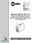
The controls on the bezel of the FlightMax EX5000 are placed to allow you quick and
intuitive access to the information you need, when you need it.
FlightMax EX5000
-2-
600-00101-000, Rev 02
Operation
General
The EX5000 startup is automatic once power is applied. The system performs a brief
hardware self-test, then systematically initializes its functions. After the system has
been initialized (less than a minute after power-on), the title screen appears on the
system page. Database currency information is also presented. It is here that the pilot
is warned of any expired databases.
When the MFD is ready for use, the message “Press any bezel key to continue” is displayed.
Operational Controls
1. PhotoCell Light Sensor - Automatically compensates display brightness for
varying lighting conditions.
2. Brightness Control - Manually adjusts display brightness level.
3. Data Port - Provides a front panel access point for loading database updates and
downloading recorded engine data.
4. Buttons - Used to select modes or change the display as indicated. Active when
label appears on the screen adjacent to the key.
5. Page Control - Left knob provides quick access to the various MFD pages. The current page is highlighted in lower left corner of screen.
6. Range & Cursor Control - Right knob controls the Map’s range. When other pages
are selected, the right knob provides item selection control.
7. Message Bar - The message bar is used to keep the pilot informed about critical and
advisory information from the MFD. When information needs to be conveyed the
message bar appears as the lowest right button.
The message bar can display only one message at a time. If more than one message
is available, the message bar will display the highest priority message on top. The key
associated with the Message must be depressed to clear messages and view those
underneath.
600-00101-000, Rev 02
-3-
FlightMax EX5000
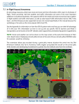
Map Page - Controls
Line select keys on the left side of the bezel provide access to sensor modes. Line
select keys on the right side of the bezel access the mapping functions, and control
how the Map is viewed.
1
2
3
1. Sensor Functions - Control overlay and modes of available sensors. Buttons are
only displayed for those sensors that are installed in the aircraft.
Traffic button with TAS (SkyWatch or BendixKing) cycles through traffic sensor
modes and overlay in the following order:
Above ->Normal ->Below ->Unlimited (UNLIMTD) ->Traffic Overlay Off (DSPLY OFF)
Traffic button, with Ryan TCAD, cycles through traffic sensor modes and overlays
based on the phase of flight as calculated from the TCAD. The modes are:
Ground, Terminal, Standard, Enroute, Unlimited, Approach, Departure and Display
off.
Intruders are displayed as they are received from and identified by the sensor. The
threat level assigned to an intruder is the threat level specified by the sensor when
it transmits the intruder data. Threat data, range, bearing, altitude, ID and closing
direction are defined by the sensor and the type of sensor used in your system.
FlightMax EX5000
-4-
600-00101-000, Rev 02
Map Page - Controls
Lightning button cycles through lightning sensor modes and overlay in the
following order: Strike ->Cell ->Lightning Overlay Off (DSPLY OFF)
The lightning sensor maps thunderstorm activity by monitoring electrical discharge
activity within a 200-mile radius of the aircraft. Lightning strikes less than 25NM
distant are not displayed if the display range is set to less than 25NM. If the display
range is set to greater than 25NM, all lightning strikes will be displayed.
Clear Strikes button removes lightning symbols to allow for the refresh of
lightning data.
Weather button cycles through Datalink weather modes and overlay based on the
Datalink data requested from the Datalink Setup Page. With all data requested,
the order is: ALL (Nexrad, METARS and Airmets) ->REPORTS (METARS and
Airmets) -> NEXRAD -> Datalink Weather Display Off.
2. Map Functions - Control basic look of the map in terms of orientation, number of
elements, and base map.
View line select key orients the map for either Track/Heading Up or North Up.
FORWARD view orients the map with Track/Heading Up and the aircraft symbol at
the bottom of the screen. CENTER view orients the map with Track/Heading Up
and the aircraft symbol centered on the screen. NORTH UP orients the map with
North Up.
Declutter line select key allows you to quickly choose from four levels of database
Nav Map detail from most to least:
Base Map line select key selects from three levels of map detail, starting with
contoured terrain with interstate highways, water base map, and political boundaries. Pressing the key removes contoured terrain with Interstates, while leaving
water and political boundary references. Push again to view the flight plan on a
traditional EFIS-style black background.
3. Range Control - Controls the map’s range and allows you to range down to 1NM
scale and out to 1500NM scale. The nineteen selectable ranges are 1, 2, 5, 10,
15, 20, 30, 40, 50, 75, 100, 150, 200, 300, 400, 500, 750, 1000, 1500.
NOTE: Terrain base map is automatically removed and Nav database information
is fully decluttered at 750NM and higher ranges.
600-00101-000, Rev 02
-5-
FlightMax EX5000
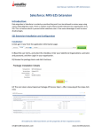
Map Page - Symbology
The MFD’s map presentation depicts your aircraft’s position in relation to flight plan,
nearby airports, terrain, traffic, lightning, weather, special use airspace and other
navaids.
3
1
5
2
6
10
8
12
4
9
11
7
1. Data Blocks (Left & Right) - View navigation and engine data in data blocks in the
upper corners of the display. See Data Block Edit (page 25) for options.
2. Sensor Status Box - Displays Nexrad data status and age, and the status of traffic
and lightning sensors, if installed.
3. Heading/Track Indicator - Three triangles around the compass rose provide actual
track, desired track, and heading indications. The H/T Block provides digital readout of
the current heading, or actual track. Map orientation is indicated in the triangle to the
right of the H/T Block.
Desired Track
Track Up
H/T Block
Heading Up
Actual Track
Heading
North Up
4. Obstacles - The MFD’s database contains towers and other obstacles greater than
200 feet AGL. Obstacles can be displayed with MSL altitude label. Symbols for
Obstacles:
1000’ AGL or higher
200’ AGL to <1000’AGL
Groups of obstacles
within 1NM of each other
FlightMax EX5000
Groups of obstacles 1000’ AGL or
higher and within 1NM of each other.
-6-
600-00101-000, Rev 02
Map Page - Symbology
5. Compass Rose/Range Ring - Displays a 360-degree or 120-degree compass
circle or arc and also indicates current range setting. The range number is the
distance from the airplane symbol to the compass arc.
6. Terrain Scale - Shows highest and lowest limits of terrain in displayed area. Legend
colors in between these numerics represent terrain elevations. Blue obstacle clearance
number shows the top of the highest obstacle, when greater than the highest displayed
terrain. Terrain data is not displayed when your aircraft’s latitude is greater than 75
degrees (north or south).
7. Special Use Airspace - The MFD uses several different line styles to convey special
use and class airspaces. Class B is solid blue line, Class C is solid magenta line.
Class D is dashed blue line, MOA, Warning, and Alert areas are solid yellow lines, and
restricted and prohibited areas are solid red lines. Reference Table 5 and associated
note (Page 33).
8. Airport Runway Diagrams - Runway layouts of your destination airport and nearby
airports are displayed. As you range in, the scaled runway diagram with heading
labels shows your exact location in proximity to the field.
9. Flight Plan - The active flight plan from the GPS is displayed on the map. The
current leg is displayed in magenta and all remaining legs are shown in white.
When you select an approach procedure on the Garmin 430, all approach segments including holds, DME arcs, procedure turns, etc., are shown.
NOTE: The Garmin GNS 430/GNC 420 does not differentiate curved flight path segmentsfrom straight segments when interfaced with the MFD via an RS232 interface. Therefore,
the MFD will connect the beginning and end waypoints of a curved segment, such as a DME
arc, with a straight line. Under these circumstances, the straight line must be ignored.
Approach procedures should be flown using the GNS 430/GNC 420 navigator’s CDI as the
primary reference. Consult your avionics installation facility to determine if your MFD is
interfaced to the GNS 430/GNC420 via ARINC 429 or RS232.
10. Traffic Indications - Shows traffic symbol relative to current position and
includes relative altitude (when available) with respect to airplane symbol.
See traffic sensor user’s manual for further details.
11. Lightning Indications - Shows lightning strikes geographically referenced if
configured. Strikes represented by yellow “X” in Strike Mode, and by
yellow “+” in Cell Mode. Lightning strikes are displayed for three minutes.
12. Airplane Symbol - Shows the position of your aircraft in relation to the
moving map and the selected view.
Map Orientation Control
The pilot can control the orientation of the map and sensor data displayed on the
MFD with the Map View button. MFD traffic and lightning symbols are positioned
relative to the aircraft symbol nose. When the Map View is North-Up extra pilot effort
may be needed to locate traffic outside the aircraft. Set Map View to Center or
Forward to display this data consistent with typical dedicated traffic and lightning
sensor displays.
600-00101-000, Rev 02
-7-
FlightMax EX5000
Using Datalink
Your EX5000 comes equipped with an integrated datalink function that allows you to
stay completely tuned in to the current weather, SUA, and TFR conditions along your
route of flight. Since this function is completely integrated, there is nothing "special" or
new that you need to learn to make it work for you.
You will need to log on to www.myavidyne.com and follow the simple account setup
instructions in order to establish an Avidyne datalink account. Be sure to have your
datalink subscriber communicator (SC) serial number handy. You will need it to open
your account. You can view your SC s/n on the EX5000 Datalink Setup Page
(Figure 11). Once your account is activated, you may immediately begin enjoying the
advantages of the EX5000’s satellite-based datalink capability. In addition, your
www.myavidyne.com datalink account provides you with access to your billing and usage
statements, as well as providing pre-flight weather links and planning tools. You can set
your datalink user preferences online prior to your flight, and they will be downlinked to
your EX5000 via satellite the next time you fly.
When you power the EX5000 up, it will immediately begin sending position data to tell the
satellite network where you are and that you are about to begin a flight. Weather data will
begin transferring to your airplane based upon your user preferences. No action is required
to begin receiving weather (You will have to pull your airplane out of the hangar so that the
satellite receiver can interrogate and locate a satellite).
Upon entry of a flight plan into your primary GPS receiver, your EX5000 will
automatically download the weather for your route of flight without any additional action
required. Additional updates will be provided while enroute based upon the update rate
that you have selected online or on the EX5000’s datalink setup page.
Figure 11 - Datalink Setup Page
FlightMax EX5000
-8-
600-00101-000, Rev 02
Using Datalink
The Weather Overlay button allows you to add Nexrad Graphical METARs and Airmets
weather images onto the map display.
1. NEXRAD data is displayed in a four-color format consistent with weather radar
data. The NEXRAD age is displayed in the sensor status box. The displayed age is
calculated based on the time the national NEXRAD composite image is created. The
actual radar data may be slightly older than the displayed NEXRAD age. A legend for
the NEXRAD display is available on the trip page.
3
2
1
Figure 12 - Map with NEXRAD & Graphical METARs
2. Graphical METARS are displayed as small upright flags. These offer you a chance to
look at the "bigger picture" for weather along your route of flight. A legend for the
graphical METARS is available on the Trip Page.
CAUTION: Datalink weather should only be used for strategic planning purposes. Datalink weather should not be used for tactical weather avoidance.
Local conditions may have changed since your last weather update.
3. Airmet/Sigmet data is overlaid with lines that alternate between single and triple
thick. The thick side of the line indicates the inside of the affected region. The
regions are labeled according to the type of Airmet/Sigmet, and the label is located in
the interior of the depicted region. (see table xxx)
NOTE: The National Weather Service only provides NEXRAD for the Continental United
States (CONUS). The EX5000 will not depict NEXRAD images for areas outside of
CONUS.
The boundary of the available weather coverage area is shown by hash marks. The
intent of the datalink weather boundary is to clearly show when there is actual weather
in the area, versus when there may be weather in a given area but it is not displayed.
If you would like to expand the amount of data displayed (and therefore move the
boundary farther from your flight plan) you can do this on the Datalink Setup Page or
at www.myavidyne.com.
600-00101-000, Rev 02
-9-
FlightMax EX5000
Trip Page
The Trip Page is continuously updated during flight. The distance and the time
values are updated with each new positive fix from the GPS. The route legs
advance with each waypoint message. Turning the left knob one detent to the
right from the Map page brings up the Trip Page, which shows the remaining legs
in the current flight plan and other data being received by the MFD from the GPS.
If the flight plan doesn’t fit on the screen, an ellipse (...) is shown in the next to
last line. The destination is always displayed, on the last line. A “No Flightplan
Available” message is displayed if there is no flight plan entered or if the GPS has
failed.
1
3
4
2
9
5
7
6
8
1. Current ground speed and track
2. Flight Plan information from your GPS. Active waypoint is shown in magenta.
Displayed data:
WPT - Waypoint identifier as received from the GPS
BRG - Bearing to current waypoint
DTK - Desired track to waypoint
DIST (NM) - Cumulative great circle distance of each flight plan leg
ETE - Cumulative estimated time en route to waypoint in H:MM format
for each flight plan leg at current ground speed.
ETA - Estimated time of arrival to waypoint in HH:MM formatted for
airplane local time.
Fuel Remaining - Available with Engine and Fuel Monitor function.
Displays remaining fuel at each waypoint in gallons.
Nrst METAR - Available with Datalink enabled. Displays Graphical METAR
and reporting point identifier.
When conducting a Direct To flight plan, the MFD will supply METAR information for
several intermediate reporting stations along your route. These will be shown as
blank lines on the flight plan list, with "Wx" in the first column, and the METAR flag
in its normal position in the right column. Selecting one of the intermediate points
will display the text METAR on the lower half of the screen. The intermediate
METAR stations will be removed from the list as you pass them during your flight.
FlightMax EX5000
-10-
600-00101-000, Rev 02
Trip Page
NOTE: When the MFD is interfaced to a Garmin GNS-430/GNC-420 via
RS-232, the GPS may send duplicate waypoints while in approach mode. These duplicate
waypoints may affect the distance and time readings on the trip page. Approach procedures should be flown using the GPS as the primary source of navigation information.
Consult your avionics installation facility to determine if your MFD is interfaced to the
Garmin GNS-430/GNC-420 via ARINC 429 or RS-232.
3. Course Deviation Indicator (CDI) - Shows lateral distance (Crosstrack deviation) from
desired course, providing continuous navigation reference when viewing the Trip page.
4. Local and UTC time in HH:MM:SS using a 24-hour clock format.
5. Destination Airport Information - Provides quick access to airport information for the
destination airport, when available.
6 Display Button - By pressing the adjacent button, you can toggle through Textual
METARS, NEXRAD/METAR Legend, and Datalink Status. The Satellite Status
values have been normalized to values between 0 and 10 to allow easy
determination of the satellite link.
Figure 14 - Trip Page NEXRAD/METAR Legend
Figure 15 - Trip Page Satellite Status
Satellite in View - Displays the name of the satellite the system has acquired.
Signal Strength/Signal Quality - Signal Status represents the overall health of the
satellite signal. The higher these value are, the better the signal strength. Normal
values are between 4 and 10.
Message Quality - Even when the signal strength is good, messages may be dropped if
the local interference level is too high. Normal values are between 7 and 10.
7. Text METAR - The translated METAR is displayed for the selected flight plan waypoint.
Note that if the selected waypoint is not reporting weather, the METAR information will be
reported from the nearest METAR station.
8. Select Knob - Moves the cursor over the desired waypoint in the flight plan, which
selects the plain-English textual METAR to be displayed along the bottom half of the
screen.
9. Select Buttons - These buttons can be used instead of right knob to move cursor over
the desired waypoint for METAR information.
600-00101-000, Rev 02
-11FlightMax EX5000
Nearest Page (NRST)
From the Trip page, turning the left knob one detent to the right brings up the NRST
Page. The Nearest Page brings up the nearest airports within 60NM of your present
position. Through the line select keys, you will also have access to detailed
information about each airport. The line select keys also allow you to view the nearest
VORs, NDBs, Intersections, and Obstacles.
2
1
3
4
5
6
3
FlightMax EX5000
-12-
600-00101-000, Rev 02
Nearest Page (NRST)
1. TYPE - Cycles through the various data types in the following order:
Airports ->VORs ->NDBs ->Intersections ->Obstacles
2. NRST List - Shows a list of the nearest data including identifier, bearing,
distance, frequency and name for airports, VORs, and NDBs. Identifier, bearing
and distance are displayed for intersections, and MSL (and AGL) height, bearing
and distance are displayed for obstacles.
3. Selection Control - Use line select keys or right knob to move the cursor up or
down to highlight a specific airport or other data type.
4. FILTER - Press to see all airport types (SHOW ALL) or only the airport types as
defined on the Airport filter page (ON) (Reference Set Up Pages - Airport Filter,
Page 21). The Filter line select is only visible on the Nearest Airport page.
5. Airport Info - Provides quick
access to airport information for the
airport highlighted. Airport Info line
select only appears when viewing the
Nearest Airport page.
6. Graphical METAR - Displays the
current reported conditions for that
airport, if the airport has weather
reporting.
600-00101-000, Rev 02
-13-
FlightMax EX5000
Engine Instruments - Engine Page
The MFD provides an Engine page which is accessed by turning the left knob all the way
to the right. This page is used to display the health and performance status of the
aircraft engine. Most of the engine indications are transmitted to the MFD via a
remotely mounted sensor interface unit (SIU) while the remainder are calculated by the
FlightMax EX5000.
1
5
2
3
4
The Engine page is divided into four main sections plus an OAT gauge:
1. Gauges - Provides dial and numeric readouts of Manifold Pressure, RPM, Percent
Power, Oil Temperature, and Oil Pressure.
2. Electrical - Monitors electrical bus voltage and alternator output current.
3. OAT- Monitors the outside air temperature (OAT).
4. Fuel - Provides Fuel Quantity, Fuel Pressure, Fuel Flow, Fuel Used, Fuel
Remaining, Time Remaining, and Fuel Economy.
5. Cylinder Temperatures - Full display of Exhaust Gas Temperature (EGT) and
Cylinder Head Temperature (CHT) for all cylinders.
NOTE: When supported by the aircraft installation, the Avidyne EX5000 MFD provides a
secondary display of fuel pressure and/or fuel flow information. This information is
supplemental to, and not intended to replace, primary aircraft indications and advisories for
these parameters.
FlightMax EX5000
-14-
600-00101-000, Rev 02
Engine Instruments - Gauges, Electrical, & OAT
Engine Instruments - Cautions and Warnings - In order to assist the pilot in monitoring engine health, the MFD will highlight any engine parameters that are not within normal operating conditions. “Caution zone” readings will cause the appropriate numeric
indicator to turn yellow while “Warning zone” readings will cause a red indication. To
supplement aircraft cockpit annunciators, the following engine parameter conditions
trigger a message to be displayed in a message bar on the bottom of the MFD screen.
The bottom right line select key will be labeled, “Ack,” in these cases, and pressing the
line select key to clear the message shall take the user to the Engine Page of the MFD,
if not already displayed. The message bar will be removed automatically if the cautionary condition goes away.
- Bus Volts less than 25.1 Volts.
- Bus Volts greater than 30 Volts.
- Oil Pressure less than 56 PSI.
- Oil Pressure greater than 95 PSI.
- Any CHT greater than 475 degrees F.
- Oil Temperature greater than 230 degrees F.
1. Gauges
MANIFOLD PRESSURE - Displays current engine power in inches of mercury as
measured at the engine's induction system and reported by the SIU.
RPM - Displays current engine speed in revolutions per minute as reported by the
SIU.
% POWER - Indicates the current percent power being made by the engine. This
indication is calculated by the MFD based on engine RPM, manifold pressure, outside air temperature, and pressure altitude.
OIL TEMP - Displays the current engine oil temperature in degrees Fahrenheit as
reported by the SIU.
OIL PRESSURE- Displays the current engine oil pressure in pounds per square
inch (PSI) as reported by the SIU.
2. Electrical
VOLTS - Indicates the current voltage of the main
bus in volts as reported by the SIU.
AMPS - Indicates the amount of current in Amps being
produced by the alternator as reported by the SIU.
3. Outside Air Temperature (OAT) - Indicates the ambient air temperature as reported
by the SIU (or Avidyne PFD, if installed). This will either be displayed in degrees
Fahrenheit or degrees Celsius as selected by the
pilot using the temperature units control.
600-00101-000, Rev 02
-15-
FlightMax EX5000
Engine Instruments - Fuel Usage
4. Fuel Usage
Fuel Initialization Page - Displayed on startup
or when the “Initial Fuel” button is pres-sed. The
MFD will display the fuel initialization page and
ask the pilot to input the amount of fuel added
to the aircraft.
A Button for "Fuel Full" is available to quickly set
the fuel level to a full tank. In addition, the right
knob can be used to fine tune the amount of fuel
added.
When the desired amount has been entered, pressing the "Fuel Done" button will exit the
fuel initialization page.
NOTE: It is critical to accurately enter the actual onboard fuel quantity on the initial fuel
page to ensure accuracy of the fuel totalizer functions. Aircraft pre-flight inspection should
include visual identification of the actual fuel in each tank in accordance with aircraft POH
procedures. After the amount of fuel has been visually confirmed, this amount should be
entered into the MFD initial fuel page. Inaccurate fuel entry can result in a misleading indication of fuel or time remaining, which could lead to fuel starvation, loss of engine power,
and forced landing.
NOTE: Be sure to cross-check fuel quantity and fuel remaining during flight. Fuel quantity is the amount of fuel in the tanks, as measured by the tank probes. See the aircraft POH
for any limitations on the fuel measurement. Fuel remaining, however, is the amount of fuel
remaining based on a calculation using the initial fuel amount entered by the pilot, and the
fuel flow integrated over the time of the flight so far.
In the fuel area of the Engines Page, the MFD displays Fuel Quantity, Fuel Pressure,
Fuel Flow, Fuel Used, Fuel Remaining, Time Remaining, and Fuel Economy.
QUANTITY - Displays the current measured fuel quantity in U.S.
gallons as two vertical bars, one each for the left and right main wing
tanks. If long range tanks are installed, a third fuel tank quantity
indicator will be displayed between the left and right indicators.
PRESSURE - Displays the current fuel pressure in PSI.
FLOW - Displays the current fuel flow in gallons per hour as
reported by the SIU.
USED - Displays the total amount of fuel used since the last
engine start as reported by the SIU.
RMNG - Displays the total amount of fuel remaining in gallons. This indication is
calculated by the MFD based on the starting fuel entered by the pilot on the fuel
initialization page and fuel used as reported by the SIU.
TIME RMNG - Displays the amount of time remaining before the total useable fuel on
board will be consumed. This indication is also calculated by the MFD based on the fuel
remaining, and fuel flow as reported by the SIU. This value is only displayed when the
GPS ground speed is greater than 50 knots.
ECONOMY - Displays the current fuel economy in nautical miles per gallon. This indication is based on the fuel flow as reported by the SIU and the ground speed as reported
by the GPS. This value is only reported if the GPS ground speed is greater than 50 kts.
FlightMax EX5000
-16-
600-00101-000, Rev 02
Engine Instruments - Temperatures
5. Engine Page - Cylinder Temperatures
Exhaust Gas Temperature (EGT) Indicates the exhaust gas temperature of each cylinder in degrees
Fahrenheit as a bar graph. The indinvidual EGT of each cylinder is also
displayed as a numeric indication
above each bar. An up or down trend
arrow will also appear below this
numeric indication to indicate
whether a cylinder's EGT is rising or
falling.
These indications are reported by the
SIU and in combination with the Lean
Assist function are used to aid the
pilot in leaning the aircraft's engine
for desired performance.
Cylinder Head Temperature (CHT) - Indicates the temperature in degrees
Fahrenheit of each engine cylinder head as reported by the SIU. The individual
temperature of each cylinder is also displayed as a numeric indication above each
bar. A white up or down trend arrow will also appear above or below this numeric
indication to indicate whether a cylinder is rising or falling in temperature.
Absolute - Selects the “absolute” mode for EGT display. Absolute mode is the default
display mode, which indicates the current exhaust gas temperature for each cylinder.
Normalize - Selects the “normalize” mode for the EGT display. Upon activation, the
display will establish all of the current EGT's at a zero point.
In EGT Normalized mode, the bar graphs will indicate overall changes in EGT rather
than displaying the actual temperature values as in absolute mode.
600-00101-000, Rev 02
-17-
FlightMax EX5000
Engine Instruments - Lean Assist
Engine Instruments Lean Assist
The MFD is equipped with a lean assist function which is used to set the optimum
mixture for various operating conditions. The MFD will automatically detect whether
the pilot is leaning for best power or best economy and provide visual messages to
guide the pilot toward the correct mixture setting.
NOTE: It is very important to adjust the mixture slowly and continuously.
Leaning the mixture too quickly could disrupt the MFD’s ability to accurately
track the peak EGT, and could result in a mixture setting damaging to the
engine. Always be sure to monitor Oil Temperature and CHT readings, to
ensure they stay within specified limits.
CAUTION: If at any time during the Lean Assist process the engine begins to
run roughly, richen the mixture slightly until the roughness abates.
Leaning for Best Economy
1. In order to lean the engine for best economy, begin by pressing the “Lean Assist”
button and smoothly lean the mixture control. Best Economy leaning should only
be undertaken at power levels below 75%.
2. The MFD will annunciate "Looking for First Peak" at the top of the temperatures
section of the display.
3. As the EGT’s rise, the first cylinder will reach peak EGT and the MFD Engine Page
will annunciate “Best Economy,” indicating that the best economy mixture has been
achieved. Due to EGT variation, the MFD may occasionally detect a false peak and
annunciate "Best Economy," even though the EGTs continue to rise. In this case,
press the Lean Assist button again to reset the function and continue to lean. If
"Too Lean" is annunciated, the true peak has been passed.
4. If the mixture is leaned too far to the lean side, past the Best Economy setting, the
MFD shall annunciate “Too Lean.” The pilot should slowly enrichen the mixture
until the annunciation switches pack to “Best Economy.”
5. After the desired engine lean setting is achieved, press the “Normalize” or
“Absolute” button to exit the Lean Assist function. The Lean State is also displayed in the “Lean” datablock on the Map Page.
FlightMax EX5000
-18-
600-00101-000, Rev 02
Engine Instruments - Lean Assist & Data Blocks
Leaning for Best Power
1. In order to lean the engine for best power, begin by pressing the “Lean Assist”
button and smoothly lean the mixture control.
2. The MFD will annunciate "Looking for First Peak" at the top of the temperatures
section of the display.
3. When leaning for best power, the final mixture setting is based on first cylinder to
peak. As the mixture is leaned look for a rise in EGT.
(For this example assume that cylinder #2 is the first to peak.)
4. As cylinder #2 peaks the display will annunciate "Best Economy" and the
#2 cylinder bar graph will turn cyan.
5. At this point the pilot should then begin to richen the mixture.
6. As the mixture is richened the display will first annunciate “Looking for #2 to Peak
(Rich),” and then “Peak Detected (Rich)” as it determines the peak temperature.
Finally, it will display "Best Power" when the optimum best power mixture has been
achieved, between 80-100° rich of peak.
If the mixture is adjusted too far to the rich side, past the Best Power setting, the
MFDshall annunciate “Rich of Best Power.” The pilot should slowly lean the mixture until the annunciation switches back to “Best Power.”
7. After the desired engine lean setting is achieved, press the “Normalize” or
“Absolute” button to exit the Lean Assist function. The Lean State is also displayed
in the “Lean” Map page Datablock.
8. To return to a Best Economy setting after using Best Power, move the mixture to
full rich and then press the Lean Assist button to go to the beginning of the Lean
Assist procedure.
600-00101-000, Rev 02
-19-
FlightMax EX5000
Engine Instruments - Data Blocks on Map Page
Data Blocks in the upper left and right corners of the Map page can be configured to
show engine instrument information.
The “Lean” data block shows the status of the Lean function. After
leaning to Best Economy or Best Power on the Engine Page, press the “Absolute” or
“Normalize”
button to exit the Lean Assist mode.
On the Map Page, the Lean data block will show “Economy” or “Power” when the Lean
Assist procedure is completed and exited.
Other Lean data block states are:
Leaning... - Displayed when you switch back to the map page before the Lean Assist
mode was exited.
Incomplete - When the Lean Assist mode is exited prior to achieving Best Power or
Best Economy
FF Change - When the lean state is changed by a fuel flow adjustment
Pwr Change - When the lean state is changed by a power adjustment.
Sensor Status Box and Engine Instrument Data Blocks on Map Page
The Engine Sensor Status Box (FUEL QTY/EGT/CHT) provides textual and graphical
representation of the Fuel Quantity, EGT, and CHT. The numeric readouts for EGT
and CHT show the current hottest cylinder temperature. The Fuel Quantity portion of
the datablock will always be displayed. The addition of the EGT and CHT indicators is
pilot-selectable. It is positioned below the other left data blocks.
See the Data Block Setup section on Page 34 for
additional information.
FlightMax EX5000
-20-
600-00101-000, Rev 02
Engine Instruments - Data Log
The FlightMax EX5000 Engine Monitor provides full-time recording of time, position,
pressure altitude and critical engine performance parameters. The MFD will log up to
30 hours of recorded data, which can be downloaded via the MFD's bezel-accessible
data port.
In order to download the stored engine data log files:
1. Turn power OFF to the MFD
2. Install compatible blank USB disk into the Data Loader drive
3. Connect one end of the interconnect cable to the Data Loader and the other end to
the MFD data port on the front panel.
4. Apply power to the MFD by turning ON the master switch.
5. The Data Log Transfer screen is displayed.
6. Press the “Proceed” button. Do not turn off the MFD or disconnect the interconnect
cable during a data transfer.
7. The data transfer is complete when disk is automatically ejected from the Data
Loader drive and the “Press Any Bezel Key” message is displayed.
8. Remove the Data Loader and interconnect cable and store in a safe place.
The disk will contain up to 30 hours of engine data in two file formats, an ASCII text file
which can be opened in most spreadsheet programs (.log), and a Jeppesen Track file
(.txt) which is compatible with Jeppesen FliteStar.
600-00101-000, Rev 02
-21-
FlightMax EX5000
Setup Pages - Main
From the Nearest pages, turning the left knob one detent to the right brings up the
Setup Pages, which are used to set user preferences and sensor settings.
2
3
1
4
5
6
7
1. Message List including sensor status. This is a record of the messages displayed
in the bottom right button of each page. The highest priority and most recent
messages appear at the top of the list.
2. Software build number, software part number and release date are displayed
here. Expiration dates for on-board databases are also shown on this page.
3. Setup Menu - Line select keys to select specific setup functions including:
Airport Filter, Declutter Settings, Data Block Editing, System Time.
4. Datalink Setup - To configure the Datalink function.
5. Traffic Standby (Available only if a Skywatch traffic sensor is installed) Switches SkyWatch traffic sensor back into standby mode only while on the
ground. To view traffic data while on the ground press Traffic button in Map page.
When the traffic sensor is in standby mode the Traffic button will be Traffic Self
Test. When selected, the MFD initiates a 30 second self test of the SkyWatch
traffic sensor.
6. Lightning Strike Test (Available only if a lightning sensor is installed) Initiates a self test of the lightning sensor.
7. Swap to GPS X - Swaps between GPS1 and GPS2 as to which unit is providing
position information from an ARINC GPS source and flight plan data to the
moving map.
FlightMax EX5000
-22-
600-00101-000, Rev 02
Setup Pages - Airport Filter
The Airport Filter page allows you to set criteria for nearest airport searches of the
database. You can select towered and/or non-towered airports, the type of surfaces
you prefer to land on, and the minimum runway length based on your particular aircraft or type of flying. The values selected on this page also dictate the types of airports that get displayed on the map.
1
2
4
3
6
5
1. Airport Type - Select Towered, Non-Towered, or both.
2. Surface - Select between hard, soft and/or water surfaces.
3. Minimum Runway Length - select the minimum runway length in hundreds of
feet from 2000ft - 7000ft. or show all lengths.
NOTE: Display of airports with both hard surface and water runways requires
that the hard surface box be checked.
4. Prev & Next Item Buttons - Press to move the selected field box.
5. Change Value - Rotate knob to change the value of the setting within the selected
field.
6. Back to Setup - Press to go back to the Main Setup menu.
600-00101-000, Rev 02
-23-
FlightMax EX5000
Setup Pages - Declutter
The Declutter page is used to define the navigation symbols and default display
settings for the Declutter button. Individual items can be selected for display or a
pre-defined group of items can be selected by choosing VFR or IFR defaults.
2
3
4
1
5
7
6
1. IFR & VFR Defaults - Sets the declutter settings to predefined
factory settings based on typical usage.
2. Display - Each navaid has three possible display settings:
On - The navaid is displayed all the time.
Auto - The navaid is displayed automatically and declutters automatically based
on pixel density of the display at a given range.
Off - The navaid is never displayed.
3. Label - A check in the label box indicates the navaid name is displayed
along with the symbol.
4. Range Dots - The circles represent the seventeen available map scales. A cyan
colored circle indicates that the navaid is displayed at that range. The vertical
dash line indicates the map current scale. (Note: The 1000NM and 1500NM
columns are not displayed because this data is never displayed at these ranges.)
5. Prev & Next Item Buttons - Press to move the selected field box.
6. Change Value - Rotate knob to change the value of the setting within the selected
field.
7. Back to Setup - Press to go back to the Main Setup menu.
FlightMax EX5000
-24-
600-00101-000, Rev 02
Setup Pages - Data Block Edit
Data blocks in the upper corners of the Map Page can be edited to display information
from a list of available data types. A series of dashes represents data that is invalid or
unavailable.
1
2
3
5
4
1. Left Data Block - Allows up to 6 lines of data for display and 4 slots for
FUEL QTY/EGT/CHT datablocks. Data block automatically resizes based on
number of lines selected. Data block disappears if all lines are blank.
2. Right Data Block - Allows up to 6 lines of data for display. Data block
automatically resizes based on number of lines selected. Data block disappears
if all lines are blank.
3. Prev & Next Item Buttons - Press to move the selected field box.
4. Change Value - Rotate knob to change the value of the setting within the selected
field.
5. Back to Setup - Press to go back to the Main Setup menu.
See Table 7 (Page 34) for full description of Navigation data available for display in Data Blocks.
See Table 8 (Page 35) for full description of Engine data available for display in Data Blocks.
600-00101-000, Rev 02
-25-
FlightMax EX5000
Setup Pages - System Time
The System Time page allows you to set the EX5000 time, the current time zone offset
and the amount of time the line select key menu labels stay up on the Map page before
decluttering.
1
3
6
2
5
4
1. Time Zone - Set the time zone based on your location.
2. Menu Timeout - Set the amount of time that the line select menus stay on Map
page from the following choices (in seconds): 5, 10, 20, 30, 40, 50, 60, Never.
3. Prev & Next Item Buttons - Press to move the selected field box.
4. Change Value - Roate knob to change the value of the setting within the selected
field.
5. Back to Setup - Press to go back to the Main Setup menu.
6. Times - GPS time is displayed if EX5000 is receiving a valid time from a connected GPS Receiver. Local time is the GMT time with the Time Zone correction.
GMT time is Greenwich Mean Time either from the GPS Receiver or manual pilot
entry.
NOTE: If the user wishes to set UTC time as the local time setting, select
"(GMT) Casablanca, Monrovia" for the Time Zone selection box.
FlightMax EX5000
-26-
600-00101-000, Rev 02
Setup Pages - Datalink Setup
1
9
10
2
4
6
8
13
3
5
7
12
11
The Datalink Setup page
allows you to configure your
datalink preferences,
including the ability to enable
or disable datalink. You can
also configure these
preferences on the internet by
visiting www.myavidyne.com.
Changes made to these
settings will be processed 10
seconds after the “Back to
Setup” button is pushed or the
page knob is rotated. If the
page is re-entered within 10
seconds, the settings return to
their previous state.
Figure 34 - EX5000 Datalink Setup Page
1. Datalink Enabled - Gives the pilot the option of turning the Datalink system on or off.
2. Coverage Area - Switches weather coverage area between "Current Position" and
"Flight Plan."
3. Coverage Radius (NM) - Selects 50, 100, 200, 300 or 400 nautical mile radius
around the aircraft or flightplan as the display area for depicting weather.
4. NEXRAD Resolution - Selects High, Medium, Low, and Off NEXRAD resolution. The
"Low" setting uses the least message units and “Off” setting turns the NEXRAD
requests and overlay off.
5. Request Interval - Selects the time between weather updates. Options are:
Maximum Rate, 10, 20, 30, and 60 minute update intervals. Maximum Rate provides
weather updates as soon as they become available.
6. METARs - Turns graphical and textual METAR reporting on and off.
7. AIRMETs / SIGMETs - Turns AIRMET/SIGMET reporting on and off.
8. SUA Status / TFRs - Turns the Special Use Airspace (SUA) and Temporary Flight
Restrictions (TFRs) reporting on or off.
9. Factory Defaults - Sets the Datalink Setup to the following values:
Coverage area- Flight Plan
Coverage Area - 200 NM
NEXRAD Resolution - Medium
Request Interval - 20 minutes
METARS and AIRMETS/SIGMETS - "ON"
SUA Status/TFRs - "ON"
10. Request Refresh - Initiates a request for a weather update.
11. Change Value - Rotate knob to change the value of the setting within the selected field.
12. Back to Setup - Press to go back to the Main Setup menu.
13. Prev & Next Item Buttons - Press to move the selected field box.
600-00101-000, Rev 02
-27-
FlightMax EX5000
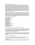
Traffic Mode
If a traffic sensor (TAS) is installed in the aircraft, a specific traffic display can be
accessed for traffic alerts.
1. Message Ack button displays a dedicated traffic page designed to give the pilot
maximum traffic situational awareness. This is a specially configured Map page
with the following settings:
View - center, with heading (or track) up
Range - 10 NM
Base Map - no terrain or political boundaries
Declutter - no symbol or airspace depictions
Datalink Weather - not displayed
Lightning - not displayed
Flight Plan - displayed
Up to 5 non-bearing intruders (traffic threats reported by the traffic sensor without
valid bearing) are listed below the airplane symbol. Acknowledging the TA
message will remove it from the message bar, allowing other messages to be
displayed. The TA message will be automatically removed when the threat is
reduced or the intruder is no longer present.
2. Exit Traffic button restores the Map page to the previous settings. If the Map
page is restored prior to acknowledging a TA, the message will remain displayed
and acknowledging it will once again bring up the dedicated traffic display.
2
1
EX5000 MFD in Traffic Mode
Note: Traffic information is provided to the pilot as an aid to visually acquiring
traffic. Pilots should maneuver their aircraft based only on ATC guidance or
positive acquisition of conflicting traffic.
FlightMax EX5000
-28-
600-00101-000, Rev 02
Database Updates
The MFD is delivered with a current complete database of airports, navaids, airways,
navigational fixes and obstacles. This data is displayed on the moving map to provide
navigational information and situational awareness.
The navigation data for the MFD includes copyrighted data compilations owned
by Jeppesen Sanderson, Inc., for which Avidyne has been granted a limited,
non-exclusive license to use. The copyrighted subject matter may be used only in
connection with the ordinary and intended use of the MFD as described in this manual.
Use for any other purpose, or reproduction or copying of any portion of said
copyrighted subject matter, is strictly prohibited.
The database region map and Update Procedures are on Page 44.
600-00101-000, Rev 02
-29-
FlightMax EX5000
Appendix - Tables
Table 1: Color Code for Sensor Status Block
Symbol
Traffic
Lightning
Status
If the symbol is filled in with blue, the system is
reporting a healthy status and is being displayed
in the mode listed in the sensor status block.
Datalink
Traffic
Lightning
If the symbol is empty (outline only) and blue, that
function is reporting a healthy status, but is turned
off for display on the Map page.
Datalink
Traffic
Lightning
Datalink
Traffic
Lightning
Datalink
FlightMax EX5000
If the symbol is filled with yellow, the system is
unable to display data from that particular sensor.
This may be due to a communication error, the
sensor is not healthy, or there is a configuration
problem.
If the symbol is empty (outline only) and yellow,
that function is not able to display data due to the
same reasons as above, and is turned off from
display on the map page.
-30-
600-00101-000, Rev 02
Appendix - Tables
Symbols
The MFD’s Map uses symbols contained in its navigational database, based on your
navigational mode and flight situation. Map can display the following database items:
• Airports
• Navaids (VORs and NDBs)
• Airways ( Victor and Jet)
• Intersections, waypoints and other named fixes
• Class B, C, and D airspace
• Obstacles (>200’ AGL)
• Certain classes of special use airspace (Prohibited, Restricted, Warning,
Alert and Military Operating Areas)
Navigational symbols used by Map are shown in Table 2 through Table 6.
Table 2: Map Symbols - Navigational Fixes
Symbol
Item
Description
NDB
All NDBs
VOR
All VORs
Intersection
600-00101-000, Rev 02
-31-
Terminal, Jet, and
Victor airway
waypoints
(intersections)
FlightMax EX5000
Appendix - Tables
Note: The various airport types are derived directly from the Jeppesen navigation
database.
Table 3: Map Symbols - Airports
Surface
Hard
Airport Type
Soft
Water
Towered
Towered
Non-Towered
Non-Towered
NOTE: The larger airport symbols are displayed as the map scales are
reduced to the smaller ranges.
Table 4: Map Symbols - Other
Symbol
Item
Symbol
Item
Flight Plan
(inactive leg)*
Single Low
Obstacle
>= 200’ AGL
<1000’ AGL
Flight Plan
(active leg)
Low Obstacles
within 1NM of
eachother
>= 200’ AGL
<1000’ AGL
Map Orientation
Single Obstacle
>=1000’ AGL
Ownship
Symbol
Obstacles
within 1NM of
eachother
>=1000’AGL
Flight Plan,
Course
Waypoints
* -If all legs are shown in white, the GPS is not reporting the active leg
of the flight plan.
FlightMax EX5000
-32-
600-00101-000, Rev 02
Appendix - Tables
Table 5: SUA and TFR Status
Status
Region Type
Inactive
Unknown
Pending
Active
Line
Label
Line
Label
Line
Label
Line
Label
Dashed
Inact
Single
Unk
Single
Pend
Triple
Act
Dashed
Inact
Single
Unk
Single
Pend
Triple
Act
Dashed
N/A
N/A
N/A
Single
N/A
Triple
N/A
Prohibited, Restricted
Warning, Alert, MOA
TFR
N/A
NOTE: For adjacent or overlaying types of Special Use Airspace (e.g. Restricted
Areas or Prohibited Areas within larger MOAs), some masking of the border lines
mayoccur. Pilots must reference current aeronautical charts for accurate boundaries.
Table 6 : AIRMET and SIGMET Boundaries
Line Color
Type
Label
Bright blue
Mountain AIRMET
MTN
Dark yellow
IFR AIRMET
IFR
Orange
Turbulence AIRMET
TURB
Blue
Icing AIRMET
ICE
Dark red
SIGMET AIRMET
SIG
Blue gray
Convective SIGMET
CSIG
600-00101-000, Rev 02
-33-
FlightMax EX5000
Appendix - Tables
Table 6: Data Block Information
Name
TO WPT
NEXT WPT
DEST WPT
Descriptions
Range
Name of, bearing and
distance to the “To”
waypoint in the active
flight plan. Note that the
bearing is from your
present position directly
to the fix. If you are off
course, it will differ from
your planned course.
Also displays ETE
(Estimated Time En route)
5 characters
(Name)
1 to 360 degrees
Name of, bearing and
distance to the “To”
waypoint in the active
flight plan.
Also displays ETE
(Estimated Time En route)
5 characters
(Name)
1 to 360 degrees
0.0 to unlimited NM.
Name of and distance to
final destination waypoint
in system distance units.
Distance is measured
along planned route.
5 characters
0.0 to unlimited NM.
H:MM:SS
0.0 to unlimited NM.
NRST ARPT
Identifier of, bearing and
distance to the nearest
airport.
5 characters
(Name)
LAT/LON
Current lattitude and
longitude in degrees and
decimal minutes.
N/S 0 to 90o 0’
E/W 0 to 180o 0’
BARO ALT
Barometric Altitude
Based on data
from FMS or
GPS (see Note)
NOTE: The Baro Altitude is received from the FMS or GPS (via 429). The FMS/GPS
calculates the altitude based on the barometric pressure entered into the FMS by
the pilot. This display is used to verify what has been put into the FMS/GPS. Do
not rely on this display for terrain separation.
FlightMax EX5000
-34-
600-00101-000, Rev 02
Appendix - Tables
Table 7: Data Block Information (continued)
Name
Descriptions
Range
GND SPD
Current ground speed in
system speed units.
0.0 to 999.9 knots
TRUE AIRSPD
Actual airspeed
From FMS
UTC TIME
UTC (or “Zulu”) time
0 to 23h 59m 59s
LOCAL TIME
Local data and time.
Derived from UTC time
with time zone setting
applied.
0 to 23h 59m 59s
blank
Blank space
Table 8: Engine Instrument Data Block Information
Name
Descriptions
Range
POWER
RPM
Manifold Pressure (MP)
Percent Power (%)
0 - 3,500 RPM
0- 36 Inches of Hg
0 - 200%
FUEL
Fuel Flow &
Gallons Used
0.0 to 30 GPH
0.0 to 99.9 Gallons
FUEL REM
Fuel Amount &
Time Remaining
0.0 to 40.0 Gallons ST
0.0 to 60.0 Gallons LR
0 to 23h 59m
OIL
Oil Temperature &
Oil Pressure
0 - 300º
0 - 100 PSI
LEAN STATE
Status of “Lean” setting:
Best Economy
Best Power
In process of leaning
Leaning interrupted
Power change after lean
Throttle change after lean
Not leaned
Economy
Power
Leaning...
Incomplete
Pwr Change
FF Change
--- (blank)
OAT
Outside Air Temperature
-40ºF to 140º F
-40ºC to 60ºC
Electrical
Bus Voltage (Volts) and
2 to 75 Amperes
Alternator outputs (Amps)
20 to 36 VDC
600-00101-000, Rev 02
-35-
FlightMax EX5000
Appendix - Nav Messages
NAV Messages &
Colors
Meaning
Recommended
Pilot Action
Nav Source Data is valid
GPS/FMS indicates that the
computed position data is valid.
Acknowledge
Nav Source Data is Not
valid (err=x)
Your GPS/FMS has not computed a valid position or is not supplying valid data. Flight Plan will
not be presented on the Radar
display.
Check GPS for valid position.
Have maintenance check
GPS/FMS and installation
Nav Source :Can't Open
Port
The GPS/FMS interface cannot Have maintenance check
open the assigned port.
configuration and installaGenerally indicates a configura- tion
tion error.
Nav Source
Reconnecting…
EX5000 is attempting to reconnect to the port that is connected to the GPS/FMS.
Acknowledge
Nav Source is Not
Communicating
EX5000 does not detect any
data being sent from the
GPS/FMS.
Have maintenance check
configuration and installation
Nav Source Data Format
Error
Invalid data is coming from your Have maintenance check
GPS/FMS. If persistent, general- configuration and installaly indicates a configuration error. tion
Heading Data is NOT
Valid
GPS/FMS is configured as the
Map heading source and that
data ceases to be available or
becomes invalid.
Have maintenance check
configuration and installation
Heading Data is Valid
GPS navigator is configured as
the Map heading source and
that data becomes valid following an acknowledgement of an
invalid message.
Acknowledge
FlightMax EX5000
-36-
600-00101-000, Rev 02
Appendix - Traffic Messages
Traffic Messages
& Colors
Meaning
Recommended
Pilot Action
Traffic Sensor is
Operating Normally
Traffic sensor is operating in a
Acknowledge
normal state from a recoverable
fault that was previously
acknowledged.
Traffic <Bearing> /
<Distance > / <Relative
Altitude>
Traffic Advisory
Acknowledge to go to dedicatd traffic page and begin
looking for traffic.
Traffic <Distance> /
<Relative Altitude>
Traffic Advisories with no bearing information.
Acknowledge to go to dedicatd traffic page and begin
looking for traffic.
Traffic <Bearing> /
<Distance>
Traffic Advisories with no relative altitude information.
Acknowledge to go to dedicatd traffic page and begin
looking for traffic.
Traffic <Distance>
Traffic Advisories with no bear- Acknowledge to go to dediing and no relative altitude infor- catd traffic page and begin
mation.
looking for traffic.
Traffic Sensor is in
Stand- By
MFD receives a "Stand- By"
Pressing “Traffic” button to
transmission from the traffic sen- select a traffic mode.
sor.
Have maintenance check
configuration and installation if message persists.
Traffic Sensor is in
Self- Test
Traffic sensor is in self test
mode.
Traffic Sensor is Not
Communicating
Traffic sensor is not transmitting Have maintenance check
data.
configuration and installation
TCAD Altitude
TCAD sensor is not receiving
altitude information.
Have maintenance check
configuration and installation
Traffic Heading Source
Failed
TAS is configured as the Map
Heading source and a "fatal
heading fault" is received.
Have maintenance check
configuration and installation
Traffic Heading Source is
Valid
Traffic sensor is configured as
the Map Heading source and is
valid.
Acknowledge
Unavailable
600-00101-000, Rev 02
-37-
Acknowledge
FlightMax EX5000
Appendix - Lightning Messages
Lightning Messages
& Colors
Meaning
Recommended
Pilot Action
Lightning Sensor is
Operating Normally
Lightning source is operating in
a normal state from a recoverable fault that was previously
acknowledged.
Acknowledge
Lightning Sensor is in
Noise- Monitor Mode
Lightning source is in NoiseMonitor Mode.
Have maintenance check
configuration and installation.
Lightning Sensor is in
Demo Mode
Lightning source is in Demo
Mode.
Have maintenance check
configuration and installation.
Lightning Sensor is in
Test Mode
lightning sensor in a self- test
mode.
Acknowledge
Lightning Sensor
ERROR
MFD receives a "recoverable
fault" notification.
Have maintenance check
configuration and installation.
Lightning Sensor has
FAILED
MFD receives a "fatal fault"
notification.
Have maintenance check
configuration and installation.
Lightning Sensor is Not
Communicating
MFD receiving no data from the Have maintenance check
lightning sensor.
configuration and installation.
Lightning Ahead
Stormscope is indicating disDetermine location of lightcharge activity horizontally with- ning and avoid.
in ± 22 ° of the aircraft nose and
within 75nm.
Lightning Heading
Source Failed
Stormscope is configured as a
heading source and a "fatal
heading fault" is received.
Have maintenance check
configuration and installation.
Lightning Heading
Source OK
Stormscope is configured with
heading input.
Acknowledge
Lightning Antenna
Location Changed
Stormscope antenna location
disagrees with MFD setting.
Have maintenance check
configuration and installation.
FlightMax EX5000
-38-
600-00101-000, Rev 02
Appendix - Datalink Messages
Datalink Messages
& Colors
Meaning
Recommended
Pilot Action
Datalink Sensor is
Operating Normally
Satellite communicator is operat- Acknowledge
ing normally after a recoverable
fault was previously acknowledged.
Datalink Sensor is NOT
Communicating
Satellite communicator has
stopped communicating.
Restart system. If problem
persists, contact Avidyne.
Datalink Sensor
Configuration Error
COMM port is configured incorrectly.
Restart system. If problem
persists, contact Avidyne.
Datalink Sensor Data is
Invalid
MFD receives a "recoverable
fault" notification.
Have maintenance check
configuration and installation.
Datalink METAR symbols
> 90 minutes
METARs are older than 90 minutes from their time of reception.
Go to Datalink Setup page
and request refresh.
Datalink AIRMETs/
SIGMETs > 90 minutes
AIRMETs/ SIGMETs are older
than 90 minutes.
Go to Datalink Setup page
and request refresh.
Datalink SUA Status > 90
minutes
SUA Status data are older than
90 minutes.
Go to Datalink Setup page
and request refresh.
Datalink TFRs > 90
minutes
TFR data are older than 90 minutes.
Go to Datalink Setup page
and request refresh.
Datalink Data not yet
received
Datalink is Enabled and no
Datalink data has been received
within 10 minutes of MFD
initialization compete.
Acknowledge
Datalink Airmets/ Sigmets
not yet received
AIRMETs/ SIGMETs are selected
and they are not received within
15 minutes of the initial datalink
update.
SUA Status/ TFRs are selected
and SUA Status is not received
within 15 minutes of the initial
datalink update.
UA Status/ TFRs are selected
and TFRs are not received within
15 minutes of the initial datalink
update.
METARs are selected and they
are not received within 15 minutes of the initial datalink update.
Acknowledge
Datalink: Idle
No data being sent or recieved.
None necessary.
NXR Invalid
NEXRAD temporarily not able to
be displayed.
Wait for next
NEXRAD update. Check
system in Setup pages.
SUA Status not yet
received
TFRs not yet received
METARs Symbols not yet
received
600-00101-000, Rev 02
-39-
Acknowledge
Acknowledge
Acknowledge
FlightMax EX5000
Appendix - Engine Messages
Engine Messages
& Colors
Meaning
Recommended
Pilot Action
Engine Sensor Unit is
Operating Normally
Engine siu is operating in a normal state
Acknowledge
from a recoverable fault that was previously acknowledged.
Engine Sensor Unit is
Not Communicating
MFD receiving no data from Engine siu.
Engine Sensor Unit
Configuration Error
MFD receiving invalid data from the Engine Have maintenance
siu.
check configuration
and installation.
Have maintenance
check configuration
and installation.
PFD Messages
PFD Messages
& Colors
Meaning
Recommended
Pilot Action
PFD is Operating
Normally
PFD is operating in a normal state from a Acknowledge
recoverable fault that was previously
acknowledged.
PFD is Not
Communicating
MFD receiving no data from PFD.
Have maintenance
check configuration
and installation.
Engine Caution Messages
Engine Cautions
& Colors
Meaning
Recommended Pilot
Action
Check Oil Temp
MFD has detected an
oil temperature outside the
normal operating range.
Check Oil Press
MFD has detected an
Acknowledge, Examine Oil
oil pressure outside the normal Pressure on Engine Page.
operating range.
Take corrective action and land
immediately, if necessary.
Check Volts
MFD has detected bus voltage Acknowledge, Examine Voltage
outside the normal operating
Indicator on Engine Page. Take
range.
corrective action and land as
soon as practical.
Check CHT
MFD has detected a cylinder
head temperature higher than
the normal operating range.
FlightMax EX5000
-40-
Acknowledge, Examine Oil
Temperature on Engne Page.
Take corrective action and land
immediately, if necessary.
Acknowledge, Examine CHT
indicators on Engine Page.
Take corrective action as
required.
600-00101-000, Rev 02
Appendix - Navigation Database Update Procedure
The MFD utilizes a Jeppesen NavDataTM database of airports, navaids, airways,
and navigational fixes. Navigation data is updated on 28-day cycles, and it is
recommended that the database should be kept current.
To perform a data update:
1. Turn power OFF to the MFD.
2. Install data disk into the dataloader.
Connect one end of the interconnect cable to the dataloader and the other end to the
MFD data port on the front panel.
Note: Ensure that the dataloader is supported and not dangling by the cable.
This may cause an intermittent connection, which will result in an unsuccessful
data update.
3. Apply power to the MFD by turning ON the avionics master switch.
The Data Loader screen is displayed.
Note: If the "Press Any Bezel Key" message is displayed, the dataloader drive
was not detected by the MFD. Check the connection between the dataloader
drive and the MFD. Restart procedure at step 1.
4. Press the "Proceed" button. Do not turn off the MFD or disconnect the interconnect cable during a data load.
The data load is complete when the "Press Any Bezel Key" message is displayed.
Remove the dataloader drive and interconnect cable and store in a safe place.
Region I
Region II
Databases are available for two regions of the world.
Region I - Americas
Region II - International (does not include Americas)
600-00101-000, Rev 02
-41-
FlightMax EX5000
Appendix - Failure Indications
Loss of Position
If the position source becomes unavailable or invalid, the following conditions will occur:
• all traffic, and lightning data is removed from the display.
• the aircraft symbol is removed from the display.
• the compass labels (N,S, E, and W) are removed from the display.
• the map will remain static, centered on last known good position.
• the map orientation annunciation is removed from the display.
• the map is oriented True North Up.
Recommended course of action:
• For aircraft equipped with dual GPS, select the Setup Page and press
the “Swap to GPS X” button.
• For aircraft equipped with a single GPS, follow the GPS supplier
troubleshooting guide.
When position data is restored, Map will resume normal operations.
Loss of Heading/Track
If the heading/track source becomes unavailable or invalid, the following conditions will
occur:
• all traffic, and lightning data is removed from the display.
• the aircraft symbol is replaced by a direction-less symbol (a white + symbol).
• the compass labels (N,S, E, and W) are removed from the display.
• the map and flight plan data will continue to be displayed.
• the map orientation annunciation is removed from the display
• the heading/track indicator will display a series of dashes ("---")
• the map is oriented True North Up.
Recommended course of action:
• Call your Avidyne Customer Service representative.
When heading/track is restored, Map will resume normal operations.
FlightMax EX5000
-42-
600-00101-000, Rev 02
Appendix - Failure Indications
Unhealthy Sensor
Map monitors the "health" of the sensors (traffic and lightning) by means of a signal
pulse. Map looks for a signal every three seconds from each sensor. If it doesn’t see
this signal it assumes the sensor has failed in some way. When this happens, the
following occurs on the display:
• sensor data is removed from the overlay display.
• the word "FAIL" is displayed in the sensor's status line in yellow.
• the sensor symbol changes from cyan to yellow (if the sensor was on).
Recommended course of action:
• Select the Setup Page and perform Self-Test for the applicable sensor.
CMOS Battery Failure
In the event of an internal battery failure, the following message will occur after
system start-up:
WARNING: Check system time. Check database expiration date. Press any
bezel key to continue.
This message indicates that the internal battery that maintains system date and time
settings has failed, in which case the following system defaults are used:
Date - Jan 01, 2000
Time- 00:00:00 (local)
These defaults will be overridden when GPS date and time are sent to the MFD via
ARINC 429 from the GPS navigator.
This message alerts the pilot to check the navigation database expiration date and verify
that the database has not expired, since the system will not automatically recognize it.
The system should be returned to Avidyne for CMOS battery replacement.
600-00101-000, Rev 02
-43-
FlightMax EX5000
Appendix - Failure Indications
Engine SIU Failure
In the event of an engine sensor unit, or SIU, failure, any affected indicators will show
a failure indication by:
Dial Gauges: Needle Pointer removed
Numeric Readouts: Displayed as three white dashes
Bar Graphs: Disappear
Recommended Action: For failure of single indicators, land as soon as practical and
consult a maintenance facility. If all indicators have failed, check and/or cycle the
circuit breaker for the engine sensor interface unit (SIU). If the function is not restored,
land as soon as practical and have a maintenance facility inspect the system.
FlightMax EX5000
-44-
600-00101-000, Rev 02
600-00101-000
Rev 02
AV I D Y N E C O R P O R AT I O N
55 Old Bedford Road
Lincoln, MA 01773
Te l e p h o n e : 7 8 1 - 4 0 2 - 7 4 0 0
T o l l F r e e : 8 0 0 - A V I D Y N E (800-284-3963)
FAX:781-402-7599
www.avidyne.com
P/N 600-00101-000
Rev 02
11 / 0 3
© 2003 Avidyne Corporation
All Rights Reserved.
Avidyne® and FlightMax™ are trademarks of Avidyne Corp.
SKYWATCH® and STORMSCOPE® are trademarks of Goodrich Corp.