1
DOT MATRIX PRINTER
CBM-910
Type II
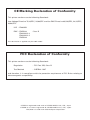
CE Marking Declaration of Conformity
This printer conforms to the following Standards:
Low Voltage Directive 73/23/EEC, 93/68/EEC and the EMC Directive 89/336/EEC, 92/31/EEC,
93/68/EEC.
LVD : EN60950
EMC : EN55022
EN61000-3-2
EN61000-3-3
EN55024
Class B
This declaration is applied only for 230V model.
FCC Declaration of Conformity
This printer conforms to the following Standards:
Regulation
: FCC Part 15B, Class B
Test Method
: CISPR22: 1997
and therefore is in compliance with the protection requirement of FCC Rules relating to
electromagnetic compatibility.
CITIZEN is registered trade mark of CITIZEN WATCH CO., LTD., Japan
CITIZEN es una marca registrada de CITIZEN WATCH CO., LTD., Japón
ESC/POS is a trade mark of Seiko Epson Corporation.
—1—
Compliance Statements
FCC Compliance Statement for American Users
This equipment has been tested and found to comply with the limits for a Class B digital device,
pursuant to Part 15 of the FCC Rules. These limits are designed to provide reasonable protection
against harmful interference in a residential installation. This equipment generates, uses, and
can radiate radio frequency energy and, if not installed and used in accordance with the
instructions, may cause harmful interference to radio communications. However, there is no
guarantee that interference will not occur in a particular installation. If this equipment does
cause interference to radio or television reception, which can be determined by turning the
equipment off and on, the user is encouraged to try to correct the interference by one or more of
the following measures:
• Reorient or relocate the receiving antenna.
• Increase the separation between the equipment and receiver.
• Connect the equipment into an outlet on a circuit different from that to which receiver is
connected.
• Consult the dealer or an experienced radio/TV technician for help.
CAUTION: Use shielded cables to connect this device to computers.
Any changes or modifications not expressly approved by the grantee of this device could void
the user’s authority to operate the equipment.
EMI Compliance Statement for Canadian Users
• This Class B digital apparatus complies with Canadian ICES-003.
• Cet appareil numérique de la classe B est conforme à la norme NMB-003 du Canada.
—2—
< GENERAL PRECAUTIONS >
1. Prior to using the printer, be sure to read this User’s Manual thoroughly. Please keep it
handy so that you can refer to it whenever necessary.
2. The information contained herein is subject to change without prior notice.
3. All rights reserved. Reproduction of part or all of this document is prohibited without written
permission from CITIZEN SYSTEMS.
4. Except explained elsewhere in this manual, do not attempt to service, disassemble or repair
this product by yourself.
5. Note that CITIZEN SYSTEMS shall not be responsible for any damage attributable to incorrect
operation/handling or improper operating environments which are not specified in this
manual.
6. Operate this printer only as described in this manual. Failure to do so may cause accidents
or other problems.
7. Data are basically for temporary use, not stored for a long period or permanently. Please
note that CITIZEN SYSTEMS is not responsible for any damage or lost profit resulting from
the loss of data caused by accidents, repairs, tests, or any other occurrence.
8. If you have any question or comment regarding the information contained in this manual,
please contact your CITIZEN SYSTEMS dealer.
9. Please note CITIZEN SYSTEMS is not responsible for anything that may occur from operating
this printer regardless of what is stated in “8” above.
10. If you find any missing pages or pages out of order in this manual, please contact your
CITIZEN SYSTEMS dealer for a replacement.
—1—
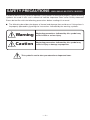
SAFETY PRECAUTIONS -WHICH SHOULD BE STRICTLY OBSERVED
In order to prevent injury hazard to operators, third parties or damage to property, special warning
symbols are used in this user’s manual to indicate important items to be strictly observed.
Please be familiar with the following precautions before reading this manual.
● The following describes the degree of hazard and damage that could occur if the printer is
improperly operated by ignoring the instructions indicated by the warning symbols.
Warning
Neglecting precautions indicated by this symbol may
result in fatal or serious injury.
Caution
Neglecting precautions indicated by this symbol may
result in injury or damage to properties.
This symbol is used to alert your attention to important items.
—2—
WARNING
● Never handle the printer in the manners described below; otherwise, it may be
damaged, get out of order or overheated, possibly causing smoke, fire or electric
shock.
If the printer is damaged or breaks down, be sure to turn off the power, disconnect
the power plug from the wall outlet, and contact your CITIZEN SYSTEMS dealer.
• Do not allow the printer to be subjected to any strong impact or shock, such as
stamping, hitting, dropping, and the like.
• Install the printer in a well-ventilated place. Do not use the printer in such a manner
that its ventilation slots are blocked.
• Do not install the printer in a place like a laboratory where chemical reactions are
expected, or in a place where saltish gases are present in the atmosphere.
• Use the printer only on the specified voltage and frequency.
• Do not connect/disconnect the power cord or data cable by holding the cable. Do
not pull or carry the printer in such a manner that undesirable force is applied to
the cables.
• Do not drop or insert any foreign substances, such as paper clips or pins, into the
printer.
• Do not connect the printer to an electrical outlet shared by other devices.
• Do not spill any liquid on or spray any chemical-containing liquid over the printer.
If any liquid is spilled on the printer, turn it off, disconnect the power cord from the
wall outlet, and contact your CITIZEN SYSTEMS dealer.
• Do not disassemble or modify the printer in any manner; otherwise, a fire or electric
shock may result.
● The plastic bag the printer came in must be disposed of properly or kept away from
children. Wearing it over the head may lead to suffocation.
—3—
PRECAUTIONS FOR INSTALLATION
● Do not use or store the printer in a place exposed to heat of fire, moisture or direct
sunlight, or in a place where the prescribed operating temperature and humidity are
not met, or in a place exposed to oily mist, iron powder or dust; otherwise, the printer
may get out of order, emit smoke or catch fire.
● Do not install the printer in a place like a laboratory where chemical reactions are
expected, or in a place where saltish gases are present in the atmosphere; otherwise,
there may occur a danger of fire or electric shock.
● Install the printer on a sturdy and good ventilation place and free from any vibration.
(Be careful not to block the ventilation slots of the printer.)
● Do not put any object on the printer, or this may cause a trouble.
● Do not use the printer near a radio or television receiver. Avoid sharing an electrical
outlet with a radio or television receiver, or this may cause a reception problem.
● Use the printer only on the specified voltage and frequency; otherwise it may emit
smoke, catch fire or cause other problems.
● Confirm that the wall outlet used for printer connection has sufficient electrical
capacity.
● Avoid sharing a single electrical outlet with other devices; otherwise, the electrical
capacity may be exceeded, causing the outlet to overheat or the power supply to be
shut down. Also, do not stamp or put any object on the cables.
● Never connect the grounding cable to a gas pipe, or this may lead to a danger of
explosion. Before connecting or disconnecting the grounding cable, be sure to
disconnect the power plug from the wall outlet.
● Be sure to turn off the power of the printer and the host computer connected before
connecting or disconnecting the cables; always hold both plug and cable. Do not
pull or carry the printer in such a manner that an undesirable load is applied to the
cables.
● Connect the connector cables correctly and securely. Especially, if a connection is
made with the polarity reversed, internal elements inside the printer may be damaged
or the host computer connected may be adversely affected.
● Use shielding wires or twist paired wires for signal lines in order to minimize the
effects from noise. Avoid connecting to a device that is likely to generate much
noise.
● Install and use the printer in a place provided with a suitable wall outlet nearby so
that you can immediately disconnect the power plug to shut off the power to the
printer if an abnormal condition occurs.
● When transporting the equipment, remove the paper roll from it.
—4—
PRECAUTIONS FOR HANDLING
Do not handle the equipment in the following manners, because problems may result.
● Do not print when there is no recording paper or ink ribbon set in the equipment.
● Be careful not to drop foreign substances, such as clips, pins, and screws, into the
equipment.
● Do not spill any liquid or spray any chemical-containing liquid over the equipment.
● Do not stamp on, drop, hit, or give a strong shock to the equipment.
● Never use a pointed object, such as a pen, to operate the operation panel.
● Do not use Scotch tape to fasten paper together for continuous use.
● Never pull the set paper forcibly.
● Replace the ink ribbon before it is broken by overuse. Do not refill the ink ribbon.
● Leaving the printer unused for a long time with a ribbon cassette loaded may cause
smudged printing. Continuous printing at low temperature may cause thin printing
due to the characteristic of ink.
● Do not deliver the equipment with a ribbon cassette loaded.
To Prevent Injury and Spreading of Damage
● Do not touch the printing part of the print head.
● While the equipment power is on, do not touch the moving parts, such as a cutter
and gear, or electric parts inside the equipment.
● Be careful to avoid bodily injure or damaging other objects with an edge of sheet
metal.
● Should any error occur while operating the equipment, stop using it immediately,
disconnect the power plug from the plug socket, and then contact your CITIZEN
SYSTEMS dealer.
—5—
THE TABLE OF CONTENTS
1. INTRODUCTION .................................................................................. 8
1.1 Features .................................................................................................... 8
1.2 Accessories ............................................................................................... 8
2. TYPE CLASSIFICATIONS .................................................................... 9
2.1 Type ........................................................................................................... 9
2.2 AC Adapter ............................................................................................... 9
2.3 Specifications ......................................................................................... 10
3. EXTERNAL APPEARANCE AND PART DESCRIPTIONS................... 11
3.1 External Appearance .............................................................................. 11
3.2 Part Descriptions .................................................................................... 12
4. OPERATIONS ..................................................................................... 13
4.1
4.2
4.3
4.4
4.5
4.6
4.7
4.8
Connection of the AC Adapter .............................................................. 13
Setting of the Printer Cover ................................................................... 14
Setting Ribbon Cassettes ...................................................................... 15
Setting Paper .......................................................................................... 16
Self-Printing Function ............................................................................ 18
Memory Switch Setting ......................................................................... 19
Paper-Near-End, Mechanical Alarm, Memory Error ............................ 21
General Remarks .................................................................................... 22
5. PARALLEL INTERFACE ...................................................................... 23
5.1
5.2
5.3
5.4
Specifications ......................................................................................... 23
Connector Pin Assignment .................................................................... 23
Description of Input/Output Signals ..................................................... 24
Electrical Characteristics ........................................................................ 25
6. SERIAL INTERFACE ........................................................................... 26
6.1
6.2
6.3
6.4
6.5
Specifications ......................................................................................... 26
Connector Pin Assignment .................................................................... 27
Description of Input/Output Signal ....................................................... 28
Electrical Characteristics ........................................................................ 29
Error Detection ....................................................................................... 30
7. DIP SWITCH SETTING ....................................................................... 31
7.1 Serial Interface Type .............................................................................. 31
7.2 Parallel Interface Type ............................................................................ 32
8. PRINT CONTROL FUNCTION ........................................................... 33
8.1 List of Control Codes ............................................................................. 33
8.2 Control Code Details .............................................................................. 34
—6—
9. CHARACTER CODE TABLE ............................................................... 47
9.1 ASCII + 910 Emulation (International) .................................................. 47
9.2 910 Emulation (Japan) ........................................................................... 47
9.3 Codepage PC437 (USA, Standard Europe) .......................................... 48
9.4 Katakana ................................................................................................. 48
9.5 Codepage PC858 (Multilingual) ............................................................ 49
9.6 Codepage PC860 (Portuguese) ............................................................. 49
9.7 Codepage PC863 (Canadian-French) .................................................... 50
9.8 Codepage PC865 (Nordic) ..................................................................... 50
9.9 Codepage PC852 (Eastern Europe) ....................................................... 51
9.10 Codepage PC866 (Russian) ................................................................. 51
9.11 Codepage PC857 (Turkish) ................................................................... 52
9.12 Codepage WPC1252 (Windows Latin1) .............................................. 52
9.13 Codepage PC864 (Arabic) .................................................................... 53
9.14 Codepage PC869 (Greek) ..................................................................... 53
9.15 International Character Code Table .................................................... 54
10. EXTERNAL DIMENSIONS ............................................................... 55
—7—
1. INTRODUCTION
The CBM-910II is a dot-impact printer widely usable with various data communication
terminals and measurement terminals.
This printer, being extremely compact and equipped with extensive functions, is
suitable to a wide range of applications.
Read this manual thoroughly to understand the product before use.
1.1 Features
● Compact desk-top dot matrix printer
● Light weight
● High speed printing
● Paper-near-end detecting function
● Conformity to RS-232C and Centronics.
● Low power consumption
● Low price
● Wall mountable
1.2 Accessories
Confirm that the printer is supplied together with the following accessories.
Paper roll (1 roll)
Ribbon cassette (1 unit)
AC adapter (1 unit)
User’s manual (1 booklet)
—8—
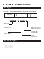
2. TYPE CLASSIFICATIONS
2.1 Type
The product is categorized according to the naming plan indicated below.
CBM-910II
24
40
P
R
J
F
100
120
230
A
B
CBM-910II - 24 R J 100 - A
Model Name
Printer cover
A: 60 mm (Dia.) Paper roll
B: 80 mm (Dia.) Paper roll
Number of columns
24: 24 columns/144 dots
40: 40 columns/180 dots
Adapter
100: For AC 100 V
120: For AC 120 V
230: For AC 230 V
Interface
P: Parallel (Conformity to Centronics)
R: Serial (RS-232C)
Character set
J: Japan
F: International
2.2 AC Adapter
Please use the exclusive adapter indicated below.
For 92AD-J (AC 100 V)
For 92AD-U (AC 120 V)
For 92AD-E (AC 230 V)
—9—
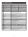
2.3 Specifications
Item
1
Printing method
CBM-910II-24
Dot matrix
CBM-910II-40
2
Printing direction
3
Character configuration (W × H) (5 + 1) × 8
One-way printing
(4 + 0.5) × 8
4
Number of columns per line
40 columns: 180 dots/line
5
Printing speed
Approx. 2.5 lines/sec.
Approx. 1.8 lines/sec.
6
Character size (W × H)
1.62 × 2.4 mm
1.08 × 2.4 mm
7
Character spacing
1.98 mm
1.19 mm
8
Line pitch
3.52 mm
24 columns: 144 dots/line
9
Paper feed speed
Approx. 5 lines/s
10
Paper
Single sheet, copier paper (original and copy),
Total thickness: 0.13 mm or less
Paper roll: 57.5 ±0.5 (W) × 60 or 80 (Dia) mm
Core ID: φ12 ±1 mm Core OD: φ18 ±1 mm
Approx. 3.6 lines/s
11
Interface
Parallel Interface (Conformity to Centronics) or
Serial Interface (RS-232C)
12
Input buffer
2k bytes/72 bytes
(Selectable by memory switch on Serial I/F model)
13
Emulation
CBM-910 emulation and IDP3110 emulation
(selectable with memory switch)
14
Code page
PC437, 852, 857, 858, 860, 863, 864, 865, 866, 869, WPC1252,
Katakana, CBM-910 emulation (Japan, International)
15
Paper-near-end detection
Printing suspended when printing paper gets scarce.
16
Ink ribbon
Purple (Private ribbon cassette)
Service life: approx. 250,000 letters
17
Voltage
DC 7 V ±1 V (Printing)
Use exclusive adapter (DC 7 V 1.6 A)
18
Power consumption
Printing: Approx. 7 VA
Stand-by: Approx. 0.5 VA
19
Weight
Approx. 470 g
20
Reliability
MCBF: 1.5 million lines
21
Dimension
106 (W) × 180 (D) × 88( H) mm
22
Operating temperature and
humidity
0 to 40°C, 35 to 85% RH (without condensation)
23
Storage temperature and
humidity
–20 to 60°C, 10 to 90% RH (without condensation)
24
Specifications
CE Marking/TUV- GS/FCC class B/VCCI class B
(AC adapter PSE/UL/C- UL/TUV- GS)
— 10 —
MCBF: 1 million lines
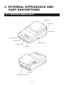
3. EXTERNAL APPEARANCE AND
PART DESCRIPTIONS
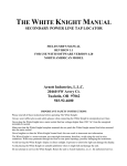
3.1 External Appearance
(8) Print cover
Upper cover
Lower cover
(3) Power lamp
(4) SEL lamp
(2) Power switch
(6) SEL switch
(5) LF switch
(1) DC jack
(7) Interface connector
— 11 —
3.2 Part Descriptions
(1) DC jack
Insert the output plug of the AC adapter attached.
(2) Power switch
When switched ON, power is supplied to the printer and
the Power lamp goes on.
(3) Power lamp
Lighted when power is turned ON and goes out when turned
OFF.
Blinks during memory switch setting and at the occurrence
of memory error. While memory switch setting error is
present, the Power lamp blinks at 1/10-second intervals.
While memory error is present, the Power lamp and the
SEL lamp blink simultaneously at 1/10-second intervals. The
memory switch setting error can be recovered by resetting
but memory error is not recoverable.
(4) SEL lamp
Printer lights up in Select (ON LINE) state, and is put off in
Deselect (OFF LINE) state. Printing operation is available
only while this lamp is lit.
1) It blinks, for paper-near-end, at 0.5-second intervals.
Supply paper and press the SEL switch to turn off the
lamp.
2) On occurrence of any alarm state (blinking) due to any
reason other than paper-near-end, it starts blinking at
1/4-second intervals. Eliminate the cause and either
press SEL switch or turn the power off and on again to
stop blinking.
(5) LF switch
Paper is fed when switch is pressed (deselect condition
only). Used to supply paper or to insert some space in the
output.
(6) SEL switch
Printer is selected (ON LINE) by pressing this switch.
Printer is deselected (OFF LINE) by pressing the switch
again.
Also used to release alarm state. In Deselect state, if data
still remain in the input buffer, they are all printed out.
(7) Interface connector
Printer is connected to various hosts via cables. Please
ensure that both the printer and the host are turned off
before connecting.
(8) Printer cover
Opened to exchange ribbon cassette and paper roll.
— 12 —
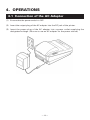
4. OPERATIONS
4.1 Connection of the AC Adapter
(1) Ensure that the power switch is OFF.
(2) Insert the output plug of the AC adapter into the DC jack of the printer.
(3) Insert the power plug of the AC adapter into a power outlet supplying the
designated voltage. (Be sure to use an AC adapter for the power source.)
— 13 —
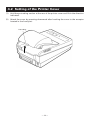
4.2 Setting of the Printer Cover
(1) Hold the protruding section at the rear of the printer cover and lift in the direction
indicated.
(2) Attach the cover by pressing downward after hooking the cover to the acceptor
located in the front part.
Protruding
— 14 —
4.3 Setting Ribbon Cassettes
(1) Remove the printer cover turning OFF the printer.
(2) Press down on the Ribbon cassette while inserting the ribbon between the printing
head and the platen.
(3) Wind up the ribbon slack by turning the knob in the direction of the arrow.
Knob
Platen
Printing head
— 15 —
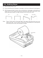
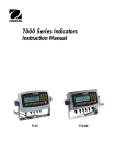
4.4 Setting Paper
(1) Remove the printer cover.
(2) Ensure that the end of the paper is straight or incline as indicated in the diagram.
(3) With the paper holder thrown in the arrow direction, load paper so that the top of
paper go 5 to 6 cm beyond the printer mechanism and attach the printer cover
while passing the paper through the eject slot of the printer cover.
OK
Note:
OK
NO GOOD
NO GOOD
Paper, if held aslant at the paper feed or the paper discharge side, may cause
paper jamming. On occurrence of the above, immediately turn off the power
and slowly pull out the jammed paper upright.
Paper holder
— 16 —
*
SPECIAL REMARKS CONCERNING PAPER
SHAPE: The beginning of winding (end part of the inside diameter) should satisfy the following (Refer
to Drawing A):
1. Free of fold and well aligned to inside diameter
2. Free of flaps
3. Not adhered to core part (if there is one)
The beginning of winding
Drawing A
Not accepted
RECOMMENDED PAPER:
Single paper ... 45 ~ 55 kg/1,000 sheets/1,091 × 788 mm
Copy paper ... Non-carbon paper/original (34 kg-paper) + copy 1 sheet (34 kg-paper)
Total thickness ... 0.13 mm or less
— 17 —
4.5 Self-Printing Function
When activating self-printing function, be sure to start with a paper loaded (or in the
printable state).
(1) Test printing
Turn the printer power on while pressing and holding the LF switch, and the
printer starts printing the status of current setting of DIP switch (including the
content of setting in case of serial printer) and all characters available with the
printer.
The SEL lamp is held off and BUSY signal is output during test printing.
On completion of test printing, the printer enters the standby state awaiting print
data.
(2) Hexadecimal dump mode
Turn the printer power on with the LF switch and SEL switch pressed and held.
The printer prints Hexadecimal Dump characters and then prints all data sent
from the host in hexadecimal code.
When data for the last line is not sufficient for full one line, data of the last line is
printed out with SEL switch pressed and deselected (OFF LINE).
This mode lasts till power is turned off.
Example of Printing in Dump Mode
31
39
41
49
51
32
3A
42
4A
52
33
3B
43
4B
53
34
3C
44
4C
54
35
3D
45
4D
55
36
3E
46
4E
56
37
3F
47
4F
57
— 18 —
38
40
48
50
58
12345678
9*+,-./@
ABCDEFGH
IJKLMNOP
QRSTUVWX
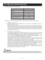
4.6 Memory Switch Setting
<Memory Switch Initial Setting>
International character selection
Japan (910JPN)
Japanese
Code page
910-compatible (Japan)
Emulation
CBM910
Ack timing
After
Paper-near-end selection
Valid
SEL/DESEL at power ON
SEL
Busy signal clear timing
Standard
Buffer Size (Serial I/F)
2k bytes
Memory switch can be changed by a command or by manual operation.
a)
Change by command
Memory switch can be changed by a command. For details, refer to 8.
Print Control Function.
When the printer receives the command, it outputs a BUSY signal and enters
memory setting mode. After writing into memory switch, software resetting
is carried out and the receive buffer/print buffer are cleared causing each
set value to return to the initial value and then the contents of the memory
switch(es) are reloaded.
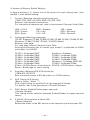
b)
Change by manual operation
Turn the printer power on with DIP switch No. 4 set to ON and by pressing
and holding the SEL switch. The printer prints the information on the current
memory switch setting and then enters the Change Setting mode.
In this case, the POWER lamp blinks at 1-second intervals while the SEL
lamp is kept turned off and BUSY signal outputted.
Using the SEL switch and LF switch, choose one of the options for each
setting item. Then memory switch can be set or changed. Setting items
and options are printed each time the switch is pressed.
The SEL switch allows the option being printed to be determined as the set
value for current setting item, advancing to the next option item. The LF
switch allows the option currently being printed to be deselected among
the same setting items and the next option item to be printed.
To fix the value set by the memory switch when the option item of the last
setting items is selected, press the SEL switch. To restart setting from the
first setting items, press the LF switch.
NOTE
Before turning the printer power on, restore the DIP switch No. 4 to the former position.
— 19 —
<Contents of Memory Switch Setting>
In square brackets ([ ]), choose one of the options for each setting item. Item
marked * is the default setting.
1.
Country (Selecting international character set)
[*USA, FRA, GER, U.K, DEN, SWE, ITA, SPE, JPN]
Selects a international character set.
For international character set, refer to International Character Code Table.
USA = U.S.A
FRA = France
SPA = Spain
2.
SWE = Sweden
ITA = Italy
U.K = U.K.
JPN = Japan
GER = Germany
DEN = Denmark
Code page (Selecting code page)
[CP-437, Katakana, CP-858, CP-860, CP-863, CP-865, CP-852, CP-866, CP-857,
Windows, CP-864, CP-869, *910Intl, *910JPN, Space]
Selects a code page.
For code page, refer to Character Code Table.
Among the character sets for model type, model F is defaulted to 910Intl
and model J to 910JPN.
CP-437 = Codepage PC437
CP-858 = Codepage PC858
CP-863 = Codepage PC863
CP-852 = Codepage PC852
CP-857 = Codepage PC857
CP-864 = Codepage PC864
910Intl = 910 Emulation (International)
Space = Blank page for user’s setting
Katakana = Katakana
CP-860 = Codepage PC860
CP-865 = Codepage PC865
CP-866 = Codepage PC866
Windows = Codepage WPC1252
CP-869 = Codepage PC869
910JPN = 910 Emulation (Japan)
3.
Emulation (Selecting 910/3110 Emulation)
[*CBM-910, iDP-3110]
Sets command system to 910 Emulation or 3110 Emulation.
4.
ACK Timing (ACK timing)
[Before, Center, *After] *1
ACK output timing for parallel I/F can be changed in 3 steps.
For details, refer to the description of Parallel Interface.
5.
P.N.E. Sensor (Enable/Disable paper-near-end)
[*Enable, Disable]
This setting allows selection between Enable/Disable of paper-near-end
sensor.
6.
P-ON Sel (Online status at Power ON)
[*Select, Deselect]
Selects the status of the SEL switch on the operation panel at power ON.
— 20 —
7.
BUSY (Busy signal clear timing)
[*Standard, CBM-910] *1
Selects the clear timing of Busy signal for parallel I/F.
Standard: Clears after confirming the rise of STB signal.
CBM-910: Clears after completing data storage to input buffer.
8.
Buffer
[*2k bytes, 72 bytes]
Select buffer size for serial I/F model.
*1: For ACK timing and Busy timing, only setting the parallel board is available.
4.7 Paper-Near-End, Mechanical Alarm, Memory Error
(1) Paper-near-end
Printing paper shortage is detected and informed with SEL lamp blinking at 0.5second intervals, where printing is suspended. At this time, power supply to the
motor and printing solenoid is stopped with BUSY signals output in the host
computer. To recover from Paper-near-end state, set new paper and press SEL
switch twice. LF functions normally. By pressing SEL switch twice, you can
print, without changing paper, data for one-line input buffer on the remaining
page.
(2) Mechanical alarm
On occurrence of locked motor, any kind of trouble in the mechanism is suspected.
Power supply to the motor and printing solenoid is stopped and BUSY signals
are output in the host computer. SEL lamp is then blinked at 1/4-second intervals.
To recover from alarm state, eliminate the trouble cause and press SEL switch
twice. If it is in the course of printing, printing is started at the beginning of the
interrupted line. (Content of the input buffer is still held.) However, this dose not
apply to a case where power has been cut due to a severe trouble.
(3) Memory error
This error is developed when any abnormality is detected by the self-diagnosis
of memory by the CPU when the equipment is powered on. A BUSY signal is
output to the host causing the POWER lamp and SEL lamp to blink simultaneously
at 1/10-second intervals. This error is an unrecoverable error. Turn the equipment
power off and contact your CITIZEN SYSTEMS dealer.
(4) Memory switch setting error
This error is developed when any abnormality is detected in the setting of memory
switch when the equipment is powered on.
The alarm causes the POWER lamp to blink at 1/10-second intervals. This error is
recovered by resetting the memory setting with a command and turning the
equipment power on again.
— 21 —
4.8 General Remarks
(1) Do not print without ink ribbon properly provided. It may cause damage on the
print head.
(2) Replace the ink ribbon with a new one before it becomes worn-out. Do not
replenish ink.
(3) Be careful not to drop foreign substances, such as a clip and a pin into the
equipment. Otherwise, equipment failure may result.
(4) To operate the printer, be sure that the printer is placed on a flat stable place. If
the table is not flat or stable, the printer may be displaced by vibrations during
printing, resulting in a possible danger. Fixing it stationary is also important to
avoid erroneous operation.
(5) To clean the surface of the printer, never use organic solvent (alcohol, thinner,
benzine, or the like).
(6) Paper, if left for a long time with a ribbon cassette mounted, may cause the print
paper to be stained. Also, continuous printing, if conducted at a low temperature,
may cause thin printing due to the ink characteristics.
(7) Do not deliver the printer with a ribbon cassette loaded.
— 22 —
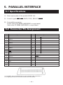
5. PARALLEL INTERFACE
5.1 Specifications
(1) Data input system: 8 bit parallel (DATA 1-8).
(2) Control signal: STB, ACK, BUSY, P.N.E., SELECT, RESET
(3) Compatible connector:
Printer side: 57LE-40360 (ANPHENOL or equivalent)
Cable side: 57-30360 (ANPHENOL or equivalent)
5.2 Connector Pin Assignment
Pin
1
STB
Signal Name
Pin
19
2
DATA 1
20
3
DATA 2
21
4
DATA 3
22
5
DATA 4
23
6
DATA 5
24
7
DATA 6
25
8
DATA 7
26
9
DATA 8
27
10
ACK
28
11
BUSY
29
12
P.N.E.
30
13
SELECT
31
RESET *1
14
GND
32
FAULT *2
33
GND
15
16
GND
34
17
FRAME GND
35
18
Signal Name
TWISTED PAIR GND
TWISTED PAIR GND
36
*1: For RESET signal, Enable/Disable can be selected by DIP switch No. 3.
*2: Changing the internal resistance enables H/L level (fixed).
— 23 —
5.3 Description of Input/Output Signals
(1) Input signal
• DATA 1 to DATA 8 . . . 8 bit parallel signal (positive logic)
• STB . . . Strobe signal for reading out data (negative logic)
• RESET . . . Signal for resetting the entire unit (negative logic 4 ms or more)
(2) Output signal
• ACK . . . 8 bit data signal for requesting data. ACK is issued at the end of the
BUSY signal (negative logic)
• BUSY . . . Signal indicating the printer is busy. Input new data when the signal
is in “LOW” condition (positive logic)
• SELECT . . . Signal to indicate this equipment is in the SELECT (ready for
communication) state (positive logic)
“LO”is output in the state deselected by the operation panel (SELSW), mechanical error, or memory error.
• P.N.E. . . . Signal to be output for paper-near-end
(3) Other
• GND . . . Ground commonly used in the circuit
• FRAME GND . . . Frame ground (case ground)
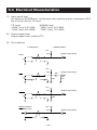
(4) Timing chart
POWER
DATA
DATA
DATA
DATA
STB
T2
T1: 1.6 µs MIN
T2: 500 µS MIN
T3: 10 µs TYP
T1
BUSY
ACK
T3
Busy signal timing: Clear timing can be selected by the memory switch.
ACK signal timing: The following kinds of timing can be selected by the memory
switch setting.
BUSY
Before
ACK
T4
BUSY
Center
ACK
BUSY
After
ACK
T5
— 24 —
T4: 5 µs TYP
T5: 5 µS TYP
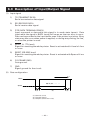
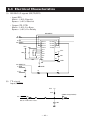
5.4 Electrical Characteristics
(1) Input signal level
All inputs are HCMOS level. As the input side is pulled up with a resistance of 3.3
kΩ, it can be used at TTL level.
TTL Level
“HIGH” level: 2.0 V MIN
“LOW” level: 0.8 V MAX
HCMOS Level
“HIGH” level: 4.0 V MIN
“LOW” level: 1.0 V MAX
(2) Output signal level
Output signal level is held at TTL.
(3) I/O conditions
< HOST SIDE >
< PRINTER SIDE >
VCC
DATA
3.3k
(HC04 or equivalent)
VCC
3.3k
(HC04 or equivalent)
100
STB
102
471
VCC
3.3k
(HC04 or equivalent)
RESET
104
OUTPUT SIGNAL
ACK BUSY P.N.E.
VCC
3.3k
— 25 —
(HC04 or equivalent)
6. SERIAL INTERFACE
6.1 Specifications
(1) Synchronization: Asynchronous
(2) Baud rate
1200, 2400, 4800, 9600, 19200 Baud/sec (User selection)
(3) Word configuration
• Start bit: 1 bit
• Data bit: 7 bits or 8 bits (User selection)
• Parity bit: odd, even, no parity (User selection)
• Stop bit: 1 bit or more
(4) Signal polarity
RS-232C
• Mark = Logic “1” (−3 V to −12V)
• Space = Logic “0” (+3 V to +12 V)
Selecting presence or absence of signal is available with TTL (RESET) DIP switch
No. 3.
• H level = Logic “1”
• L level = Logic “0”
(5) Receive data (RD)
• Mark: “1”
• Space: “0”
(6) Transmit data (TD)
• Mark: “1”
• Space: “0”
(7) Received control data (DTR) (DTR signal)
• Mark: Data transmission not possible
• Space: Data transmission possible
— 26 —
6.2 Connector Pin Assignment
Pin
Signal Name
Signal Direction
Host-Printer
Function
RS-232C
1
FG
Frame ground
7
GND
Signal ground
O
2
TD
←
Transmit data
O
O
3
RD
→
Receive data
O
20
DTR
←
Printer BUSY signal
O
23
RESET (L)
→
TTL Reset signal *1
25
RESET
→
Reset signal *1
*1: Enable/Disable of RESET signal can be selected by DIP switch No. 3.
In addition, changing the internal resistance allows selection of pin 23/pin 25.
In Factory setting, pin 23 (TTL Reset) is set.
Note: 1. Signals for RS-232C are based on EIA RS-232C level.
Applicable connector (D-sub connector)
Printer side: 17LE-13250 (Anphenol or equivalent)
Cable side: 17JE-23250 (Anphenol or equivalent)
— 27 —
TTL
O
O
6.3 Description of Input/Output Signal
(1) Input signal
1)
TD (TRANSMIT DATA)
Serial transmission data signal.
2)
RD (RECEIVE DATA)
Serial receive data signal.
3)
DTR (DATA TERMINAL READY)
Input command or data while this signal is in ready state (space). Data
input while the signal is BUSY (mark) will cause an overrun error to occur.
Data can be provided to the input buffer even if the printer is printing. Busy
state may also occur when power is applied, or during test printing, on-line,
or when the printer is reset.
4)
RESET (L) (TTL level)
Signal for resetting the whole printer. Reset is activated with L level of 4 ms
or more.
5)
RESET (RS-232C level)
Signal for resetting the whole printer. Reset is activated with Space of 4 ms
or more.
6)
FG (FRAME GND)
Case ground.
7)
GND
Signal ground for the circuit.
(2) Data configuration
t
Mark
b0, b1, b2 • • • • •
Space
(1)
(2)
(1) Start bit (1 bit)
(2) Data bit (8 bits)
(3) Stop bit (more than 1 bit)
— 28 —
(3)
6.4 Electrical Characteristics
(1) RS-232C I/O signals (RD/TD/DTR)
• Input (RD)
Mark = (−8 V): Stop bit
Space = (+8 V): Start bit
• Output (TD, DTR)
Mark = (−8 V): For Busy
Space = (+8 V): For Ready
SP232ENC
2: TD
20: DTR
3: RD
25: RESET
VCC
13
R1 in
8
R2 in
11
T1 in
10
T2 in
1
C1+
3
C1−
4
C2+
5
C2−
2
V+
6
V−
104
104
104
12
R1 out
9
R2 out
14
T1 out
7
T2 out
VCC
16
104
15
GND
104
23: RESET(L)
7: GND
1: FG
GND
0
0
(2) TTL circuit
Input (RESET)
VCC
3.3k
(HC04 or equivalent)
23 : RESET
Set to LOW when reset.
104
— 29 —
6.5 Error Detection
●
Communication error
• Parity error
Parity error occurs when parity check is specified and parity is not observed in
the even and odd parity checks.
• Framing error
When space state detected on detection of stop bit.
• Overrun error
When next following data having been transferred to receiving buffer register
regardless of presence of data in that receiving buffer register.
RECEIVING CONTROL AND BUFFERING
This equipment controls, on receipt of print data, receiving (DTR Control) in one-word
unit. If the host disregards DTR and carries out data transmission at this time, overrun of receiving data may be resulted. This state should be avoided on the host’s
responsibility. (The data discharging type host cannot follow this.) This is applicable
when the host adopts a double buffer type transmitter.
— 30 —
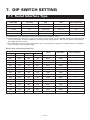
7. DIP SWITCH SETTING
7.1 Serial Interface Type
Switch No.
1
*1
*1
Function
Character direction
OFF
Normal
ON
Inverted
Factory Setting
OFF
2 (3110)
CR
—
—
OFF
2 (910)
CR
Ignore CR
CR + LF
OFF
3
Reset in
Disable
4
Bit length
8 bits
*2
*3
Enable
ON
7 bits
OFF
*1: A difference is developed by the emulation set by the memory switch.
*2: After setting DIP switch No. 4 to ON, turning the printer power on with the SEL switch pressed and held
causes the printer to enter the Manual memory switch setting mode. With normal power on operation,
bit length setting is active.
*3: This setting may cause some restrictions such as limiting the argument of control code or incomplete
format of data in bit image printing.
Baud rate and parity selection
8
OFF
Switch No.
7
6
OFF
OFF
5
OFF
None
4800
O
OFF
OFF
OFF
ON
None
1200
—
OFF
OFF
ON
OFF
None
2400
—
OFF
OFF
ON
ON
None
4800
—
OFF
ON
OFF
OFF
None
9600
—
OFF
ON
OFF
ON
None
19200
—
OFF
ON
ON
OFF
Odd
1200
—
OFF
ON
ON
ON
Odd
2400
—
ON
OFF
OFF
OFF
Odd
4800
—
ON
OFF
OFF
ON
Odd
9600
—
ON
OFF
ON
OFF
Odd
19200
—
ON
OFF
ON
ON
Even
1200
—
ON
ON
OFF
OFF
Even
2400
—
ON
ON
OFF
ON
Even
4800
—
ON
ON
ON
OFF
Even
9600
—
ON
ON
ON
ON
Even
19200
—
Parity
— 31 —
Baud Rate
Factory Setting
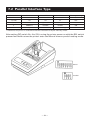
7.2 Parallel Interface Type
Switch No.
1
Function
Character direction
2 (3110)
CR
2 (910)
CR
3
RESET in
Disable
Enable
ON
4
Memory switch
Disable Setting
Enable Setting
OFF
*
*
OFF
Normal
ON
Inverted
Factory Setting
OFF
CR
LF
OFF
Ignore CR
CR + LF
OFF
*: Difference may occur in accordance with the emulation set by the memory switch.
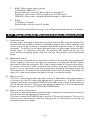
After setting DIP switch No. 4 to ON, turning the printer power on with the SEL switch
pressed and held causes the printer enter the Manual memory switch setting mode.
Serial
Parallel
— 32 —
8. PRINT CONTROL FUNCTION
8.1 List of Control Codes
LF
Code
Function
(Hexadecimal)
0A
Line feed after print
CR
0D
Carriage return and line feed
O*1
O*1
SI
0F
Normal size character
O
O
SO
0E
Double width character
O
O
US
1F
Normal size character
O
—
RS
1E
Double width character
O
—
CAN
18
Cancel data
O
—
DC2
12
Inverted character
O
—
DC1
11
Initialize
O
—
ESC + “B”
1B, 42
Feed paper continuously
O
O
ESC + “R”
1B, 52
Select international character
O
O
ESC + “t”
1B, 74
Select code page
O
O
ESC + “/”
1B, 2F
Register sentence
O
—
ESC + “! ”
1B, 21
Print registered characters
O
—
ESC + “&”
1B, 26
Register user-defined character
O
O
ESC + “%”
1B, 25
Enable/Disable registered characters
O*2
O*2
ESC + “K”
1B, 4B
Print bit image
O
O
FS + “W”+ 1
1C, 57, 1
Double height and width character
O
—
FS + “W”+ 0
1C, 57, 0
Clear double height and width character
O
—
ESC + “A”
1B, 41
Set line spacing
—
O
DC4
14
Clear double width character
—
O
DC3
13
Power down function
—
O
DC2
12
Power down function
—
O
Change memory switch
O
O
Symbol
ESC + “) ” +
1B, 29,
55(H) + n1 + n2 + AAH 55, n1, n2, AA
CBM910
iDP3110
O*1
O*1
*1: Invalid in some case. Refer to the descriptions for LF and CR in Control Code Details.
*2: Invalid in some case. Refer to the descriptions for Valid/Invalid of use-defined characters in Control
Code Details.
— 33 —
8.2 Control Code Details
(1) Command for Line Feed After Printing (CR/LF)
By entering CR (0DH)/LF (0AH) codes, data in the print buffer is printed followed
by a line feed. Without data in the print buffer, only a line feed is performed.
This command is ignored just after buffer full in case of 910 emulation.
CR and LF are valid in the following conditions.
910 Emulation
Serial
DS2-ON
CR and LF
DS2-OFF
LF only
Parallel
CR and LF
LF only
Serial
DS2-ON
CR only
DS2-OFF
CR only
Parallel
LF only
CR only
3110 Emulation
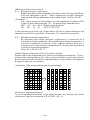
(2) SI/SO and US/RS Commands
SI/SO codes function in the same manner as US/RS as long as 8-bit data are
assigned (serial communication data bit length), which, however, are divided,
under 7-bit assignment, into SI (20H~7FH characters) print assignment and SO
(A0H~FFH characters) print assignment functions.
1.
Standard letter assignment (SI/US) command:
With SI (0FH)/US (1FH) codes input, lateral enlargement is cancelled and
the data following are printed in standard letters. This command can cancel
only lateral enlargement, which dose not apply to ×4 enlargement.
— 34 —
2.
Laterally enlarged letter assignment (SO/RS) command:
With SO (0EH)/RS (1EH) codes input in any columns, the data following are
printed in prints enlarged double in width.
Although standard and enlarged letters can be mixed within one line,
automatic (buffer-full) printing takes place when the number of columns
reaches 24 (or 40) counted in standard letters. With 910 emulation, laterally
enlarged letter assignment is cleared by printing after line feed, followed
by SI, US, and DC1. With 3110 emulation, it is cleared by printing after line
feed by LF and CR, followed by SI, US, and DC4.
[Receiving Data]
SO
1234567890
SO
123
SI
SO
123
SI
SO
SO
CR
ABCD
ABCD
CR
SO
12
CR
12345678901B
[Results of Printing]
123456789
123ABCD
123ABC12
A12345678901B
(3) Data Cancel (CAN) Command
With CAN (18H) code input, print data held within the line before input of the
CAN code are all cancelled.
[Receiving Data]
SO
123456
CAN
ABC
CR
[Results of Printing]
ABC
* As data “123456” are cancelled without the command “SO” cancelled, “ABC”
is printed in lateral enlargement.
— 35 —
(4) Inverted Letter Assignment (DC2) Command
When data are input with DC2 (12H) attached at the beginning of a line (invalid
when attached to any other place), data following are all printed in inverted letters.
To cancel this, input either DC2 again or DC1 (initial setting.)
(5) Initial Setting (DC1) Command
With DC1 (11H) input, various conditions set after power supply are cancelled
and the state as at supply of power is restored.
Content of the input buffer, however, is held unchanged.
(6) Power Down Function (DC2, DC3) Only when 3110 emulation is selected
In order to reduce power consumption when printer is waiting for the operation,
2 power down modes triggered by the codes DC2 and DC3 are incorporated into
this product. When the printer receives power down commands (DC2 or DC3), it
switches to the power down mode after all entered data is printed out.
a)
DC2 (12H)
Unit switches to power down mode when DC2 code is entered.
Operation of the oscillator is not terminated.
[Power down release]
(a-1) RESET input
By applying “LOW” pulse to the RESET terminal for more than 4 ms,
the power down mode is cleared, thereby switching the unit to
operational condition approximately 500 ms after initialization.
b)
DC3 (13H)
Unit switches to power down mode when DC3 code is entered.
Operation of the oscillator is terminated, reducing the power consumption
to less than that of the DC2 power down mode.
(b-1) RESET input
By applying “LOW” pulse to the RESET terminal for more than 4 ms,
the power down mode is cleared, thereby in HIGH-level switching
the unit to operational condition approximately 500 ms after
initialization.
— 36 —
(7) Continuous Paper Feed Assignment (ESC + “B” + n) Command
With ESC (1BH) +“B” (42H) + n code input, continuous paper feed at n-dot line is
executed.
However, n allows continuous paper feed to be executed at even-numbered dot
line in the range of 4 ≤ n ≤ 255. If n is specified otherwise, this command is
cancelled.
When this command is entered, print data, if any, in the input buffer is printed.
Print line (10-dot line) is included in the amount of line feed “n”; therefore, 4 ≤ n
≤ 9 provides a line space of “0”.
(8) International Character Select (ESC + “R” + n) Command
By entering the code ESC (1BH) + “R” (52H) + n, characters input hereafter are set
to the characters for the following countries.
n
0
Country
U.S.A. (USA)
n
5
Country
Sweden (SWE)
1
France (FRA)
6
Italy (ITA)
2
Germany (GER)
7
Spain (SPA)
3
U.K. (U.K)
8
Japan (JPN)
4
Denmark (DEM)
With n other than those specified, the set value for the U.S. is assigned.
Note: At the printer power on or after RESET is applied, this setting differs
depending on the status of memory switch setting.
(9) Codepage Select (ESC + “t” + n) Command
By the entry of ESC (1BH) + ”t” (74H) + n code, the follwing character code table
can be selected.
n
0
Character Code Table
Codepage PC437
n
8
Character Code Table
Codepage PC857
1
2
Katakana
9
Codepage WPC1252
Codepage PC858
10
Codepage PC864
3
Codepage PC860
11
Codepage PC869
4
Codepage PC863
5
Codepage PC865
253
910 Emulation (Japan)*
6
Codepage PC852
254
910 Emulation (International)*
7
Codepage PC866
255
Space page (for user-defined characters)
*: In the factory setting, character set for model type is 910 Emulation (International) for
model F and 910 Emulation (Japan) for model J.
— 37 —
(10) Sentence Registration (ESC + “/” + n) Command
With input of ESC (1BH) + “/” (2FH) + n + ‘registered sentence’ code, 24 (40)-bytes
data following n are registered. Set a numeral of 1~8 to n.
With any other numeral having been set, data following are regarded as normal
printing data, where no registration takes place and printing conducted.
Data cannot exceed one line which should be ended with CR (0DH) or LF (0AH).
To register sentences exceeding 24 (40) bytes, sentence up to 24 (40) bytes are
registered, and the data following are printed out as printed data.
The ESC command cannot be registered.
(11) Registered Sentence Printing (ESC + “!” + n) Command
With ESC (1BH) + “!” (21H) + n code input, sentence already registered in the
numeral assigned to n are printed.
Assign, to n, a numeral of 1 to 8. With any other numeral having been set, no
execution takes place.
Note 1: As much as 24 (40) bytes of data can be registered. In case that 24 (40)
columns are exceeded on printing (because of enlarged or ×4 letters
having been assigned, etc.), printing is conducted up to 24 (40)th column
and the columns overflowed are printed in the next line. Be sure to
make registration in consideration of printing results.
Note 2: When double height and width character printing or inverted character
printing is executed in registered sentence printing, this setting is active
even after returning to normal printing unless that setting is cancelled.
Application Example
ESC
/
1
CR
This is a pen
Sentence registered in 1.
ESC
/
9
CR
It this a pen ?
No registration made with 9.
ESC
/
1
CR
Is this a pen
Overwritten on sentence
registered initially in 1.
ESC
!
1
Printing of sentence registered in 1.
— 38 —
<Registered State>
1
2
3
4
5
6
7
8
It is pen
<Printing Result>
Is this a pen ?
It is a pen
(Printed out with ESC + “!” + 1)
(12) Character Registration (ESC + “&”) Command
1.
For 24-column model (ESC + “&” + A1 + A2)
Individual patterns can be registered by entering the code ESC (1BH) + ”&”
(26H) + A1 + A2, then entering the pattern data.
A maximum of 224 characters can be registered, and any address in the
range of 20H to FFH can be used for the registration. However, if a new
pattern is registered in an address already in use, existing data is cleared
and the newly entered data becomes valid.
[Address setting]
Specified address is matched to the character code and can be accessed
likewise to the stored fixed character record. If a fixed character is defined
in the specified address, the fixed character becomes invalid.
A1 signifies the starting address for the registrations, A2 is the ending
address.
— 39 —
[Method of data transmission]
d-1) Single character registration
Select the address to be defined (character code) from among 20H to
FFH and designate is as A1. When registering a single character,
starting and ending addresses match each other. That is, A1=A2.
<Example>
A 6 × 6 dot matrix full dot pattern is to be registered in address 41H
(code for the fixed character “A”. (Numerals are hexadecimal.)
ESC + “&” + A1 + A2 + “Pattern data (6 bytes)”
1B
36
41 41
FF FF FF FF FF FF
In the successive controls, a 6 × 8 dot matrix full dot is output whenever the
character code 41H is specified. (Character “A” cannot be accessed.)
d-2)
Multiple character registration
By repeating the single character registration, a maximum of 8
characters can be registered. When defining multiple characters in a
successive address (character code), register pattern data for a
maximum of 8 characters by designation A1 as the starting address
and A2 as the ending address.
Note: A1 < A2, A2 – A1 ≤ 7
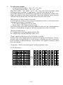
[Pattern data configuration] (For 24-column model)
Pattern data to be registered must consist of 6 bytes per character. That is,
pattern data configured by a 6 × 8 dot matrix is broken up into 6 vertically
positioned units each of which is represented by 1 byte of data. All together,
6 bytes of data are transmitted.
<Example> When transmitting the following data:
1
2
3
4
5
6
1
2
3
4
5
6
0
1
2
3
4
5
6
7
[Printing of registered letters]
To print registered character, in the same manner as printing other fixed
characters, use the commands (CR, LF, ESC + B + n).
— 40 —
2.
For 40-column model
In 910 emulation (ESC + “&” + C1 + A1 + A2)
In 3110 emulation (ESC + “&” + A1 + A2)
With ESC (1BH) + ”&” (26H) + {C1} + A1 + A2 code and the pattern data
following input, a pattern is registered. Only 910 emulation for { }.
Total 224 characters are available for registration into addresses of 20H~FFH.
When two pattern data have registered in the same address, those initially
registered are cleared and the new data alone are made valid.
[Recognition of use of upper most bit]
For recognition of use or non-use of the uppermost bit by a character to be
registered, set data to Parameter C1.
C1=0 (00H): Uppermost bit not used.
Other than C1=0: Uppermost bit used.
With 0 set to this parameter while the uppermost bit is in use, ×4 enlargement
results in incomplete images for which the uppermost part is lacking.
[Setting of addresses]
A1 : Registration starting address (20H~FFH)
A2 : Registration ending address (20H~FFH)
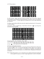
[Pattern data configuration] (For 40-column model)
Pattern data to be registered must consist of 9 bytes per character. That is,
pattern data configured by 9 × 8 dot matrix is broken up into 9 vertically
each of which is represented by 1 byte of data. All together, 9 bytes of data
are transmitted.
<Example> When transmitting the following pattern data:
In 910 emulation
1
2
3
4
5
6
7
8
9
1
0
2
3
4
5
6
*
*
*
*
*
*
7
8
9
1
2
3
4
5
6
7
41H 22H 55H 08H 41H 00H 41H 00H 00H
— 41 —
In 3110 emulation
1
2
3
4
5
6
7
1
2
0
3
4
5
6
*
*
*
*
*
*
7
1
2
3
4
5
6
7
41H 22H 55H 08H 41H 00H 41H
As this printer takes half-dot printing system, dots cannot be aligned
continuously in printing (horizontal) direction. Therefore, even if any pattern
is specified at point “*” at the right of point “●” above, it cannot be registered
as a pattern.
Configuring a double width character by registering the data for 2 characters
is also possible.
<Example> When registering a Japanese character “ ” by using two
characters 41H and 42H
1
2
3
4
5
6
7
8
9
41H
1
2
3
4
5
6
7
8
9
42H
Following ESC + & + 01 (Note) + 41H + 42H
sending data 80H, 00H, 81H, 00H, 89H, 00H, 89H, 00H, FFH
00H, 89H, 00H, A9H, 40H, 81H, 00H, 80H, 00H
allows “ ” to be registered at 41H and 42H.
[Printing registered character]
To print a registered character, executing Activate Registered Character
command (ESC + “%” + 1) may be required in some case. If you want to
return to the internal characters, it is necessary to disable the registered
characters. Refer to the description for Valid/Invalid of Registered Characters
command.
Note: With 0 being set in “C1” parameter even if data have been registered
in the uppermost position, letter image registered is made incomplete.
— 42 —
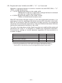
(13) Registered Letter Valid/Invalid (ESC + “%” + n) Command
Whether a registered pattern is valid or invalid is set with ESC (1BH) + ”%”
(25H) + n code being input.
n = 1 (01H): Registered pattern to be made valid.
(Addresses for which no registration change has been conducted
are taken as inside fixed characters.)
n = 0 (00H): Registered pattern to be made invalid.
(Taken as inside fixed character sets.)
With 910 emulation 40-digit version, to use the registered characters, it is
necessary to set the registered characters to be valid using this command.
With 3110 emulation and 910 emulation 24-digit version, the registered
characters are valid at the registration of the user-defined characters without
setting the registered characters to be valid.
To reset to the state where inside fixed characters are usable while registered
characters are valid, it is necessary to disable the registered characters.
Command for setting to invalid operates regardless of the emulation or
number of digits.
Registered Characters Enable/Disable Command
910 Emulation (40 digits)
Set to Valid
O
Set to Invalid
O
910 Emulation (24 digits)
×
O
3110 Emulation (40 digits)
×
O
3110 Emulation (24 digits)
×
O
O: Operation enabled by the Valid/Invalid command of registered characters.
×: As the registered characters are valid by the Register User-defined Character
command, it is not necessary to set the registered characters to be valid.
— 43 —
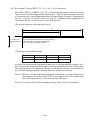
(14) Bit Image Printing (ESC +“K”+ n1 + n2 + n3) Command
With ESC (1BH) + K (4BH) + n1 + n2 + n3 code being input, conversion from
Text mode into Bit Image mode takes place. The n1/n2/n3 assigns amount
of transmission of bit image data which follows these. Where, n1 represents
the no. of bytes in lateral direction and n2 (lowermost)/n3 (uppermost)
represent the no. of dot lines in vertical direction.
(Relations between data and print-out)
n1
1 byte
D8
n3 × 256 + n2
No. of dot lines
D7
D6
D5
D4
D3
D2
D1
D1~D8 indicate dot location in each position.
To place a dot in a particular position,
put 1 in binary and 0 for a space.
(Parameter assignable range)
Model
24 columns
n1
1~18
n2
0~255
n3
0~1
40 columns
1~23
0~255
0~1
In case that assignment has been made out of the assignable range or n2 =
n3 = 0 has been assigned, Bit Image mode is cancelled and Text mode starts.
With this printer, on completion of read-in of 4-dot-line data or on completion
of n1/n2/n3 assigning data, lacking data are printed as spaces.
Note 1: With n1 = 23 having been assigned in 40-column model, 4 dots from
the lowermost column (LSC-DOT) are made invalid. This is because
the printing position in one line equals 180 dots.
Note 2: On termination of bit image printing, Text mode is reinstated.
— 44 —
(15) ×4 Enlarged Letter Assignment (FS + “W” + 1) Command
FS (1CH) + “W” (57H) + 1 (01H) code input, ×4 enlarged letters are assigned.
Data following this code are printed vertically and laterally twice enlarged.
(16) ×4 Enlargement Cancel (FS + “W” + 0) Command
With FS (1CH) + “W” (57H) + 0 (00H) code being input, ×4 enlargement
assignment is cancelled.
Note 1: Although standard and laterally enlarged letters can coexist in one
line, automatic (buffer-full) printing takes place on reaching to 24th
(40th) column counted in standard characters.
Note 2: With ×4 enlargement and double-width having been assigned, ×4
enlargement has priority.
Application Example)
[Receiving Data]
1C
1C
1C
W
W
W
1
0
0
123456789
CR
ABC 1C W 1 123 CR
A 1C W 1 12345678901B
<Printing Results>
123456789
ABC123
A1234567891B
The last letter, although in ×4 assignment, is printed
in standard letter since it being in the 24th column.
(For 40 column mechanism, this applies to the 40th
column.)
(17) Set Line Spacing (ESC + “A” + n) Command
Sets a line space of “n2” dot line by the entry of ESC (1BH) + “A” (41H) + n
code. Initial setting is 2-dot line space.
Here, n is an even number in the range of 0 ≤ n ≤ 255.
Note: When an odd number is set to n, a line space of n−1 dots is specified.
When n=0 or 1 is specified, continuous printing is permitted.
— 45 —
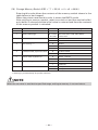
(18) Change Memory Switch (ESC + “)” + 55 (H) + n1 + n2 + AA(H))
Entering this code allows the contents of the memory switch shown in the
table below to be changed.
When the printer receives this code, it enters the BUSY mode.
After writing to memory switch, reset is carried out and the receive buffer/
print buffer is cleared and the initial value is restored and then the contents
of the memory switch is reloaded.
n1
0
Function
Select international character set
1
Select code page.
2
Select 910/3110 emulation
3
n2
0~8
0~11, 253,
254, 255
ACK timing *1
Content of Setting
See International Character Code Table.
See Character Code Table Select
Command.
0
910 Emulation
1
3110 Emulation
0
Before
1
Center
2
After
Enable (Valid)
4
Enable/Disable paper-near-end
0
1
Disable (Invalid)
5
Online state at power on
0
Select (Online)
1
Deselect (Offline)
6
BUSY timing *1
7
Buffer Size (Serial I/F)
0
Standard
1
CBM-910
0
2k bytes
1
72 bytes
*1: Setting is permitted only for parallel interface.
NOTE
When the set value is outside the specified range, writing to memory is not carried out.
— 46 —
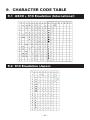
9. CHARACTER CODE TABLE
9.1 ASCII + 910 Emulation (International)
9.2 910 Emulation (Japan)
— 47 —
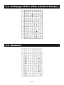
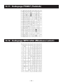
9.3 Codepage PC437 (USA, Standard Europe)
9.4 Katakana
— 48 —
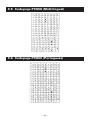
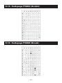
9.5 Codepage PC858 (Multilingual)
9.6 Codepage PC860 (Portuguese)
— 49 —
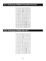
9.7 Codepage PC863 (Canadian-French)
9.8 Codepage PC865 (Nordic)
— 50 —
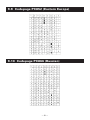
9.9 Codepage PC852 (Eastern Europe)
9.10 Codepage PC866 (Russian)
— 51 —
9.11 Codepage PC857 (Turkish)
9.12 Codepage WPC1252 (Windows Latin1)
— 52 —
9.13 Codepage PC864 (Arabic)
9.14 Codepage PC869 (Greek)
— 53 —
9.15 International Character Code Table
— 54 —
— 55 —
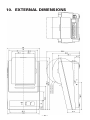
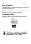
60 Dia. Paper Roll
80 Dia. Paper Roll
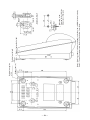
10. EXTERNAL DIMENSIONS
— 56 —
Wall mounting hole
2 Rubber foot guide height
Rubber foot height
3.5
Mounting screw
Drawing for Installation
Dimensions (Remarks)
Details A-A (2/1)
Note 1: Drawings above indicate the bottom and side views of CBM-910 main body.
Note 2: The wall hanging screw head shall be below 3 mm long.
Rubber foot (4)
Rubber foot guide
φ15.4
— 57 —
1.04E-0503 Printed in Japan