1
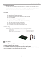
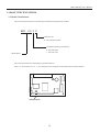
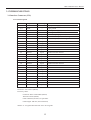
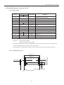
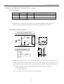
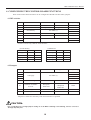
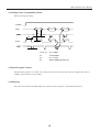
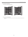
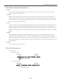
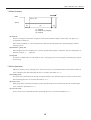
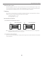
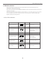
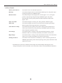
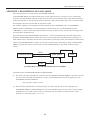
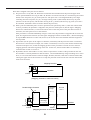
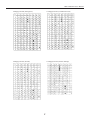
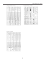
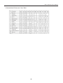
User’s Manual
CONTROL BOARD FOR LT-122x/132x
MODEL BD2-1220/1221
Rev. 02 Newly issued Jun. 10th, 2001
REVISION
Rev.No.
Rev.02
Date
Jun. 10th, 2001
Content
Newly issued
i
GENERAL PRECAUTIONS
Prior to using the Control Board BD2-1220/1221, be sure to read this User’s
Manual thoroughly. Please keep it handy so that you can refer to it whenever
necessary.
1.
2.
3.
4.
5.
6.
7.
8.
The information contained herein may be changed without prior notice.
Reproduction of part or all of the User’s Manual without permission is strictly prohibited.
Never service, disassemble, or repair parts that are not described in the User’s Manual.
Note that CBM shall not be responsible for any damages attributable to incorrect
operation/handling or improper operation environments, which are not specified in the
User’s Manual.
Operate this control board only in the manners as described in the User’s Manual;
otherwise, accidents or problems could possibly occur.
Data are basically temporary; they cannot be stored or saved for a long time or
permanently. Please note that CBM shall not be responsible for any damages or lost
profits resulting from the loss of data attributable to accidents, repairs, tests, and so on.
If you have any questions, or notice any clerical errors or omissions regarding the
information in the User’s Manual, please contact your CBM dealer.
Please note that CBM shall not be responsible for any results or effects resulting from
operation of this control board even if the information in the User’s Manual is properly
observed.
SAFETY PRECAUTIONS
— WHICH SHOULD BE STRICTLY OBSERVED
In order to help prevent safety hazards to operators or any other persons and
damages to property, special warning symbols are used in this User’s
Manual to indicate important items to be strictly observed. The following
describes possible hazards that could result from abuse of this product or
negligence of the safety cautions:
WARNING
Negligence of the precautions indicated by this symbol may
result in death or serious injuries.
CAUTION
Negligence of the precautions indicated by this symbol may
result in injuries or damages to property.
This is a symbol mark used to alert your attention to important items.
ii
WARNING
● Never handle the Control Board BD2-1220/1221 in the manners descried below;
otherwise, it may be damaged, get out of order or overheated, possibly causing smoke,
fire or electric shock.
● If the control board is damaged or breaks down, be sure to turn off the power, disconnect
the power plug from the wall outlet, and contact your CBM dealer.
• Do not allow the control board to be subjected to any strong impact or shock, such as stamping, hitting,
dropping, and the like.
• Install the control board in a well-ventilated place. Do not use the control board in such a manner that its
ventilation slots are blocked.
• Do not install the control board in a place like a laboratory where chemical reactions are expected, or in a
place where saltish gases are present in the atmosphere.
• Use the control board only on the specified voltage and frequency. Otherwise, fire or smoke generation may
occur.
• Do not connect/ disconnect the power cord or data cable by holding the cable.
Do not pull or carry the control board in such a manner that undesirable force is applied to the cables.
• Do not drop or insert any foreign substances, such as paper clips or pins, into the control board.
• Do not spill any liquid on or spray any chemical-containing liquid over the control board. If you spilled water
or any other liquid onto this product, immediately shut off power supply and contact your CBM dealer.
• Do not disassemble or modify the control board in any manner; otherwise, a fire or electric shock may result.
• Do not place the equipment where it can be easily touched during operation. Otherwise, possible shock or
static build-up may cause fire or damage to the control board electronics.
PRECAUTIONS FOR INSTALLATION
• Do not use or store the Control Board BD2-1220/1221 in a place exposed to heat of fire, moisture or direct
sunlight, or in a place where the prescribed operating temperature and humidity are not met, or in a place
exposed to oily mist, iron powder or dust; otherwise, the control board may get out of order, emit smoke or
catch fire.
• Do not install the control board in a place like a laboratory where chemical reactions are expected, or in a place
where saltish gases are present in the atmosphere; otherwise, there may occur a danger of fire or electric
shock.
• Install the control board on a horizontal, sturdy table in a place provided with proper ventilation and free from
any vibration. Do not install in an unstable place, as this may lead to equipment failure.
• Do not use the control board near a radio or television receiver. Avoid sharing an electrical outlet with a radio or
television receiver, or this may cause a reception problem.
• Never connect the grounding cable to a gas pipe, or this may lead to a danger of explosion.
• Be sure to turn off the power of the control board and the host computer connected before connecting or
disconnecting the cables; always hold both plug and cable. Do not use or wire the control board in such a
manner that an undesirable load is applied to the cables.
• Connect the connector cables correctly and securely.
• Use shielding wires or twist paired wires for signal lines in order to minimize the effects from noise. Do not
extend the data cable too long.
• Do not connect the data cable to noisy equipment.
• In case of emergency, always place the control board so that it is easily disconnected from the power source.
iii
PRECAUTIONS FOR HANDLING
Observe the following precautions to use the Control Board BD2-1220/1221 correctly and
avoid troubles from occurring.
• Use only the rated supply voltage specified for this product.
• Exercise care not to drop any metallic foreign object onto this product.
• Do not spill any liquid on the control board, or spray it with any chemical-containing liquid.
• Do not stamp on, drop, hit, or impart any strong shock to the control board.
• Wirings to other devices should be carefully established to avoid cross connections which may damage not
only the control board itself, but other system devices attached to it.
• This product should only be used with the specified peripheral devices.
• Do not use the control board in a place where it can easily come into contact with the hands.
• This product contains devices that are sensitive to electrostatic damage. When handling, keep any source of
static electricity away from the control board.
• Do not connect this product to, or install it in the vicinity of, any equipment that is the source of
electromagnetic noise. The control board may have an adverse affect on any attached peripherals. We
recommend you use some kind of noise insulating device with this equipment.
• This product can be reconfigured for non-default operation parameters. When using a soldering iron for
jumper reconnections, exercise care not to damage the adjacent parts. Also be sure to turn off the control
board before launching reconfiguration work.
• When reshipping this product, carefully pack it to protect it from vibration, deformation, or electrostatic
damage possible in transit.
To prevent injuries and associated damages:
• Should any abnormal condition occur while the control board is operating, stop it immediately and
disconnect the power plug from the wall outlet.
• This product may partially heats up as a result of extended use. Allow a sufficient time to cool off before
starting repair or maintenance work.
• In case of trouble, never attempt to repair the control board yourself. Be sure to call your dealer for servicing.
• Before using this product for the first time, please read the instructions throughout this manual.
iv
THE TABLE OF CONTENTS
1. GENERAL OUTLINE ........................................................................................................................ 1
1.1 Features ..................................................................................................................................................................... 1
1.2 Before using .............................................................................................................................................................. 1
2. BASIC SPECIFICATIONS ................................................................................................................ 2
2.1 Model Classification ................................................................................................................................................. 2
2.2 Basic Specifications .................................................................................................................................................. 3
2.3 Print Paper Specifications ......................................................................................................................................... 4
2.4 Thermal Print Head and Peripheral Devices ............................................................................................................ 4
3. INTERCONNECTION ....................................................................................................................... 5
3.1 Interface Connector (CN1) ....................................................................................................................................... 5
3.1.1 Pin Description .................................................................................................................................................. 5
3.1.2 Example of Power Connections ........................................................................................................................ 6
3.2 Print Head Interface Connector (CN2) ....................................................................................................................... 7
3.2.1 Pin Description .................................................................................................................................................. 7
3.2.2 Compatible FFC Cable ...................................................................................................................................... 7
3.3 Head-Up and Paper End Sensor Connectors (CN3 & CN7) .................................................................................... 8
3.4 Motor Connector (CN4) ........................................................................................................................................... 8
3.5 Auto Cutter Connector (CN5) .................................................................................................................................. 8
3.6 Paper Near-End Sensor Connector (CN6)
*Option .......................................................................................... 9
3.6.1 Pin Description .................................................................................................................................................. 9
3.6.2 Reference Schematic Diagram .......................................................................................................................... 9
4. CONFIGURING THE CONTROL BOARD FUNCTIONS ......................................................... 10
4.1 DIP Switches .......................................................................................................................................................... 10
4.2 Jumpers ................................................................................................................................................................... 10
4.3 Preset Jumper .......................................................................................................................................................... 11
5. POWER SUPPLY .............................................................................................................................. 12
5.1 Specifications ......................................................................................................................................................... 12
5.2 Precautions ............................................................................................................................................................. 12
6. PARALLEL INTERFACE ................................................................................................................ 13
6.1 Specifications ......................................................................................................................................................... 13
6.2 Description of Input and Output Signals ................................................................................................................ 14
6.2.1 Input Signals .................................................................................................................................................... 14
6.2.2 Output Signals ................................................................................................................................................. 14
6.2.3 Power related signal ........................................................................................................................................ 14
6.3 Electrical Characteristics ........................................................................................................................................ 14
6.4 Timing Chart (Compatibility Mode) ...................................................................................................................... 15
v
6.5 Data Reception Control .......................................................................................................................................... 15
6.6 Buffering ................................................................................................................................................................. 15
6.7 Connections to Parallel Port ................................................................................................................................... 16
7. SERIAL INTERFACE ...................................................................................................................... 17
7.1 Specifications ......................................................................................................................................................... 17
7.2 Description of Input and Output Signals ................................................................................................................ 18
7.3 Electrical Characteristics ........................................................................................................................................ 18
7.4 Data Structure ......................................................................................................................................................... 19
7.5 Error Detection ....................................................................................................................................................... 19
7.6 Data Reception Control .......................................................................................................................................... 20
7.7 Buffering ................................................................................................................................................................. 20
7.8 Connections to Serial Port ...................................................................................................................................... 20
8. ERROR HANDLING ........................................................................................................................ 21
8.1 List of Error indications .......................................................................................................................................... 21
8.2 Error Details ........................................................................................................................................................... 22
9. SPECIAL FUNCTIONS ................................................................................................................... 23
9.1 Page Print Mode ..................................................................................................................................................... 23
9.2 Test Printing ............................................................................................................................................................ 23
9.3 Hexadecimal Dump ................................................................................................................................................ 23
9.4 Software Revision .................................................................................................................................................. 24
9.5 Registering User-Defined Fonts and Logos ........................................................................................................... 24
10. PRINT CONTROL COMMANDS ................................................................................................ 25
11. BLOCK DIAGRAM ........................................................................................................................ 29
12. OUTLINE DRAWINGS FOR CONTROL BOARD .................................................................... 30
APPENDIX 1. DESCRIPTION OF PAGE MODE ..............................................................................A
APPENDIX 2. IDENTIFICATION OF SEND STATUS......................................................................C
APPENDIX 3. DEVICE ID ....................................................................................................................D
APPENDIX 4. CHARACTER CODES TABLE ................................................................................... E
1 Code page .................................................................................................................................................................... E
2 International Character Codes Table .......................................................................................................................... H
MAINTENANCE AND SERVICE ......................................................................................................... I
vi
BD2-1220/1221 User’s Manual
1. GENERAL OUTLINE
The BD2-1220/1221 Control Board is designed to operate the LT-1220/21 or LT-1320/21 Thermal Print
Mechanism from a PC. It incorporates maximum versatility that makes it applicable to diverse purposes.
Before using this product for the first time, read the instructions throughout this manual.
1.1 Features
(1) Ultra-compact design.
(2) Selectable serial or parallel printer interface.
(3) Support for both 80 mm (LT-132x) and 58 mm (LT-122x) print heads.
(4) Built-in input buffer.
(5) Bar-code Printing (Possible using special commands).
(6) Page Mode, which allows you to lay out pages freely.
(7) Registration of user-defined characters and logos into flash memory.
(8) Auto cutter mechanism provided as a standard unit.
(9) Paper End and Paper Near End sensors incorporated.
(10) Mounting hole geometry identical to those on the LT-122x.
1.2 Before using
After unpacking, make sure that the following items are included in the package:
Control Board: .............................................................. 1
Interface Cable: ............................................................. 1 (cable length 300 mm)
Ribbon cable for print head interface: .......................... 1 (cable length 100 mm)
CAUTION:
• Whenever plugging or unplugging a cable, be sure to remove power from the control board.
• Never short connector pins to each other.
• Use the power supply, LED lights, and interface within their specified ratings.
• Install the control board on a flat, sturdy table.
• Do not install the control board near a heater or in a place exposed to direct sunlight.
• Do not use the control board in a high-temperature, high-humidity, or heavily contaminated environment.
• Do not use the control board in an environment where condensation may occur. If condensation should occur,
leave the power turned off until condensation evaporates completely.
1
BD2-1220/1221 User’s Manual
2. BASIC SPECIFICATIONS
2.1 Model Classification
The control board models are classified by the following designation method:
BD2 - 122 0 U
Character Set
U : International model
Compatible printing mechanism:
0: LT-1220/1320
1: LT-1221/1321
Model Name
The control board has the following model identification:
Letter “U” and number “0” or “1” are stamped on the component side following the model number.
BD2122
Stamp location
2
BD2-1220/1221 User’s Manual
2.2 Basic Specifications
Model
Item
Print method
Paper width/printable
area width
Total number of dots
Dot density
Print speed
Paper feed span
Number of print
columns
Character size
Character type
Logo registration/print
Types of bar code
Line spacing
Interfacing
Input buffer
Sensors
Supply voltages
Current consumption
Thermal paper
BD2-122xU
Line thermal dot print method
LT-122x: Paper width: 58mm Printable area width: 54mm
LT-132x: Paper width: 80mm Printable area width: 72mm
LT-122x: 432 dots/lines
LT-132x: 576 dots/lines
8 dots/mm
MAX. 640 dot lines/sec
0.125mm
LT-122x: Font A: 36 columns Font B: 48 columns
LT-132x: Font A: 48 columns Font B: 64 columns
Font A: 1.25 × 3.00mm Font B: 0.88 × 3.00mm
Alphanumeric, International characters, symbols, Code 437, 850, 852,
857, 860, 863, 865, 866, Windows code, Katakana
Capable of registering user-defined characters and logos into flash
memory.
UPC-A/E, JAN (EAN) 13 columns/8 columns, ITF, CODABAR,
CODE39, CODE93, CODE128
4.23mm (1/6 inch) (Controllable with command)
Serial (RS-232C), Parallel (Centronics compliant)
4K bytes
Print head temperature, paper, head-up, and driving voltage sensors
Logic: 5V ±5% Approx. 200 mA (ANK slide printing)
Driver: 24V ±10% 0.7 A on average (For 12.5% of print area)
Print head: Approx. 5.2 A max. (for simultaneous 288-dot driving)
Approx. 0.52 A on average (For 12.5% of print area)
Motor: Approx. 0.4 A max. (Mean head resistance at 25°C and 640 pps)
Approx. 0.14 A on average
Thermal paper/thermal roll paper
Paper width: 58 mm (80mm) +0, –1mm
Paper thickness: 60 to 150 µm (Depending on mechanism)
5 to 40°C, 35 to 85%RH (No condensation)
Operating temperature
and humidity
Storage temperature and –20 to 60°C, 10 to 90%RH (No condensation)
humidity
Outside dimensions
90mm (W) × 65mm (D) × 20mm (H) (See the outline drawings.)
Weight
Approx. 40g (Control Board only)
3
BD2-1220/1221 User’s Manual
2.3 Print Paper Specifications
Use the recommended thermal papers listed below:
TF50KS-E2D (normal paper) from Nippon Paper
F230AA (normal paper) from Mitsubishi Paper or equivalent
* Paper thickness depends on the thermal head models.
* If an unspecified thermal paper is used, print tone may vary from the standard print tone.
* To preserve printed information for extended time period, carefully control temperature, humidity,
and other storage conditions.
* For the details of usable thermal papers, refer to the Specifications for each thermal print head.
* While you can use up to 150µm of paper thickness on some print heads, it is limited to 80 µm if the
auto cutter (ACS-220/230 Series) is used.
2.4 Thermal Print Head and Peripheral Devices
The control board supports the following thermal print heads and peripheral devices:
(1) Thermal print head
80-mm paper: LT-1320/1321
58-mm paper: LT-1220/1221
(2) Auto cutter
ACS-230/220 Series Auto Cutter
(3) Paper Near End sensor (optional)
* For more detailed specifications for these devices, refer to each User’s Manual.
4
BD2-1220/1221 User’s Manual
3. INTERCONNECTION
3.1 Interface Connector (CN1)
3.1.1 Pin Description
Pin No.
1, 2
3, 4
5~10
11~16
17
18
19
20
21
22
23
24
25
26
27
28
29
30
31
32
33
34
35
36
37
38
39
40
Signal Name Input/Output
Function
Vdd
—
Logic power supply (+5 V)
GND
—
Logic ground
Vp
—
Driver power supply (+24 V)
P-GND
—
Driver ground
nLF-SW
Input
LF switch input (paper feed)
nERROR
Output
ERROR LED output (direct diving)
nPEOUT
Output
PE LED output (direct driving)
DTR
Output
Serial interface DTR
TD
Output
Serial interface TD
RD
Input
Serial interface RD
DSR
Input
Serial interface DSR
DATA 0
Input
Parallel interface DATA 0
DATA 1
Input
Parallel interface DATA 1
DATA 2
Input
Parallel interface DATA 2
DATA 3
Input
Parallel interface DATA 3
DATA 4
Input
Parallel interface DATA 4
DATA 5
Input
Parallel interface DATA 5
DATA 6
Input
Parallel interface DATA 6
DATA 7
Input
Parallel interface DATA 7
nSTROBE
Input
Parallel interface STROBE
BUSY
Output
Parallel interface BUSY
nFAULT
Output
Parallel interface FAULT
SELECT
Output
Parallel interface SELECT
PE
Output
Parallel interface PE
nACK
Output
Parallel interface ACK
N. C
—
No Connection
N. C
—
No Connection
nRESET
Input
Parallel interface RESET
Connector: 53313-4015 (Molex)
Accessory cable:
Connector shell: 51089-4005 (Molex)
Terminal: 50212 (Molex)
Cable: AWG26 (UL1007) or equivalent
Cable length: 300 mm (not terminated)
*Prefix “n” to signal names denotes active Low signals.
5
BD2-1220/1221 User’s Manual
3.1.2 Example of Power Connections
* For the serial and parallel interface connections, see the sections dedicated to the respective
interface.
CN1
Vdd
+5V
GND
GND
5~
10
Vp
+24V
11 ~
16
P-GND
GND
1, 2
3, 4
Vdd
AC100 ~
240V
Regulated DC
power supply
10KΩ
CPU
17
LF SW
SW
1000pF
Supply GND or
CN1-3 (4)
+5V
330Ω
18
330Ω
19
ERROR LED
5V supply line or
CN1-1 (2)
PEOUT LED
Control Board
CAUTION:
(1) The ERROR and PEOUT LED lights have a current limiting resistor of 330Ω each to limit driving current to 10 mA.
An LED with forward voltage drop under 2 V should thus be used for these lights. A driving current exceeding 10
mA could damage the control board electronics.
(2) The logic power supply (Vdd and GND) may have supply and return connections only to a single pin each.
However, the driver power supply (Vp and P-GND) must be connected to all the available pins in order to secure
the specified drive current capacity.
(3) As shown above, the LF-SW input connection is a circuit that uses a ceramic capacitor to prevent chattering. You
can adjust the switch if chattering is severe.
(4) The RESET input is pulled up to Vdd with an on-board 3.3KΩ resistor. Leave it at NC if it will not be used.
(5) The serial interface uses RS-232C driver and receiver. Be sure to use RS-232C compatible signal levels for this
interface.
(6) Unused terminals should be insulated to keep exposed cable leads from them.
6
BD2-1220/1221 User’s Manual
3.2 Print Head Interface Connector (CN2)
3.2.1 Pin Description
Pin No.
1~4
5
6
7
8
9
10
11~19
20
21
22
23
24
25~28
Signal Name
Input/Output
Function
LT-122x LT-132x
Vp
—
Thermal head power supply
DO
Input
Serial print data input
CLK
Output
Data transfer clock
LAT
Output
Print data latch signal
N. C
STB 2
— (Output) N.C. (Strobe 2)
STB 1
Output
Strobe 1
TM
—
Thermistor
GND
—
GND
TM
—
Thermistor
Vdd
—
Thermal head driver power supply
STB 3 STB 4
Output
Strobe 3 (4)
STB 2 STB 3
Output
Strobe 2 (3)
D1
Output
Serial print data output
Vp
—
Connectors: CFF1128-0101 (SMK)
52045-2845 (Molex) or equivalent
* Note that the cable connector pin arrangement is in the reverse order to that on the control board.
The pin arrangement above is that on the control board.
* For the details of print head mechanisms, see the specifications for each model of print head.
3.2.2 Compatible FFC Cable
36.25 ± 0.1
1.25 ± 0.05
0.8 ± 0.03
7
Conductor side
MIn. 4
0.3 ± 0.05
Unit (mm)
7
Dimensions of
reinforcement plate
33.75 ± 0.1
BD2-1220/1221 User’s Manual
3.3 Head-Up and Paper End Sensor Connectors (CN3 & CN7)
Pin No.
LT-1x20 LT-1x21
CN3-1
—
CN3-2
CN7-1
CN3-3
CN7-2
CN3-4
CN3-4
CN3-5
CN3-5
CN3-6
CN3-6
CN3-7
CN3-7
Sensor
Signal Name Input/Output
Head-up
sensor
HU-A
GND
HU-C
PE-C
PE-K
PE-A
PE-E
Paper
sensor
Output
—
Input
Output
Input
Output
Input
Function
Head-Up signal input
Paper-End signal input
Connectors: 52045-0745 (Molex)
5597-04CPB (Molex)
53047-0210 (Molex) or equivalent
* For the LT-1x21, CN3 uses a 4-pin connector, and CN7 is shorted out with J12 (remove this jumper
if the platen open sensor is installed).
3.4 Motor Connector (CN4)
Pin No.
1
2
3
4
Signal Name
Motor A+
Motor B+
Motor A–
Motor B–
Input/Output
Output
Output
Output
Output
Function
Motor Drive signal A+
Motor Drive signal B+
Motor Drive signal A–
Motor Drive signal B–
Connectors: 53047-0410 (Molex)
3.5 Auto Cutter Connector (CN5)
Pin No.
1
2
3
4
Signal Name
M+
M–
GND
SW
Input/Output
Output
Output
—
Input
Function
Cutter Motor Drive signal M+
Cutter Motor Drive signal M–
GND
Cutter switch input signal
Connectors: 5267-04A-X (Molex)
CAUTION:
• You should use a ACS-220/230 series paper cutter.
• If you are not using the paper cutter, turn the Auto Cutter function on the DIP switch to the OFF position.
8
BD2-1220/1221 User’s Manual
3.6 Paper Near-End Sensor Connector (CN6) * Option
3.6.1 Pin Description
Pin No.
1
2
3
Signal Name
PNE-A
PNE-C
GND
Input/Output
Function
Output
Photointerruptor’s anode
Input
Photointerruptor’s collector
—
Photointerruptor’s cathode and emitter
Connectors: 5267-03A-X (Molex)
By default, pin 2 is tied to pin 3 with jumper J11 to deactivate the paper sensor (paper always
remains). If you need the Paper Near-End sensor function, obtain the connector above.
3.6.2 Reference Schematic Diagram
When Using a Photointerruptor
Vdd
Vdd
330Ω
1
68kΩ
100Ω
2
1000pF
3
33kΩ
Photointerruptor
(GP2S24)
Control Board
Paper
When Using a Switch
Sensor
1
NC
1 mm
2
SW
3
* The schematic diagram above is for a reflective photointerruptor. In this case the gap between the
sensor and paper surface should be approx. 1 mm. The electrical characteristics of the paper sensor
differ from one sensor model to another. Carefully study the specifications for the sensor you use.
* The control board has the following sensing threshold voltages (across pins 2 and 3):
0 to 0.4 V: Paper exists.
1 V or above: Paper end.
Paper sense status can not be guaranteed at any other voltage.
9
BD2-1220/1221 User’s Manual
4. CONFIGURING THE CONTROL BOARD FUNCTIONS
Some of the control board functions can be configured with DIP switches and/or jumpers.
4.1 DIP switches
No.
1
2
3
4
5
6
7
8
Function
Auto cutter
CR mode
ON
Available
LF Operation
Print density
OFF
Not available
Ignored
See Table (1).
Print head
Communication mode
LT-1200/1221
XON/XOFF
Baud rate
LT-1320/1321
DTR/DSR
See Table (2).
Factory setting
OFF
OFF
ON
OFF
ON
OFF
ON
OFF
Sections 6-8 are only valid for serial interface.
(1) Print density
Print density
Light
Standard
Slightly dark
Dark
3
OFF
ON
OFF
ON
(2) Baud rate
4
OFF
OFF
ON
ON
Baud rate
4,800bps
9,600bps
19,200bps
38,400bps
7
OFF
ON
OFF
ON
8
OFF
OFF
ON
ON
4.2 Jumpers
No.
J1
J2
J3
J4
J5
Function
Short
Code page
Open
See Table (3).
Auto loading
Valid
J6
Condition for BUSY
to occur
Reception
buffer full
J7
J8
Parity
Parity bit
Not available
Even
Invalid
• Off-line
• Reception
buffer full
Available
Odd
Factory setting
Short
Short
Short
Short
Short
Short
Short
Short
Jumpers J7 and J8 are valid only if the serial interface is specified.
CAUTION:
• Use a soldering iron to change jumper setting on J1-J8. When soldering or unsoldering, exercise care not to
damage adjacent parts.
10
BD2-1220/1221 User’s Manual
(3) Code Page
Code Page
PC437 (USA, EU Standard)
Katakana (Japanese)
PC850 (Multilingual)
PC860 (Portuguese)
PC863 (Canadian-French)
PC865 (Nordic)
PC852 (Eastern Europe)
PC866 (Russian)
PC857 (Turkish)
Windows Code
Not defined
Not defined
Not defined
Unused
Not defined
Blank page
J1
Short
Open
Short
Open
Short
Open
Short
Open
Short
Open
Short
Open
Short
Open
Short
Open
J2
Short
Short
Open
Open
Short
Short
Open
Open
Short
Short
Open
Open
Short
Short
Open
Open
J3
Short
Short
Short
Short
Open
Open
Open
Open
Short
Short
Short
Short
Open
Open
Open
Open
J4
Short
Short
Short
Short
Short
Short
Short
Short
Open
Open
Open
Open
Open
Open
Open
Open
* When Katakana is selected, the international character is set for Japanese. Otherwise, it is set for
USA.
* “Blank page” is an area for user registration, and is blank (Space) by default.
4.3 Preset Jumper
The control board allows the user to choose from serial and parallel interfaces:
PJ
Function
Interface
R side
Serial
P side
Parallel
Factory setting
P side
* The parallel interface is selected by default.
CAUTION:
• The input buffer size is fixed to 4K bytes.
• Serial data length is fixed to 8 bits.
• Printing rate decreases with print tone.
• The preset jumper setting remains valid until the control board is powered up next time or is reset.
11
BD2-1220/1221 User’s Manual
5. POWER SUPPLY
5.1 Specifications
Vdd: 5 VDC ±5%, approx. 200 mA
Vp: 24 VDC ±10%, approx. 0.7 A on average (approx. 6 A peak)
The data above is at 25°c and normal humidity.
AC is at 12.5% print area and 24 VDC. It varies with printing condition, operating
environment, operating condition, and some other factors.
5.2 Precautions
(1) Design the product to supply power to Vdd before Vp (within 100 ms) when power is supplied to this
control board.
(2) Design the product to turn off the power for Vdd after Vp when power is turned off.
(3) Make sure to turn off the power in case of connecting / disconnecting connectors.
(4) Make sure to use Vdd and Vp following their specifications.
(5) Make sure to use this control board connecting all of terminals between Vp and P-GND.
(6) The Vdd power supply should have a capacity to meet the current 0.2A or more.
(7) The Vp power supply should have a capacity enough to meet the peak current requirement.
CAUTION:
• A power supply not complying with the specified ratings may adversely affect print results.
• A power supply with insufficient peak current capacity may cause poor print quality or a low-voltage error.
• In case of emergency, always place the control board so that it is easily disconnected from the power source.
• The power supply should preferably be equipped with overvoltage protection, overcurrent protection, or other
protection features.
• The control board requires a dual supply voltage. Exercise care to avoid cross power connection as it may not only
damage the control board electronics but adversely affect the user or peripheral devices.
• If you feel odd smell during operation, immediately shut off the power to the device.
• The control board uses the same interface cable as that used with the BD2-2880. Care should be exercised as the
two boards require different supply voltages.
12
BD2-1220/1221 User’s Manual
6. PARALLEL INTERFACE
6.1 Specifications
Data transfer method: 8-bit parallel
Synchronizing method:Controlled by nStrobe signal externally supplied
Handshaking:
Handled by nAck and Busy signals
Signal level:
All signals are TTL compatible
Other control signals: PE, nFAULT, SELECT
* Bidirectional Parallel Interface (IEEE1284)
The control board supports the bidirectional parallel interface (IEEE-1284).
(1) Compatibility Mode (Host → Printer communication : Centronics compliant)
This control board provides Compatibility Mode, which specifies the Centronics interface
conventionally used for a wide variety of applications.
The control board is placed in this mode by default.
(2) Reverse Mode (Printer → Host communication)
Data transfer from the control board to the host computer is conducted in Nibble or Byte Mode.
The reverse mode has been devised to handle data transfer from an asynchronous printer controlled
by a host computer.
In Nibble Mode, data is transferred, 4-bits (a nibble) at a time, using existing control lines. In Byte
Mode, data is transferred by making 8-bit data lines bi-directional. Note that either mode cannot
work simultaneously with Compatibility Mode, thus resulting in half-duplex transmission.
To make Reverse Mode valid, pins 38 and 39 must be used as well as the parallel interface:
Pin 38: nAutoFD
Pin 39: nSelectIN
The bidirectional communications capability is not available unless these two pins are used. Leave
it at NC if it will not be used.
13
BD2-1220/1221 User’s Manual
6.2 Description of Input and Output signals
6.2.1 Input signals
• DATA 0~7:
An 8-bit parallel signal. (Active “High”)
• nSTROBE:
A strobe signal to help read 8-bit data. (Active “Low”)
• nRESET:
Resets the control board (active “Low”).
6.2.2 Output signals
• nACK:
An 8-bit data request signal, which is output at the end of a Busy signal.
(Active “Low”)
• BUSY:
A signal to indicate a busy state of the control board. Input new data when this signal is
“Low”. (Active “High”)
• nFAULT:
This signal becomes “Low” when alarmed. At this time, all control circuits in the control
board are deactivated. (Active “Low”)
• PE:
A signal to indicate that the paper supply has become low or has run out completely.
(Active “High”)
6.2.3 Power related signal
• GND:
Common ground on circuits.
6.3 Electrical Characteristics
(1) Input signal level
“High” level:
0.7Vdd MIN
“Low” level:
0.3Vdd MAX
(2) Output signal level
“High” level:
“Low” level:
Vdd-0.1V MIN
0.1V MAX
(3) Input and output conditions
The nRESET and Data 0-7 inputs are pulled up to Vdd with 10 KΩ and 50 KΩ resistors, respectively. All
other input and output lines are pulled up to Vdd with 3.3 KΩ resistors.
Host Side
Control Board Side
Vdd
Resistor
74HC14 or equivalent
Twisted Pair Wire
Vdd
Resistor
74HC05 or equivalent
Twisted Pair Wire
14
BD2-1220/1221 User’s Manual
6.4 Timing Chart (Compatibility Mode)
Data input and print timing
POWER
DATA
T2
T1
STB
T3
T6
T4
BUSY
ACK
T5
T1, T2, T3
: 0.5 µs MIN
T4
: 270 ns MAX
T5
: 2.3 µs TYP
T6
:500 ms MIN (At power-on)
6.5 Data Reception Control
When the Busy signal is at “LOW”, the control board can receive data from the host computer, but when at
“HIGH”, data reception is not possible.
6.6 Buffering
Since the control board can buffer 4K bytes of data, the host computer is immediately made free.
15
BD2-1220/1221 User’s Manual
6.7 Connections to Parallel Port
(1) Connections to 36-pin/25-pin parallel port
36-pin parallel interface
CN1
24
25
26
27
28
29
30
31
32
33
34
35
36
37
40
3(4)
DATA0
DATA1
DATA2
DATA3
DATA4
DATA5
DATA6
DATA7
nSTROBE
BUSY
nFAULT
SELECT
PE
nACK
nRESET
GND
38
39
nAUTOFD
nSelectIN
25-pin parallel interface
CN1
1
2
3
4
5
6
7
8
9
10
11
12
13
31
32
19~
30
24
25
26
27
28
29
30
31
32
33
34
35
36
37
40
3(4)
DATA0
DATA1
DATA2
DATA3
DATA4
DATA5
DATA6
DATA7
nSTROBE
BUSY
nFAULT
SELECT
PE
nACK
nRESET
GND
14
36
38
39
nAUTOFD
nSelectIN
1
2
3
4
5
6
7
8
9
10
11
12
13
15
16
18~
25
14
17
(2) Connections to other parallel port
When connecting to other parallel port, check signal names and their destinations and establish correct
connections.
16
BD2-1220/1221 User’s Manual
7. SERIAL INTERFACE
7.1 Specifications
(1) Synchronizing system:
Asynchronous
(2) Baud rate
4800, 9600, 19200, 38400bps (User selectable)
(3) Configuration of one word
Start bit:
1-bit
Data bits:
8-bits (fixed length)
Parity bit:
Odd, even, or none (User selectable)
Stop bit:
1-bit or more
(4) Signal polarity
RS-232C
• Mark = Logic “1” (–3 V to –12 V)
• Space = Logic “0” (+3 V to +12 V)
(5) Received data (RD signal)
RS-232C
• Mark = 1
• Space = 0
(6) Reception control (DTR signal)
RS-232C
• Mark: Data transfer disabled
• Space: Data transfer enabled
(7) Transmission control (DSR signal)
RS-232C
• Mark: Data transfer disabled
• Space: Data transfer enabled
(8) Transmission control (TD signal)
DC1 code (11H)X-ON: Data reception enabled
DC3 code (13H)X-OFF: Data reception disabled
17
BD2-1220/1221 User’s Manual
7.2 Description of Input and Output Signals
(1) RD
This is a serial reception data signal. When a framing error, overrun error or parity error occurs, the data
containing the error is printed as a “?”.
(2) DTR
When this signal is Ready, you can write data or commands into the input buffer. If you do so while the
signal is Busy, an overrun error occurs, and the previously written data will be ignored. Data can be written
into the input buffer even during printing. A Busy signal is also issued at the time of power-on, test printing,
on-line communication, and resetting.
(3) TD
As data is received, the remaining capacity of the printer’s input buffer decreases. When it becomes less than
128 bytes, a DC3 (13H) (Data reception disable signal) is output to the host computer. On the other hand,
when the remaining capacity of the input buffer increases to 256 or more bytes, a DC1 (11H) (Data reception
enable signal) is output to the host computer. This signal is valid only if communication mode is set to XON/
XOFF.
(4) DSR
When sending status information, if DTR/DSR control is selected, the host computer transfers data to the
control board after checking this signal is a space. If DTR/DSR control is not selected, the host computer
ignores this signal and sends data to the control board. Transmit data is transferred through the TD lines. Note
that, if status information is requested when this signal is at Mark, status information sending is held up until
it is set to Space.
(5) GND
This is a common ground on circuits.
7.3 Electrical Characteristics
RS-232C circuit
Input (RD, DSR)
Printer Side
Host Side
Eqivalent to MAX232
Output (TD, DTR)
Printer Side
Host Side
Eqivalent to MAX232
18
BD2-1220/1221 User’s Manual
7.4 Data Structure
t
Mark
h0, h1, h2
Space
(1)
(2)
(3)
(1) Start bit
(2) Data bits (+ parity bit)
(3) Stop bit
(1) Start bit
Status is read again 1/2 bit after a negative transition from Mark to Space. If the status is at Space, it is
recognized as a Start bit.
If the status is at Mark, it is not recognized as a Start bit. Start bit detection is attempted again without
causing an error.
(2) Data bits + parity bit
Data and parity bits are sampled over 1-bit time period following the 1/2 Start bit. The bit configuration is:
Start bit, bit 0, bit 1, ....., parity bit.
(3) Stop bit
A stop bit is a Mark state of 1-bit length or more. A framing error occurs if a Space is detected at a stop bit
sense timing.
7.5 Error Detection
Detection of parity errors, framing errors, and overrun errors is provided with this control board. When an
error is detected, the data containing the error is stored in the buffer as a “?”.
(1) Framing error
If a space state is detected at the timing of stop bit detection, this indicates that an error has occurred. The
data containing the error is stored in the buffer as a “?”.
(2) Parity error
With parity check specified, when data is parity-checked and an error is detected, the data containing the
error is stored in the buffer as a “?”.
(3) Overrun error
If an overrun error is detected, the data containing the error is stored in the buffer as a “?”.
19
BD2-1220/1221 User’s Manual
7.6 Data Reception Control
When the DTR/DSR control mode is selected, host data can be received if the DTR signal is at Space, while
it is not receivable if the signal is at Mark. When the DTR/DSR control mode is deselected, host data can be
received after XON is transmitted, while it is not receivable after XOFF is transmitted.
7.7 Buffering
Data transfers to the input buffer are controlled by the DTR and TD signals. The input buffer has a 4K-byte
capacity, so the host is freed immediately after data transfer completes.
(1) DTR signal (Refer to 7.2 (2))
(2) TD signal (Refer to 7.2 (3))
7.8 Connections to Serial Port
(1) Connections to the 25-pin/9-pin serial port
25-pin serial interface
CN1
20
21
22
23
3 (4)
DTR
TD
RD
DSR
GND
DSR
RD
TD
DTR
GND
6
3
2
20
7
9-pin serial interface
CN1
20
21
22
23
3 (4)
DTR
TD
RD
DSR
GND
DSR
RD
TD
DTR
GND
6
2
3
4
5
Note: The diagram above is a typical connection to the host. When inline cable connection is required, the
DTR/DSR and RD/TD lines must be reversed each.
(2) Connections to other parallel port
When connecting to other parallel port, carefully check the signal names and their destinations, and establish
correct connections.
20
BD2-1220/1221 User’s Manual
8. ERROR HANDLING
This section describes some typical errors that could be detected on the control board at power on
(initialization) or during printer operation.
Error status can be known from the nERROR and nPEOUT signals. (The following describes errors that are
identified by LED lights.)
In the event of an error, the BUSY (DTR), PE, FAULT, SELECT, or some other signals may be activated as
well as the ERROR and/or PEOUT signals described in the following table. The BUSY (DTR) signal
depends on jumper (J6) setting, however.
8.1 List of Error Indications
Error indication
ERROR
Memory Check Error
Head Up
Quick blinking
Lights
Head Overheat
Paper Near End
Paper End
Slower
blinking
Off
Lights
Cutter Motor Lockup
PEOUT
Off
Unrecoverable
Off
Head-down
Off
Automatically recovered when
head cools down.
Lights
Lights
Low Voltage
Slow blinking
Lights
High Voltage
Quick & slow
blinking
21
Load paper.
Load paper.
Off
Unrecoverable
(remove paper jam)
Off
Set the LF-SW signal to Low.
Off
Unrecoverable
Off
Unrecoverable
Quick & slow
blinking
Waiting for Macro
Error Recovery
BD2-1220/1221 User’s Manual
8.2 Error Details
Memory Check Error:
Activated if an error is detected at power on.
Head Up:
Activated if the print head is raised with the Head-Up lever. The printer stops
printing and generates an ERROR signal.
Head Overheat:
Activated if the print head temperature exceeds approx. 65°C, causing the
printer to stop printing and generating an ERROR signal. The printer
automatically resumes printing when the head temperature drops below
approx. 60°C.
Paper Near End:
Activated if the paper is running out. Then generates a PEOUT signal.
Paper End:
Activated if the paper end sensor senses the end of the paper, generating a
PEOUT signal and causing the printer to stop printing.
Cutter Motor Lockup:
Activated if the cutter position sensor fails to detect cutter On/Off actions
within a prescribed time period, generating an ERROR signal and causing
cutter and printer operation to stop.
Low Voltage:
Activated if the drive voltage on the control board drops below a certain
threshold. If this error occurred, immediately shut off the control board.
High Voltage:
Activated if the drive voltage on the control board exceeds a certain threshold.
If this error occurred, immediately turn off the control board.
Waiting for Macro:
Activated if a macro function is executed by a macro command, generates an
ERROR signal and the printer resumes printing (macro print) when the LF-SW
signal is set to Low.
* The dedication (activation) conditions for the Paper Near End and Paper End signals can be
changed with printer control commands. (For more details, read the Command Reference Manual.)
22
BD2-1220/1221 User’s Manual
9. SPECIAL FUNCTIONS
In addition to the standard print function, the control board has some special print features such as the Page
Print, Test Printing, and Hexadecimal Dump capabilities. Also it allows for software revision and registration
of user-defined fonts and logos. These special features are available only if print paper is normally loaded in
the printer.
9.1 Page Print Mode
The control board has two print modes: i.e. Standard and Page Modes. In Standard Mode, the printer prints
each time it receives a single line of print data. In Page Mode, all print data, including the line print and line
feed commands, are mapped to the page memory and the entire page is printed when the Page Print command
(FF or ESC + FF) is subsequently received.
For more details, read Appendix 1, “Description of Page Mode”.
9.2 Test Printing
Turning the printer on with the LF-SW signal held at Low initiates a test printing, in which the software
version, DIP switch setting, jumper setting, character type used, and other printer information can be printed.
If the Auto Cutter is used, the paper will be cut after a test printing completes.
9.3 Hexadecimal Dump
Hexadecimal Dump function allows data sent from host to be printed in hexadecimal numbers as well as in
characters corresponding to the numbers.
(1) Starting Hexadecimal Dump
Turn the power on while holding the LF-SW signal at Low by raising the Head Up lever. After the printer is
turned on, lower the Head Up lever.
The printer first prints “Hexadecimal Dump”, and then prints all data subsequently received in hex numbers.
If characters that correspond to received data are not supported, dots (.) will be printed instead.
If print data is less than a single line, the printer prints it by setting the LF-SW signal to Low.
(2) Terminating Hexadecimal Dump
Hexadecimal Dump is terminated after turning off the power or if it receives a reset signal after all data print
completes. Alternatively, you can return to normal print mode from Hexadecimal Dump by setting the LFSW signal to Low 3 times consecutively. When the normal print mode is restored, the printer prints
“===Completed===”.
23
BD2-1220/1221 User’s Manual
9.4 Software Revision
The control board retains control software in its flash memory. Software revision can only be performed with
a flash memory loader. For more details, read the User’s Manual supplied with the Flash Memory Loader.
Caution: The update software is overwritten on the existing software. While the flash memory loader is
loading software, never turn off the control board as the correct contents of software may be lost
permanently. Software containing bugs, if loaded, may cause malfunction of the control board or,
in the worst case, damage to the device electronics.
9.5 Registering User-Defined Fonts and Logos
This control board is loaded with flash memory, which can be used to register user defined bitmap images of
fonts or logos. Font/logo data, once registered, are held in memory until updated with other data. For more
information, read the Command Reference.
(1) Registering user-defined fonts
User-defined fonts are registered with the blank code page. They must be stored to the specified memory
address area and in the specified data length.
User-defined fonts must be registered in batch mode. While only a part of user-defined fonts can be
registered, it will be cleared when batch registration is initiated.
(2) Registering user-defined logos
One or more logos or bit images can be registered with flash memory. They are registered in ascending order
of registration numbers beginning with 1. Registration must be performed in batch mode, and you cannot
update only a part of data already registered.
A memory space of 2M bits (256K bytes) is reserved for logos and bit images. More than one logo or bit
image can be registered within this capacity limit.
* The memory spaces are cleared (space characters for user-defined fonts) by default.
24
BD2-1220/1221 User’s Manual
10. PRINT CONTROL COMMANDS
This section provides lists of print control commands that are used for setting and controlling the printer from
the control board. For more details of print control commands, refer to the Command Reference Manual.
Print Commands
Command
Function
LF
Printing and paper feed
CR
Back to printing
FF
Printing in PAGE MODE and returning to
STANDARD MODE
ESC FF
Printing data in PAGE MODE
ESC J
Printing and feeding paper in minimum pitch
ESC d
Printing and feeding the paper by “n” lines
Mode
S, P 0Ah
S, P 0Dh
P
0Ch
P
S, P
S, P
Code
1Bh, 0Ch
1B, 4Ah, n
1Bh, 64h, n
Print Character Commands
Command
CAN
ESC sp
ESC !
ESC %
ESC &
Function
Canceling print data in PAGE MODE
Setting the right spacing of the character
Collectively specifying the printing mode
Specifying/Canceling download character set
Defining the download characters
ESC ESC ?
ESC E
ESC G
ESC M
ESC R
ESC V
ESC t
ESC }
GS !
GS B
Specifying/Canceling underline
Deleting download characters
Specifying/Canceling Emphasis Printing
Specifying/Canceling Double strike printing
Selection of character fonts
Selecting the international character set
Specifying/Canceling 90°-right-turned characters
Selecting the character code table
Specifying/Canceling the inverted characters
Specifying the character size
Specifying/Canceling the black/white
inverted printing
25
Mode
P
S, P
S, P
S, P
S, P
S, P
S, P
S, P
S, P
S, P
S, P
S
S, P
S
S, P
S, P
Code
18h
1Bh, 20h, n
1Bh, 21h, n
1Bh, 25h, n
1Bh, 26h, s, n, m,
[a, p1 .... psa] m-n-1
1Bh, 2Dh, n
1Bh, 3Fh, n
1Bh, 45h, n
1Bh, 47h, n
1Bh, 4Dh, n
1Bh, 52h, n
1Bh, 56h, n
1Bh, 74h, n
1Bh, 7Bh, n
1Dh, 21h, n
1Dh, 42h, n
BD2-1220/1221 User’s Manual
Print Position Commands
Command
HT
ESC $
ESC D
ESC T
ESC W
ESC \
ESC a
GS $
GS L
GS W
GS ¥
Function
Horizontal tab
Specifying the absolute positions
Setting horizontal tab position
Selecting the character printing direction in
PAGE MODE
Defining the print area in PAGE MODE
Specifying the relative position
Aligning the characters
Specifying the absolute vertical position of
characters in PAGE MODE
Setting the left margin
Setting the print area width
Specifying the relative vertical position
of a character in PAGE MODE
Mode
S, P
S, P
S, P
P
P
S, P
S
P
S
S
P
Code
09h
1Bh, 24h, n1, n2
1Bh, 44h, [n]k, 00h
1Bh, 54h, n
1Bh, 57h, xL, xH, yL,
yH, dxL dxH, dyL,
dyH
1Bh, 5Ch, nL, nH
1Bh, 6lh, n
1Dh, 24h, nL, nH
1Dh, 4Ch, nL, nH
1Dh, 57h, nL, nH
1Dh, 5Ch, nL, nH
Line Feed Span Commands
Command
Function
ESC 2
Setting initial line feed span
ESC 3
Setting line feed span
Mode
Code
S, P 1Bh, 32h
S, P 1Bh, 33h, n
Bit Image Commands
Command
Function
ESC *
Specifying the bit image mode
GS *
Defining the download bit image
GS /
GS v 0
Printing the downloaded bit image
Printing of raster bit image
Mode
Code
S, P 1Bh, 2Ah, m, n1, n2,
[d] k
S, P 1Dh, 2Ah, n1, n2,
[d] n1* n2* 8
S, P 1Dh, 2Fh, m
S
1Dh, 76h, 30h, m,
xL, xH, yL, yH, [d]k
Status Commands
Command
Function
Mode
Code
DLE EOT Sending status in real-time
S, P 10h, 05h, n
GS a
Enabling/Disabling ASB (Automatic Status Back) S, P 1Dh, 61h, n
GS r
Sending status
S, P 1Dh, 72h, n
Paper Sensor Commands
Command
Function
ESC c 3
Selecting the Paper Sensor valid for paper end
signal output
ESC c 4
Selecting the Paper Near-end Sensor valid for
print stop
26
Mode
Code
S, P 1Bh, 63h, 33h, n
S, P
1Bh, 63h, 34h, n
BD2-1220/1221 User’s Manual
Panel Switch Command
Command
Function
ESC c 5
Making LF-SW signal valid/invalid
Mode
Code
S, P 1Bh, 63h 35h, n
Macro Commands
Command
Function
GS :
Starting/Ending macro definition
GS ^
Executing the macro
Mode
Code
S, P 1Dh, 3Ah
S, P 1Dh, 5Eh, n1, n2, n3
Cutter Command
Command
GS V
Cutting the paper
Function
Mode
Code
S, P 1Dh, 56h, m
1Dh, 56h, m, n
Bar Code Commands
Command
GS H
GS f
GS h
GS k
Function
Selecting of printing position of HRI characters
Selecting the font of HRI characters
Specifying the height of the bar code
Printing the bar code
GS w
Specifying the horizontal size
(magnification) of bar code
Mode
S, P
S, P
S, P
S, P
S, P
Code
1Dh, 48h, n
1Dh, 66h, n
1Dh, 68h, n
1Dh, 6Bh, m, [d]k,
00h, 1Dh, 6Bh, m, n,
[d]k
1Dh, 77h, n
Flash Memory Commands
Command
Function
FS g 3
Writing data into flash memory
FS g 4
Reading data from flash memory
FS p
FS q
Printing bit image on flash memory
Defining bit image on flash memory
27
Mode
Code
S
1Ch, 67h, 33h, m,
a1, a2, a3, a4, nL,
nH, d1,..., dk
S
1Ch, 67h, 34h, m,
a1, a2, a3, a4, nL, nH
S
1Ch, 70h, n, m
S
1Ch, 71h, n,
[xL, xH, yL, yH,
[d]k] n
BD2-1220/1221 User’s Manual
Other Commands
Command
DLE ENQ
ESC =
ESC @
ESC L
ESC S
GS ( A
Function
Real-time request to printer
Data input control
Initializing the printer
Selecting PAGE MODE
Selecting STANDARD MODE
Execution of test printing
GS I
GS P
Sending the printer ID
Specifying the basic calculation pitch
Mode
S, P
S, P
S, P
S
P
S
S, P
S, P
Code
10h, 05h, n
1Bh, 3Dh, n
1Bh, 40h
1Bh, 4Ch
1Bh, 53h
1Dh, 28h, 41h, pL,
pH, n, m
1Dh, 49h, n
1Dh, 50h, x, y
Mode
------
Code
1Bh, 69h
1Bh, 6Dh
1Bh, 70h, m, n1, n2
1Bh, 75h, n
1Bh, 76h
NOP Commands
Command
ESC i
ESC m
ESC p
ESC u
ESC v
Function
NOP
NOP
NOP
NOP
NOP
Note: “S” denotes Standard Print Mode, and “P” denotes Page Print Mode.
28
BD2-1220/1221 User’s Manual
11. BLOCK DIAGRAM
Flash
Memory
OSC
20.0MHz
Auto
Cutter
Paper
Near
End
Sensor
CN5
RAM
Driver
Gate
Array
CN2
CPU
CN6
DIP-SW
JUMPER
CN2
H
E
A
D
Driver
Timing
Driver
Reset
CN1
CN4
LF-SW, ERROR, PEOUT
Stepping
Motor
Parallel Interface
(Centronics Compliant)
Serial Interface
(RS-232C Compliant)
Power Source
(DC5V, DC24V)
29
P
R
I
N
T
CN3
Paper End
Sensor
Head up
Sensor
BD2-1220/1221 User’s Manual
12. OUTLINE DRAWINGS FOR CONTROL BOARD
Unit (mm)
R1.6
80.5
4.5
2-ø3.2
R1.6
5.2
80
6
5
BD2122
18
90
3
1.6
5
54
55
65
4.2
30
BD2-1220/1221 User’s Manual
APPENDIX 1. DESCRIPTION OF PAGE MODE
The control board has two print modes: STANDARD and PAGE.
In STANDARD MODE, the control board prints or feeds paper each time it receives a print or paper feed
command. In PAGE MODE, when the control board receives print commands and/or form feed commands, it
simply forwards them to the specified print area of memory. Only when an ESC+FF or FF is executed, all the
data mapped in the print area will then be printed in a batch.
For example, suppose you executed a print and line feed for data “ABCDEFG”<LF>. In STANDARD
MODE, the data “ABCDEFG” is printed and paper is advanced one line. In PAGE MODE, the data
“ABCDEFG” is written in the specified print area of memory, and the memory location for the storage of the
next print data is shifted one line.
The control board enters PAGE MODE with an ESC+L, so that all commands received after that point are
handled in PAGE MODE. When an ESC+FF or FF is executed, the data received until then is printed in a
batch. When an FF is executed, the data received until then is printed in a batch, after which the control board
returns to STANDARD MODE. An ESC+S causes the control board to immediately return to STANDARD
MODE; any print data, however, that has been stored in PAGE MODE is not printed. Instead it will be
cleared.
ESC FF
ESC L
STANDARD MODE
PAGE MODE
Print
ESC S
FF
Print
[Switching Between STANDARD MODE and PAGE MODE]
Command values in STANDARD MODE and PAGE MODE:
(1) The values set with commands are common to the STANDARD and PAGE MODES. The values set with
any of the four commands listed below are, however, treated differently and stored separately for the
STANDARD and PAGE MODES.
ESC+sp, ESC+2, ESC+3, FS+S
(2) The maximum printable size of a bitmap image is 576 dots (432 dots for 58-mm wide paper) for
STANDARD MODE. In PAGE MODE, the size can be extended up to 831 bits in the y direction (Paper
feed direction) if 831 bits are reserved for y of the print area set by ESC +W and the value of print
direction “n” specified by ESC +T is 1 or 3.
A
BD2-1220/1221 User’s Manual
Print data is mapped in the print area as follows:
(1) The print area is set by ESC+W. When the control board has finished all of the print and paper feed
actions specified before receiving an ESC+W, the ESC+W sets the left end (As viewed facing the control
board) as the start point (x0, y0) of the print area. The print area is a rectangle defined by two edges
extending from the start point (x0, y0): one edge running in the x (Horizontal) direction by dx pitch
(Inclusive of the start point), and the other running in the y (Vertical) direction by dy pitch. (If no ESC+
W is defined, the default values are used to define the print area.)
(2) With a print area defined by ESC+W and a print direction specified by ESC+T, when the control board
receives print data, the print data is mapped in the print area where point A (See the figure “Mapping
Position for Character Data”) is used as the initial value of the start point. If the print data consists of
characters, this start point serves as the baseline.
If the print data is a downloaded bitmap image or a bar code, the print data is mapped with its lower-left
point “B” aligned to the baseline. (See the figure “Mapping Positions for Print Data”.) When attempting
to map the HRI characters of a bar code, however, the section above the standard character height will
not be printed.
(3) If print data (Or the space to the right of a character) extends beyond the print area before a command
that involves a line feed (For example, LF or ESC+J command) is received, a line feed is automatically
executed in the print area, so that the mapping position of the print data is moved one line. The next
mapping position will be the beginning of the line. In this case, the line feed width is as defined by a
command such as ESC+2 or ESC+3.
(4) By default, the line feed width is 1/6 inch, which is equivalent to 34 dots. If the print data for the next
line includes a vertically doubled or taller character , a downloaded bitmap image extending two or more
lines, or a bar code taller than the character height, the data, therefore, falls short of the line feed width,
causing the upper dots of the character to overlap the print data of the current line. The line feed width
needs to be increased.
Mapping Direction
x0,y0
Baseline
3
24-3
A
Point A
dx,dy
Print Area
[Mapping Position for Character Data]
x*8
Double Height Character
Downloaded
Bit Image
Bar Code
GS k m
12
A
Point B
Point B
GShn
6*8=48
nH*256+nL
Bit Image
Baseline
Esc * m nL nH
6
3
24-3
12
24*2-6=42
GS * x y
(HRI Characters)
Point B
Point B
[Mapping Positions for Print Data]
B
BD2-1220/1221 User’s Manual
APPENDIX 2. IDENTIFICATION OF SEND STATUS
Because the status sent from the control board has certain fixed bits, it is possible to identify to which
command the status belongs.
When using ASB (Automatic Status Back), however, the first byte of ASB should be checked, and then the
three consecutive bytes except for XOFF should be treated as ASB data.
Identification of Send Status
Command and function
GS I
GS r
XON
XOFF
DLE EOT
ASB (1st byte)
ASB (2nd - 4th bytes)
Status
<0**0****>B
<0**0****>B
<00010001>B
<00010011>B
<0**1**10>B
<0**1**00>B
<0**0****>B
C
BD2-1220/1221 User’s Manual
APPENDIX 3. DEVICE ID
If the bidirectional communication feature is used on the parallel interface, the host can receive character
strings that identify the types of devices attached to the interface.
When the control board receives a request for a device ID from the host, it replies with the following device
ID:
<00> H <2F> H
MFG : CBM ;
CMD : ESC / POS ;
MDL : BD2-1220 ;
CLS : PRINTER ;
The first two bytes of the device ID indicate the length of the entire device ID (Including the first two bytes
themselves).
When the host receives the device ID string of the length indicated by the first two bytes, it must do so
consecutively, without terminating the process until the entire device ID is received. If the process is
terminated halfway, the control board discards the rest of the string; when the control board receives a new
request for the device ID, it sends the device ID beginning from the first character of the ID. After receiving
the ID of the length indicated by the first two bytes, the host must carry out the termination even if the
control board has data to send (Data Available). If the host does not carry out Termination and tries to receive
data, the control board sends the control board status.
* Contact your CBM dealer for more details about bidirectional comunications.
D
BD2-1220/1221 User’s Manual
APPENDIX 4. CHARACTER CODES TABLE
1. Code Page
Codepage 00H to 7FH & PC437 (USA, European Standard)
Codepage Katakana (Japanese)
Codepage PC850 (Multilingual)
E
BD2-1220/1221 User’s Manual
Codepage PC860 (Portuguese)
Codepage PC863 (Canadian-French)
Codepage PC865 (Nordic)
Codepage PC852 (Eastern Europe)
F
BD2-1220/1221 User’s Manual
Codepage PC866 (Russian)
Codepage PC857 (Turkish)
Windows Codepage
G
BD2-1220/1221 User’s Manual
2. International Character Codes Table
Country
U.S.A.
France
Germany
U.K.
Denmark1
Sweden
Italy
Spain1
Japan
Norway
Denmark2
Spain2
Latin America
Korea
H
BD2-1220/1221 User’s Manual
MAINTENANCE AND SERVICE
For the information on maintenance and service, please contact your CBM dealer or at the following addresses.
Northern America
CBM America Corporation
Service Center
365 Van Ness Way
Suite 510
Torrance, CA 90501, U.S.A.
Ohter Areas
Japan CBM Corporation
Infromation Systems Drivision
CBM Bldg. 5-68-10 Nakano,
Nakano-ku, Tokyo, 164-0001, Japan
TEL: +1-310-781-1460
FAX: +1-310-781-9157
TEL: +81-3-5345-7540
FAX: +81-3-5345-7541
E-mail: info-sys@jcbm. co.jp
I