1
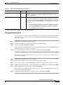
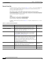
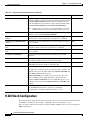
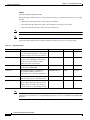
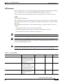
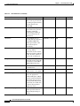
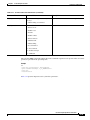
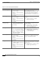
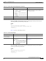
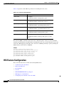
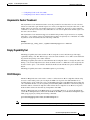
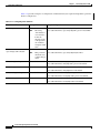
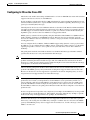
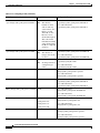
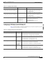
C H A P T E R
3
Provisioning the Cisco HSI
Introduction
This chapter describes the data that must be provisioned for the Cisco H.323 Signaling Interface (HSI).
The data is divided into two areas: system configuration and H.323 stack data. This chapter contains the
following sections:
•
Cisco HSI Configuration, page 3-1
•
H.323 Stack Configuration, page 3-10
•
HSI Feature Configuration, page 3-22
Cisco HSI Configuration
All configuration data is contained within configuration files. Cisco HSI starts with an initial
configuration file in $GWHOME/currentGW/etc/GWmain.conf. This file is created during installation
of the software.
The configuration data within the file is defined as dynamic, static, or constant:
•
Dynamic data can be modified by a provisioning session (see Appendix A, “MML User Interface
and Command Reference”). It can be activated on the currently running Cisco HSI.
•
Static data can be modified by a provisioning session but cannot be activated on a running
Cisco HSI. Changes to dynamic and static data can be written to a separate provisioning file (in
$GWHOME/currentGW/var/prov/configname/session.dat) that can be used during subsequent
restarts of the Cisco HSI.
•
Constant configuration data is contained within the configuration file and cannot be modified by
provisioning sessions. Constant configuration data can be modified only by system technicians or
administrators who use UNIX editing tools. This data is replicated from the initial configuration file
into the provisioning files, and is included in subsequent provisioning sessions.
Examples of the use of constant data are given in Appendixes D, E, F, and G. These appendixes
determine the mapping of cause values for incoming and outgoing H.323 and Enhanced ISDN User
Part (E-ISUP) messages. System technicians can modify these values in the initial configuration file
to explicitly choose the mappings for their system.
When a provisioning session creates a new configuration file, it also verifies that provisioned data is
within allowable ranges and indicates this in the start of the file. It checksums the configuration file and
writes the checksum as $GWHOME/currentGW/var/prov/configname/checksum.dat. When the Cisco
Cisco H.323 Signaling Interface User Guide
OL-4806-01 Rev. A14
3-1
Chapter 3
Provisioning the Cisco HSI
Cisco HSI Configuration
HSI starts up, it attempts to read the active configuration, checks that the configuration has been verified,
and ensures that the checksum matches. If the active configuration is not verified or if the checksum is
faulty, the configuration reverts to using the $GWHOME/currentGW/etc/GWmain.conf file.
All configuration data that can be set in the system is defined in the Skeleton Configuration file (see
Appendix B, “Skeleton Configuration File”). The Skeleton Configuration file defines the data names and
types (strings or numbers), and defines whether the data is dynamic, static, or constant.
MML Configuration Commands
There are three types of MML configuration command:
•
Configuration session commands that work with entire provisioning data files (see Table 3-1)
•
Configuration component or parameter commands that perform actions on components or
parameters affecting a specific data file (see Table 3-2)
•
Configuration export commands
For more information about MML configuration commands, see Appendix A, “MML User Interface and
Command Reference.”
Note
Parameter names used in MML commands are not case sensitive.
Table 3-1
Configuration Session Commands
Command
Description
prov-sta
Starts a provisioning session to create a new configuration or modify
an existing configuration
prov-cpy
Activates the configuration settings in the current provisioning
session
prov-stp
Terminates the provisioning session and saves the configuration
Table 3-2
Configuration Component or Parameter Commands
Command
Description
prov-add
Adds a component to the Cisco HSI
prov-dlt
Deletes a provisioned component
prov-ed
Modifies a provisioned component
prov-rtrv
Retrieves information about an existing provisioning session
The configuration export command is prov-exp, which exports the currently provisioned configuration
of the Cisco HSI to a file.
Cisco H.323 Signaling Interface User Guide
3-2
OL-4806-01 Rev. A14
Chapter 3
Provisioning the Cisco HSI
Cisco HSI Configuration
Introduction to MML Command Operation for HSI
After the HSI software is installed, you can configure additional items. The following MML command
examples show how to enable DTMF capability on the HSI. (For a description of the sys_config_static
entry and the dtmf parameters, please see the section (System Configuration Data).
Initiating an MML Session to Enable DTMF on the HSI
The following MML command example shows how to start an MML session and enable DTMF support
of the HSI:
Step 1
As root user, issue the following command:
/etc/init.d/CiscoGW start
Step 2
As mgcusr, begin an MML session by issuing the following command:
mml
Step 3
To enable DTMF support on the HSI, issue the following set of commands:
prov-sta:srcver=active, dstver=myconf
Note
The preceding command creates a new configuration, based on the current configuration, called
myconf.
prov-add:name=sys_config_static, dtmfsupportedtype=dtmf
prov-add:name=sys_config_static, dtmfsupporteddirection=both
prov-cpy
restart-softw
Note
Caution
Certain configuration changes do not take effect until the HSI is restarted. After the
restart-softw command is issued, the HSI restarts in approximately 20 seconds.
Use MML commands to perform all HSI configuration. Never manually edit system configuration files
because they do not undergo the same parse checks as MML commands. In addition, the HSI uses a
machine-generated checksum to verify the system files. If you modify the system configuration files
manually, the HSI cannot use them and reverts to the base configuration.
Verifying the Configuration
The following MML command examples show how to verify that configuration changes have been
correctly processed:
Step 1
To retrieve information about the current provisioning session, issue the following command:
prov-rtrv:list
Note
The HSI prints an asterisk next to the currently active configuration.
Cisco H.323 Signaling Interface User Guide
OL-4806-01 Rev. A14
3-3
Chapter 3
Provisioning the Cisco HSI
Cisco HSI Configuration
Step 2
To display the entire configuration, issue the following command:
rtrv-config
To display a subset of the configuration, one can issue a command such as the following:
rtrv-config:sys_config_static
Step 3
To exit the MML command interpreter, issue the following command:
quit
Reverting to the Base Configuration
The following MML command examples show how to revert to the base HSI configuration:
Step 1
To begin an MML session, issue the following command:
mml
Step 2
To revert to the base HSI configuration, issue the following command:
restart-softw:init
Note
The restart-softw:init command is derived from the initial installation script. (See Step 6 in the
“Installing Cisco HSI” section on page 2-5.) To return to the configuration “myconf,” one would issue
the command restart-softw:myconf.
System Configuration Data
System configuration data can be static or dynamic. Static data can be activated only at startup. Dynamic
data can be activated during system run time.
Static System Data
To modify the static system data parameters in Table 3-3, use the sys_config_static MML name variable
for the prov-add, prov-dlt, and prov-ed commands. Stop and restart the application for the changes to
take effect.
In the following example, the prov-add command adds the static system data parameter
VSCA_PORT_NUMBER1 to a static configuration file. The prov-ed command modifies the value of
the VSCA_PORT_NUMBER1 parameter. The prov-dlt command deletes the
VSCA_PORT_NUMBER1 parameter from the static configuration file.
Example
prov-add:name=sys_config_static,vsca_port_number1=8003
prov-ed:name=sys_config_static,vsca_port_number1=8002
prov-dlt:name=sys_config_static,vsca_port_number1
The parameters in Table 3-3 are written to a static configuration file or to a section within a file.
Cisco H.323 Signaling Interface User Guide
3-4
OL-4806-01 Rev. A14
Chapter 3
Provisioning the Cisco HSI
Cisco HSI Configuration
Table 3-3
Static System Data Parameters
Parameter
Type
Description
HOST_PORT_NUMBER1
[0-65535]
The first port number to be used by the Cisco HSI. The default value is 0.
Note
HOST_PORT_NUMBER2
[0-65535]
This value must match the peer port setting on the PGW1 2200
E-ISUP IPLNK object.
The second port number to be used by the Cisco HSI. The default value is 0.
Note
This value should always be set to 0.
VSCA_IPADDR1
STRING
The primary IP address of the primary PGW 2200.
VSCA_IPADDR2
STRING
The secondary IP address of the primary PGW 2200.
Note
VSCB_IPADDR1
STRING
The primary IP address of the secondary PGW 2200.
Note
VSCB_IPADDR2
STRING
This value must match that of VSCA_IPADDR1.
This parameter is not used in a standalone PGW configuration.
The secondary IP address of the secondary PGW 2200.
Note
The value of this parameter must match that of VSCB_IPADDR1.
This parameter is not used in a standalone PGW configuration.
VSCA_PORT_NUMBER1
[0-65535]
The first port number of the primary PGW 2200.
VSCA_PORT_NUMBER2
[0-65535]
The second port number of the primary PGW 2200.
Note
VSCB_PORT_NUMBER1
[0-65535]
The first port number of the secondary PGW 2200.
Note
VSCB_PORT_NUMBER2
[0-65535]
This value must match that of VSCA_PORT_NUMBER1.
This parameter is not used in a standalone PGW configuration.
The second port number of the secondary PGW 2200.
Note
The value of this parameter must match that of
VSCA_PORT_NUMBER2. This parameter is not used in a
standalone PGW configuration.
ClipClirSupported
STRING
CLI Presentation or restriction is enabled if this parameter is present and set to
anything other than “”. For example, to enable CLIP/CLIR support, set this
parameter explicitly to “Enabled.”
RaiSupported
STRING
RAI support is enabled if this parameter is present and set to anything other than
“”. For example, to enable RAI support, set this parameter to “Enabled.”
DtmfSupportedDirection
STRING
This is set to “both”, “tx,” or “rx”. If this parameter is not present or is set to any
value other than “both,” “tx,” or “rx,” the DTMF Relay feature is disabled.
DtmfSupportedType
STRING
This is set to “dtmf” or “basicString.” If this parameter is not present or set to
any other value, the DTMF Relay feature is disabled.
H225PavoSupported
STRING
Pavo support is enabled if this parameter is present and set to anything other than
“”. For example, set it to “Enabled.”
PavoRedirScreeningInd
[0-3]
The value of the Pavo redirecting number screening indicator. (If this parameter
is not provisioned, the default is Q.931 zero—user provided, not screened.)
PavoRedirReason
[0-15]
The value of the Pavo redirecting number reason field. This parameter has no
default. If unprovisioned, the redirecting number parameter will not contain the
Reason for Redirection field (octet 3b).
Cisco H.323 Signaling Interface User Guide
OL-4806-01 Rev. A14
3-5
Chapter 3
Provisioning the Cisco HSI
Cisco HSI Configuration
Table 3-3
Static System Data Parameters (continued)
Parameter
Type
Description
PavoRedirPresInd
[0-3]
The value of the Pavo redirecting number presentation indicator. (If this
parameter is not provisioned, the default is Q.931 zero—no indication.)
CliInDisplaySupported
STRING
T38MaxVal
STRING
If this parameter is present and set to anything other than “”, the Calling Number
is also sent in the DISPLAY IE. The NetMeeting endpoint retrieves the calling
party number from the DISPLAY IE in the H.225 setup message. To enable this
parameter, set it to “Enabled.”
The T38MaxVal parameter has the following optional attributes that can be
assigned values in a specific range.
Note
Values for the following attributes must be expressed in hexadecimal
format.
•
MaxBit—[0x0—0xFFFFFFFF]. Specifies the maximum bit rate in units
of 100 bits per second at which a transmitter can transmit or a receiver
can receive T.38 FAX data. The default value is 0x90.
•
FxMaxBuf—[0x0—0xFFFFFFFF]. Specifies the maximum buffer size
for the "t38FaxMaxBuffer" parameter for the T.38 over UDP option. The
default value is 0xc8.
FxMaxData—[0x0—0xFFFFFFFF]. Specifies the maximum datagram
size for the "t38FaxMaxDatagram" parameter for the T.38 over UDP
option. The default value is 0x48.
This T.38 Fax parameter is assigned one of the following optional values:
•
T38Options
STRING
•
FxFillBit—[0 or 1] The default value is 0.
•
FxTransMMR—[0 or 1] The default value is 0.
•
FxRateTransJBIG—[0 or 1] The default value is 0.
•
FXRate—[Local or Trans] The default value is Trans.
•
FxUdpEC—[Red or FEC] The default value is Red.
AsymmetricHandlingSupported
STRING
Asymmetric Codec Treatment support is enabled if this parameter is present and
set to anything other than “”. To enable Asymmetric Codec Treatment, set this
parameter to “Enabled.”
UseConfID
STRING
Use this parameter to specify the precedence of extracting the Global Call ID
from the Conference ID or the GUID in the H.225 Setup message. The
provisioning of this property to a value other than “” gives precedence to the
Conference ID. For example, set it to “Enabled.” To set the precedence to the
GUID field, the crafts person can either delete the property from the config or
set it to “”.
Cisco H.323 Signaling Interface User Guide
3-6
OL-4806-01 Rev. A14
Chapter 3
Provisioning the Cisco HSI
Cisco HSI Configuration
Table 3-3
Static System Data Parameters (continued)
Parameter
Type
Description
DualCLISupported
STRING
To enable Dual CLI support (see H.246 Annex C), set this parameter to anything
other than “”. For example, to explicitly enable Dual CLI support, set this
parameter to “Enabled.”
InjectPi8
STRING
If this parameter is set to a text value (for example, “enabled” or “true”), the HSI
inserts a progress indicator value of 8 into the H.225 alerting message, which
allows creation of a backward speech path. To disable this feature, you can delete
the parameter using the command prov-dlt or issue the prov-ed command and
set the value to ““.
Note
Setting the InjectPi8 parameter is required if the PSTN network does
not notify the HSI that inband information is available. For instance,
when no Optional Backward Call Indicator is present, a backward
speech path will not be available.
1. PGW = Public Switched Telephone Network (PSTN) Gateway
Changing Static System Data
To change static system data, you must first determine if it is acceptable to stop currently active calls in
20 seconds. If it is acceptable to stop active calls in 20 seconds, change static system data using the
following procedure:
Step 1
Modify the static parameters you want to change.
Step 2
Activate the changed static parameters by issuing the prov-cpy command.
Step 3
Issue the command restart-softw::confirm.
This command stops the HSI application in 20 seconds and then restarts it. The restarted HSI application
reads the changed static system data parameters.
Step 4
To ensure that traffic processing has resumed, issue the command rtrv-ne-health.
If you wish to change static system data but it is not acceptable to stop active calls in 20 seconds, use
the following procedure:
Step 1
Modify the static parameters you want to change.
Step 2
Activate the changed static parameters by issuing the prov-cpy command.
Step 3
Stop call processing by issuing the stp-callproc command, specifying the timeout period you require.
Step 4
When the timeout period expires, ensure that all traffic ceased by issuing the command rtrv-ne-health.
Step 5
Restart the HSI software by issuing the command restart-softw.
This command stops the HSI application and then restarts it. The restarted HSI application reads the
changed static system data parameters.
Step 6
To ensure that traffic processing has resumed, issue the command rtrv-ne-health.
Cisco H.323 Signaling Interface User Guide
OL-4806-01 Rev. A14
3-7
Chapter 3
Provisioning the Cisco HSI
Cisco HSI Configuration
Dynamic System Data
To modify the dynamic system data parameters in Table 3-4, use the sys_config_dynamic MML name
variable for the prov-add, prov-dlt, and prov-ed commands. You need not halt and restart call
processing for the changes to take effect.
In the following example, the prov-add command adds the dynamic system data parameter
OVLDLEVEL1PERCENT to a dynamic configuration file. The prov-ed command modifies the value of
the OVLDLEVEL1PERCENT parameter. The prov-dlt command deletes the OVLDLEVEL1PERCENT
parameter from the dynamic configuration file.
Example
prov-add:name=sys_config_dynamic,OVLDLEVEL1PERCENT=20
prov-ed:name=sys_config_dynamic,OVLDLEVEL1PERCENT=25
prov-dlt:name=sys_config_dynamic,OVLDLEVEL1PERCENT
The MML commands write the parameters in Table 3-4 to a dynamic configuration file or to a section
within a file.
Table 3-4
Dynamic System Data Parameters
Parameter
Description
Default
LOGDIRECTORY
Specifies the directory used when the active log file is created, and
also specifies the directory where the rotated log file is stored.
/var/log/
LOGFILENAMEPREFIX
Specifies the filename prefix used when the log files are created or
rotated. The .log postfix is appended to the end of the prefix to
establish the name of the active log file.
platform.log
LOGPRIO
Defines the initial logging levels. By default it is set to TRACE. When TRACE
the system initializes and is running, the levels set for individual
packages (0x0000 to 0xFFFF) determine the log levels. See the
“Logging Levels” section on page 4-10.
LOGFILEROTATESIZE
10 Mb
Triggers a log file rotation based on the size of the active file. The
application regularly checks the current size of the file to determine
whether a rotation is required. If a file rotation is triggered by this
parameter, the rotated file might be slightly larger than the size
specified by this parameter. This parameter triggers a file rotation and
also resets the timer associated with the
LOGFILEROTATEINTERVAL parameter.
LOGFILEROTATEINTERVAL
Triggers a log file rotation based on the time elapsed since the
previous rotation. This timer is reset after any rotation occurs,
regardless of the cause or trigger of the rotation.
1440 minutes
(24 hours)
IPADDRNMS
Defines the IP address of the network management system.
—
OVLDSAMPLERATE
Defines the frequency of CPU sampling and threshold checking.
3000 millisecond
(ms) polling rate
Cisco H.323 Signaling Interface User Guide
3-8
OL-4806-01 Rev. A14
Chapter 3
Provisioning the Cisco HSI
Cisco HSI Configuration
Table 3-4
Dynamic System Data Parameters (continued)
Parameter
Description
OVLDLEVEL1PERCENT
20
Indicates what percentage of calls should be rejected when an
overload condition occurs. This parameter is used in conjunction with
the OVLDLEVEL1FILTER parameter. The overload level 1 value is
the lowest level of overload and must be less than or equal to the
provisioned values for OVLDLEVEL2PERCENT and
OVLDLEVEL3PERCENT.
Note
OVLDLEVEL1FILTER
Default
If this value is set to zero, no overload level 1 treatment
occurs.
Indicates what call types should be gapped if an overload level 1
condition occurs. The possible values are:
•
Normal—Emergency or priority calls are not gapped.
•
All—All calls are gapped, regardless of type.
Note
Normal
If the overload percentage is set to 100, all calls are gapped
irrespective of this setting.
OVLDLEVEL1THRESHLOWER Determines the number of active calls below which the application
CALLS
load must fall in order to remove the overload level 1 condition.
1800
OVLDLEVEL1THRESHUPPER
CALLS
1900
Determines how many simultaneous active calls trigger an overload
level 1 condition.
OVLDLEVEL1THRESHLOWER Determines the CPU utilization level below which the application
CPU
must fall in order to remove the overload level 1 condition.
60
OVLDLEVEL1THRESHUPPER
CPU
Determines the level of CPU utilization that triggers an overload
level 1 condition.
65
OVLDLEVEL2PERCENT
Indicates what percentage of calls should be rejected when an
75
overload condition occurs. The parameter is used in conjunction with
the OVLDLEVEL2FILTER parameter. This is the second level of
overload and must be less than or equal to the provisioned value of
OVLDLEVEL3PERCENT and greater than or equal to the
provisioned value of OVLDLEVEL1PERCENT.
Note
OVLDLEVEL2FILTER
If this value is set to zero, no overload level 1 or 2 treatment
occurs (by definition, the level 1 value must also be zero).
Indicates what call types should be gapped if an overload level 2
condition occurs (see OVLDLEVEL1FILTER).
Normal
OVLDLEVEL2THRESHLOWER Determines the number of active calls below which the application
CALLS
load must fall in order for the overload level 2 condition to be
removed.
2000
OVLDLEVEL2THRESHUPPER
CALLS
2200
Determines how many simultaneous active calls trigger an overload
level 2 condition.
OVLDLEVEL2THRESHLOWER Determines the level of CPU utilization below which the application 70
CPU
must fall in order for the overload level 2 condition to be removed.
OVLDLEVEL2THRESHUPPER
CPU
Determines the level of CPU utilization that triggers an overload
level 2 condition.
80
Cisco H.323 Signaling Interface User Guide
OL-4806-01 Rev. A14
3-9
Chapter 3
Provisioning the Cisco HSI
H.323 Stack Configuration
Table 3-4
Dynamic System Data Parameters (continued)
Parameter
Description
OVLDLEVEL3PERCENT
Indicates what percentage of calls should be rejected when an
90
overload condition occurs. The parameter is used in conjunction with
the OVLDLEVEL3FILTER parameter. This is the highest level of
overload and must be greater than or equal to the provisioned values
for OVLDLEVEL1PERCENT and OVLDLEVEL2PERCENT.
Note
OVLDLEVEL3FILTER
Default
If this value is set to zero, no overload treatment occurs (by
definition, the level 1 and level 2 values must also be zero).
Indicates what call types should be gapped if an overload level 3
condition occurs (see OVLDLEVEL1FILTER).
Normal
OVLDLEVEL3THRESHLOWER Determines the number of active calls below which the application
CALLS
load must fall in order to remove the overload level 3 condition.
2300
OVLDLEVEL3THRESHUPPER
CALLS
2400
Determines how many simultaneous active calls trigger an overload
level 3 condition.
OVLDLEVEL3THRESHLOWER Determines the level of CPU utilization below which the application 85
CPU
must fall in order to remove the overload level 3 condition.
OVLDLEVEL3THRESHUPPER
CPU
Determines the level of CPU utilization that triggers an overload
level 3 condition.
95
CIAGENTSCANPERIOD
Specifies the frequency with which the CIagent polls the CPU
utilization.
—
ALARMDEBOUNCETIME
Specifies the length of time that an alarm condition must persist
before being reported, and any associated action taken.
0
CALLREFERENCEUSAGE
Determines which call reference identity is passed on to the
PGW 2200 (call reference field or Conference ID).
—
DISKUSAGELIMIT
Represents a percentage of disk occupancy.
95
The application continually polls the system for disk occupancy, and
if the percentage rises above the limit set by DISKUSAGELIMIT, the
LOW_DISK_SPACE alarm is raised.
DISKUSAGELIMIT has a default value of 95 percent. The value
range is 0–100, inclusive. When dynamically provisioned, the
parameter DISKUSAGELIMIT, if not set within that range, is set to
the default value (95) and the CONFIGURATION_ FAILURE alarm
is raised.
RegFailureReleaseCause
This parameter specifies the Q.850 release cause, which the HSI uses —
after the HSI fails three times to register to a gatekeeper.
This parameter is assigned a value in the range 1—127
H.323 Stack Configuration
The parameter name is based on the ASN.1 paths; but, in some cases, the parameter name has been
shortened for convenience. For example, “capabilities” has been shortened to “caps.”
The case of the parameter name reflects exactly the ASN.1 definitions; but, case is not important to
MML configuration.
Cisco H.323 Signaling Interface User Guide
3-10
OL-4806-01 Rev. A14
Chapter 3
Provisioning the Cisco HSI
H.323 Stack Configuration
Nonprovisionable Data
The parameters in Table 3-5 cannot be altered through MML commands.
Table 3-5
Nonprovisionable Data Parameters
H323_SYS
Description
system.manualstart
Present
system.pdlname
Absent
system.delimiter
#FF
ras.gatekeeper
Absent
ras.rasmulticastaddress
224.0.1.41.1718
h245.capabilities.manualoperation
Present
h245.masterslave.manualoperation
Present
q931.manualaccept
Present
q931.earlyH245
Present
q931.autoanswer
Present
q931.manualcallprocessing
Present
q931.h245tunneling
Present
MML Provisionable Data
H.323 System Parameters
The parameters in Table 3-6 are required for H.323 stack initialization. To modify the parameters in
Table 3-6, use the h323_sys MML name variable for the prov-add, prov-dlt, and prov-ed commands.
Stop and restart the application for these changes to take effect.
Note
Table 3-6
The asterisk (*) after a parameter name in the first column of Table 3-6 denotes a mandatory RADVision
parameter that has an inbuilt default value if a value is not set in provisioning.
H.323 System Initialization Parameters
Parameter
Description
Type
Example
maxCalls*
Maximum number of concurrent calls allowed
INTEGER(0, 65535)
2500
maxChannels*
Maximum number of concurrent channels allowed
INTEGER(0, 65535)
2
Q.931 Parameters
To modify the parameters listed in Table 3-7, use the q931 MML name variable for the prov-add,
prov-dlt, and prov-ed commands.
In the following example, the prov-add command sets the Q.931 parameter maxCalls to the value 2000.
Cisco H.323 Signaling Interface User Guide
OL-4806-01 Rev. A14
3-11
Chapter 3
Provisioning the Cisco HSI
H.323 Stack Configuration
Example
prov-add:name=q931,maxCalls=2000
The Update Type column in Table 3-7 shows when the change to a parameter takes effect once a change
is made:
Table 3-7
•
Immediate means that the effect of the change is immediate.
•
Start means that the application needs to be restarted for the change to take effect.
•
Next Call means that the next call has the new parameter set.
Note
Immediate and Next Call update types refer to dynamic system data.
Note
The asterisk (*) after a parameter name in the first column of Table 3-7 denotes a mandatory RADVision
parameter with an inbuilt default value that will be used if the value is not set in provisioning.
Q.931 Parameters
Parameter Name
Description
Example
Update Type
responseTimeOut*
The maximum time (in seconds) permitted INTEGER(1,200)
to receive the first response to a call. If this
parameter expires, the call is disconnected.
20
Immediate
connectTimeOut*
The maximum time (in seconds) the stack
waits for call establishment after the first
response is received. If this parameter
expires, the call is disconnected.
INTEGER(1,20000)
180
Immediate
callSignalingPort*
The number of the port receiving the calls
destined for the PGW 2200.
INTEGER(0,65535)
1720
Start
maxCalls*
The maximum number of simultaneous
INTEGER(0,65535)
calls permitted. If this parameter is
exceeded, the next call attempt returns busy.
2500
Next Call
notEstablishControl
The stack does not allow the switching of
control from the Q.931 to the H.245 stack.
Not present
Next Call
overlappedSending
NULL
Because the Q.931 configuration flag
indicates that both parties support overlap
sending, this state notifies the other party
that it can send an overlap sending message.
Present
Immediate
Note
Type
NULL
The Q.931 parameter overlappedSending has been combined with the RAS overlappedSending
parameter. If you set the Q.931 overlappedSending parameter, you also set the RAS overlappedSending
parameter.
Cisco H.323 Signaling Interface User Guide
3-12
OL-4806-01 Rev. A14
Chapter 3
Provisioning the Cisco HSI
H.323 Stack Configuration
RAS Parameters
The parameters in Table 3-8 are required for RAS stack initialization. To modify the RAS parameters,
use the ras MML name variable for the prov-add, prov-dlt, and prov-ed commands.
In the following example, the prov-add command sets the RAS parameter maxfail to the value 3.
Example
prov-add:name=ras,maxfail=3
The array index [i] in some of the parameter names in the first column of Table 3-8 must be replaced
with a valid braced index from 1 to 20, and must be continuous and unique (that is, it must contain no
duplicates).
The Update Type column in Table 3-8 shows when the change to a parameter takes effect after it is
modified:
Table 3-8
•
Immediate means that the effect of the change is immediate.
•
Start means that the application needs to be restarted for the change to take effect.
•
Next Call means that the next call has the new parameter set.
Note
Immediate and next call update types are dynamic system data.
Note
The RAS parameter overlappedSending is not available here because it has been combined with the
Q.931 overlappedSending parameter. If you set the Q.931 overlappedSending parameter, you also set the
the RAS overlappedSending parameter.
Note
The asterisk (*) after a parameter name in the first column of Table 3-8 denotes a mandatory RADVision
parameter with an inbuilt default value that will be used if the value is not set in provisioning.
RAS Parameters
Parameter Name
Description
Type
Example
Update Type
manualRAS
If this parameter is present,
the stack does not perform
automatic RAS procedures
(it waits to be driven by the
application).
NULL
—
Start
responseTimeOut*
INTEGER(1, 200)
The time (in seconds) that
the stack waits until it
notifies the application that
the called party has failed to
respond to a transaction.
10
Immediate
maxFail*
Maximum number of retry
gatekeeper registration
attempts.
3
Immediate
INTEGER(1, 200)
Cisco H.323 Signaling Interface User Guide
OL-4806-01 Rev. A14
3-13
Chapter 3
Provisioning the Cisco HSI
H.323 Stack Configuration
Table 3-8
RAS Parameters (continued)
Parameter Name
Description
Type
Example
Update Type
allowCallsWhenNonReg
If this parameter is present, it NULL
allows calls to proceed even
if gatekeeper registration has
not been done for the
PGW 2200.
Not present
Immediate
manualRegistration
If this parameter is present,
the stack does not perform
automatic gatekeeper
registration procedures (it
waits to be driven by the
application).
NULL
Not present
Stop/Start
timeToLive
INTEGER(1, 65535)
The maximum time (in
seconds) that the registration
of the PGW 2200 with a
gatekeeper remains valid.
The stack reregisters
periodically.
400
Immediate
rasPort*
The number of the port
receiving all RAS
transactions for the current
endpoint. Set this parameter
to 0 to allow the software to
look for the available port.
0
Start
compare15bitRasCrv
If this parameter is present, it NULL
causes the stack to ignore the
call reference value (CRV)
MSBit in RAS messages.
—
Immediate
maxRetries*
Maximum number of RAS
retransmissions.
INTEGER(1, 200)
3
Immediate
maxMulticastTTL
Maximum number of
INTEGER(0, 200)
multicast time to live (TTL).
3
Start
preGrantedArqUse
Choice of direct or routed. If STRING
direct, the pregranted
Admission Request (ARQ)
feature is used for both direct
and routed calls. If routed,
the pregranted ARQ feature
is used only for routed calls.
If absent, the pregranted
ARQ is not used.
direct
Next Call
manualDiscovery.ipAddress
The IP address of a known
gatekeeper with which an
endpoint might attempt to
register.
10.70.54.53
Start
INTEGER(0, 65535)
STRING
Cisco H.323 Signaling Interface User Guide
3-14
OL-4806-01 Rev. A14
Chapter 3
Provisioning the Cisco HSI
H.323 Stack Configuration
Table 3-8
RAS Parameters (continued)
Parameter Name
Description
manualDiscovery.port
Example
Update Type
The port associated with the INTEGER(0, 65535)
manualDiscovery.ipAddress,
which can, by agreement, be
either a well-known port or
another port.
1719
Start
gateway.prefix[i]
STRING
The gateway registers the
telephone prefix specified by
this parameter to indicate
that it is able to terminate it.
0208
Immediate
gatekeeperId
Identifies the gatekeeper
with which the endpoint is
trying to register.
OuterLondon
Immediate
terminalAlias[i].e164
STRING
Two variants of the same
address for the endpoint;
STRING
e164 is numeric and h323ID
is text.
0208001000
Immediate
terminalAlias[i].h323ID
endpointVendor.t35CountryCode
Type
STRING
[email protected] Immediate
These parameters identify
the manufacturer of the
endpoint.
INTEGER(0, 255)
11
Immediate
INTEGER(0, 255)
11
Immediate
INTEGER(0, 65535)
9
Immediate
endpointVendor.productId
Data that the manufacturer
assigns to each product.
STRING
H323ESP
Immediate
endpointVendor.versionId
Data that the manufacturer
assigns to each version.
STRING
R0.2.4
Immediate
endpointVendor.t35Extension
endpointVendor.manufacturerCode
H.245 Parameters
To modify the H.245 parameters listed in Table 3-9, use the h245 MML name variable for the prov-add,
prov-dlt and prov-ed commands.
In the following example, the prov-add command sets the H.245 parameter masterSlave.timeout to the
value 5.
Example
prov-add:name=h245,masterSlave.timeout=5
The Update Type column in Table 3-9 shows when a change to an H.245 parameter takes effect after it
is modified:
Note
•
Immediate means that the effect of the change is immediate.
•
Start means that the application needs to be restarted for the change to take effect.
•
Next Call means that the next call has the new parameter set.
Immediate and Next Call update types are dynamic system data.
Cisco H.323 Signaling Interface User Guide
OL-4806-01 Rev. A14
3-15
Chapter 3
Provisioning the Cisco HSI
H.323 Stack Configuration
Table 3-9
H.245 Parameters
Parameter Name
Description
Type
Example
Update
Type
masterSlave.terminalType
The terminal type for the
PGW 2200.
INTEGER(0, 255)
60
Next Call
masterSlave.manualResponse
NULL
If this parameter is present, it
cancels automatic
acknowledgment of master or slave
determination.
Present
Next Call
masterSlave.timeout
The maximum time (in seconds)
INTEGER(0, 65535) 5
the stack waits before it gives up on
the master/slave procedure.
Immediate
channelsTimeout
The time (in seconds) the stack
waits for a response to a channel
establishment message.
INTEGER(0, 65535) 10
Immediate
roundTripTimeout
The time (in seconds) the stack
waits for round-trip procedure
completion.
INTEGER(0, 65535) 5
Immediate
requestCloseTimeout
The time (in seconds) the stack
waits for request close procedure
completion.
INTEGER(0, 65535) 5
Immediate
requestModeTimeout
The time (in seconds) the stack
waits for request mode procedure
completion.
INTEGER(0, 65535) 5
Immediate
caps.timeout
The maximum time (in seconds)
INTEGER(0, 65535) 5
the stack waits before it gives up on
the capability exchange procedure.
Immediate
caps.maxAudioDelay
Maximum H.255 multiplex audio
delay jitter.
INTEGER(0, 1023)
Immediate
mediaLoopTimeout
The timeout (in seconds) of the
media loop procedure.
INTEGER(0, 65535) 5
60
Immediate
Table 3-10, Table 3-11, and Table 3-12 list the parameters and modes related to the configuring of
codecs. The array index [i] must be replaced with a valid braced index from 1 to 20. The braced index
must be continuous and unique (that is, there must be no duplicates).
Table 3-10
H.245 Terminal Capability Codec Parameters
Parameter Name
Type
caps.table[i].entryNo
INTEGER(1, 65535)
caps.table[i].audio.g711Alaw64k
INTEGER(1, 256)
caps.table[i].audio.g711Alaw56k
INTEGER(1, 256)
caps.table[i].audio.g711Ulaw64k
INTEGER(1, 256)
caps.table[i].audio.g711Ulaw56k
INTEGER(1, 256)
caps.table[i].audio.g722at64k
INTEGER(1, 256)
Cisco H.323 Signaling Interface User Guide
3-16
OL-4806-01 Rev. A14
Chapter 3
Provisioning the Cisco HSI
H.323 Stack Configuration
Table 3-10
H.245 Terminal Capability Codec Parameters (continued)
Parameter Name
Type
caps.table[i].audio.g722at56k
INTEGER(1, 256)
caps.table[i].audio.g722at48k
INTEGER(1, 256)
caps.table[i].audio.g7231.maxAudioFrames
INTEGER(1,256)
caps.table[i].audio.g7231.silenceSuppression
INTEGER(0,1)
caps.table[i].audio.g728
INTEGER(1, 256)
caps.table[i].audio.g729
INTEGER(1, 256)
Table 3-11 H.245 Channel Codec Parameters
Parameter Name
Type
chan[i].name
STRING
chan[i].audio.g711Alaw64k
INTEGER(1, 256)
chan[i].audio.g711Alaw56k
INTEGER(1, 256)
chan[i].audio.g711Ulaw64k
INTEGER(1, 256)
chan[i].audio.g711Ulaw56k
INTEGER(1, 256)
chan[i].audio.g722at64k
INTEGER(1, 256)
chan[i].audio.g722at56k
INTEGER(1, 256)
chan[i].audio.g722at48k
INTEGER(1, 256)
chan[i].audio.g7231.maxAudioFrames
INTEGER(1,256)
chan[i].audio.g7231.silenceSuppression
INTEGER(0,1)
chan[i].audio.g728
INTEGER(1, 256)
chan[i].audio.g729
INTEGER(1, 256)
Table 3-12 H.245 Modes
Parameter Name
Type
modes[i].name
STRING
modes[i].audio.g711Alaw64k
NULL
modes[i].audio.g711Alaw56k
NULL
modes[i].audio.g711Ulaw64k
NULL
modes[i].audio.g711Ulaw56k
NULL
modes[i].audio.g722at64k
NULL
modes[i].audio.g722at56k
NULL
modes[i].audio.g722at48k
NULL
modes[i].audio.g7231
INTEGER(1,256)
modes[i].audio.g728
NULL
modes[i].audio.g729
NULL
Cisco H.323 Signaling Interface User Guide
OL-4806-01 Rev. A14
3-17
Chapter 3
Provisioning the Cisco HSI
H.323 Stack Configuration
Codec Selection
The Cisco HSI negotiates the media stream codec to establish a match between the PSTN MGCP media
gateway (for example, the Cisco AS5xxx series or Cisco MGX series) and the H.323 endpoint or
gateway. To match codecs, the MGCP gateway must be configured to match what is expected at the
H.323 end. Similarly, the Cisco HSI also must be configured with the same codecs.
The Cisco HSI receives a list of codecs from the MGCP gateway and matches the listed codecs to the
codecs that are configured on the HSI. The HSI advertises all of the successful matches in the H.245
terminalCapabilitySet messaging with the H.323 endpoint.
It is important to determine and configure the “frames-per-packet” value correctly on the Cisco HSI per
codec. If “frames-per-packet” value is incorrect, the codec may not be negotiated successfully between
the HSI and the H.323 endpoint.
It is also important to configure the MGCP gateway correctly. The gateway should be configured to
provide “static payload” values for the required codecs, rather than dynamic payload types (see Table 4
in RFC 3551, Schulzrinne and Casner).
Quick Reference for Important Parameters
Table 3-13, Table 3-14, Table 3-15, and Table 3-16 can be used in initial HSI configuration. The tables
present parameters that you might use frequently to align the Cisco HSI with an existing PSTN or Voice
over IP network.
Table 3-13 presents important call control parameters.
Table 3-13 Common Call Control Parameters
Parameter Name
Parameter Value
Description
A_CC_oLinecall
0—Unknown
Calling party's category
10—Ordinary
A_CC_Clir
0—No indication
Address presentation restricted indicator
1—Presentation allowed
2—Presentation restricted
3—Address not available
A_CC_ANumDataSI
0—None
Screening indicator
1—User provided not verified
2—User provided verified passed
3—User provided verified failed
4—Network provided
A_CC_oIsdnAllTheWay
0—ISDN user part not used all the way
Forward call indicator, ISUP indicator
1—ISDN user part used all the way
A_CC_oIsdnPref
0—ISDN user part preferred all the way
Forward call indicator, ISUP preference
1—ISDN user part not required all the
way
2—ISDN user part required all the way
Cisco H.323 Signaling Interface User Guide
3-18
OL-4806-01 Rev. A14
Chapter 3
Provisioning the Cisco HSI
H.323 Stack Configuration
Table 3-13 Common Call Control Parameters (continued)
Parameter Name
Parameter Value
Description
A_CC_Interworking
0—No interworking encountered (SS7 all Backward call indicator, Interworking indicator
the way)
1—Interworking encountered
A_CC_Location
1—User
Cause indicator, Location
2—Private local
3—Public local
4—Transit
5—Public remote
6—Private remote
7—International
8—Interworking
9—Local interface
11—Local remote
12—Packet manager
13—Unknown
The following MML command example shows the command sequence used to provision the call control
parameters provided in the preceding table.
Example
mml
> prov-sta::srcver=active, dstver=myconf
> prov-ed:name=CCPackage, A_CC_ANumDataSI=2
> prov-cpy
> restart-softw
Table 3-14 presents important static system data parameters.
Cisco H.323 Signaling Interface User Guide
OL-4806-01 Rev. A14
3-19
Chapter 3
Provisioning the Cisco HSI
H.323 Stack Configuration
Table 3-14 Common Static System Data Parameters
Parameter Name
Parameter Values
Description
CarrierCodeMapping
•
ClipClirSupported
•
“enabled”—a string that indicates the Allows transit of CLI presentation/screening
feature is enabled.
information.
•
Blank (“”)—indicates the feature is
disabled
•
“deleted”—indicates that the feature
is disabled
•
“dtmf”—the recommended value for Selects the DTMF type during H.245 terminal
interworking with Cisco gateways
capabilities exchange.
•
“basicString”
Note
•
“tx”—transmit to H323 endpoint
Selects DTMF transit direction.
•
“rx”—receive from H.323 endpoint
Note
•
“both”—transmit and receive DTMF
•
Blank (“”), “deleted,” or any other
string, such as “disabled”—indicates
the feature is disabled
DtmfSupportedType
DtmfSupportedDirection
H225PavoSupported
“enabled”—a string that indicates the Allows the mapping of a special tech prefix (the
format of which is CCxCy) to the
feature is enabled.
DestinationCircuitID “group” field in the ARQ
• Blank (“”)—indicates the feature is
message. This feature works only with IOS
disabled.
Gatekeeper build Release 12.2(15)T10 or above.
• “deleted”—indicates that the feature
is disabled.
Setting this parameter to “enabled”
enables use of Caller ID.
Set this parameter to “dtmf” and the
DtmfSupportedDirection parameter to
“both” to enable DTMF support.
Set this parameter to “both” and the
DtmfSupportedType parameter to “dtmf”
to enable DTMF support.
“enabled”—a string that indicates the Allows transit of redirecting number parameter
(contained in Cisco CallManager H.225 setup
feature is enabled.
messages—nonStandardControl field).
• Blank (“”)—indicates the feature is
disabled
•
•
RaiSupported
Note
“deleted”—indicates that the feature
is disabled
For example:
Allows H.225 RAS RAI messages to be sent to the
gatekeeper if the E-ISUP link fails or if the HSI is
• “enabled”—a string that indicates the
under heavy load.
feature is enabled.
Note
Set this parameter to “enabled” to enable
• Blank (“”)—indicates the feature is
the HSI to support RAI messages.
disabled
•
“deleted”—indicates that the feature
is disabled
Cisco H.323 Signaling Interface User Guide
3-20
OL-4806-01 Rev. A14
Chapter 3
Provisioning the Cisco HSI
H.323 Stack Configuration
Table 3-14 Common Static System Data Parameters (continued)
Parameter Name
Parameter Values
NotifyMsgEnabled
For example:
Description
Allows transit of connected number, display
information, and generic notification indicator in
• “enabled”—a string that indicates the
H.225 Notify messages.
feature is enabled.
VSCB_IPADDR1/2
•
Blank (“”)—indicates the feature is
disabled
•
“deleted”—indicates that the feature
is disabled
IP address, for example: “10.10.10.1”
VSCB_PORT_NUMBER1/2 Port number, for example: 8003
Allows IP address configuration of second PGW.
Allows port configuration of second PGW.
The following MML command example shows the command sequence used to provision the static
system data parameters provided in the preceding table.
Example
mml
> prov-sta::srcver=active, dstver=myconf
> prov-ed:name=SYS_CONFIG_STATIC, DtmfSupportedType=”dtmf”
> prov-cpy
> restart-softw
Table 3-15 presents common RAS parameters.
Table 3-15 Common RAS Parameters
Parameter Name
Parameter Value
Description
gateway.prefix[1]
For example: 020
HSI prefix (for gatekeeper registration)
Integer (to specify number of seconds)
for example, 45
RAS registration time to live.
gateway.prefix[2]
timeToLive
Note
See Table 3-8.
To enable lightweight RRQs, the
value for this parameter should be
set substantially lower than the
default (600).
The following MML command example shows the command sequence used to provision the RAS
parameters provided in the preceding table.
Example
mml
> prov-sta::srcver=active, dstver=myconf
> prov-ed:name=RAS, timeToLive=45
> prov-cpy
> restart-softw
Cisco H.323 Signaling Interface User Guide
OL-4806-01 Rev. A14
3-21
Chapter 3
Provisioning the Cisco HSI
HSI Feature Configuration
Table 3-16 presents common H.245 parameters for enabling the G.729 codec.
Table 3-16 Common H.245 Parameters
Parameter Name
Parameter Value
chan[i].name
For example:
prov-add:name=”H245”,chan[4].name=”g729”
chan[i].audio.g729
For example:
prov-add:name=”H245”,chan[4].audio.g729=”2”
caps.table[i].audio.g729
For example:
prov-add:name=”H245”,caps.table[4].audio.g729=”2”
caps.table[i].entryNo
For example:
prov-add:name=”H245”,caps.table[4].entryno=”729”
modes[i].name
For example:
prov-add:name=”H245”,modes[3].name=”g729”
modes[i].audio.g729
For example:
prov-add:name=”H245”,modes[3].audio.g729=”3].audio.
g729=””
The following MML command example shows the command sequence used to provision the H.245
parameters provided in the preceding table for enabling the G.729 codec. Provisioning the G.729 codec
on the Cisco HSI supports passing SS7 calls to the Cisco CallManager through a gateway running the
Media Gateway Control Protocol (MGCP).
Example
prov-sta::srcver=”active”,dstver=”g729"
prov-add:name=”H245”,caps.table[4].audio.g729=”2”
prov-add:name=”H245”,caps.table[4].entryno=”729”
prov-add:name=”H245”,chan[4].audio.g729=”2”
prov-add:name=”H245”,chan[4].name=”g729”
prov-add:name="H245",modes[3].audio.g729=""
prov-add:name=”H245”,modes[3].name=”g729”
HSI Feature Configuration
This section describes how to enable the following HSI features:
•
Asymmetric Codec Treatment
•
Empty Capability Set
•
H.323 Hairpin
•
T.38 Fax
•
HSI INFORMATION Message Support
•
HSI Support for Tech Prefixes
•
Configuring Clear Channel on the Cisco HSI
Cisco H.323 Signaling Interface User Guide
3-22
OL-4806-01 Rev. A14
Chapter 3
Provisioning the Cisco HSI
HSI Feature Configuration
•
Configuring G.726 on the Cisco HSI
•
Configuring G.729 Annex and G.729 Annex B
Asymmetric Codec Treatment
The Asymmetric Codec Treatment feature averts the potential for inconsistencies in codec selection,
which can result if the open channel requests are sent by each endpoint at nearly the same time, so that
neither side has received an open channel request prior to sending one. In practice, such asymmetric
conditions occur only for slow start calls. When there is a fast start recipient, both channels agree to use
the same codec in unison.
The Asymmetric Codec Treatment support is enabled if this parameter is present and set to anything
other than “”. For example, support is enabled if the parameter is explicitly set to “Enabled.” To enable
Asymmetric Codec Treatment, enter the following command:
Example:
prov-add:name=sys_config_static, asymmetrichandlingsupported = "Enabled"
Empty Capability Set
The Empty Capability Set feature enables an H.323 endpoint to send a TCS message with empty
capabilities during a call. The TCS message causes the audio channels to close. This action enables the
negotiation and opening of new audio channels.
The Empty Capability Set feature is useful when the H.323 endpoint wishes to change the audio codec
during a call or if the endpoint needs to divert the media streams to a different location. Typically, the
feature is used to place a call on hold to disable the media stream until the user presses the Resume
button.
The Empty Capability Set feature on the HSI requires no provisioning.
H.323 Hairpin
The H.323 Hairpin feature can be used to connect a call between two H.323 endpoints without using
resources on the media gateway. For example, the PGW can respond to the dialled number in an
incoming H.323 call by routing the call to another HSI (perhaps the same HSI) rather than routing the
call to the PSTN. In this case, the originating and terminating HSIs establish the call normally but pass
the H.245 address of the H.323 endpoints. This enables the two endpoints to use H.245 to negotiate
media channels with each other directly, independent of the HSI.
The H.323 Hairpin feature on the HSI requires no provisioning. However, to operate throughout the
system, H.323 Hairpin must be enabled on the PGW. On the PGW, you enable H.323 Hairpin through a
trunk group property by issuing the following commands:
prov-add:trnkgrpprop:name="2000",AllowH323Hairpin="1"
prov-add:trnkgrpprop:name="3000",AllowH323Hairpin="1"
Note
H.323 Hairpin must be enabled for both the ingress and egress EISUP trunk groups.
Cisco H.323 Signaling Interface User Guide
OL-4806-01 Rev. A14
3-23
Chapter 3
Provisioning the Cisco HSI
HSI Feature Configuration
Refer to Cisco PGW and Cisco IOS documentation at www.cisco.com for further information on these
commands.
T.38 Fax
The T.38 Fax feature enables the HSI to alter a call, initially established for voice, to support a fax
transmission.
When a fax call is initiated, a voice call is established. When the terminating gateway detects the fax
tone generated by the terminating fax machine, the gateway initiates a T.38 mode request using H.245
procedures from the terminating gateway. If the opposite end of the call acknowledges the T.38 mode
request, the initial audio channel is closed and a T.38 fax relay channel is opened.
You enable T.38 Fax for the HSI by specifying static system data parameters. By default, T.38 is
provisioned on the HSI by use of the following commands:
prov-add:name=sys_config_static,t38maxval="MaxBit 0x90, FxMaxBuf 0xc8, FxMaxData 0x48"
prov-add:name=sys_config_static,t38options="FxFillBit 0, FxTransMMR 0, FxTransJBIG 0,
FxRate Trans, FxUdpEC Red"
Table 3-3 describes the T.38 static system data parameters. The T.38 parameters for HSI correspond to
T.38 parameters proposed in the ITU T.38 recommendation.
Configuring T.38 Fax on the Cisco PSTN Gateway
To enable T.38 Fax throughout the system, you must enable T.38 Fax on the Cisco PGW. On the PGW,
T.38 is enabled through a trunk group property by use of the following MML command:
prov-add:trnkgrpprop:name="2000",FaxSupport="1"
Configuring T.38 Fax on a Cisco IOS H.323 Gateway
Enable T.38 Fax on a Cisco IOS H.323 gateway by issuing the following IOS commands:
voice service voip
fax protocol t38 ls-redundancy 0 hs-redundancy 0 fallback none
Configuring T.38 Fax on a Cisco IOS MGCP Gateway
Enable T.38 fax on a Cisco IOS MGCP gateway by issuing the following IOS commands:
voice service voip
fax protocol t38 ls-redundancy 0 hs-redundancy 0 fallback none
mgcp package-capability fxr-package
Refer to PGW and Cisco IOS documentation at www.cisco.com for further information on these
commands.
HSI INFORMATION Message Support
Cisco CallManager uses the H.225 INFORMATION message during transfer to indicate that ringback
tone is on or off. The Cisco HSI now supports this message to correctly interoperate with Cisco
CallManager.
Cisco H.323 Signaling Interface User Guide
3-24
OL-4806-01 Rev. A14
Chapter 3
Provisioning the Cisco HSI
HSI Feature Configuration
Support for the H.225 INFORMATION message is enabled by default. A crafts person can disable H.255
INFORMATION message support through a new property called Information MsgDisabled by issuing
the following MML command:
prov-add:name=sys_config_static,informationmsgdisabled = "True"
HSI Support for Tech Prefixes
The Cisco HSI now maps the '*' (asterisk, or star) and '#' (number sign, or hash) H.225 prefixes to the
PGW for H.323 to PSTN calls as follows:
•
'*' to the value provisioned in ccpackage.Star
•
'#' to the value provisioned in ccpackage.Hash
•
The current value for ccpackage.Star is 'B'.
•
The current value for ccpackage.Hash is 'A'.
The crafts person can change these values by issuing the following MML command:
prov-ed:name=ccpackage,hash='C'
Cisco HSI now maps the EISUP 'B' to '*' and 'C' to '#' (Called Party Number) for PSTN to H.323 calls.
Configuring Clear Channel on the Cisco HSI
The Clear Channel capability (identified as G.Clear or gclear in this document) enables support for both
voice and data calls on a network. However, the end applications are responsible for packet loss and error
recovery. For more information, refer to the document G.Clear, GSMFR, and G.726 Codecs and Modem
and Fax Passthrough for Cisco Universal Gateways at
http://www.cisco.com/en/US/products/sw/iosswrel/ps1839/products_feature_guide09186a00800b3568
.html.
Note
In association with the Cisco HSI, the Cisco PGW must be running 9.5(2) patch set gs034/nn028, or
later, to use G.Clear.
The Cisco HSI interoperates with Cisco voice gateways (for example, the Cisco AS54xx series or
VISM), which advertises G.Clear capability via MGCP signaling using the following methods: G.Clear,
G.nX64, CCD. The Cisco HSI automatically selects the correct method depending on the gateway that
originates or terminates the call.
Refer to the Cisco H.323 Signaling Interface User Guide for information regarding the use of HSI MML
commands.
Cisco H.323 Signaling Interface User Guide
OL-4806-01 Rev. A14
3-25
Chapter 3
Provisioning the Cisco HSI
HSI Feature Configuration
Table 3-17 presents examples of configuration commands that may be required to implement a particular
G.Clear configuration.
Table 3-17 Configuring Clear Channel
Clear Channel Parameters
Example Value
H245, caps.table[i].audio.gclear “ClearChid”
Note
H245,
caps.table[i].audio.entryNo
H245, chan[i].audio.gclear
prov-add:name=h245, caps.table[9].audio.gclear="ClearChid"
prov-add:name=h245, caps.table[10].audio.gclear="ClearChid"
The string
“ClearChid” is
case-sensitive;
it must be
entered exactly
as displayed in
all command
examples in this
table.
1010, 1011, 1012…
Note
Example Configuration
prov-add:name=h245, caps.table[9].entryNo=1010
This parameter prov-add:name=h245, caps.table[10].entryNo=1011
should be set to
a unique integer
value.
“ClearChid”
prov-add:name=h245, chan[9].audio.gclear=ClearChid"
prov-add:name=h245, chan[10].audio.gclear="ClearChid"
H245, chan[i].name
“ClearChid”
prov-add:name=h245, chan[9].name="ClearChid"
prov-add:name=h245, chan[10].name="ClearChid"
H245, modes[i].audio.gclear
“ClearChid”
prov-add:name=h245, modes[9].audio.gclear="ClearChid"
prov-add:name=h245, modes[10].audio.gclear="ClearChid"
H245, modes[i].name
“ClearChid”
prov-add:name=h245, modes[9].name="ClearChid"
prov-add:name=h245, modes[10].name="ClearChid"
Cisco H.323 Signaling Interface User Guide
3-26
OL-4806-01 Rev. A14
Chapter 3
Provisioning the Cisco HSI
HSI Feature Configuration
Configuring G.726 on the Cisco HSI
The G.726 codec enables transcoding a PCM channel to or from an ADPCM data stream. The standard
supports four data rates:16, 24, 32 and 40 kbit/sec.
G.726 capability is advertised by the Cisco HSI and other H.323 gateways/endpoints in H.225 fast-start
elements, in H.245 (tunneled or a separate TCP/IP connection) terminal capability (TCS) messages, and
open logical channel (OLC) messages.
Currently, H.323 devices use several different methods to advertise G.726. ITU G.726 Annex B defines
one method, referred to in this document as g726-generic. Cisco H.323 gateways (for example, the Cisco
AS5400) support an alternate method referred to as g726-cisco. There is another method used by the
OpenH323 project; however, the Cisco HSI does not support that method.
MGCP gateways advertise G.726 capability using the method described in RFC 3551 (RTP Profile for
Audio and Video Conferences with Minimal Control). The four data rates use dynamic payloads;
however, the 32kbit/sec data rate, alternatively, can have a static payload value of 2 (this alternative value
is being phased out).
You can configure the Cisco HSI for 32kbit/sec MGCP support using dynamic or static payload values.
In addition, you can configure the Cisco HSI to support g726-generic and/or g726-cisco for the H.323
signaling. If possible, it is best to select g726-cisco for your network because it offers additional
flexibility.
The g726-generic method cannot indicate the data rate in H.245 TCS messages. The ITU standard
specifies that the data rate is only advertised in the OLC messages.
Note
The H.245 ASN.1 syntax supports advertising the bitrate in TCS messages; however, G.726 Annex B
prohibits advertising the bitrate in TCS messages. The Cisco HSI advertises the bitrate in the TCS
messages as a “hint”; however, H.323 gateways/endpoints might not extract the field and take advantage
of the presence of the bitrate in the TCS message.
The fact that the g726-generic method cannot indicate the data rate in an H.245 TCS message is not a
problem if the MGCP gateway and your network are designed to support all data rates for this codec.
However, if all data rates are not supported, it is possible for the remote endpoint/gateway to select a
non-preferred or non-supported data rate in the OLC message.
Note
For example, a data-rate preference list may establish the following order: G.726-16kbit/sec (highest
preference), G.711-Alaw (second preference), G.726-24kbit/sec (lowest preference). In this case, a
remote endpoint could select G.726-24kbit/sec in the OLC message; whereas, the Cisco HSI would
prefer G.726-16kbit/sec. In this example, the next preferred codec ought to be G.711 A-law and not
G.726-24kbit/sec. However, the g726-generic limitation enables the remote endpoint to select the least
preferred codec.
If a data-rate preference list specifies only a single rate (for example, G.726-16kbit/sec), it is not possible
to advertise this fact in the TCS message. Subsequently, the remote endpoint may attempt to open the
media stream using an unsupported data rate (perhaps, G.726-24kbit/sec).
Whenever OLC messages are exchanged and a non-supported G.726 data rate is detected, to prevent
unnecessary call clearing, the Cisco HSI always attempts to send the data rate selection to the MGCP
gateway. If the MGCP gateway does not support the selected data rate, it sends a message to the Cisco
PGW to clear the call.
Cisco H.323 Signaling Interface User Guide
OL-4806-01 Rev. A14
3-27
Chapter 3
Provisioning the Cisco HSI
HSI Feature Configuration
If a non-preferred G.726 data rate is selected over a higher-preference codec, the HSI will continue with
the call using the non-preferred data rate. This is preferable to the alternative (aborting the media stream,
invoking an empty capability exchange followed by a re-negotiation of codecs and new OLC messaging).
The alternative causes call processing delay and overhead associated with switching media streams.
Note
The g726-cisco method avoids impaired or delayed processing because it advertises the data rate in the
TCS messaging.
Refer to the Cisco H.323 Signaling Interface User Guide for information about Cisco HSI MML
commands.
Table 3-18 presents examples of configuration commands that may be required to implement a particular
G.726 configuration.
Table 3-18 Configuring G.726
G.726 Parameter
Example Value
Configuration Example
Configuring the Payload Type for the MGCP
sys_config_static, UseG726StaticPayload
“enabled”,
“true”,
prov-ed:name=sys_config_static,
UseG726StaticPayload=""
“”
Note
prov-add:name=sys_config_static,
UseG726StaticPayload="enabled"
If this parameter is
set to any text value,
the Cisco HSI uses
static payload value
'2' to represent
G.726 32kbit/sec to
the MGCP gateway.
If the parameter is
deleted or is set to an
empty string (“”),
the HSI uses the
default, dynamicpayload behavior.
Configuring Cisco HSI g726-cisco
H245, caps.table[i].audio.g726-cisco
“G726r16”,
“G726r24”,
“G726r32”,
prov-add:name=h245,
caps.table[5].audio.g726-cisco="G726r16"
prov-add:name=h245,
caps.table[6].audio.g726-cisco="G726r24"
“G726r40”
Note
These string values
are case-sensitive,
and must be entered
exactly as displayed
in the commands in
this table.
Cisco H.323 Signaling Interface User Guide
3-28
OL-4806-01 Rev. A14
Chapter 3
Provisioning the Cisco HSI
HSI Feature Configuration
Table 3-18 Configuring G.726 (continued)
G.726 Parameter
Example Value
Configuration Example
H245, caps.table[i].entryNo
7261, 7262, …
prov-add:name=h245,
caps.table[5].entryNo=7261
Note
H245, chan[i].audio.g726-cisco
Set this parameter to
prov-add:name=h245,
a unique integer
caps.table[6].entryNo=7262
value
“G726r16”
“G726r24”
“G726r32”
prov-add:name=h245,
chan[5].audio.g726-cisco="G726r16"
prov-add:name=h245,
chan[6].audio.g726-cisco="G726r24"
“G726r40”
H245, chan[i].name
“G726r16”
prov-add:name=h245, chan[5].name="G726r16"
“G726r24”
prov-add:name=h245, chan[6].name="G726r24"
“G726r32”
“G726r40”
H245, chan[i].audio.g726-cisco
“G726r16”
“G726r24”
“G726r32”
prov-add:name=h245,
chan[5].audio.g726-cisco="G726r16"
prov-add:name=h245,
chan[6].audio.g726-cisco="G726r24"
“G726r40”
H245, modes[i].audio.g726-cisco
“G726r16”
“G726r24”
“G726r32”
prov-add:name=h245,
modes[5].audio.g726-cisco="G726r16"
prov-add:name=h245,
modes[6].audio.g726-cisco="G726r24"
“G726r40”
H245, modes[i].name
“G726r16”
“G726r24”
“G726r32”
prov-add:name=h245,
modes[5].name="G726r16"
prov-add:name=h245,
modes[6].name="G726r24"
“G726r40”
Configuring Cisco HSI g726-generic
H245, caps.table[i].audio.g726-generic
“generic”
prov-add:name=h245,
caps.table[7].audio.g726-generic="generic"
prov-add:name=h245,
caps.table[8].audio.g726-generic="generic"
Cisco H.323 Signaling Interface User Guide
OL-4806-01 Rev. A14
3-29
Chapter 3
Provisioning the Cisco HSI
HSI Feature Configuration
Table 3-18 Configuring G.726 (continued)
G.726 Parameter
Example Value
Configuration Example
H245,
caps.table[i].audio.g726-generic.bitOrder
1,2 or 3
prov-add:name=h245,
caps.table[7].audio.g726-generic.bitOrder=2
H245,
caps.table[i].audio.g726-generic.maxSPP
H245, caps.table[i].entryNo
Note
30, 40
Note
This field is an
integer value from
0...65535.
7263, 7264
Note
H245, chan[i].audio.g726-generic
This field is a
prov-add:name=h245,
bitmask of 8 bits,
caps.table[8].audio.g726-generic.bitOrder=3
and can take any
value from 0...255.
Refer to G.726
Annex B, section
B4.2 for a more
detailed description.
The value in this
field must match the
value advertised by
the H.323 endpoint/
gateways.
prov-add:name=h245,
caps.table[7].audio.g726-generic.maxSPP=30
prov-add:name=h245,
caps.table[8].audio.g726-generic.maxSPP=40
prov-add:name=h245,
caps.table[7].entryNo=7263
Set this parameter to
prov-add:name=h245,
a unique integer
caps.table[8].entryNo=7264
value.
“generic”
prov-add:name=h245,
chan[7].audio.g726-generic="generic"
prov-add:name=h245,
chan[8].audio.g726-generic="generic"
H245, chan[i].audio.g726-generic.bitOrder 1,2 or 3
prov-add:name=h245,
caps.table[7].audio.g726-generic.bitOrder=2
prov-add:name=h245,
caps.table[8].audio.g726-generic.bitOrder=3
H245, chan[i].audio.g726-generic.maxSPP 30, 40
prov-add:name=h245,
chan[7].audio.g726-generic.maxSPP=30
prov-add:name=h245,
chan[8].audio.g726-generic.maxSPP=40
H245, chan[i].name
“g726-generic-16”
“g726-generic-24”
“g726-generic-32”
prov-add:name=h245,
chan[7].name="g726-generic-16"
prov-add:name=h245,
chan[8].name="g726-generic-24"
“g726-generic-40”
H245, modes[i].audio.g726-generic
“generic”
prov-add:name=h245,
modes[7].audio.g726-generic="generic"
prov-add:name=h245,
modes[8].audio.g726-generic="generic"
Cisco H.323 Signaling Interface User Guide
3-30
OL-4806-01 Rev. A14
Chapter 3
Provisioning the Cisco HSI
HSI Feature Configuration
Table 3-18 Configuring G.726 (continued)
G.726 Parameter
Example Value
Configuration Example
H245,
modes[i].audio.g726-generic.bitOrder
1, 2 or 3
prov-add:name=h245,
modes.table[7].audio.g726-generic.bitOrder=2
prov-add:name=h245,
modes.table[8].audio.g726-generic.bitOrder=3
H245,
modes[i].audio.g726-generic.maxSPP
30, 40
prov-add:name=h245,
modes[7].audio.g726-generic.maxSPP=30
prov-add:name=h245,
modes[8].audio.g726-generic.maxSPP=40
H245, modes[i].name
“g726-generic-16”
“g726-generic-24”
“g726-generic-32”
prov-add:name=h245,
modes[7].name="g726-generic-16"
prov-add:name=h245,
modes[8].name="g726-generic-24"
“g726-generic-40”
Configuring G.729 Annex and G.729 Annex B
Table 3-18 presents examples of configuration commands that may be required to implement a particular
configuration of G.729 Annex A or G.729 Annex B.
Table 3-19 Configuring G.729 Annex A and G.729 Annex B
G.729 Parameter
Example Value
H245,caps.table[i].audio.g729AnnexA 2, 3
Example Configuration
prov-add:name=h245, caps.table[4].audio.g729AnnexA=2
prov-add:name=h245, caps.table[5].audio.g729AnnexB=3
prov-add:name=h245 caps.table[6].audio.g729AnnexAwAnnexB=2
H245,caps.table[i].entryNo
7290, 7291,
7292
prov-add:name=h245, caps.table[4].entryno=7290
prov-add:name=h245, caps.table[5].entryno=7291
prov-add:name=h245, caps.table[6].entryno=7292
H245,chan[i].name
“g729AnnexA” prov-add:name=h245, chan[4].name="g729AnnexA"
“g729AnnexB” prov-add:name=h245, chan[5].name="g729AnnexB"
H245,chan[i].audio.g729AnnexA
“g729AnnexA
wAnnexB”
prov-add:name=h245, chan[6].name="g729AnnexAwAnnexB"
2, 3
prov-add:name=h245, chan[4].audio.g729AnnexA=2
prov-add:name=h245, chan[5].audio.g729AnnexB=3
prov-add:name=h245, chan[6].audio.g729AnnexAwAnnexB=2
Cisco H.323 Signaling Interface User Guide
OL-4806-01 Rev. A14
3-31
Chapter 3
Provisioning the Cisco HSI
HSI Feature Configuration
Table 3-19 Configuring G.729 Annex A and G.729 Annex B (continued)
G.729 Parameter
Example Value
Example Configuration
H245,modes[i].name
“g729AnnexA” prov-add:name=h245,modes[4].name="g729AnnexA"
“g729AnnexB” prov-add:name=h245,modes[5].name="g729AnnexB"
H245,modes[i].audio.g729AnnexA
“g729AnnexA
wAnnexB”
prov-add:name=h245,modes[6].name="g729AnnexAwAnnexB"
“”
prov-add:name=h245, modes[4].audio.g729AnnexA=""
prov-add:name=h245, modes[5].audio.g729AnnexB=""
prov-add:name=h245, modes[6].audio.g729AnnexAwAnnexB=""
Cisco H.323 Signaling Interface User Guide
3-32
OL-4806-01 Rev. A14