1
C H A P T E R
42
Configuring PFC QoS
This chapter describes how to configure quality of service (QoS) as implemented on the Policy Feature
Card (PFC) and Distributed Forwarding Cards (DFCs) on the Cisco 7600 series routers.
Note
•
For complete syntax and usage information for the commands used in this chapter, refer to the
Cisco 7600 Series Router Cisco IOS Command Reference at this URL:
http://www.cisco.com/univercd/cc/td/doc/product/core/cis7600/software/122sx/cmdref/index.htm
•
For information about QoS and MPLS, see Chapter 43, “Configuring PFC3BXL or PFC3B Mode
MPLS QoS.”
•
QoS on the Cisco 7600 series routers (PFC QoS) uses some Cisco IOS modular QoS CLI (MQC).
Because PFC QoS is implemented in hardware, it supports only a subset of the MQC syntax.
•
The PFC3 does not support Network-Based Application Recognition (NBAR).
•
With a Supervisor Engine 2, PFC2, and MSFC2, you can configure NBAR on Layer 3 interfaces
instead of PFC QoS:
– The PFC2 provides hardware support for input ACLs on ports where you configure NBAR.
– When PFC QoS is enabled, the traffic through ports where you configure NBAR passes through
the ingress and egress queues and drop thresholds.
– When PFC QoS is enabled, the MSFC2 sets egress CoS equal to egress IP precedence in NBAR
traffic.
– After passing through an ingress queue, all traffic is processed in software on the MSFC2 on
interfaces where you configure NBAR.
– To configure NBAR, refer to this publication:
http://www.cisco.com/univercd/cc/td/doc/product/software/ios122/122newft/122t/122t8/dtnba
rad.htm
This chapter contains these sections:
•
Understanding How PFC QoS Works, page 42-2
•
PFC QoS Default Configuration, page 42-28
•
PFC QoS Configuration Guidelines and Restrictions, page 42-49
•
Configuring PFC QoS, page 42-55
•
Common QoS Scenarios, page 42-112
•
PFC QoS Glossary, page 42-122
Cisco 7600 Series Router Cisco IOS Software Configuration Guide, Release 12.2SX
OL-4266-08
42-1
Chapter 42
Configuring PFC QoS
Understanding How PFC QoS Works
Understanding How PFC QoS Works
The term “PFC QoS” refers to QoS on the Cisco 7600 series router. PFC QoS is implemented on various
router components in addition to the PFC and any DFCs. These sections describe how PFC QoS works:
•
Port Types Supported by PFC QoS, page 42-2
•
Overview, page 42-2
•
Component Overview, page 42-6
•
Understanding Classification and Marking, page 42-16
•
Understanding Port-Based Queue Types, page 42-22
Port Types Supported by PFC QoS
The PFC does not provide QoS for FlexWAN module ports. Refer to this publication for information
about FlexWAN module QoS features:
http://www.cisco.com/univercd/cc/td/doc/product/core/cis7600/cfgnotes/flexport/combo/index.htm
In all releases, PFC QoS supports LAN ports. LAN ports are Ethernet ports on Ethernet switching
modules, except for the 4-port Gigabit Ethernet WAN (GBIC) modules (OSM-4GE-WAN and
OSM-2+4GE-WAN+). Some OSMs have four Ethernet LAN ports in addition to WAN ports.
With Release 12.2(17b)SXA and later releases, PFC QoS supports optical services module (OSM) ports.
OSM ports are the WAN ports on OSMs. Refer to the following publication for information about
additional OSM QoS features:
http://www.cisco.com/univercd/cc/td/doc/product/core/cis7600/cfgnotes/osm_inst/index.htm
Overview
Typically, networks operate on a best-effort delivery basis, which means that all traffic has equal priority
and an equal chance of being delivered in a timely manner. When congestion occurs, all traffic has an
equal chance of being dropped.
QoS makes network performance more predictable and bandwidth utilization more effective. QoS
selects (classifies) network traffic, uses or assigns QoS labels to indicate priority, makes the packets
comply with the configured resource usage limits (polices the traffic and marks the traffic), and provides
congestion avoidance where resource contention exists.
PFC QoS classification, policing, marking, and congestion avoidance is implemented in hardware on the
PFC, DFCs, and in LAN switching module port Application Specific Integrated Circuits (ASICs).
Note
Cisco 7600 series routers do not support all of the MQC features (for example, Committed Access Rate
(CAR)) for traffic that is Layer 3 switched or Layer 2 switched in hardware. Because queuing is
implemented in the port ASICs, Cisco 7600 series routers do not support MQC-configured queuing.
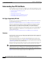
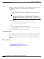
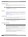
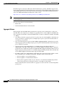
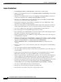
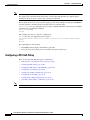
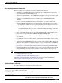
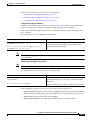
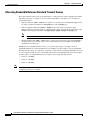
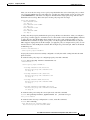
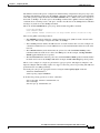
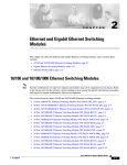
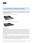
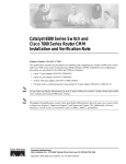
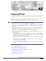
Figure 42-1 shows an overview of QoS processing in a Cisco 7600 series router.
Cisco 7600 Series Router Cisco IOS Software Configuration Guide, Release 12.2SX
42-2
OL-4266-08
Chapter 42
Configuring PFC QoS
Understanding How PFC QoS Works
Figure 42-1 PFC QoS Feature Processing Overview
MSFC
2
PFC
1
Switching
Module
3
120559
Switching
Module
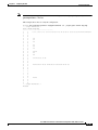
The PFC QoS features are applied in this order:
1.
Ingress port PFC QoS features:
– Port trust state—In PFC QoS, trust means to accept as valid and use as the basis of the initial
internal DSCP value. Ports are untrusted by default, which sets the initial internal DSCP value
to zero. You can configure ports to trust received CoS, IP precedence, or DSCP.
– Layer 2 CoS remarking—PFC QoS applies Layer 2 CoS remarking, which marks the incoming
frame with the port CoS value, in these situations:
—If the traffic is not in an ISL, 802.1Q, or 802.1p frame.
—If a port is configured as untrusted.
On OSM ATM and POS ports, PFC QoS always sets ingress CoS equal to zero.
– Congestion avoidance—If you configure an Ethernet LAN port to trust CoS or DSCP, QoS
classifies the traffic on the basis of its Layer 2 CoS value or its Layer 3 DSCP value and assigns
it to an ingress queue to provide congestion avoidance. Layer 3 DSCP-based queue mapping is
available only on WS-X6708-10GE ports.
2.
PFC and DFC QoS features:
– Internal DSCP—On the PFC and DFCs, QoS associates an internal DSCP value with all traffic
to classify it for processing through the system. There is an initial internal DSCP based on the
traffic trust state and a final internal DSCP. The final internal DSCP can be the same as the
initial value or an MQC policy map can set it to a different value.
– MQC policy maps—MQC policy maps can do one or more of these operations:
—Change the trust state of the traffic (bases the internal DSCP value on a different QoS label)
—Set the initial internal DSCP value (only for traffic from untrusted ports)
—Mark the traffic
—Police the traffic
3.
Egress Ethernet LAN port QoS features:
– Layer 3 DSCP marking with the final internal DSCP (always with PFC2, optionally with PFC3)
– Layer 2 CoS marking mapped from the final internal DSCP
– Layer 2 CoS-based and Layer 3 DSCP-based congestion avoidance. (Layer 3 DSCP-based
queue mapping is available only on WS-X6708-10GE ports.)
Cisco 7600 Series Router Cisco IOS Software Configuration Guide, Release 12.2SX
OL-4266-08
42-3
Chapter 42
Configuring PFC QoS
Understanding How PFC QoS Works
These figures provide more detail about the relationship between QoS and the router components:
•
Figure 42-2, Traffic Flow and PFC QoS Features with PFC3
•
Figure 42-3, Traffic Flow and PFC QoS Features with PFC2
•
Figure 42-4, PFC QoS Features and Component Overview
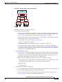
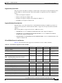
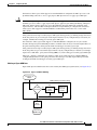
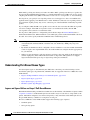
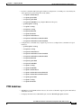
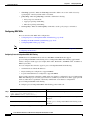
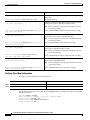
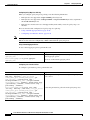
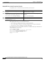
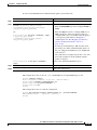
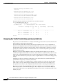
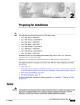
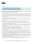
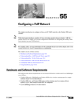
Figure 42-2 shows traffic flow and PFC QoS features with a PFC3.
Figure 42-2 Traffic Flow and PFC QoS Features with PFC3
Multilayer Switch
Feature Card
(MSFC)
FlexWAN
ingress port and
QoS features
FlexWAN traffic
enters switch
FlexWAN
egress port and
QoS features
Transmit
FlexWAN traffic
LAN traffic
enters switch
LAN ingress
port and
QoS features
OSM traffic
enters switch
OSM ingress
port and
QoS freatures
Ingress
PFC3
QoS
PFC3
Layer 2 or 3
switching
Egress
PFC3
QoS
LAN egress
port and
QoS features
Transmit
LAN traffic
OSM egress
port and
QoS freatures
Transmit
OSM traffic
105757
CoS = IP precedence for all traffic
(not configurable)
CoS = 0 for all ATM and POS traffic (not configurable)
Figure 42-2 shows how traffic flows through the PFC QoS features with PFC3:
•
Traffic can enter on any type of port and exit on any type of port.
•
DFCs implement PFC QoS locally on switching modules.
•
For FlexWAN module traffic:
– Ingress FlexWAN QoS features can be applied to FlexWAN ingress traffic.
– Ingress FlexWAN traffic can be Layer 3-switched by the PFC3 or routed in software by the MSFC.
– Egress PFC QoS is not applied to FlexWAN ingress traffic.
– Egress FlexWAN QoS can be applied to FlexWAN egress traffic.
•
For LAN-port traffic:
– Ingress LAN-port QoS features can be applied to LAN-port ingress traffic.
– Ingress PFC QoS can be applied to LAN-port ingress traffic.
– Ingress LAN-port traffic can be Layer-2 or Layer-3 switched by the PFC3 or routed in software
by the MSFC.
– Egress PFC QoS and egress LAN-port QoS can be applied to LAN-port egress traffic.
•
For OSM traffic:
– Ingress OSM-port QoS features can be applied to OSM-port ingress traffic.
– Ingress PFC3 QoS can be applied to OSM-port ingress traffic.
– Ingress OSM-port traffic can be Layer-3 switched by the PFC3 or routed in software by the MSFC.
– Egress PFC3 QoS and egress OSM-port QoS can be applied to OSM-port egress traffic.
Cisco 7600 Series Router Cisco IOS Software Configuration Guide, Release 12.2SX
42-4
OL-4266-08
Chapter 42
Configuring PFC QoS
Understanding How PFC QoS Works
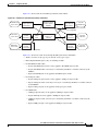
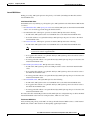
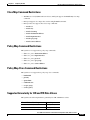
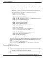
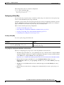
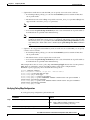
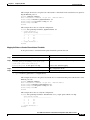
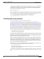
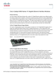
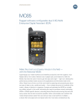
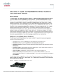
Figure 42-3 shows traffic flow and PFC QoS features with a PFC2.
Figure 42-3 Traffic Flow and PFC QoS Features with PFC2
FlexWAN traffic
enters switch
Multilayer Switch
Feature Card 2
(MSFC2)
FlexWAN
ingress port and
QoS features
FlexWAN
egress port and
QoS features
Transmit
FlexWAN traffic
LAN traffic
enters switch
LAN ingress
port and
QoS features
OSM traffic
enters switch
OSM ingress
port and
QoS freatures
Ingress
PFC2
QoS
PFC2
Layer 2 or 3
switching
LAN egress
port and
QoS features
Transmit
LAN traffic
OSM egress
port and
QoS freatures
Transmit
OSM traffic
120185
CoS = IP precedence for all traffic
(not configurable)
CoS = 0 for all ATM and POS traffic (not configurable)
Figure 42-3 shows how traffic flows through the PFC QoS features with PFC2:
•
Traffic can enter on any type of port and exit on any type of port.
•
DFCs implement PFC QoS locally on switching modules.
•
For FlexWAN module traffic:
– Ingress FlexWAN QoS features can be applied to FlexWAN ingress traffic.
– Ingress FlexWAN traffic can be Layer 3-switched by the PFC2 or routed in software by the
MSFC2.
– Egress FlexWAN QoS can be applied to FlexWAN egress traffic.
•
For LAN-port traffic:
– Ingress LAN-port QoS features can be applied to LAN-port ingress traffic.
– Ingress LAN-port traffic can be Layer-2 or Layer-3 switched by the PFC2 or routed in software
by the MSFC2.
– Egress LAN-port QoS can be applied to LAN-port egress traffic.
•
For OSM traffic:
– OSM-port QoS features can be applied to OSM-port ingress traffic.
– Ingress PFC2 QoS can be applied to OSM-port ingress traffic.
– OSM-port ingress traffic can be Layer-3 switched by the PFC2 or routed in software by the
MSFC2.
– Egress OSM-port QoS can be applied to OSM-port egress traffic.
Cisco 7600 Series Router Cisco IOS Software Configuration Guide, Release 12.2SX
OL-4266-08
42-5
Chapter 42
Configuring PFC QoS
Understanding How PFC QoS Works
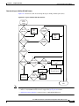
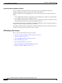
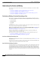
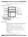
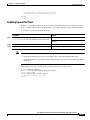
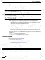
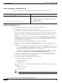
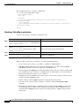
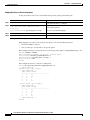
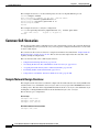
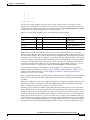
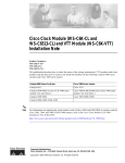
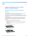
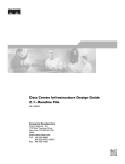
Figure 42-4 PFC QoS Features and Component Overview
DSCP
map
Ingress Port
Incoming
ToS
CoS
Q1
Scheduler
Q2
Final internal
DSCP is
mapped to CoS
PFC/DFC
C
l
a
s
s
i
f
i
c
a
t
i
o
n
Egress Port
Q1
Queueing based on CoS
SP
Outgoing
Q2
Policy
Result
DSCP
CoS
rewrite
CoS determies
queue selection
Action - policy map
Scheduling rules: WRR, PQ
Scheduler operates
on WRR, DWRR,
SP
Trust - DSCP, IP Prec
MPLS Exp
Q3
WRR
DWRR
Q4
CoS set on
trunk port
DSCP set
for IP
Scheduler queue
and threshold are
configurable
Mark - set internal
DSCP
Police - rate limit; mark; drop
137031
Port Trust
- CoS
- IP Prec
- DSCP
- MPLS Exp
Identify traffic
based on match
criteria:
- ACL (L2, IP)
- DSCP
- IP Prec
- MPLS Exp
- Class-map
Component Overview
These sections provide more detail about the role of the following components in PFC QoS decisions
and processes:
•
Ingress LAN Port PFC QoS Features, page 42-6
•
PFC and DFC QoS Features, page 42-8
•
PFC QoS Egress Port Features, page 42-12
Ingress LAN Port PFC QoS Features
These sections provide an overview of the ingress port QoS features:
•
Flowchart of Ingress LAN Port PFC QoS Features, page 42-7
•
Port Trust, page 42-8
•
Ingress Congestion Avoidance, page 42-8
Cisco 7600 Series Router Cisco IOS Software Configuration Guide, Release 12.2SX
42-6
OL-4266-08
Chapter 42
Configuring PFC QoS
Understanding How PFC QoS Works
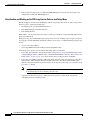
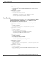
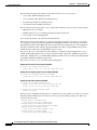
Flowchart of Ingress LAN Port PFC QoS Features
Figure 42-5 shows how traffic flows through the ingress LAN port PFC QoS features.
Figure 42-5 Ingress LAN Port PFC QoS Features
Frame
enters
switch
ISL or
802.1Q?
No
IP
traffic with No
recognizable
ToS byte?
Apply
port
CoS
Yes
Apply
port
CoS
Yes
Ignore
port trust
enabled?
Port set to Yes
untrusted?
No
No
Port set to
trust-ipprec?
Yes
No
Port set to Yes
trust-dscp?
No
IP
traffic
with Yes
DSCP-based Yes
recognizable
queue mapping
ToS byte?
enabled?
DSCP-to-queue
map
No
No
No
Ingress Yes
CoS
Mutation?
Ingress queues and
drop thresholds
Mutate
CoS
154684
Port is set to
trust-cos
CoS-to-queue
map
To
PFC
Note
•
Ingress CoS mutation is supported only on 802.1Q tunnel ports.
•
Release 12.2(18)SXF5 and later releases support the ignore port trust feature.
•
DSCP-based queue mapping is supported only on WS-X6708-10GE ports.
Cisco 7600 Series Router Cisco IOS Software Configuration Guide, Release 12.2SX
OL-4266-08
42-7
Chapter 42
Configuring PFC QoS
Understanding How PFC QoS Works
Port Trust
In PFC QoS, trust means to accept as valid and use as the basis of the initial internal DSCP value. You
can configure ports as untrusted or you can configure them to trust these QoS values:
•
Layer 2 CoS
– A port configured to trust CoS is called a trust CoS port.
– Traffic received through a trust CoS port or configured by a policy map to trust CoS is called
trust CoS traffic.
Not all traffic carries a CoS value. Only ISL, 802.1Q, and 802.1P traffic carries a CoS value.
PFC QoS applies the port CoS value to any traffic that does not carry a CoS value. On
untrusted ports, PFC QoS applies the port CoS value to all traffic, overwriting any received
CoS value.
Note
•
IP precedence
– A port configured to trust IP precedence is called a trust IP precedence port.
– Traffic received through a trust IP precedence port or configured by a policy map to trust
IP precedence is called trust IP precedence traffic.
•
DSCP
– A port configured to trust DSCP is called a trust DSCP port.
– Traffic received through a trust DSCP port or configured by a policy map to trust DSCP is called
trust DSCP traffic.
Traffic received through an untrusted port is called untrusted traffic.
Ingress Congestion Avoidance
PFC QoS implements congestion avoidance on trust CoS ports. On a trust CoS port, QoS classifies the
traffic on the basis of its Layer 2 CoS value and assigns it to an ingress queue to provide congestion
avoidance. In Release 12.2(18)SXF5 and later releases, you can configure WS-X6708-10GE trust DSCP
ports to use received DSCP values for congestion avoidance. See the “Ingress Classification and
Marking at Trust CoS LAN Ports” section on page 42-17 for more information about ingress congestion
avoidance.
PFC and DFC QoS Features
These sections describe PFCs and DFCs as they relate to QoS:
•
Supported Policy Feature Cards, page 42-9
•
Supported Distributed Forwarding Cards, page 42-9
•
PFC and DFC QoS Feature List and Flowchart, page 42-9
•
Internal DSCP Values, page 42-11
Cisco 7600 Series Router Cisco IOS Software Configuration Guide, Release 12.2SX
42-8
OL-4266-08
Chapter 42
Configuring PFC QoS
Understanding How PFC QoS Works
Supported Policy Feature Cards
The policy feature card (PFC) is a daughter card that resides on the supervisor engine. The PFC provides
QoS in addition to other functionality. The following PFCs are supported on the Cisco 7600 series
routers:
•
PFC2 on the Supervisor Engine 2
•
PFC3A on the Supervisor Engine 720
•
PFC3B on the Supervisor Engine 720 and Supervisor Engine 32
•
PFC3BXL on the Supervisor Engine 720
Supported Distributed Forwarding Cards
The PFC sends a copy of the QoS policies to the distributed forwarding card (DFC) to provide local
support for the QoS policies, which enables the DFCs to support the same QoS features that the PFC
supports.
The following DFCs are supported on the Cisco 7600 series routers:
•
WS-F6K-DFC, for use on dCEF256 and CEF256 modules with a Supervisor Engine 2.
•
WS-F6K-DFC3A, WS-F6K-DFC3B, WS-F6K-DFC3BXL, for use on dCEF256 and CEF256
modules with a Supervisor Engine 720.
•
WS-F6700-DFC3A, WS-F6700-DFC3B, WS-F6700-DFC3BXL, for use on CEF720 modules with
a Supervisor Engine 720.
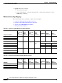
PFC and DFC QoS Feature List and Flowchart
Table 42-1 lists the QoS features supported on the different versions of PFCs and DFCs.
Table 42-1 QoS Features Supported on PFCs and DFCs
Feature
PFC2/DFC
PFC3A/DFC3A
PFC3B/DFC3B
PFC3BXL/DFC3BXL
Support for DFCs
Yes
Yes
Yes
Yes
Flow granularity
Full flow
Source
Destination
Source
Destination
Source
Destination
QoS ACLs
IP, IPX, MAC
IP, MAC
IP, MAC
IP, MAC
DSCP transparency
No
Optional
Optional
Optional
Mandatory
Optional
Optional
Optional
Ingress aggregate policers
Yes
Yes
Yes
Yes
Egress aggregate policers
No
Yes
Yes
Yes
Number of aggregate policers
1022
1022
1022
1022
Microflow policers
64 rates
64 rates
64 rates
64 rates
Number of flows per Microflow policer
32,000
64,000
110,000
240,000
Unit of measure for policer statistics
Packets
Bytes
Bytes
Bytes
Basis of policer operation
Layer 3 length Layer 2 length Layer 2 length Layer 2 length
Note
Enabling DSCP transparency disables
egress ToS rewrite.
Egress ToS rewrite
Policing:
Cisco 7600 Series Router Cisco IOS Software Configuration Guide, Release 12.2SX
OL-4266-08
42-9
Chapter 42
Configuring PFC QoS
Understanding How PFC QoS Works
Figure 42-6 shows how traffic flows through the QoS features on the PFC and DFCs.
Figure 42-6 QoS Features on the PFC and DFCs
Ingress PFC QoS
For trust CoS traffic:
Policy map
Map
CoS
(Received or Port)
Initial
Internal
DSCP
Policer
Marker
(Optional)
For trust DSCP traffic:
Policy map
Initial
Internal
DSCP
Received
DSCP
Policer
Marker
(Optional)
For trust IP precedence traffic:
Policy map
Received IP
Precedence
Map
Initial
Internal
DSCP
Policer
Marker
Egress PFC QoS
Traffic Forwarding
MSFC routing
or
PFC Layer 3
switching
or
PFC Layer 2
switching
Egress
DSCP
Mutation
Policy map
Policer
Marker
(Optional;
only
with PFC 3)
Final
Egress
Map
Internal
DSCP
DSCP (only on PFC3)
Map
Egress CoS
(LAN ports only)
(Optional)
When ignore port trust is not configured Policy map
Initial Internal DSCP=0
Policer
Marker
When ignore port trust is configured,
received DSCP (if any) is initial internal
(Optional)
DSCP, otherwise port CoS is mapped
to initial internal DSCP
Note
154644
For untrusted traffic or
for any traffic if ignore
port trust is configured
The DSCP transparency feature makes writing the egress DSCP value into the Layer 3 ToS byte optional.
Cisco 7600 Series Router Cisco IOS Software Configuration Guide, Release 12.2SX
42-10
OL-4266-08
Chapter 42
Configuring PFC QoS
Understanding How PFC QoS Works
Internal DSCP Values
During processing, PFC QoS represents the priority of all traffic (including non-IP traffic) with an
internal DSCP value.
Initial Internal DSCP Value
On the PFC, before any marking or policing takes place, PFC QoS derives the initial internal DSCP value
as follows:
•
For untrusted traffic, when ignore port trust is not enabled, PFC QoS sets the initial internal DSCP
value to zero for both tagged and untagged untrusted traffic.
•
For untrusted traffic, when ignore port trust is enabled, PFC QoS does the following:
– For IP traffic, PFC QoS uses the received DSCP value as the initial internal DSCP value.
– For traffic without a recognizable ToS byte, PFC QoS maps the port CoS value to the initial
internal DSCP value.
•
For trust CoS traffic, when ignore port trust is enabled, PFC QoS does the following:
– For IP traffic, PFC QoS uses the received DSCP value as the initial internal DSCP value.
Note
For trust CoS traffic, when ignore port trust is enabled, PFC QoS does not use the
received CoS value in tagged IP traffic.
– For tagged traffic without a recognizable ToS byte, PFC QoS maps the received CoS value to
the initial internal DSCP value.
– For untagged traffic without a recognizable ToS byte, PFC QoS maps the port CoS value to the
initial internal DSCP value.
•
For trust IP precedence traffic, PFC QoS does the following:
– For IP traffic, PFC QoS maps the received IP precedence value to the initial internal DSCP
value.
– For tagged traffic without a recognizable ToS byte, PFC QoS maps the received CoS value to
the initial internal DSCP value.
– For untagged traffic without a recognizable ToS byte, PFC QoS maps the port CoS value to the
initial internal DSCP value.
•
For trust DSCP traffic, PFC QoS, PFC QoS does the following:
– For IP traffic, PFC QoS uses the received DSCP value as the initial internal DSCP value.
– For tagged traffic without a recognizable ToS byte, PFC QoS maps the received CoS value to
the initial internal DSCP value.
– For untagged traffic without a recognizable ToS byte, PFC QoS maps the port CoS value to the
initial internal DSCP value.
For trust CoS traffic and trust IP precedence traffic, PFC QoS uses configurable maps to derive the initial
internal 6-bit DSCP value from CoS or IP precedence, which are 3-bit values.
Final Internal DSCP Value
Policy marking and policing on the PFC can change the initial internal DSCP value to a final internal
DSCP value, which is then used for all subsequently applied QoS features.
Cisco 7600 Series Router Cisco IOS Software Configuration Guide, Release 12.2SX
OL-4266-08
42-11
Chapter 42
Configuring PFC QoS
Understanding How PFC QoS Works
Port-Based PFC QoS and VLAN-Based PFC QoS
You can configure each ingress LAN port for either physical port-based PFC QoS (default) or
VLAN-based PFC QoS and attach a policy map to the selected interface.
On ports configured for port-based PFC QoS, you can attach a policy map to the ingress LAN port as
follows:
•
On a nontrunk ingress LAN port configured for port-based PFC QoS, all traffic received through the
port is subject to the policy map attached to the port.
•
On a trunking ingress LAN port configured for port-based PFC QoS, traffic in all VLANs received
through the port is subject to the policy map attached to the port.
On a nontrunk ingress LAN port configured for VLAN-based PFC QoS, traffic received through the port
is subject to the policy map attached to the port’s VLAN.
On a trunking ingress LAN port configured for VLAN-based PFC QoS, traffic received through the port
is subject to the policy map attached to the traffic’s VLAN.
PFC QoS Egress Port Features
These sections describe PFC QoS egress port features:
•
Flowchart of PFC QoS Egress LAN Port Features, page 42-13
•
Egress CoS Values, page 42-13
•
Egress DSCP Mutation with a PFC3, page 42-14
•
Egress ToS Byte, page 42-14
•
Egress PFC QoS Interfaces, page 42-14
•
Egress ACL Support for Remarked DSCP, page 42-14
•
Marking on Egress OSM Ports, page 42-15
Cisco 7600 Series Router Cisco IOS Software Configuration Guide, Release 12.2SX
42-12
OL-4266-08
Chapter 42
Configuring PFC QoS
Understanding How PFC QoS Works
Flowchart of PFC QoS Egress LAN Port Features
Figure 42-7 shows how traffic flows through the QoS features on egress LAN ports.
Figure 42-7 Egress LAN Port Scheduling, Congestion Avoidance, and Marking
From
PFC or MSFC
PFC3
only
Egress queues and
drop thresholds
IP traffic Yes
from PFC?
Yes
Write ToS
byte into
packet
No
No
ISL or
802.1Q?
DSCP
rewrite
enabled?
Yes
Write CoS
into
frame
144806
No
Transmit
frame
Egress CoS Values
For all egress traffic, PFC QoS uses a configurable map to derive a CoS value from the final internal
DSCP value associated with the traffic. PFC QoS sends the derived CoS value to the egress LAN ports
for use in classification and congestion avoidance and to be written into ISL and 802.1Q frames.
Note
With Release 12.2(18)SXF5 and later releases, you can configure WS-X6708-10GE ports to use the final
internal DSCP value for egress LAN port classification and congestion avoidance (see the “Configuring
DSCP-Based Queue Mapping” section on page 42-98).
Cisco 7600 Series Router Cisco IOS Software Configuration Guide, Release 12.2SX
OL-4266-08
42-13
Chapter 42
Configuring PFC QoS
Understanding How PFC QoS Works
Egress DSCP Mutation with a PFC3
With a PFC3, you can configure 15 egress DSCP mutation maps to mutate the internal DSCP value
before it is written in the egress ToS byte. You can attach egress DSCP mutation maps to any interface
that PFC QoS supports.
Note
•
If you configure egress DSCP mutation, PFC QoS does not derive the egress CoS value from the
mutated DSCP value.
•
The PFC2 does not support egress DSCP mutation.
Egress ToS Byte
Except when DSCP transparency is enabled, PFC QoS creates a ToS byte for egress IP traffic from the
final internal or mutated DSCP value and sends it to the egress port to be written into IP packets. For
trust DSCP and untrusted IP traffic, the ToS byte includes the original two least-significant bits from the
received ToS byte.
The internal or mutated DSCP value can mimic an IP precedence value (see the “IP Precedence and
DSCP Values” section on page 42-55).
Egress PFC QoS Interfaces
You can attach an output policy map to a Layer 3 interface (either a LAN port configured as a Layer 3
interface or a VLAN interface) to apply a policy map to egress traffic.
Note
•
Output policies do not support microflow policing.
•
With a PFC3, you cannot apply microflow policing to ARP traffic.
•
You cannot set a trust state in an output policy.
Egress ACL Support for Remarked DSCP
Note
Egress ACL support for remarked DSCP is also known as packet recirculation.
With a PFC3, Release 12.2(18)SXE and later releases support egress ACL support for remarked DSCP,
which enables IP precedence-based or DSCP-based egress QoS filtering to use any IP precedence or
DSCP policing or marking changes made by ingress PFC QoS.
Without egress ACL support for remarked DSCP, egress QoS filtering uses received IP precedence or
DSCP values; it does not use any IP precedence or DSCP changes made by ingress PFC QoS as the result
of policing or marking.
The PFC3 provides egress PFC QoS only for Layer 3-switched and routed traffic on egress Layer 3
interfaces (either LAN ports configured as Layer 3 interfaces or VLAN interfaces).
You configure egress ACL support for remarked DSCP on ingress Layer 3 interfaces (either LAN ports
configured as Layer 3 interfaces or VLAN interfaces).
Cisco 7600 Series Router Cisco IOS Software Configuration Guide, Release 12.2SX
42-14
OL-4266-08
Chapter 42
Configuring PFC QoS
Understanding How PFC QoS Works
On interfaces where egress ACL support for remarked DSCP is configured, the PFC3 processes each
QoS-filtered IP packet twice: once to apply ingress PFC QoS and once to apply egress PFC QoS.
Caution
If the router is operating in PFC3A mode with egress ACL support for remarked DSCP configured, when
the PFC3 processes traffic to apply ingress PFC QoS, it applies ingress PFC QoS filtering and ingress
PFC QoS, and incorrectly applies any egress QoS filtering and egress PFC QoS configured on the
ingress interface, which results in unexpected behavior if QoS filtering is configured on an interface
where egress ACL support for remarked DSCP is enabled. This problem does not occur in other
PFC3 modes.
After packets have been processed by ingress PFC QoS and any policing or marking changes have been
made, the packets are processed again on the ingress interface by any configured Layer 2 features (for
example, VACLs) before being processed by egress PFC QoS.
On an interface where egress ACL support for remarked DSCP is configured, if a Layer 2 feature
matches the ingress-QoS-modified IP precedence or DSCP value, the Layer 2 feature might redirect or
drop the matched packets, which prevents them from being processed by egress QoS.
After packets have been processed by ingress PFC QoS and any policing or marking changes have been
made, the packets are processed on the ingress interface by any configured Layer 3 features (for example,
ingress Cisco IOS ACLs, policy based routing (PBR), etc.) before being processed by egress PFC QoS.
The Layer 3 features configured on an interface where egress ACL support for remarked DSCP is
configured might redirect or drop the packets that have been processed by ingress PFC QoS, which
would prevent them from being processed by egress PFC QoS.
Marking on Egress OSM Ports
Ingress PFC QoS sets DSCP values that can be used by the OSM egress QoS features (see Figure 42-8).
Figure 42-8 Egress OSM Port Marking
From PFC or
MSFC
OSM switching module marking
PFC3
only
IP traffic
Yes
from PFC?
DSCP
rewrite
enabled?
Yes
Write ToS
byte into
packet
No
113090
No
OSM
QoS
Features
Transmit
OSM traffic
Cisco 7600 Series Router Cisco IOS Software Configuration Guide, Release 12.2SX
OL-4266-08
42-15
Chapter 42
Configuring PFC QoS
Understanding How PFC QoS Works
Understanding Classification and Marking
The following sections describe where and how classification and marking occur on the Cisco 7600
series routers:
•
Classification and Marking at Trusted and Untrusted Ingress Ports, page 42-16
•
Classification and Marking at Ingress OSM Ports, page 42-17
•
Classification and Marking on the PFC Using Service Policies and Policy Maps, page 42-18
•
Classification and Marking on the MSFC, page 42-19
Classification and Marking at Trusted and Untrusted Ingress Ports
The trust state of an ingress port determines how the port marks, schedules, and classifies received
Layer 2 frames, and whether or not congestion avoidance is implemented. These are the port trust states:
•
Untrusted (default)
•
Trust IP precedence
•
Trust DSCP
•
Trust CoS
In all releases, ingress LAN port classification, marking, and congestion avoidance can use Layer 2 CoS
values and do not set Layer 3 IP precedence or DSCP values.
In Release 12.2(18)SXF5 and later releases, you can configure WS-X6708-10GE ports to use received
DSCP values for ingress LAN port classification and congestion avoidance (see the “Configuring
DSCP-Based Queue Mapping” section on page 42-98)
In Releases earlier than Release 12.2(18)SXF5, ingress LAN port classification, marking, and
congestion avoidance use Layer 2 CoS values only.
The following sections describe classification and marking at trusted and untrusted ingress ports:
•
Classification and Marking at Untrusted Ingress Ports, page 42-16
•
Ingress Classification and Marking at Trusted Ports, page 42-16
Classification and Marking at Untrusted Ingress Ports
PFC QoS Layer 2 remarking marks all frames received through untrusted ports with the port CoS value
(the default is zero).
To map the port CoS value that was applied to untrusted ingress traffic to the initial internal DSCP value,
configure a trust CoS policy map that matches the ingress traffic.
Ingress Classification and Marking at Trusted Ports
You should configure ports to trust only if they receive traffic that carries valid QoS labels. QoS uses the
received QoS labels as the basis of initial internal DSCP value. After the traffic enters the router, you
can apply a different trust state to traffic with a policy map. For example, traffic can enter the router
through a trust CoS port, and then you can use a policy map to trust IP precedence or DSCP, which uses
the trusted value as the basis of the initial internal DSCP value, instead of the QoS label that was trusted
at the port.
Cisco 7600 Series Router Cisco IOS Software Configuration Guide, Release 12.2SX
42-16
OL-4266-08
Chapter 42
Configuring PFC QoS
Understanding How PFC QoS Works
These sections describe classification and marking at trusted ingress ports:
•
Ingress Classification and Marking at Trust CoS LAN Ports, page 42-17
•
Ingress Classification and Marking at Trust IP Precedence Ports, page 42-17
•
Ingress Classification and Marking at Trust DSCP Ports, page 42-17
Ingress Classification and Marking at Trust CoS LAN Ports
You should configure LAN ports to trust CoS only if they receive traffic that carries valid Layer 2 CoS.
When an ISL frame enters the router through a trusted ingress LAN port, PFC QoS accepts the three least
significant bits in the User field as a CoS value. When an 802.1Q frame enters the router through a
trusted ingress LAN port, PFC QoS accepts the User Priority bits as a CoS value. PFC QoS Layer 2
remarking marks all traffic received in untagged frames with the ingress port CoS value.
On ports configured to trust CoS, PFC QoS does the following:
•
PFC QoS maps the received CoS value in tagged trust CoS traffic to the initial internal DSCP value.
•
PFC QoS maps the ingress port CoS value applied to untagged trusted traffic to the initial internal
DSCP value.
•
PFC QoS enables the CoS-based ingress queues and thresholds to provide congestion avoidance.
See the “Understanding Port-Based Queue Types” section on page 42-22 for more information about
ingress queues and thresholds.
Ingress Classification and Marking at Trust IP Precedence Ports
You should configure ports to trust IP precedence only if they receive traffic that carries valid Layer 3
IP precedence. For traffic from trust IP precedence ports, PFC QoS maps the received IP precedence
value to the initial internal DSCP value. Because the ingress port queues and thresholds use Layer 2 CoS,
PFC QoS does not implement ingress port congestion avoidance on ports configured to trust IP
precedence. PFC does not mark any traffic on ingress ports configured to trust IP precedence.
Ingress Classification and Marking at Trust DSCP Ports
You should configure ports to trust DSCP only if they receive traffic that carries valid Layer 3 DSCP.
In Release 12.2(18)SXF5 and later releases, you can enable DSCP-based ingress queues and thresholds
on WS-X6708-10GE ports to provide congestion avoidance (see the “Configuring DSCP-Based Queue
Mapping” section on page 42-98).
In releases earlier than Release 12.2(18)SXF5, the ingress port queues and thresholds use only Layer 2
CoS, and PFC QoS does not implement ingress port congestion avoidance on ports configured to trust
DSCP.
For traffic from trust DSCP ports, PFC QoS uses the received DSCP value as the initial internal DSCP
value. PFC QoS does not mark any traffic on ingress ports configured to trust received DSCP.
Classification and Marking at Ingress OSM Ports
PFC QoS associates CoS zero with all traffic received through ingress OSM ports. You can configure
ingress OSM port trust states that can be used by the PFC to set IP precedence or DSCP values and the
CoS value. You can configure the trust state of each ingress OSM port as follows:
•
Untrusted (default)
•
Trust IP precedence
•
Trust DSCP
Cisco 7600 Series Router Cisco IOS Software Configuration Guide, Release 12.2SX
OL-4266-08
42-17
Chapter 42
Configuring PFC QoS
Understanding How PFC QoS Works
•
Trust CoS (CoS is always zero for POS and ATM OSM ports because the port CoS value is not
configurable on POS and ATM OSM ports.)
Classification and Marking on the PFC Using Service Policies and Policy Maps
PFC QoS supports classification and marking with service policies that attach one policy map to these
interface types to apply ingress PFC QoS:
•
Each ingress port (except FlexWAN interfaces)
•
Each EtherChannel port-channel interface
•
Each VLAN interface
With a PFC3, you can attach one policy map to each Layer 3 interface (except FlexWAN interfaces) to
apply egress PFC QoS.
Each policy map can contain multiple policy-map classes. You can configure a separate policy-map class
for each type of traffic handled by the interface. There are two ways to configure filtering in policy-map
classes:
•
Access control lists (ACLs)
•
Class-map match commands for IP precedence and DSCP values
Policy-map classes specify actions with the following optional commands:
•
Policy-map set commands—For untrusted traffic or if ignore port trust is enabled, PFC QoS can use
configured IP precedence or DSCP values as the final internal DSCP value. The “IP Precedence and
DSCP Values” section on page 42-55 shows the bit values for IP precedence and DSCP.
•
Policy-map class trust commands—PFC QoS applies the policy-map class trust state to matched
ingress traffic, which then uses the trusted value as the basis of its initial internal DSCP value,
instead of the QoS label that was trusted at the port (if any). In a policy map, you can trust CoS, IP
precedence, or DSCP.
Note
•
A trust CoS policy map cannot restore received CoS in traffic from untrusted ports. Traffic
from untrusted ports always has the port CoS value.
Aggregate and microflow policers—PFC QoS can use policers to either mark or drop both
conforming and nonconforming traffic.
Cisco 7600 Series Router Cisco IOS Software Configuration Guide, Release 12.2SX
42-18
OL-4266-08
Chapter 42
Configuring PFC QoS
Understanding How PFC QoS Works
Classification and Marking on the MSFC
PFC QoS sends IP traffic to the MSFC with the final internal DSCP values. CoS is equal to
IP precedence in all traffic sent from the MSFC to egress ports.
Figure 42-9 Marking with PFC2 or PFC3 and MSFC2, MSFC2A, or MSFC3
From PFC
Multilayer Switch Feature Card (MSFC) marking
IP traffic Yes
from PFC?
Write ToS
byte into
packet
No
144800
Route
traffic
CoS = IP precedence for
all traffic (not configurable)
To egress
port
Note
Traffic that is Layer 3 switched on the PFC does not go through the MSFC and retains the CoS value
assigned by the PFC.
Policers
These sections describe policers:
•
Overview of Policers, page 42-19
•
Aggregate Policers, page 42-20
•
Microflow Policers, page 42-21
Overview of Policers
Policing allows you to rate limit incoming and outgoing traffic so that it adheres to the traffic forwarding
rules defined by the QoS configuration. Sometimes these configured rules for how traffic should be
forwarded through the system are referred to as a contract. If the traffic does not adhere to this contract,
it is marked down to a lower DSCP value or dropped.
Policing does not buffer out-of-profile packets. As a result, policing does not affect transmission delay.
In contrast, traffic shaping works by buffering out-of-profile traffic, which moderates the traffic bursts.
(PFC QoS does not support shaping.)
Cisco 7600 Series Router Cisco IOS Software Configuration Guide, Release 12.2SX
OL-4266-08
42-19
Chapter 42
Configuring PFC QoS
Understanding How PFC QoS Works
The PFC2 supports only ingress PFC QoS, which includes ingress policing. The PFC3 supports both
ingress and egress PFC QoS, which includes ingress and egress policing. Traffic shaping is supported on
some WAN modules. For more information about traffic shaping on the OSM and FlexWAN modules,
refer to the OSM and FlexWAN documentation at this location:
http://www.cisco.com/univercd/cc/td/doc/product/core/cis7600/cfgnotes/index.htm
Note
Policers can act on ingress traffic per-port or per-VLAN. With a PFC3, for egress traffic, the policers can
act per-VLAN only.
You can create policers to do the following:
•
Mark traffic
•
Limit bandwidth utilization and mark traffic
Aggregate Policers
PFC QoS applies the bandwidth limits specified in an aggregate policer cumulatively to all flows in
matched traffic. For example, if you configure an aggregate policer to allow 1 Mbps for all TFTP traffic
flows on VLAN 1 and VLAN 3, it limits the TFTP traffic for all flows combined on VLAN 1 and VLAN
3 to 1 Mbps.
•
You define per-interface aggregate policers in a policy map class with the police command. If you
attach a per-interface aggregate policer to multiple ingress ports, it polices the matched traffic on
each ingress port separately.
•
You create named aggregate policers with the mls qos aggregate-policer command. If you attach a
named aggregate policer to multiple ingress ports, it polices the matched traffic from all the ingress
ports to which it is attached.
•
Aggregate policing works independently on each DFC-equipped switching module and
independently on the PFC, which supports any non-DFC-equipped switching modules. Aggregate
policing does not combine flow statistics from different DFC-equipped switching modules. You can
display aggregate policing statistics for each DFC-equipped switching module and for the PFC and
any non-DFC-equipped switching modules supported by the PFC.
•
Each PFC or DFC polices independently, which might affect QoS features being applied to traffic
that is distributed across the PFC and any DFCs. Examples of these QoS feature are:
– Policers applied to a port channel interface.
– Policers applied to a switched virtual interface.
– Egress policers applied to either a Layer 3 interface or an SVI. Note that PFC QoS performs
egress policing decisions at the ingress interface, on the PFC or ingress DFC.
Policers affected by this restriction deliver an aggregate rate that is the sum of all the independent
policing rates.
Cisco 7600 Series Router Cisco IOS Software Configuration Guide, Release 12.2SX
42-20
OL-4266-08
Chapter 42
Configuring PFC QoS
Understanding How PFC QoS Works
Microflow Policers
PFC QoS applies the bandwidth limit specified in a microflow policer separately to each flow in matched
traffic. For example, if you configure a microflow policer to limit the TFTP traffic to 1 Mbps on VLAN
1 and VLAN 3, then 1 Mbps is allowed for each flow in VLAN 1 and 1 Mbps for each flow in VLAN 3.
In other words, if there are three flows in VLAN 1 and four flows in VLAN 3, the microflow policer
allows each of these flows 1 Mbps.
You can configure PFC QoS to apply the bandwidth limits in a microflow policer as follows:
•
You can create microflow policers with up to 63 different rate and burst parameter combinations.
•
You create microflow policers in a policy map class with the police flow command.
•
You can configure a microflow policer to use only source addresses, which applies the microflow
policer to all traffic from a source address regardless of the destination addresses.
•
You can configure a microflow policer to use only destination addresses, which applies the
microflow policer to all traffic to a destination address regardless of the source addresses.
•
For MAC-Layer microflow policing, PFC QoS considers MAC-Layer traffic with the same protocol
and the same source and destination MAC-Layer addresses to be part of the same flow, including
traffic with different EtherTypes. With a PFC3, you can configure MAC ACLs to filter IPX traffic.
•
With a PFC2, you can configure IPX ACLs to filter IPX traffic. For IPX microflow policing,
PFC QoS considers IPX traffic with the same source network, destination network, and destination
node to be part of the same flow, including traffic with different source nodes or source sockets.
•
By default, microflow policers only affect traffic routed by the MSFC. To enable microflow policing
of other traffic, including traffic in bridge groups, enter the mls qos bridged command. With a
PFC2, you must enable bridged mircoflow policing for routed traffic as well.
•
With a PFC3, you cannot apply microflow policing to ARP traffic.
•
You cannot apply microflow policing to IPv6 multicast traffic.
You can include both an aggregate policer and a microflow policer in each policy map class to police a
flow based on both its own bandwidth utilization and on its bandwidth utilization combined with that of
other flows.
Note
If traffic is both aggregate and microflow policed, then the aggregate and microflow policers must both
be in the same policy-map class and each must use the same conform-action and exceed-action
keyword option: drop, set-dscp-transmit, set-prec-transmit, or transmit.
For example, you could create a microflow policer with a bandwidth limit suitable for individuals in a
group, and you could create a named aggregate policer with bandwidth limits suitable for the group as a
whole. You could include both policers in policy map classes that match the group’s traffic. The
combination would affect individual flows separately and the group aggregately.
For policy map classes that include both an aggregate and a microflow policer, PFC QoS responds to an
out-of-profile status from either policer and, as specified by the policer, applies a new DSCP value or
drops the packet. If both policers return an out-of-profile status, then if either policer specifies that the
packet is to be dropped, it is dropped; otherwise, PFC QoS applies a marked-down DSCP value.
Note
To avoid inconsistent results, ensure that all traffic policed by the same aggregate policer has the same
trust state.
Cisco 7600 Series Router Cisco IOS Software Configuration Guide, Release 12.2SX
OL-4266-08
42-21
Chapter 42
Configuring PFC QoS
Understanding How PFC QoS Works
With a PFC3, policing uses the Layer 2 frame size. With a PFC2, policing uses the Layer 3 packet size.
You specify the bandwidth utilization limit as a committed information rate (CIR). You can also specify
a higher peak information rate (PIR). Packets that exceed a rate are “out of profile” or “nonconforming.”
In each policer, you specify if out-of-profile packets are to be dropped or to have a new DSCP value
applied to them (applying a new DSCP value is called “markdown”). Because out-of-profile packets do
not retain their original priority, they are not counted as part of the bandwidth consumed by in-profile
packets.
If you configure a PIR, the PIR out-of-profile action cannot be less severe than the CIR out-of-profile
action. For example, if the CIR out-of-profile action is to mark down the traffic, then the PIR
out-of-profile action cannot be to transmit the traffic.
For all policers, PFC QoS uses a configurable global table that maps the internal DSCP value to a
marked-down DSCP value. When markdown occurs, PFC QoS gets the marked-down DSCP value from
the table. You cannot specify marked-down DSCP values in individual policers.
Note
•
Policing with the conform-action transmit keywords supersedes the ingress LAN port trust state
of matched traffic with trust DSCP or with the trust state defined by a trust policy-map class
command.
•
By default, the markdown table is configured so that no markdown occurs: the marked-down DSCP
values are equal to the original DSCP values. To enable markdown, configure the table appropriately
for your network.
•
When you apply both ingress policing and egress policing to the same traffic, both the input policy
and the output policy must either mark down traffic or drop traffic. PFC QoS does not support
ingress markdown with egress drop or ingress drop with egress markdown.
Understanding Port-Based Queue Types
Port-based queue types are determined by the ASICs that control the ports. The following sections
describe the queue types, drop thresholds, and buffers that are supported on the Cisco 7600 series router
LAN modules:
•
Ingress and Egress Buffers and Layer 2 CoS-Based Queues, page 42-22
•
Ingress Queue Types, page 42-24
•
Egress Queue Types, page 42-25
•
Module to Queue Type Mappings, page 42-26
Ingress and Egress Buffers and Layer 2 CoS-Based Queues
The Ethernet LAN module port ASICs have buffers that are divided into a fixed number of queues. When
congestion avoidance is enabled, PFC QoS uses the traffic’s Layer 2 CoS value to assign traffic to the
queues. The buffers and queues store frames temporarily as they transit the switch. PFC QoS allocates
the port ASIC memory as buffers for each queue on each port.
The Cisco 7600 series router LAN modules support the following types of queues:
•
Standard queues
•
Strict-priority queues
Cisco 7600 Series Router Cisco IOS Software Configuration Guide, Release 12.2SX
42-22
OL-4266-08
Chapter 42
Configuring PFC QoS
Understanding How PFC QoS Works
The Cisco 7600 series router LAN modules support the following types of scheduling algorithms
between queues:
•
Shaped round robin (SRR)—SRR allows a queue to use only the allocated bandwidth.
•
Deficit weighted round robin (DWRR)—DWRR keeps track of any lower-priority queue
under-transmission caused by traffic in a higher-priority queue and compensates in the next round.
•
Weighted Round Robin (WRR)—WRR does not explicitly reserve bandwidth for the queues. Instead,
the amount of bandwidth assigned to each queue is user configurable. The percentage or weight allocated
to a queue defines the amount of bandwidth allocated to the queue.
•
Strict-priority queueing—Strict priority queueing allows delay-sensitive data such as voice to be
dequeued and sent before packets in other queues are dequeued, giving delay-sensitive data preferential
treatment over other traffic. The router services traffic in the strict-priority transmit queue before
servicing the standard queues. After transmitting a packet from a standard queue, the switch checks
for traffic in the strict-priority queue. If the switch detects traffic in the strict-priority queue, it
suspends its service of the standard queue and completes service of all traffic in the strict-priority
queue before returning to the standard queue.
The Cisco 7600 series router LAN modules provides congestion avoidance with these types of
thresholds within a queue:
•
Weighted Random Early Detection (WRED)—On ports with WRED drop thresholds, frames with a
given QoS label are admitted to the queue based on a random probability designed to avoid buffer
congestion. The probability of a frame with a given QoS label being admitted to the queue or
discarded depends on the weight and threshold assigned to that QoS label.
For example, if CoS 2 is assigned to queue 1, threshold 2, and the threshold 2 levels are 40 percent
(low) and 80 percent (high), then frames with CoS 2 will not be dropped until queue 1 is at least
40 percent full. As the queue depth approaches 80 percent, frames with CoS 2 have an increasingly
higher probability of being discarded rather than being admitted to the queue. Once the queue is over
80 percent full, all CoS 2 frames are dropped until the queue is less than 80 percent full. The frames
the switch discards when the queue level is between the low and high thresholds are picked out at
random, rather than on a per-flow basis or in a FIFO manner. This method works well with protocols
such as TCP that can adjust to periodic packet drops by backing off and adjusting their transmission
window size.
•
Note
Tail-drop thresholds—On ports with tail-drop thresholds, frames with a given QoS label are
admitted to the queue until the drop threshold associated with that QoS label is exceeded;
subsequent frames of that QoS label are discarded until the threshold is no longer exceeded. For
example, if CoS 1 is assigned to queue 1, threshold 2, and the threshold 2 watermark is 60 percent,
then frames with CoS 1 will not be dropped until queue 1 is 60 percent full. All subsequent CoS 1
frames will be dropped until the queue is less than 60 percent full. With some port types, you can
configure the standard receive queue to use both a tail-drop and a WRED-drop threshold by mapping
a CoS value to the queue or to the queue and a threshold. The switch uses the tail-drop threshold for
traffic carrying CoS values mapped only to the queue. The switch uses WRED-drop thresholds for
traffic carrying CoS values mapped to the queue and a threshold. All LAN ports of the same type
use the same drop-threshold configuration.
In Release 12.2(18)SXF5 and later releases, you can enable DSCP-based queues and thresholds on
WS-X6708-10GE ports (see the “Configuring DSCP-Based Queue Mapping” section on page 42-98).
The combination of multiple queues and the scheduling algorithms associated with each queue allows the
switch to provide congestion avoidance.
Cisco 7600 Series Router Cisco IOS Software Configuration Guide, Release 12.2SX
OL-4266-08
42-23
Chapter 42
Configuring PFC QoS
Understanding How PFC QoS Works
Figure 42-10 illustrates the drop thresholds for a 1q4t ingress LAN port. Drop thresholds in other
configurations function similarly.
Figure 42-10 Receive Queue Drop Thresholds
Drop threshold 4: 100%
Co
S
Reserved for
CoS 6 and 7
6
d7
an
Drop threshold 3: 80%
Co
4
Co
S
CoS
0
d3
an
1
and
Drop threshold 1: 50%
d5
an
Drop threshold 2: 60%
2
Reserved for
CoS 2 and higher
S
Reserved for
CoS 4 and higher
Available for
traffic with any
CoS value
Traffic is dropped
100% available for CoS 6 and 7
80% available for CoS 4 and 5
Receive queue
(Default values shown)
50% available for CoS 0 and 1
26249
60% available for CoS 2 and 3
Ingress Queue Types
To see the queue structure of a LAN port, enter the show queueing interface {ethernet | fastethernet |
gigabitethernet | tengigabitethernet} slot/port | include type command. The command displays one of
the following architectures:
•
1q2t indicates one standard queue with one configurable tail-drop threshold and one
nonconfigurable tail-drop threshold.
•
1q4t indicates one standard queue with four configurable tail-drop thresholds.
•
1q8t indicates one standard queue with eight configurable tail-drop thresholds.
•
2q8t indicates two standard queues, each with eight configurable tail-drop thresholds.
•
8q4t indicates eight standard queues, each with four thresholds, each configurable as either
WRED-drop or tail-drop.
•
8q8t indicates eight standard queues, each with eight thresholds, each configurable as either
WRED-drop or tail-drop.
•
1p1q4t indicates:
– One strict-priority queue
– One standard queue with four configurable tail-drop thresholds.
Cisco 7600 Series Router Cisco IOS Software Configuration Guide, Release 12.2SX
42-24
OL-4266-08
Chapter 42
Configuring PFC QoS
Understanding How PFC QoS Works
•
1p1q0t indicates:
– One strict-priority queue
– One standard queue with no configurable threshold (effectively a tail-drop threshold at
100 percent).
•
1p1q8t indicates the following:
– One strict-priority queue
– One standard queue with these thresholds:
—Eight thresholds, each configurable as either WRED-drop or tail-drop
—One non configurable (100 percent) tail-drop threshold
Egress Queue Types
To see the queue structure of an egress LAN port, enter the show queueing interface {ethernet |
fastethernet | gigabitethernet | tengigabitethernet} slot/port | include type command.
The command displays one of the following architectures:
•
2q2t indicates two standard queues, each with two configurable tail-drop thresholds.
•
1p2q2t indicates the following:
– One strict-priority queue
– Two standard queues, each with two configurable WRED-drop thresholds
•
1p3q1t indicates the following:
– One strict-priority queue
– Three standard queues with these thresholds:
—One threshold configurable as either WRED-drop or tail-drop
—One nonconfigurable (100 percent) tail-drop threshold
•
1p2q1t indicates the following:
– One strict-priority queue
– Two standard queues with these thresholds:
—One WRED-drop threshold
—One non-configurable (100 percent) tail-drop threshold
•
1p3q8t indicates the following:
– One strict-priority queue
– Three standard queues, each with eight thresholds, each threshold configurable as either
WRED-drop or tail-drop
•
1p7q4t indicates the following:
– One strict-priority queue
– Seven standard queues, each with four thresholds, each threshold configurable as either
WRED-drop or tail-drop
Cisco 7600 Series Router Cisco IOS Software Configuration Guide, Release 12.2SX
OL-4266-08
42-25
Chapter 42
Configuring PFC QoS
Understanding How PFC QoS Works
•
1p7q8t indicates the following:
– One strict-priority queue
– Seven standard queues, each with eight thresholds, each threshold configurable as either
WRED-drop or tail-drop
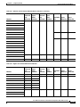
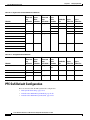
Module to Queue Type Mappings
The following tables show the module to queue structure mapping:
•
Supervisor Engine Module QoS Queue Structures
•
Ethernet and Fast Ethernet Module Queue Structures
•
Gigabit and 10/100/1000 Ethernet Modules
•
10 Gigabit Ethernet Modules
Table 42-2 Supervisor Engine Module QoS Queue Structures
Supervisor Engines
Ingress
Queue and
Drop
Thresholds
Ingress
Queue
Scheduler
Egress
Queue and
Drop
Thresholds
Egress
Queue
Scheduler
Total Buffer Ingress
Size
Buffer Size
Egress
Buffer Size
WS-SUP720
1p1q4t
—
1p2q2t
WRR
512 KB
73 KB
439 KB
2q8t
WRR
1p3q8t
DWRR
SRR
193 MB
105 MB
88 MB
17.7 MB
9.6 MB
8.1 MB
17.7 MB
9.6 MB
8.1 MB
WRR
512 KB
73 KB
439 KB
WS-SUP720-3B
WS-SUP720-3BXL
WS-SUP32-10GE
10 Gigabit Ethernet ports
Gigabit Ethernet port
WS-SUP32-GE
WS-X6K-S2U-MSFC2
1p1q4t
—
1p2q2t
WS-X6K-S2-MSFC2
WS-X6K-S2-PFC2
Table 42-3 Ethernet and Fast Ethernet Module Queue Structures
Modules
Ingress
Queue and
Drop
Thresholds
Ingress
Queue
Scheduler
Egress
Queue and
Drop
Thresholds
Egress
Queue
Scheduler
Total Buffer Ingress
Size
Buffer Size
Egress
Buffer Size
WS-X6524-100FX-MM
1p1q0t
—
1p3q1t
DWRR
1,116 KB
1,088 KB
28 KB
WS-X6548-RJ-21
WS-X6548-RJ-45
Cisco 7600 Series Router Cisco IOS Software Configuration Guide, Release 12.2SX
42-26
OL-4266-08
Chapter 42
Configuring PFC QoS
Understanding How PFC QoS Works
Table 42-3 Ethernet and Fast Ethernet Module Queue Structures (continued)
Modules
Ingress
Queue and
Drop
Thresholds
Ingress
Queue
Scheduler
Egress
Queue and
Drop
Thresholds
Egress
Queue
Scheduler
Total Buffer Ingress
Size
Buffer Size
Egress
Buffer Size
WS-X6324-100FX-MM
1q4t
—
2q2t
WRR
128 KB
16 KB
112 KB
64 KB
8 KB
56 KB
128 KB
16 KB
112 KB
WS-X6324-100FX-SM
WS-X6348-RJ-45
WS-X6348-RJ-45V
WS-X6348-RJ-21V
WS-X6224-100FX-MT
WS-X6248-RJ-45
WS-X6248-TEL
WS-X6248A-TEL
WS-X6148-RJ-45
WS-X6148-RJ-45V
WS-X6148-45AF
WS-X6148-RJ-21
WS-X6148-RJ-21V
WS-X6148-21AF
WS-X6148X2-RJ-45
1p1q0t
—
1p3q1t
DWRR
1,116 KB
28 KB
1,088 KB
1q4t
—
2q2t
WRR
64 KB
8 KB
56 KB
WS-X6148X2-45AF
WS-X6024-10FL-MT
Table 42-4 Gigabit and 10/100/1000 Ethernet Modules
Modules
Ingress
Queue and
Drop
Thresholds
Ingress
Queue
Scheduler
Egress
Queue and
Drop
Thresholds
Egress
Queue
Scheduler
Total Buffer Ingress
Size
Buffer Size
Egress
Buffer Size
WS-X6816-GBIC
1p1q4t
—
1p2q2t
WRR
512 KB
73 KB
439 KB
WS-X6748-GE-TX with DFC3 2q8t
WRR
1p3q8t
DWRR
1.3 MB
166 KB
1.2 MB
WS-X6748-GE-TX with CFC
1q8t
—
WS-X6748-SFP with DFC3
2q8t
WRR
WS-X6748-SFP with CFC
1q8t
—
WS-X6724-SFP with DFC3
2q8t
WRR
WS-X6724-SFP with CFC
1q8t
—
WS-X6548-GE-TX
1q2t
—
1p2q2t
WRR
1.4 MB
185 KB
1.2 MB
WS-X6548V-GE-TX
WS-X6548-GE-45AF
Cisco 7600 Series Router Cisco IOS Software Configuration Guide, Release 12.2SX
OL-4266-08
42-27
Chapter 42
Configuring PFC QoS
PFC QoS Default Configuration
Table 42-4 Gigabit and 10/100/1000 Ethernet Modules
Modules
Ingress
Queue and
Drop
Thresholds
Ingress
Queue
Scheduler
Egress
Queue and
Drop
Thresholds
Egress
Queue
Scheduler
Total Buffer Ingress
Size
Buffer Size
Egress
Buffer Size
WS-X6516-GBIC
1p1q4t
—
1p2q2t
WRR
512 KB
73 KB
439 KB
WS-X6516A-GBIC
WRR
1 MB
135 KB
946 KB
WS-X6516-GE-TX
WRR
512 KB
73 KB
439 KB
WS-X6408-GBIC
1q4t
—
2q2t
WRR
80 KB
432 KB
WS-X6408A-GBIC
1p1q4t
—
1p2q2t
WRR
73 KB
439 KB
1q2t
—
185 KB
1.2 MB
WS-X6416-GBIC
WS-X6416-GE-MT
WS-X6316-GE-TX
WS-X6148-GE-TX
1.4 MB
WS-X6148V-GE-TX
WS-X6148-GE-45AF
Table 42-5 10 Gigabit Ethernet Modules
Modules
Ingress
Queue and
Drop
Thresholds
Ingress
Queue
Scheduler
Egress
Queue and
Drop
Thresholds
WS-X6708-10GE
8q4t
DWRR
1p7q4t
WS-X6704-10GE with DFC3
8q8t
WRR
WS-X6704-10GE with CFC
1q8t
—
WS-X6502-10GE
1p1q8t
—
Egress
Queue
Scheduler
Total Buffer Ingress
Size
Buffer Size
Egress
Buffer Size
DWRR
SRR
198 MB
108 MB
90 MB
1p7q8t
DWRR
16 MB
2 MB
14 MB
1p2q1t
DWRR
64.2 MB
256 KB
64 MB
WS-X6501-10GEX4
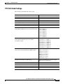
PFC QoS Default Configuration
These sections describe the PFC QoS default configuration:
•
PFC QoS Global Settings, page 42-29
•
Default Values With PFC QoS Enabled, page 42-30
•
Default Values With PFC QoS Disabled, page 42-49
Cisco 7600 Series Router Cisco IOS Software Configuration Guide, Release 12.2SX
42-28
OL-4266-08
Chapter 42
Configuring PFC QoS
PFC QoS Default Configuration
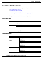
PFC QoS Global Settings
The following global PFC QoS settings apply:
Feature
Default Value
PFC QoS global enable state
Disabled
PFC QoS port enable state
Enabled when PFC QoS is globally enabled
Port CoS value
0
Microflow policing
Enabled
IntraVLAN microflow policing
Disabled
Port-based or VLAN-based PFC QoS
Port-based
Received CoS to initial internal DSCP map
(initial internal DSCP set from received CoS values)
CoS 0 = DSCP 0
CoS 1 = DSCP 8
CoS 2 = DSCP 16
CoS 3 = DSCP 24
CoS 4 = DSCP 32
CoS 5 = DSCP 40
CoS 6 = DSCP 48
CoS 7 = DSCP 56
Received IP precedence to initial internal DSCP map IP precedence 0 = DSCP 0
(initial internal DSCP set from received IP
IP precedence 1 = DSCP 8
IP precedence 2 = DSCP 16
precedence values)
IP precedence 3 = DSCP 24
IP precedence 4 = DSCP 32
IP precedence 5 = DSCP 40
IP precedence 6 = DSCP 48
IP precedence 7 = DSCP 56
Final internal DSCP to egress CoS map
(egress CoS set from final internal DSCP values)
DSCP 0–7 = CoS 0
DSCP 8–15 = CoS 1
DSCP 16–23 = CoS 2
DSCP 24–31 = CoS 3
DSCP 32–39 = CoS 4
DSCP 40–47 = CoS 5
DSCP 48–55 = CoS 6
DSCP 56–63 = CoS 7
Marked-down DSCP from DSCP map
Marked-down DSCP value equals original
DSCP value (no markdown)
Policers
None
Policy maps
None
Protocol-independent MAC ACL filtering
Disabled
VLAN-based MAC ACL QoS filtering
Disabled
Cisco 7600 Series Router Cisco IOS Software Configuration Guide, Release 12.2SX
OL-4266-08
42-29
Chapter 42
Configuring PFC QoS
PFC QoS Default Configuration
Default Values With PFC QoS Enabled
These sections list the default values that apply when PFC QoS is enabled:
Note
•
Receive-Queue Limits, page 42-30
•
Transmit-Queue Limit s, page 42-30
•
Bandwidth Allocation Ratios, page 42-31
•
Default Drop-Threshold Percentages and CoS Value Mappings, page 42-31
The ingress LAN port trust state defaults to untrusted with QoS enabled.
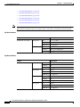
Receive-Queue Limits
Feature
Default Value
2q8t
Low priority: 80%
High priority: 20%
8q4t
Low priority: 80%
Intermediate queues: 0%
High priority: 20%
8q8t
Lowest priority: 80%
Intermediate queues: 0%
Highest priority: 20%
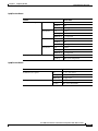
Transmit-Queue Limit s
Feature
Default Value
2q2t
Low priority: 80%
High priority: 20%
1p2q2t
Low priority: 70%
High priority: 15%
Strict priority 15%
1p2q1t
Low priority: 70%
High priority: 15%
Strict priority 15%
1p3q8t
Low priority: 50%
Medium priority: 20%
High priority: 15%
Strict priority 15%
Cisco 7600 Series Router Cisco IOS Software Configuration Guide, Release 12.2SX
42-30
OL-4266-08
Chapter 42
Configuring PFC QoS
PFC QoS Default Configuration
Feature
Default Value
1p7q4t
Standard queue 1 (lowest priority): 50%
Standard queue 2: 20%
Standard queue 3: 15%
Standard queues 4 through 7: 0%
Strict priority 15%
1p7q8t
Standard queue 1 (lowest priority): 50%
Standard queue 2: 20%
Standard queue 3: 15%
Standard queues 4 through 7: 0%
Strict priority 15%
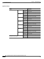
Bandwidth Allocation Ratios
Feature
Default Value
2q8t
90:10
8q4t
90:0:0:0:0:0:0:10
8q8t
90:0:0:0:0:0:0:10
1p3q8t
22:33:45
1p7q4t
100:150:200:0:0:0:0:0
1p7q8t
22:33:45:0:0:0:0
1p2q1t
100:255
2q2t, 1p2q2t, and 1p2q1t
5:255
1p3q1t
100:150:255
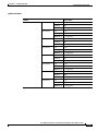
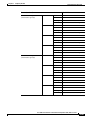
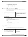
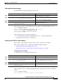
Default Drop-Threshold Percentages and CoS Value Mappings
The following tables list the default drop-thresholds values and CoS mappings for different queue types:
•
1q2t Receive Queues, page 42-32
•
1q4t Receive Queues, page 42-32
•
1p1q4t Receive Queues, page 42-33
•
1p1q0t Receive Queues, page 42-33
•
1p1q8t Receive Queues, page 42-34
•
1q8t Receive Queues, page 42-35
•
2q8t Receive Queues, page 42-36
•
8q4t Receive Queues, page 42-37
•
8q8t Receive Queues, page 42-41
•
2q2t Transmit Queues, page 42-41
Cisco 7600 Series Router Cisco IOS Software Configuration Guide, Release 12.2SX
OL-4266-08
42-31
Chapter 42
Configuring PFC QoS
PFC QoS Default Configuration
Note
•
1p2q2t Transmit Queues, page 42-42
•
1p3q8t Transmit Queues, page 42-43
•
1p7q4t Transmit Queues, page 42-44
•
1p7q8t Transmit Queues, page 42-47
•
1p3q1t Transmit Queues, page 42-48
•
1p2q1t Transmit Queues, page 42-49
The receive queue values shown are the values in effect when the port is configured to trust CoS or DSCP.
When the port is untrusted, the receive queue values are the same as when QoS is globally disabled.
1q2t Receive Queues
Feature
Standard receive queue
Default Value
Threshold 1
CoS
0, 1, 2, 3, and 4
Tail-drop
80%
WRED-drop Not supported
Threshold 2
CoS
5, 6, and 7
Tail-drop
100% (not configurable)
WRED-drop Not supported
1q4t Receive Queues
Feature
Standard receive queue
Default Value
Threshold 1
CoS
0 and 1
Tail-drop
50%
WRED-drop Not supported
Threshold 2
CoS
2 and 3
Tail-drop
60%
WRED-drop Not supported
Threshold 3
CoS
4 and 5
Tail-drop
80%
WRED-drop Not supported
Threshold 4
CoS
6 and 7
Tail-drop
100%
WRED-drop Not supported
Cisco 7600 Series Router Cisco IOS Software Configuration Guide, Release 12.2SX
42-32
OL-4266-08
Chapter 42
Configuring PFC QoS
PFC QoS Default Configuration
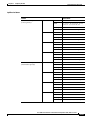
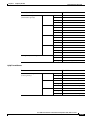
1p1q4t Receive Queues
Feature
Standard receive queue
Default Value
Threshold 1
CoS
0 and 1
Tail-drop
50%
WRED-drop Not supported
Threshold 2
CoS
2 and 3
Tail-drop
60%
WRED-drop Not supported
Threshold 3
CoS
4
Tail-drop
80%
WRED-drop Not supported
Threshold 4
CoS
6 and 7
Tail-drop
100%
WRED-drop Not supported
Strict-priority receive queue
CoS
5
Tail-drop
100% (nonconfigurable)
1p1q0t Receive Queues
Feature
Default Value
Standard receive queue
CoS
0, 1, 2, 3, 4, 6, and 7
Tail-drop
100% (nonconfigurable)
WRED-drop Not supported
Strict-priority receive queue
CoS
5
Tail-drop
100% (nonconfigurable)
Cisco 7600 Series Router Cisco IOS Software Configuration Guide, Release 12.2SX
OL-4266-08
42-33
Chapter 42
Configuring PFC QoS
PFC QoS Default Configuration
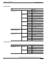
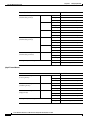
1p1q8t Receive Queues
Feature
Standard receive queue
Default Value
Threshold 1
CoS
0
Tail-drop
Disabled; 70%
WRED-drop Enabled; 40% low, 70% high
Threshold 2
CoS
1
Tail-drop
Disabled; 70%
WRED-drop Enabled; 40% low, 70% high
Threshold 3
CoS
2
Tail-drop
Disabled; 80%
WRED-drop Enabled; 50% low, 80% high
Threshold 4
CoS
3
Tail-drop
Disabled; 80%
WRED-drop Enabled; 50% low, 80% high
Threshold 5
CoS
4
Tail-drop
Disabled; 90%
WRED-drop Enabled; 60% low, 90% high
Threshold 6
CoS
6
Tail-drop
Disabled; 90%
WRED-drop Enabled; 60% low, 90% high
Threshold 7
CoS
7
Tail-drop
Disabled; 100%
WRED-drop Enabled;70% low, 100% high
Strict-priority receive queue
CoS
5
Tail-drop
100% (nonconfigurable)
Cisco 7600 Series Router Cisco IOS Software Configuration Guide, Release 12.2SX
42-34
OL-4266-08
Chapter 42
Configuring PFC QoS
PFC QoS Default Configuration
1q8t Receive Queues
Feature
Standard receive queue
Default Value
Threshold 1
CoS
0
Tail-drop
50%
WRED-drop Not supported
Threshold 2
CoS
None
Tail-drop
50%
WRED-drop Not supported
Threshold 3
CoS
1, 2, 3, 4
Tail-drop
60%
WRED-drop Not supported
Threshold 4
CoS
None
Tail-drop
60%
WRED-drop Not supported
Threshold 5
CoS
6 and 7
Tail-drop
80%
WRED-drop Not supported
Threshold 6
CoS
None
Tail-drop
80%
WRED-drop Not supported
Threshold 7
CoS
5
Tail-drop
100%
WRED-drop Not supported
Threshold 8
CoS
None
Tail-drop
100%
WRED-drop Not supported
Cisco 7600 Series Router Cisco IOS Software Configuration Guide, Release 12.2SX
OL-4266-08
42-35
Chapter 42
Configuring PFC QoS
PFC QoS Default Configuration
2q8t Receive Queues
Feature
Standard receive queue 1
(low priority)
Default Value
Threshold 1
CoS
0 and 1
Tail-drop
70%
WRED-drop Not supported
Threshold 2
CoS
2 and 3
Tail-drop
80%
WRED-drop Not supported
Threshold 3
CoS
4
Tail-drop
90%
WRED-drop Not supported
Threshold 4
CoS
6 and 7
Tail-drop
100%
WRED-drop Not supported
Thresholds 5–8 CoS
Tail-drop
None
100%
WRED-drop Not supported
Standard receive queue 2
(high priority)
Threshold 1
CoS
5
Tail-drop
100%
WRED-drop Not supported
Thresholds 2–8 CoS
Tail-drop
None
100%
WRED-drop Not supported
Cisco 7600 Series Router Cisco IOS Software Configuration Guide, Release 12.2SX
42-36
OL-4266-08
Chapter 42
Configuring PFC QoS
PFC QoS Default Configuration
8q4t Receive Queues
Feature
Standard receive queue 1
(lowest priority)
Default Value
Threshold 1
CoS
0 and 1
DSCP
0–9, 11, 13, 15–17, 19, 21, 23, 25,
27, 29, 31, 33, 39, 41–45, 47
Tail-drop
Disabled; 70%
WRED-drop Enabled; 40% low, 70% high
Threshold 2
CoS
2 and 3
DSCP
Tail-drop
Disabled; 80%
WRED-drop Enabled; 40% low, 80% high
Threshold 3
CoS
4
DSCP
Tail-drop
Disabled; 90%
WRED-drop Enabled; 50% low, 90% high
Threshold 4
CoS
6 and 7
DSCP
Tail-drop
Disabled; 100%
WRED-drop Enabled; 50% low, 100% high
Standard receive queue 2
(intermediate priority)
Threshold 1
CoS
None
DSCP
14
Tail-drop
Enabled; 100%
WRED-drop Disabled; 100% low, 100% high
Threshold 2
CoS
None
DSCP
12
Tail-drop
Enabled; 100%
WRED-drop Disabled; 100% low, 100% high
Threshold 3
CoS
None
DSCP
10
Tail-drop
Enabled; 100%
WRED-drop Disabled; 100% low, 100% high
Threshold 4
CoS
None
DSCP
None
Tail-drop
Enabled; 100%
WRED-drop Disabled; 100% low, 100% high
Cisco 7600 Series Router Cisco IOS Software Configuration Guide, Release 12.2SX
OL-4266-08
42-37
Chapter 42
Configuring PFC QoS
PFC QoS Default Configuration
Feature (continued)
Standard receive queue 3
(intermediate priority)
Default Value
Threshold 1
CoS
None
DSCP
22
Tail-drop
Enabled; 100%
WRED-drop Disabled; 100% low, 100% high
Threshold 2
CoS
None
DSCP
20
Tail-drop
Enabled; 100%
WRED-drop Disabled; 100% low, 100% high
Threshold 3
CoS
None
DSCP
18
Tail-drop
Enabled; 100%
WRED-drop Disabled; 100% low, 100% high
Threshold 4
CoS
None
DSCP
None
Tail-drop
Enabled; 100%
WRED-drop Disabled; 100% low, 100% high
Standard receive queue 4
(intermediate priority)
Threshold 1
CoS
None
DSCP
24 and 30
Tail-drop
Enabled; 100%
WRED-drop Disabled; 100% low, 100% high
Threshold 2
CoS
None
DSCP
28
Tail-drop
Enabled; 100%
WRED-drop Disabled; 100% low, 100% high
Threshold 3
CoS
None
DSCP
26
Tail-drop
Enabled; 100%
WRED-drop Disabled; 100% low, 100% high
Threshold 4
CoS
None
DSCP
None
Tail-drop
Enabled; 100%
WRED-drop Disabled; 100% low, 100% high
Cisco 7600 Series Router Cisco IOS Software Configuration Guide, Release 12.2SX
42-38
OL-4266-08
Chapter 42
Configuring PFC QoS
PFC QoS Default Configuration
Feature (continued)
Standard receive queue 5
(intermediate priority)
Default Value
Threshold 1
CoS
None
DSCP
32, 34–38
Tail-drop
Enabled; 100%
WRED-drop Disabled; 100% low, 100% high
Threshold 2
CoS
None
DSCP
None
Tail-drop
Enabled; 100%
WRED-drop Disabled; 100% low, 100% high
Threshold 3
CoS
None
DSCP
None
Tail-drop
Enabled; 100%
WRED-drop Disabled; 100% low, 100% high
Threshold 4
CoS
None
DSCP
None
Tail-drop
Enabled; 100%
WRED-drop Disabled; 100% low, 100% high
Standard receive queue 6
(intermediate priority)
Threshold 1
CoS
None
DSCP
48–63
Tail-drop
Enabled; 100%
WRED-drop Disabled; 100% low, 100% high
Threshold 2
CoS
None
DSCP
None
Tail-drop
Enabled; 100%
WRED-drop Disabled; 100% low, 100% high
Threshold 3
CoS
None
DSCP
None
Tail-drop
Enabled; 100%
WRED-drop Disabled; 100% low, 100% high
Threshold 4
CoS
None
DSCP
None
Tail-drop
Enabled; 100%
WRED-drop Disabled; 100% low, 100% high
Cisco 7600 Series Router Cisco IOS Software Configuration Guide, Release 12.2SX
OL-4266-08
42-39
Chapter 42
Configuring PFC QoS
PFC QoS Default Configuration
Feature (continued)
Standard receive queue 7
(intermediate priority)
Default Value
Threshold 1
CoS
None
DSCP
None
Tail-drop
Enabled; 100%
WRED-drop Disabled; 100% low, 100% high
Threshold 2
CoS
None
DSCP
None
Tail-drop
Enabled; 100%
WRED-drop Disabled; 100% low, 100% high
Threshold 3
CoS
None
DSCP
None
Tail-drop
Enabled; 100%
WRED-drop Disabled; 100% low, 100% high
Threshold 4
CoS
None
DSCP
None
Tail-drop
Enabled; 100%
WRED-drop Disabled; 100% low, 100% high
Standard receive queue 8
(high priority)
Threshold 1
CoS
5
DSCP
40 and 46
Tail-drop
Enabled; 100%
WRED-drop Disabled; 100% low, 100% high
Threshold 2
CoS
None
DSCP
None
Tail-drop
Enabled; 100%
WRED-drop Disabled; 100% low, 100% high
Threshold 3
CoS
None
DSCP
None
Tail-drop
Enabled; 100%
WRED-drop Disabled; 100% low, 100% high
Threshold 4
CoS
None
DSCP
None
Tail-drop
Enabled; 100%
WRED-drop Disabled; 100% low, 100% high
Cisco 7600 Series Router Cisco IOS Software Configuration Guide, Release 12.2SX
42-40
OL-4266-08
Chapter 42
Configuring PFC QoS
PFC QoS Default Configuration
8q8t Receive Queues
Feature
Default Value
Standard receive queue 1
(lowest priority)
Threshold 1
CoS
0 and 1
Tail-drop
Disabled; 70%
WRED-drop Enabled; 40% low, 70% high
Threshold 2
CoS
2 and 3
Tail-drop
Disabled; 80%
WRED-drop Enabled; 40% low, 80% high
Threshold 3
CoS
4
Tail-drop
Disabled; 90%
WRED-drop Enabled; 50% low, 90% high
Threshold 4
CoS
6 and 7
Tail-drop
Disabled; 100%
WRED-drop Enabled; 50% low, 100% high
Thresholds 5–8 CoS
Tail-drop
None
Disabled; 100%
WRED-drop Enabled; 50% low, 100% high
Standard receive queues 2–7
(intermediate priorities)
Thresholds 1–8 CoS
Tail-drop
None
Enabled; 100%
WRED-drop Disabled; 100% low, 100% high
Standard receive queue 8
(highest priority)
Threshold 1
CoS
5
Tail-drop
Enabled; 100%
WRED-drop Disabled; 100% low, 100% high
Thresholds 2–8 CoS
Tail-drop
None
Enabled; 100%
WRED-drop Disabled; 100% low, 100% high
2q2t Transmit Queues
Feature
Default Value
Standard transmit queue 1
(low priority)
Threshold 1
CoS
0 and 1
Tail-drop
80%
WRED-drop Not supported
Threshold 2
CoS
2 and 3
Tail-drop
100%
WRED-drop Not supported
Cisco 7600 Series Router Cisco IOS Software Configuration Guide, Release 12.2SX
OL-4266-08
42-41
Chapter 42
Configuring PFC QoS
PFC QoS Default Configuration
Feature
Standard transmit queue 2
(high priority)
Default Value
Threshold 1
CoS
4 and 5
Tail-drop
80%
WRED-drop Not supported
Threshold 2
CoS
6 and 7
Tail-drop
100%
WRED-drop Not supported
1p2q2t Transmit Queues
Feature
Standard transmit queue 1
(low priority)
Default Value
Threshold 1
CoS
0 and 1
Tail-drop
Not supported
WRED-drop 40% low, 70% high
Threshold 2
CoS
2 and 3
Tail-drop
Not supported
WRED-drop 70% low, 100% high
Standard transmit queue 2
(high priority)
Threshold 1
CoS
4 and 6
Tail-drop
Not supported
WRED-drop 40% low, 70% high
Threshold 2
CoS
7
Tail-drop
Not supported
WRED-drop 70% low, 100% high
Strict-priority transmit queue
CoS
5
Tail-drop
100% (nonconfigurable)
Cisco 7600 Series Router Cisco IOS Software Configuration Guide, Release 12.2SX
42-42
OL-4266-08
Chapter 42
Configuring PFC QoS
PFC QoS Default Configuration
1p3q8t Transmit Queues
Feature
Default Value
Standard transmit queue 1
(lowest priority)
Threshold 1
CoS
0
Tail-drop
Disabled; 70%
WRED-drop Enabled; 40% low, 70% high
Threshold 2
CoS
1
Tail-drop
Disabled; 100%
WRED-drop Enabled; 70% low, 100% high
Threshold 3
CoS
None
Tail-drop
Disabled; 100%
WRED-drop Enabled; 70% low, 100% high
Threshold 4
CoS
None
Tail-drop
Disabled; 100%
WRED-drop Enabled; 70% low, 100% high
Thresholds 5–8 CoS
Tail-drop
None
Disabled; 100%
WRED-drop Enabled; 50% low, 100% high
Standard transmit queue 2
(medium priority)
Threshold 1
CoS
2
Tail-drop
Disabled; 70%
WRED-drop Enabled; 40% low, 70% high
Threshold 2
CoS
3 and 4
Tail-drop
Disabled; 100%
WRED-drop Enabled; 70% low, 100% high
Thresholds 3–8 CoS
Tail-drop
None
Disabled; 100%
WRED-drop Enabled; 70% low, 100% high
Standard transmit queue 3
(high priority)
Threshold 1
CoS
6 and 7
Tail-drop
Disabled; 100%
WRED-drop Enabled; 70% low, 100% high
Thresholds 2–8 CoS
Tail-drop
None
Disabled; 100%
WRED-drop Enabled; 70% low, 100% high
Strict-priority transmit queue
CoS
5
Tail-drop
100% (nonconfigurable)
Cisco 7600 Series Router Cisco IOS Software Configuration Guide, Release 12.2SX
OL-4266-08
42-43
Chapter 42
Configuring PFC QoS
PFC QoS Default Configuration
1p7q4t Transmit Queues
Feature
Standard receive queue 1
(lowest priority)
Default Value
Threshold 1
CoS
0 and 1
DSCP
0–9, 11, 13, 15–17, 19, 21, 23, 25,
27, 29, 31, 33, 39, 41–45, 47
Tail-drop
Disabled; 70%
WRED-drop Enabled; 40% low, 70% high
Threshold 2
CoS
2 and 3
DSCP
Tail-drop
Disabled; 100%
WRED-drop Enabled; 70% low, 100% high
Threshold 3
CoS
4
DSCP
Tail-drop
Disabled; 100%
WRED-drop Enabled; 70% low, 100% high
Threshold 4
CoS
6 and 7
DSCP
Tail-drop
Disabled; 100%
WRED-drop Enabled; 70% low, 100% high
Standard receive queue 2
(intermediate priority)
Threshold 1
CoS
None
DSCP
14
Tail-drop
Disabled; 70%
WRED-drop Enabled; 40% low, 70% high
Threshold 2
CoS
None
DSCP
12
Tail-drop
Disabled; 100%
WRED-drop Enabled; 70% low, 100% high
Threshold 3
CoS
None
DSCP
10
Tail-drop
Disabled; 100%
WRED-drop Enabled; 70% low, 100% high
Threshold 4
CoS
None
DSCP
None
Tail-drop
Disabled; 100%
WRED-drop Enabled; 70% low, 100% high
Cisco 7600 Series Router Cisco IOS Software Configuration Guide, Release 12.2SX
42-44
OL-4266-08
Chapter 42
Configuring PFC QoS
PFC QoS Default Configuration
Feature (continued)
Standard receive queue 3
(intermediate priority)
Default Value
Threshold 1
CoS
None
DSCP
22
Tail-drop
Disabled; 100%
WRED-drop Enabled; 70% low, 100% high
Threshold 2
CoS
None
DSCP
20
Tail-drop
Disabled; 100%
WRED-drop Enabled; 70% low, 100% high
Threshold 3
CoS
None
DSCP
18
Tail-drop
Disabled; 100%
WRED-drop Enabled; 70% low, 100% high
Threshold 4
CoS
None
DSCP
None
Tail-drop
Disabled; 100%
WRED-drop Enabled; 70% low, 100% high
Standard receive queue 4
(intermediate priority)
Threshold 1
CoS
None
DSCP
24 and 30
Tail-drop
Enabled; 100%
WRED-drop Disabled; 100% low, 100% high
Threshold 2
CoS
None
DSCP
28
Tail-drop
Enabled; 100%
WRED-drop Disabled; 100% low, 100% high
Threshold 3
CoS
None
DSCP
26
Tail-drop
Enabled; 100%
WRED-drop Disabled; 100% low, 100% high
Threshold 4
CoS
None
DSCP
None
Tail-drop
Enabled; 100%
WRED-drop Disabled; 100% low, 100% high
Cisco 7600 Series Router Cisco IOS Software Configuration Guide, Release 12.2SX
OL-4266-08
42-45
Chapter 42
Configuring PFC QoS
PFC QoS Default Configuration
Feature (continued)
Standard receive queue 5
(intermediate priority)
Default Value
Threshold 1
CoS
None
DSCP
32, 34–38
Tail-drop
Enabled; 100%
WRED-drop Disabled; 100% low, 100% high
Threshold 2
CoS
None
DSCP
None
Tail-drop
Enabled; 100%
WRED-drop Disabled; 100% low, 100% high
Threshold 3
CoS
None
DSCP
None
Tail-drop
Enabled; 100%
WRED-drop Disabled; 100% low, 100% high
Threshold 4
CoS
None
DSCP
None
Tail-drop
Enabled; 100%
WRED-drop Disabled; 100% low, 100% high
Standard receive queue 6
(intermediate priority)
Threshold 1
CoS
None
DSCP
48–63
Tail-drop
Enabled; 100%
WRED-drop Disabled; 100% low, 100% high
Threshold 2
CoS
None
DSCP
None
Tail-drop
Enabled; 100%
WRED-drop Disabled; 100% low, 100% high
Threshold 3
CoS
None
DSCP
None
Tail-drop
Enabled; 100%
WRED-drop Disabled; 100% low, 100% high
Threshold 4
CoS
None
DSCP
None
Tail-drop
Enabled; 100%
WRED-drop Disabled; 100% low, 100% high
Cisco 7600 Series Router Cisco IOS Software Configuration Guide, Release 12.2SX
42-46
OL-4266-08
Chapter 42
Configuring PFC QoS
PFC QoS Default Configuration
Feature (continued)
Default Value
Standard receive queue 7
(intermediate priority)
Threshold 1
CoS
None
DSCP
None
Tail-drop
Enabled; 100%
WRED-drop Disabled; 100% low, 100% high
Threshold 2
CoS
None
DSCP
None
Tail-drop
Enabled; 100%
WRED-drop Disabled; 100% low, 100% high
Threshold 3
CoS
None
DSCP
None
Tail-drop
Enabled; 100%
WRED-drop Disabled; 100% low, 100% high
Threshold 4
CoS
None
DSCP
None
Tail-drop
Enabled; 100%
WRED-drop Disabled; 100% low, 100% high
Strict-priority transmit queue
CoS
5
DSCP
40 and 46
Tail-drop
100% (nonconfigurable)
1p7q8t Transmit Queues
Feature
Default Value
Standard transmit queue 1
(lowest priority)
Threshold 1
CoS
0
Tail-drop
Disabled; 70%
WRED-drop Enabled; 40% low, 70% high
Threshold 2
CoS
1
Tail-drop
Disabled; 100%
WRED-drop Enabled; 70% low, 100% high
Thresholds 3–8 CoS
Tail-drop
None
Disabled; 100%
WRED-drop Enabled; 70% low, 100% high
Cisco 7600 Series Router Cisco IOS Software Configuration Guide, Release 12.2SX
OL-4266-08
42-47
Chapter 42
Configuring PFC QoS
PFC QoS Default Configuration
Feature (continued)
Standard transmit queue 2
(intermediate priority)
Default Value
Threshold 1
CoS
2
Tail-drop
Disabled; 70%
WRED-drop Enabled; 40% low, 70% high
Threshold 2
CoS
3 and 4
Tail-drop
Disabled; 100%
WRED-drop Enabled; 70% low, 100% high
Thresholds 3–8 CoS
Tail-drop
None
Disabled; 100%
WRED-drop Enabled; 70% low, 100% high
Standard transmit queue 3
(intermediate priority)
Threshold 1
CoS
6 and 7
Tail-drop
Disabled; 100%
WRED-drop Enabled; 70% low, 100% high
Thresholds 2–8 CoS
Tail-drop
None
Disabled; 100%
WRED-drop Enabled; 100% low, 100% high
Standard transmit queues 4–7
(intermediate priorities)
Thresholds 1–8 CoS
Tail-drop
None
Disabled; 100%
WRED-drop Enabled; 100% low, 100% high
Strict-priority transmit queue
CoS
5
Tail-drop
100% (nonconfigurable)
1p3q1t Transmit Queues
Feature
Standard transmit queue 1
(lowest priority)
Default Value
Threshold 1
CoS
0 and 1
Tail-drop
Disabled; 100%
WRED-drop Enabled; 70% low, 100% high
Standard transmit queue 2
(medium priority)
Threshold 1
CoS
2, 3, and 4
Tail-drop
Disabled; 100%
WRED-drop Enabled; 70% low, 100% high
Standard transmit queue 3
(high priority)
Threshold 1
CoS
6 and 7
Tail-drop
Disabled; 100%
WRED-drop Enabled; 70% low, 100% high
Strict-priority transmit queue
CoS
5
Tail-drop
100% (nonconfigurable)
Cisco 7600 Series Router Cisco IOS Software Configuration Guide, Release 12.2SX
42-48
OL-4266-08
Chapter 42
Configuring PFC QoS
PFC QoS Configuration Guidelines and Restrictions
1p2q1t Transmit Queues
Feature
Default Value
Standard transmit queue 1
(lowest priority)
Threshold 1
CoS
0, 1, 2, and 3
Tail-drop
Not supported
WRED-drop Enabled; 70% low, 100% high
Standard transmit queue 3
(high priority)
Threshold 1
CoS
4, 6, and 7
Tail-drop
Not supported
WRED-drop Enabled; 70% low, 100% high
Strict-priority transmit queue
CoS
5
Tail-drop
100% (nonconfigurable)
Default Values With PFC QoS Disabled
Feature
Default Value
Ingress LAN port trust state
trust DSCP.
Receive-queue drop-threshold percentages
All thresholds set to 100%.
Transmit-queue drop-threshold percentages
All thresholds set to 100%.
Transmit-queue bandwidth allocation ratio
255:1.
Transmit-queue size ratio
Low priority: 100% (other queues not used).
CoS value and drop threshold mapping
All QoS labels mapped to the low-priority queue.
PFC QoS Configuration Guidelines and Restrictions
When configuring PFC QoS, follow these guidelines and restrictions:
•
General Guidelines, page 42-50
•
PFC3 Guidelines, page 42-51
•
PFC2 Guidelines, page 42-52
•
Class Map Command Restrictions, page 42-53
•
Policy Map Command Restrictions, page 42-53
•
Policy Map Class Command Restrictions, page 42-53
•
Supported Granularity for CIR and PIR Rate Values, page 42-53
•
Supported Granularity for CIR and PIR Token Bucket Sizes, page 42-54
•
IP Precedence and DSCP Values, page 42-55
Cisco 7600 Series Router Cisco IOS Software Configuration Guide, Release 12.2SX
OL-4266-08
42-49
Chapter 42
Configuring PFC QoS
PFC QoS Configuration Guidelines and Restrictions
General Guidelines
•
The match ip precedence and match ip dscp commands filter only IPv4 traffic.
•
In Release 12.2(18)SXE and later releases, the match precedence and match dscp commands filter
IPv4 and IPv6 traffic.
•
In Release 12.2(18)SXE and later releases, the set ip dscp and set ip precedence commands are
saved in the configuration file as set dscp and set precedence commands.
•
In Release 12.2(18)SXE and later releases, PFC QoS supports the set dscp and set precedence
policy map class commands for IPv4 and IPv6 traffic.
•
The flowmask requirements of QoS, NetFlow, and NetFlow data export (NDE) might conflict,
especially if you configure microflow policing.
•
With egress ACL support for remarked DSCP and VACL capture both configured on an interface,
VACL capture might capture two copies of each packet, and the second copy might be corrupt.
•
You cannot configure egress ACL support for remarked DSCP on tunnel interfaces.
•
Egress ACL support for remarked DSCP supports IP unicast traffic.
•
Egress ACL support for remarked DSCP is not relevant to multicast traffic. PFC QoS applies ingress
QoS changes to multicast traffic before applying egress QoS.
•
NetFlow and NetFlow data export (NDE) do not support interfaces where egress ACL support for
remarked DSCP is configured.
•
When egress ACL support for remarked DSCP is configured on any interface, you must configure
an interface-specific flowmask to enable NetFlow and NDE support on interfaces where egress ACL
support for remarked DSCP is not configured. Enter either the mls flow ip
interface-destination-source or the mls flow ip interface-full global configuration mode
command.
•
Interface counters are not accurate on interfaces where egress ACL support for remarked DSCP is
configured.
•
You cannot apply microflow policing to IPv6 multicast traffic.
•
You cannot apply microflow policing to traffic that has been permitted by egress ACL support for
remarked DSCP.
•
Traffic that has been permitted by egress ACL support for remarked DSCP cannot be tagged as
MPLS traffic. (The traffic can be tagged as MPLS traffic on another network device.)
•
When you apply both ingress policing and egress policing to the same traffic, both the input policy
and the output policy must either mark down traffic or drop traffic. PFC QoS does not support
ingress markdown with egress drop or ingress drop with egress markdown. (CSCea23571)
•
If traffic is both aggregate and microflow policed, then the aggregate and microflow policers must
both be in the same policy-map class and each must use the same conform-action and
exceed-action keyword option: drop, set-dscp-transmit, set-prec-transmit, or transmit.
•
You cannot configure PFC QoS features on tunnel interfaces.
•
PFC QoS does not rewrite the payload ToS byte in tunnel traffic.
•
PFC QoS filters only by ACLs, dscp values, or IP precedence values.
Cisco 7600 Series Router Cisco IOS Software Configuration Guide, Release 12.2SX
42-50
OL-4266-08
Chapter 42
Configuring PFC QoS
PFC QoS Configuration Guidelines and Restrictions
•
For these commands, PFC QoS applies identical configuration to all LAN ports controlled by the
same application-specific integrated circuit (ASIC):
– rcv-queue random-detect
– rcv-queue queue-limit
– wrr-queue queue-limit
– wrr-queue bandwidth (except Gigabit Ethernet LAN ports)
– priority-queue cos-map
– rcv-queue cos-map
– wrr-queue cos-map
– wrr-queue threshold
– rcv-queue threshold
– wrr-queue random-detect
– wrr-queue random-detect min-threshold
– wrr-queue random-detect max-threshold
•
Configure these commands only on physical ports. Do not configure these commands on logical
interfaces:
– priority-queue cos-map
– wrr-queue cos-map
– wrr-queue random-detect
– wrr-queue random-detect max-threshold
– wrr-queue random-detect min-threshold
– wrr-queue threshold
– wrr-queue queue-limit
– wrr-queue bandwidth
– rcv-queue cos-map
– rcv-queue bandwidth
– rcv-queue random-detect
– rcv-queue random-detect max-threshold
– rcv-queue random-detect min-threshold
– rcv-queue queue-limit
– rcv-queue cos-map
– rcv-queue threshold
PFC3 Guidelines
•
With Release 12.2(18)SXE and later releases, all versions of the PFC3 support QoS for IPv6 unicast
and multicast traffic.
•
To display information about IPv6 PFC QoS, enter the show mls qos ipv6 command.
Cisco 7600 Series Router Cisco IOS Software Configuration Guide, Release 12.2SX
OL-4266-08
42-51
Chapter 42
Configuring PFC QoS
PFC QoS Configuration Guidelines and Restrictions
•
The QoS features implemented in the port ASICs (queue architecture and dequeuing algorithms)
support IPv4 and IPv6 traffic.
•
The PFC3 supports IPv6 named extended ACLs and named standard ACLs.
•
In Release 12.2(18)SXE and later releases, the PFC3 supports the match protocol ipv6 command.
•
Because of conflicting TCAM lookup flow key bit requirements, you cannot configure IPv6
DSCP-based filtering and IPv6 Layer 4 range-based filtering on the same interface. For example:
– If you configure both a DSCP value and a Layer 4 “greater than” (gt) or “less than” (lt) operator
in an IPv6 ACE, you cannot use the ACL for PFC QoS filtering.
– If you configure a DSCP value in one IPv6 ACL and a Layer 4 “greater than” (gt) or “less than”
(lt) operator in another IPv6 ACL, you cannot use both ACLs in different class maps on the same
interface for PFC QoS filtering.
•
In Release 12.2(18)SXE and later releases, you can apply aggregate and microflow policers to IPv6
traffic, but you cannot apply microflow policing to IPv6 multicast traffic.
•
With egress ACL support for remarked DSCP configured, the PFC3 does not provide
hardware-assistance for these features:
– Cisco IOS reflexive ACLs
– TCP intercept
– Context-Based Access Control (CBAC)
– Network Address Translation (NAT)
•
With a PFC3, you cannot apply microflow policing to ARP traffic.
•
The PFC3 does not apply egress policing to traffic that is being bridged to the MSFC3.
•
The PFC3 does not apply egress policing or egress DSCP mutation to multicast traffic from the
MSFC3.
•
With a PFC3, PFC QoS does not rewrite the ToS byte in bridged multicast traffic.
PFC2 Guidelines
•
The PFC2 supports the match protocol class map command, which configures NBAR and sends all
traffic on the Layer 3 interface, both ingress and egress, to be processed in software on the MSFC2.
To configure NBAR, refer to this publication:
http://www.cisco.com/univercd/cc/td/doc/product/software/ios122/122newft/122t/122t8/dtnbarad.htm
•
The PFC2 does not support these PFC QoS features:
– Egress policing
– Egress DSCP mutation
– DSCP Transparency
– VLAN-based QoS with DFCs installed
•
The PFC2 does not support the modules that support ingress CoS mutation on IEEE 802.1Q tunnel
ports.
Cisco 7600 Series Router Cisco IOS Software Configuration Guide, Release 12.2SX
42-52
OL-4266-08
Chapter 42
Configuring PFC QoS
PFC QoS Configuration Guidelines and Restrictions
Class Map Command Restrictions
•
With Release 12.2(18)SXE and later releases, PFC QoS supports the match any class map
command.
•
PFC QoS supports class maps that contain a single match command.
•
PFC QoS does not support these class map commands:
– match cos
– match any
– match classmap
– match destination-address
– match input-interface
– match qos-group
– match source-address
Policy Map Command Restrictions
PFC QoS does not support these policy map commands:
•
class class_name destination-address
•
class class_name input-interface
•
class class_name protocol
•
class class_name qos-group
•
class class_name source-address
Policy Map Class Command Restrictions
PFC QoS does not support these policy map class commands:
•
bandwidth
•
priority
•
queue-limit
•
random-detect
•
set qos-group
•
service-policy
Supported Granularity for CIR and PIR Rate Values
PFC QoS has the following hardware granularity for CIR and PIR rate values:
CIR and PIR Rate Value Range
Granularity
32768 to 2097152 (2 Mbs)
32768 (32 Kb)
2097153 to 4194304 (4 Mbs)
65536 (64 Kb)
Cisco 7600 Series Router Cisco IOS Software Configuration Guide, Release 12.2SX
OL-4266-08
42-53
Chapter 42
Configuring PFC QoS
PFC QoS Configuration Guidelines and Restrictions
CIR and PIR Rate Value Range
Granularity
4194305 to 8388608 (8 Mbs)
131072 (128 Kb)
8388609 to 16777216 (16 Mbs)
262144 (256 Kb)
16777217 to 33554432 (32 Mbs)
524288 (512 Kb)
33554433 to 67108864 (64 Mbs)
1048576 (1 Mb)
67108865 to 134217728 (128 Mbs)
2097152 (2 Mb)
134217729 to 268435456 (256 Mbs)
4194304 (4 Mb)
268435457 to 536870912 (512 Mbs)
8388608 (8 Mb)
536870913 to 1073741824 (1 Gps)
16777216 (16 Mb)
1073741825 to 2147483648 (2 Gps)
33554432 (32 Mb)
2147483649 to 4294967296 (4 Gps)
67108864 (64 Mb)
4294967296 to 8589934592 (8 Gps)
134217728 (128 Mb)
8589934592 to 10000000000 (10 Gps) 268435456 (256 Mb)
Within each range, PFC QoS programs the PFC with rate values that are multiples of the granularity
values.
Supported Granularity for CIR and PIR Token Bucket Sizes
PFC QoS has the following hardware granularity for CIR and PIR token bucket (burst) sizes:
CIR and PIR Token Bucket Size Range Granularity
1 to 32768 (32 KB)
1024 (1 KB)
32769 to 65536 (64 KB)
2048 (2 KB)
65537 to 131072 (128 KB)
4096 (4 KB)
131073 to 262144 (256 KB)
8196 (8 KB)
262145 to 524288 (512 KB)
16392 (16 KB)
524289 to 1048576 (1 MB)
32768 (32 KB)
1048577 to 2097152 (2 MB)
65536 (64 KB)
2097153 to 4194304 (4 MB)
131072 (128 KB)
4194305 to 8388608 (8 MB)
262144 (256 KB)
8388609 to 16777216 (16 MB)
524288 (512 KB)
16777217 to 33554432 (32 MB)
1048576 (1 MB)
Within each range, PFC QoS programs the PFC with token bucket sizes that are multiples of the
granularity values.
Cisco 7600 Series Router Cisco IOS Software Configuration Guide, Release 12.2SX
42-54
OL-4266-08
Chapter 42
Configuring PFC QoS
Configuring PFC QoS
IP Precedence and DSCP Values
3-bit IP
Precedence
6 MSb1 of ToS
0
0
0
0
0
0
0
0
0
0
0
0
0
0
0
0
0
0
0
0
0
0
0
0
0
0
0
0
0
1
1
1
1
0
0
1
1
0
0
1
1
0
1
0
1
0
1
0
1
1
0
0
0
0
0
0
0
0
0
0
0
0
0
0
0
0
1
1
1
1
1
1
1
1
0
0
0
0
1
1
1
1
0
0
1
1
0
0
1
1
2
0
0
0
0
0
0
0
0
1
1
1
1
1
1
1
1
0
0
0
0
0
0
0
0
0
0
0
0
1
1
1
1
3
0
0
0
0
0
0
0
0
1
1
1
1
1
1
1
1
1
1
1
1
1
1
1
1
0
0
0
0
1
1
1
1
8 7 6
3-bit IP
Precedence
6 MSb1 of ToS
0
1
2
3
4
5
6
7
4
1
1
1
1
1
1
1
1
0
0
0
0
0
0
0
0
0
0
0
0
0
0
0
0
0
0
0
0
1
1
1
1
0
0
1
1
0
0
1
1
0
1
0
1
0
1
0
1
32
33
34
35
36
37
38
39
0
1
0
1
0
1
0
1
8
9
10
11
12
13
14
15
5
1
1
1
1
1
1
1
1
0
0
0
0
0
0
0
0
1
1
1
1
1
1
1
1
0
0
0
0
1
1
1
1
0
0
1
1
0
0
1
1
0
1
0
1
0
1
0
1
40
41
42
43
44
45
46
47
0
0
1
1
0
0
1
1
0
1
0
1
0
1
0
1
16
17
18
19
20
21
22
23
6
1
1
1
1
1
1
1
1
1
1
1
1
1
1
1
1
0
0
0
0
0
0
0
0
0
0
0
0
1
1
1
1
0
0
1
1
0
0
1
1
0
1
0
1
0
1
0
1
48
49
50
51
52
53
54
55
0
0
1
1
0
0
1
1
0
1
0
1
0
1
0
1
24
25
26
27
28
29
30
31
7
1
1
1
1
1
1
1
1
1
1
1
1
1
1
1
1
1
1
1
1
1
1
1
1
0
0
0
0
1
1
1
1
0
0
1
1
0
0
1
1
0
1
0
1
0
1
0
1
56
57
58
59
60
61
62
63
6-bit
5 4 3 DSCP
8 7 6
6-bit
DSCP
5 4 3
1. MSb = most significant bit
Configuring PFC QoS
These sections describe how to configure PFC QoS on the Cisco 7600 series routers:
•
Enabling PFC QoS Globally, page 42-56
•
Enabling Ignore Port Trust, page 42-57
•
Configuring DSCP Transparency, page 42-58
•
Enabling Queueing-Only Mode, page 42-58
Cisco 7600 Series Router Cisco IOS Software Configuration Guide, Release 12.2SX
OL-4266-08
42-55
Chapter 42
Configuring PFC QoS
Configuring PFC QoS
Note
•
Enabling Microflow Policing of Bridged Traffic, page 42-59
•
Enabling VLAN-Based PFC QoS on Layer 2 LAN Ports, page 42-60
•
Enabling Egress ACL Support for Remarked DSCP, page 42-61
•
Creating Named Aggregate Policers, page 42-61
•
Configuring a PFC QoS Policy, page 42-64
•
Configuring Egress DSCP Mutation on a PFC3, page 42-82
•
Configuring Ingress CoS Mutation on IEEE 802.1Q Tunnel Ports, page 42-83
•
Configuring DSCP Value Maps, page 42-86
•
Configuring the Trust State of Ethernet LAN and OSM Ports, page 42-90
•
Configuring the Ingress LAN Port CoS Value, page 42-91
•
Configuring Standard-Queue Drop Threshold Percentages, page 42-92
•
Mapping QoS Labels to Queues and Drop Thresholds, page 42-98
•
Allocating Bandwidth Between Standard Transmit Queues, page 42-108
•
Setting the Receive-Queue Size Ratio, page 42-110
•
Configuring the Transmit-Queue Size Ratio, page 42-111
PFC QoS processes both unicast and multicast traffic.
Enabling PFC QoS Globally
To enable PFC QoS globally, perform this task:
Command
Purpose
Router(config)# mls qos
Enables PFC QoS globally on the router.
Router(config)# no mls qos
Disables PFC QoS globally on the router.
Step 2
Router(config)# end
Exits configuration mode.
Step 3
Router# show mls qos [ipv6]
Verifies the configuration.
Step 1
This example shows how to enable PFC QoS globally:
Router# configure terminal
Router(config)# mls qos
Router(config)# end
Router#
This example shows how to verify the configuration:
Router# show mls qos
QoS is enabled globally
Microflow QoS is enabled globally
QoS global counters:
Total packets: 544393
IP shortcut packets: 1410
Packets dropped by policing: 0
IP packets with TOS changed by policing: 467
Cisco 7600 Series Router Cisco IOS Software Configuration Guide, Release 12.2SX
42-56
OL-4266-08
Chapter 42
Configuring PFC QoS
Configuring PFC QoS
IP packets with COS changed by policing: 59998
Non-IP packets with COS changed by policing: 0
Router#
Enabling Ignore Port Trust
In Release 12.2(18)SXF5 and later releases, the ignore port trust feature allows an ingress policy to
apply a configured IP precedence or DSCP value to any traffic, rather than only to untrusted traffic.
To enable ignore port trust, perform this task:
Command
Purpose
Router(config)# mls qos marking ignore port-trust
Enables ignore port trust globally on the router.
Router(config)# no mls qos marking ignore port-trust
Disables ignore port trust globally on the router
(default).
Step 2
Router(config)# end
Exits configuration mode.
Step 3
Router# show mls qos | include ignores
Verifies the configuration.
Step 1
Note
For untrusted traffic, when ignore port trust is enabled, PFC QoS does the following:
•
For IP traffic, PFC QoS uses the received DSCP value as the initial internal DSCP value.
•
For traffic without a recognizable ToS byte, PFC QoS maps the port CoS value to the initial internal
DSCP value.
This example shows how to enable ignore port trust and verify the configuration:
Router# configure terminal
Router(config)# mls qos marking ignore port-trust
Router(config)# end
Router# show mls qos | include ignores
Policy marking ignores port_trust
Router#
Cisco 7600 Series Router Cisco IOS Software Configuration Guide, Release 12.2SX
OL-4266-08
42-57
Chapter 42
Configuring PFC QoS
Configuring PFC QoS
Configuring DSCP Transparency
Note
•
In addition to support for other IP traffic, the PFC3B and PFC3BXL support the no mls qos rewrite
ip dscp command for MPLS traffic, traffic in IP in IP tunnels, and traffic in GRE tunnels.
•
The PFC3A supports the no mls qos rewrite ip dscp command for all IP traffic except MPLS traffic,
traffic in IP in IP tunnels, and traffic in GRE tunnels.
To enable DSCP transparency, which preserves the received Layer 3 ToS byte, perform this task:
Command
Purpose
Router(config)# no mls qos rewrite ip dscp
Disables egress ToS-byte rewrite globally on the router.
Router(config)# mls qos rewrite ip dscp
Enables egress ToS-byte rewrite globally on the router.
Step 2
Router(config)# end
Exits configuration mode.
Step 3
Router# show mls qos | include rewrite
Verifies the configuration.
Step 1
When you preserve the received Layer 3 ToS byte, QoS uses the marked or marked-down CoS value for
egress queueing and in egress tagged traffic.
This example shows how to preserve the received Layer 3 ToS byte and verify the configuration:
Router# configure terminal
Router(config)# no mls qos rewrite ip dscp
Router(config)# end
Router# show mls qos | include rewrite
QoS ip packet dscp rewrite disabled globally
Router#
Enabling Queueing-Only Mode
To enable queueing-only mode on the router, perform this task:
Step 1
Command
Purpose
Router(config)# mls qos queueing-only
Enables queueing-only mode on the router.
Router(config)# no mls qos queueing-only
Disables PFC QoS globally on the router.
Note
You cannot disable queueing-only mode
separately.
Step 2
Router(config)# end
Exits configuration mode.
Step 3
Router# show mls qos
Verifies the configuration.
When you enable queueing-only mode, the router does the following:
•
Disables marking and policing globally
•
Configures all ports to trust Layer 2 CoS
Cisco 7600 Series Router Cisco IOS Software Configuration Guide, Release 12.2SX
42-58
OL-4266-08
Chapter 42
Configuring PFC QoS
Configuring PFC QoS
Note
The router applies the port CoS value to untagged ingress traffic and to traffic that is received
through ports that cannot be configured to trust CoS.
This example shows how to enable queueing-only mode:
Router# configure terminal
Router(config)# mls qos queueing-only
Router(config)# end
Router#
Enabling Microflow Policing of Bridged Traffic
Note
With a PFC2, to apply microflow policing to multicast traffic, you must enter the mls qos bridged
command on the Layer 3 multicast ingress interfaces.
By default, microflow policers affect only routed traffic. To enable microflow policing of bridged traffic
on specified VLANs, perform this task:
Command
Purpose
Step 1
Router(config)# interface {{vlan vlan_ID} |
{type1 slot/port}}
Selects the interface to configure.
Step 2
Router(config-if)# mls qos bridged
Enables microflow policing of bridged traffic, including
bridge groups, on the VLAN.
Router(config-if)# no mls qos bridged
Disables microflow policing of bridged traffic.
Step 3
Router(config-if)# end
Exits configuration mode.
Step 4
Router# show mls qos
Verifies the configuration.
1.
type = ethernet, fastethernet, gigabitethernet, or tengigabitethernet
This example shows how to enable microflow policing of bridged traffic on VLANs 3 through 5:
Router# configure terminal
Enter configuration commands, one per line.
Router(config)# interface range vlan 3 - 5
Router(config-if)# mls qos bridged
Router(config-if)# end
Router#
End with CNTL/Z.
This example shows how to verify the configuration:
Router# show mls qos | begin Bridged QoS
Bridged QoS is enabled on the following interfaces:
Vl3 Vl4 Vl5
<...output truncated...>
Router#
Cisco 7600 Series Router Cisco IOS Software Configuration Guide, Release 12.2SX
OL-4266-08
42-59
Chapter 42
Configuring PFC QoS
Configuring PFC QoS
Enabling VLAN-Based PFC QoS on Layer 2 LAN Ports
Note
•
With a PFC2, PFC QoS does not support VLAN-based QoS with DFCs installed.
•
With a PFC3, PFC QoS supports VLAN-based QoS with DFC3s installed.
•
With a PFC3, you can attach policy maps to Layer 3 interfaces for application of PFC QoS to egress
traffic. VLAN-based or port-based PFC QoS on Layer 2 ports is not relevant to application of
PFC QoS to egress traffic on Layer 3 interfaces.
By default, PFC QoS uses policy maps attached to LAN ports. For ports configured as Layer 2 LAN
ports with the switchport keyword, you can configure PFC QoS to use policy maps attached to a VLAN.
Ports not configured with the switchport keyword are not associated with a VLAN.
To enable VLAN-based PFC QoS on a Layer 2 LAN port, perform this task:
Command
Purpose
Step 1
Router(config)# interface {{type1 slot/port} |
{port-channel number}}
Selects the interface to configure.
Step 2
Router(config-if)# mls qos vlan-based
Enables VLAN-based PFC QoS on a Layer 2 LAN port or
a Layer 2 EtherChannel.
Router(config-if)# no mls qos vlan-based
Disables VLAN-based PFC QoS.
Step 3
Router(config-if)# end
Exits configuration mode.
Step 4
Router# show mls qos
Verifies the configuration.
1.
type = ethernet, fastethernet, gigabitethernet, or tengigabitethernet
This example shows how to enable VLAN-based PFC QoS on Fast Ethernet port 5/42:
Router# configure terminal
Enter configuration commands, one per line.
Router(config)# interface fastethernet 5/42
Router(config-if)# mls qos vlan-based
Router(config-if)# end
End with CNTL/Z.
This example shows how to verify the configuration:
Router# show mls qos | begin QoS is vlan-based
QoS is vlan-based on the following interfaces:
Fa5/42
<...Output Truncated...>
Note
Configuring a Layer 2 LAN port for VLAN-based PFC QoS preserves the policy map port configuration.
The no mls qos vlan-based port command reenables any previously configured port commands.
Cisco 7600 Series Router Cisco IOS Software Configuration Guide, Release 12.2SX
42-60
OL-4266-08
Chapter 42
Configuring PFC QoS
Configuring PFC QoS
Enabling Egress ACL Support for Remarked DSCP
To enable egress ACL support for remarked DSCP on an ingress interface, perform this task:
Command
Purpose
Step 1
Router(config)# interface {{vlan vlan_ID} |
{type1 slot/port} | {port-channel number}}
Selects the ingress interface to configure.
Step 2
Router(config-if)# platform ip features
sequential [access-group IP_acl_name_or_number]
Enables egress ACL support for remarked DSCP on the
ingress interface.
Router(config-if)# no platform ip features
sequential [access-group IP_acl_name_or_number]
Disables egress ACL support for remarked DSCP on the
ingress interface.
Step 3
Router(config-if)# end
Exits configuration mode.
Step 4
Router# show running-config interface
({type1 slot/port} | {port-channel number}}
Verifies the configuration.
1.
type = ethernet, fastethernet, gigabitethernet, or tengigabitethernet
When configuring egress ACL support for remarked DSCP on an ingress interface, note the following
information:
•
To enable egress ACL support for remarked DSCP only for the traffic filtered by a specific standard,
extended named, or extended numbered IP ACL, enter the IP ACL name or number.
•
If you do not enter an IP ACL name or number, egress ACL support for remarked DSCP is enabled
for all IP ingress IP traffic on the interface.
This example shows how to enable egress ACL support for remarked DSCP on Fast Ethernet port 5/36:
Router# configure terminal
Enter configuration commands, one per line. End with CNTL/Z.
Router(config)# interface fastethernet 5/36
Router(config-if)# platform ip features sequential
Router(config-if)# end
Creating Named Aggregate Policers
To create a named aggregate policer, perform this task:
Command
Purpose
Router(config)# mls qos aggregate-policer
policer_name bits_per_second normal_burst_bytes
[maximum_burst_bytes] [pir peak_rate_bps]
[[[conform-action {drop | set-dscp-transmit1
dscp_value | set-prec-transmit1 ip_precedence_value |
transmit}] exceed-action {drop | policed-dscp |
transmit}] violate-action {drop | policed-dscp |
transmit}]
Creates a named aggregate policer.
Router(config)# no mls qos aggregate-policer
policer_name
Deletes a named aggregate policer.
1. The set-dscp-transmit and set-prec-transmit keywords are only supported for IP traffic.
Cisco 7600 Series Router Cisco IOS Software Configuration Guide, Release 12.2SX
OL-4266-08
42-61
Chapter 42
Configuring PFC QoS
Configuring PFC QoS
When creating a named aggregate policer, note the following information:
•
Aggregate policing works independently on each DFC-equipped switching module and
independently on the PFC, which supports any non-DFC-equipped switching modules. Aggregate
policing does not combine flow statistics from different DFC-equipped switching modules. You can
display aggregate policing statistics for each DFC-equipped switching module and for the PFC and
any non-DFC-equipped switching modules supported by the PFC.
•
Each PFC or DFC polices independently, which might affect QoS features being applied to traffic
that is distributed across the PFC and any DFCs. Examples of these QoS feature are:
– Policers applied to a port channel interface.
– Policers applied to a switched virtual interface.
– Egress policers applied to either a Layer 3 interface or an SVI. Note that PFC QoS performs
egress policing decisions at the ingress interface, on the PFC or ingress DFC.
Policers affected by this restriction deliver an aggregate rate that is the sum of all the independent
policing rates.
•
In Release 12.2(18)SXE and later releases, you can apply aggregate policers to IPv6 traffic.
•
With a PFC3, policing uses the Layer 2 frame size.
•
With a PFC2, policing uses the Layer 3 packet size.
•
See the “PFC QoS Configuration Guidelines and Restrictions” section on page 42-49 for
information about rate and burst size granularity.
•
The valid range of values for the CIR bits_per_second parameter is as follows:
– Minimum—32 kilobits per second, entered as 32000
– Maximum with Release 12.2(18)SXE and later releases:
10 gigabits per second, entered as 10000000000
– Maximum with releases earlier than Release 12.2(18)SXE:
4 gigabits per second, entered as 4000000000
•
The normal_burst_bytes parameter sets the CIR token bucket size.
•
The maximum_burst_bytes parameter sets the PIR token bucket size.
•
When configuring the size of a token bucket, note the following information:
– The minimum token bucket size is 1 kilobyte, entered as 1000 (the maximum_burst_bytes
parameter must be set larger than the normal_burst_bytes parameter).
– The maximum token bucket size is 32 megabytes, entered as 32000000.
– To sustain a specific rate, set the token bucket size to be at least the rate value divided by 4000
because tokens are removed from the bucket every 1/4000th of a second (0.25 ms).
– Because the token bucket must be large enough to hold at least one frame, set the parameter
larger than the maximum size of the traffic being policed.
– For TCP traffic, configure the token bucket size as a multiple of the TCP window size, with a
minimum value at least twice as large as the maximum size of the traffic being policed.
Cisco 7600 Series Router Cisco IOS Software Configuration Guide, Release 12.2SX
42-62
OL-4266-08
Chapter 42
Configuring PFC QoS
Configuring PFC QoS
•
The valid range of values for the pir bits_per_second parameter is as follows:
– Minimum—32 kilobits per second, entered as 32000 (the value cannot be smaller than the
CIR bits_per_second parameters)
– Maximum with Release 12.2(18)SXE and later releases:
10 gigabits per second, entered as 10000000000
– Maximum with releases earlier than Release 12.2(18)SXE:
4 gigabits per second, entered as 4000000000
•
(Optional) You can specify a conform action for matched in-profile traffic as follows:
– The default conform action is transmit, which sets the policy map class trust state to trust
DSCP unless the policy map class contains a trust command.
– To set PFC QoS labels in untrusted traffic, enter the set-dscp-transmit keyword to mark
matched untrusted traffic with a new DSCP value or enter the set-prec-transmit keyword to
mark matched untrusted traffic with a new IP precedence value. The set-dscp-transmit and
set-prec-transmit keywords are only supported for IP traffic. PFC QoS sets egress ToS and
CoS from the configured value.
– Enter the drop keyword to drop all matched traffic.
Note
•
When you configure drop as the conform action, PFC QoS configures drop as the exceed
action and the violate action.
(Optional) For traffic that exceeds the CIR, you can specify an exceed action as follows:
– The default exceed action is drop, except with a maximum_burst_bytes parameter (drop is not
supported with a maximum_burst_bytes parameter).
Note
When the exceed action is drop, PFC QoS ignores any configured violate action.
– Enter the policed-dscp-transmit keyword to cause all matched out-of-profile traffic to be
marked down as specified in the markdown map.
Note
•
When you create a policer that does not use the pir keyword and the maximum_burst_bytes
parameter is equal to the normal_burst_bytes parameter (which is the case if you do not enter
the maximum_burst_bytes parameter), the exceed-action policed-dscp-transmit keywords
cause PFC QoS to mark traffic down as defined by the policed-dscp max-burst markdown
map.
(Optional) For traffic that exceeds the PIR, you can specify a violate action as follows:
– To mark traffic without policing, enter the transmit keyword to transmit all matched
out-of-profile traffic.
– The default violate action is equal to the exceed action.
– Enter the policed-dscp-transmit keyword to cause all matched out-of-profile traffic to be
marked down as specified in the markdown map.
– For marking without policing, enter the transmit keyword to transmit all matched out-of-profile
traffic.
Cisco 7600 Series Router Cisco IOS Software Configuration Guide, Release 12.2SX
OL-4266-08
42-63
Chapter 42
Configuring PFC QoS
Configuring PFC QoS
Note
When you apply both ingress policing and egress policing to the same traffic, both the input policy and
the output policy must either mark down traffic or drop traffic. PFC QoS does not support ingress
markdown with egress drop or ingress drop with egress markdown.
This example shows how to create a named aggregate policer with a 1-Mbps rate limit and a 10-MB burst
size that transmits conforming traffic and marks down out-of-profile traffic:
Router(config)# mls qos aggregate-policer aggr-1 1000000 10000000 conform-action transmit
exceed-action policed-dscp-transmit
Router(config)# end
Router#
This example shows how to verify the configuration:
Router# show mls qos aggregate-policer aggr-1
ag1 1000000 1000000 conform-action transmit exceed-action policed-dscp-transmit AgId=0
[pol4]
Router#
The output displays the following:
•
The AgId parameter displays the hardware policer ID.
•
The policy maps that use the policer are listed in the square brackets ([]).
Configuring a PFC QoS Policy
These sections describe PFC QoS policy configuration:
Note
•
PFC QoS Policy Configuration Overview, page 42-65
•
Configuring MAC ACLs, page 42-66
•
Configuring ARP ACLs for QoS Filtering, page 42-69
•
Configuring a Class Map, page 42-70
•
Verifying Class Map Configuration, page 42-72
•
Configuring a Policy Map, page 42-73
•
Verifying Policy Map Configuration, page 42-79
•
Attaching a Policy Map to an Interface, page 42-80
PFC QoS policies process both unicast and multicast traffic.
Cisco 7600 Series Router Cisco IOS Software Configuration Guide, Release 12.2SX
42-64
OL-4266-08
Chapter 42
Configuring PFC QoS
Configuring PFC QoS
PFC QoS Policy Configuration Overview
Note
To mark traffic without limiting bandwidth utilization, create a policer that uses the transmit keywords
for both conforming and nonconforming traffic.
These commands configure traffic classes and the policies to be applied to those traffic classes and attach
the policies to ports:
•
access-list (Optional for IP traffic. You can filter IP traffic with class-map commands.):
– PFC QoS supports these ACL types:
Protocol
Numbered ACLs
Extended ACLs
Named ACLs
IPv4
Yes:
1 to 99
1300 to 1999
Yes:
100 to 199
2000 to 2699
Yes
IPv6
—
Yes (named)
Yes
IPX
(Supported only with PFC2)
Yes: 800 to 899
Yes: 900 to 999
Yes
MAC Layer
No
No
Yes
ARP
No
No
Yes
– The PFC3 supports IPv6 named extended ACLs and named standard ACLs in Release
12.2(18)SXE and later releases.
– The PFC3 supports ARP ACLs in Release 12.2(18)SXD and later releases.
Note
—The PFC2 applies IP ACLs to ARP traffic.
—The PFC3 does not apply IP ACLs to ARP traffic.
—With a PFC3, you cannot apply microflow policing to ARP traffic.
– The PFC3 does not support IPX ACLs. With the PFC3, you can configure MAC ACLs to filter
IPX traffic.
– With a PFC2, PFC QoS supports IPX ACLs that contain a source-network parameter and the
optional destination-network and destination-node parameters. PFC QoS does not support IPX
ACLs that contain other parameters (for example, source-node, protocol, source-socket,
destination-socket, or service-type).
– With a PFC2 or PFC3, PFC QoS supports time-based Cisco IOS ACLs.
– Except for MAC ACLs and ARP ACLs, refer to the Cisco IOS Security Configuration Guide,
Release 12.2, “Traffic Filtering and Firewalls,” at this URL:
http://www.cisco.com/univercd/cc/td/doc/product/software/ios122/122cgcr/fsecur_c/ftrafwl/in
dex.htm
– See Chapter 34, “Configuring Network Security,” for additional information about ACLs on the
Cisco 7600 series routers.
Cisco 7600 Series Router Cisco IOS Software Configuration Guide, Release 12.2SX
OL-4266-08
42-65
Chapter 42
Configuring PFC QoS
Configuring PFC QoS
•
class-map (optional)—Enter the class-map command to define one or more traffic classes by
specifying the criteria by which traffic is classified.
•
policy-map—Enter the policy-map command to define the following:
– Policy map class trust mode
– Aggregate policing and marking
– Microflow policing and marking
•
service-policy—Enter the service-policy command to attach a policy map to an interface.
Configuring MAC ACLs
These sections describe MAC ACL configuration:
Note
•
Configuring Protocol-Independent MAC ACL Filtering, page 42-66
•
Enabling VLAN-Based MAC QoS Filtering, page 42-67
•
Configuring MAC ACLs, page 42-68
You can use MAC ACLs with VLAN ACLs (VACLs). For more information, see Chapter 36,
“Configuring VLAN ACLs.”
Configuring Protocol-Independent MAC ACL Filtering
With Release 12.2(18)SXD and later releases, PFC3BXL and PFC3B modes support
protocol-independent MAC ACL filtering. Protocol-independent MAC ACL filtering applies MAC
ACLs to all ingress traffic types (for example, IPv4 traffic, IPv6 traffic, and MPLS traffic, in addition to
MAC-layer traffic).
You can configure these interface types for protocol-independent MAC ACL filtering:
•
VLAN interfaces without IP addresses
•
Physical LAN ports configured to support EoMPLS
•
Logical LAN subinterfaces configured to support EoMPLS
Ingress traffic permitted or denied by a MAC ACL on an interface configured for protocol-independent
MAC ACL filtering is processed by egress interfaces as MAC-layer traffic. You cannot apply egress IP
ACLs to traffic that was permitted or denied by a MAC ACL on an interface configured for
protocol-independent MAC ACL filtering.
To configure protocol-independent MAC ACL filtering, perform this task:
Command
Purpose
Step 1
Router(config)# interface {{vlan vlan_ID} |
{type1 slot/port[.subinterface]} |
{port-channel number[.subinterface]}}
Selects the interface to configure.
Step 2
Router(config-if)# mac packet-classify
Enables protocol-independent MAC ACL filtering on the
interface.
Router(config-if)# no mac packet-classify
Disables protocol-independent MAC ACL filtering on the
interface.
1.
type = ethernet, fastethernet, gigabitethernet, or tengigabitethernet
Cisco 7600 Series Router Cisco IOS Software Configuration Guide, Release 12.2SX
42-66
OL-4266-08
Chapter 42
Configuring PFC QoS
Configuring PFC QoS
When configuring protocol-independent MAC ACL filtering, note the following information:
•
Do not configure protocol-independent MAC ACL filtering on VLAN interfaces where you have
configured an IP address.
•
Do not configure protocol-independent MAC ACL filtering with microflow policing when the
permitted traffic would be bridged or Layer 3 switched in hardware by the PFC3BXL.
•
Protocol-independent MAC ACL filtering supports microflow policing when the permitted traffic is
routed in software by the MSFC3.
This example shows how to configure VLAN interface 4018 for protocol-independent MAC ACL
filtering and how to verify the configuration:
Router(config)# interface vlan 4018
Router(config-if)# mac packet-classify
Router(config-if)# end
Router# show running-config interface vlan 4018 | begin 4018
interface Vlan4018
mtu 9216
ipv6 enable
mac packet-classify
end
This example shows how to configure Gigabit Ethernet interface 6/1 for protocol-independent MAC
ACL filtering and how to verify the configuration:
Router(config)# interface gigabitethernet 6/1
Router(config-if)# mac packet-classify
Router(config-if)# end
Router# show running-config interface gigabitethernet 6/1 | begin 6/1
interface GigabitEthernet6/1
mtu 9216
no ip address
mac packet-classify
mpls l2transport route 4.4.4.4 4094
end
This example shows how to configure Gigabit Ethernet interface 3/24, subinterface 4000, for
protocol-independent MAC ACL filtering and how to verify the configuration:
Router(config)# interface gigabitethernet 3/24.4000
Router(config-if)# mac packet-classify
Router(config-if)# end
Router# show running-config interface gigabitethernet 3/24.4000 | begin 3/24.4000
interface GigabitEthernet3/24.4000
encapsulation dot1Q 4000
mac packet-classify
mpls l2transport route 4.4.4.4 4000
end
Enabling VLAN-Based MAC QoS Filtering
In Release 12.2(18)SXD and later releases in PFC3BXL or PFC3B mode, you can globally enable or
disable VLAN-based QoS filtering in MAC ACLs. VLAN-based QoS filtering in MAC ACLs is disabled
by default.
To enable VLAN-based QoS filtering in MAC ACLs, perform this task:
Command
Purpose
Router(config)# mac packet-classify use vlan
Enables VLAN-based QoS filtering in MAC ACLs.
Cisco 7600 Series Router Cisco IOS Software Configuration Guide, Release 12.2SX
OL-4266-08
42-67
Chapter 42
Configuring PFC QoS
Configuring PFC QoS
To disable VLAN-based QoS filtering in MAC ACLs, perform this task:
Command
Purpose
Router(config)# no mac packet-classify use vlan
Disables VLAN-based QoS filtering in MAC ACLs.
Configuring MAC ACLs
You can configure named ACLs that filter IPX, DECnet, AppleTalk, VINES, or XNS traffic based on
MAC addresses (IPX filtering with a MAC ACL is supported only with a PFC3).
In Release 12.2(17b)SXA and later releases in PFC3BXL or PFC3B mode, you can configure MAC
ACLs that do VLAN-based filtering or CoS-based filtering or both.
In Release 12.2(18)SXD and later releases, you can globally enable or disable VLAN-based QoS
filtering in MAC ACLs (disabled by default).
To configure a MAC ACL, perform this task:
Step 1
Step 2
Command
Purpose
Router(config)# mac access-list extended
list_name
Configures a MAC ACL.
Router(config)# no mac access-list extended
list_name
Deletes a MAC ACL.
Router(config-ext-macl)# {permit | deny}
{src_mac_mask | any} {dest_mac_mask | any}
[{protocol_keyword | {ethertype_number
ethertype_mask}} [vlan vlan_ID] [cos cos_value]]
Configures an access control entry (ACE) in a MAC ACL.
Router(config-ext-macl)# no {permit | deny}
{src_mac_mask | any} {dest_mac_mask | any}
[{protocol_keyword | {ethertype_number
ethertype_mask}} [vlan vlan_ID] [cos cos_value]]
Deletes an ACE from a MAC ACL.
When configuring an entry in a MAC-Layer ACL, note the following information:
•
The PFC3 supports the ipx-arpa and ipx-non-arpa keywords.
•
The PFC2 does not support the ipx-arpa and ipx-non-arpa keywords.
•
The vlan and cos keywords are supported in PFC3BXL or PFC3B mode with
Release 12.2(17b)SXA and later releases.
•
The vlan and cos keywords are not supported in MAC ACLs used for VACL filtering.
•
With Release 12.2(18)SXD and later releases, the vlan keyword for VLAN-based QoS filtering in
MAC ACLs can be globally enabled or disabled and is disabled by default.
•
You can enter MAC addresses as three 4-byte values in dotted hexadecimal format. For example,
0030.9629.9f84.
•
You can enter MAC address masks as three 4-byte values in dotted hexadecimal format. Use 1 bits
as wildcards. For example, to match an address exactly, use 0000.0000.0000 (can be entered as
0.0.0).
•
You can enter an EtherType and an EtherType mask as hexadecimal values.
•
Entries without a protocol parameter match any protocol.
Cisco 7600 Series Router Cisco IOS Software Configuration Guide, Release 12.2SX
42-68
OL-4266-08
Chapter 42
Configuring PFC QoS
Configuring PFC QoS
•
ACL entries are scanned in the order you enter them. The first matching entry is used. To improve
performance, place the most commonly used entries near the beginning of the ACL.
•
An implicit deny any any entry exists at the end of an ACL unless you include an explicit permit
any any entry at the end of the list.
•
All new entries to an existing list are placed at the end of the list. You cannot add entries to the
middle of a list.
•
This list shows the EtherType values and their corresponding protocol keywords:
– 0x0600—xns-idp—Xerox XNS IDP
– 0x0BAD—vines-ip—Banyan VINES IP
– 0x0baf—vines-echo—Banyan VINES Echo
– 0x6000—etype-6000—DEC unassigned, experimental
– 0x6001—mop-dump—DEC Maintenance Operation Protocol (MOP) Dump/Load Assistance
– 0x6002—mop-console—DEC MOP Remote Console
– 0x6003—decnet-iv—DEC DECnet Phase IV Route
– 0x6004—lat—DEC Local Area Transport (LAT)
– 0x6005—diagnostic—DEC DECnet Diagnostics
– 0x6007—lavc-sca—DEC Local-Area VAX Cluster (LAVC), SCA
– 0x6008—amber—DEC AMBER
– 0x6009—mumps—DEC MUMPS
– 0x0800—ip—Malformed, invalid, or deliberately corrupt IP frames
– 0x8038—dec-spanning—DEC LANBridge Management
– 0x8039—dsm—DEC DSM/DDP
– 0x8040—netbios—DEC PATHWORKS DECnet NETBIOS Emulation
– 0x8041—msdos—DEC Local Area System Transport
– 0x8042—etype-8042—DEC unassigned
– 0x809B—appletalk—Kinetics EtherTalk (AppleTalk over Ethernet)
– 0x80F3—aarp—Kinetics AppleTalk Address Resolution Protocol (AARP)
This example shows how to create a MAC-Layer ACL named mac_layer that denies dec-phase-iv traffic
with source address 0000.4700.0001 and destination address 0000.4700.0009, but permits all other
traffic:
Router(config)# mac access-list extended mac_layer
Router(config-ext-macl)# deny 0000.4700.0001 0.0.0 0000.4700.0009 0.0.0 dec-phase-iv
Router(config-ext-macl)# permit any any
Configuring ARP ACLs for QoS Filtering
Note
•
The PFC2 applies IP ACLs to ARP traffic.
•
The PFC3 does not apply IP ACLs to ARP traffic.
•
With a PFC3, you cannot apply microflow policing to ARP traffic.
Cisco 7600 Series Router Cisco IOS Software Configuration Guide, Release 12.2SX
OL-4266-08
42-69
Chapter 42
Configuring PFC QoS
Configuring PFC QoS
With a PFC3 and Release 12.2(18)SXD and later releases, you can configure named ACLs that filter
ARP traffic (EtherType 0x0806) for QoS.
To configure an ARP ACL for QoS filtering, perform this task:
Step 1
Step 2
Command
Purpose
Router(config)# arp access-list list_name
Configures an ARP ACL for QoS filtering.
Router(config)# no arp access-list list_name
Deletes an ARP ACL.
Router(config-arp-nacl)# {permit | deny} {ip {any
| host sender_ip | sender_ip
sender_ip_wildcardmask} mac any
Configures an access control entry (ACE) in an ARP ACL
for QoS filtering.
Router(config-arp-nacl)# no {permit | deny} {ip
{any | host sender_ip | sender_ip
sender_ip_wildcardmask} mac any
Deletes an ACE from an ARP ACL.
When configuring an entry in an ARP ACL for QoS filtering, note the following information:
•
This publication describes the ARP ACL syntax that is supported in hardware by the PFC3. Any
other ARP ACL syntax displayed by the CLI help when you enter a question mark (“?”) is not
supported and cannot be used to filter ARP traffic for QoS.
•
ACLs entries are scanned in the order you enter them. The first matching entry is used. To improve
performance, place the most commonly used entries near the beginning of the ACL.
•
An implicit deny ip any mac any entry exists at the end of an ACL unless you include an explicit
permit ip any mac any entry at the end of the list.
•
All new entries to an existing list are placed at the end of the list. You cannot add entries to the
middle of a list.
This example shows how to create an ARP ACL named arp_filtering that only permits ARP traffic from
IP address 1.1.1.1:
Router(config)# arp access-list arp_filtering
Router(config-arp-nacl)# permit ip host 1.1.1.1 mac any
Configuring a Class Map
These sections describe class map configuration:
•
Creating a Class Map, page 42-70
•
Class Map Filtering Guidelines and Restrictions, page 42-71
•
Configuring Filtering in a Class Map, page 42-71
Creating a Class Map
To create a class map, perform this task:
Command
Purpose
Router(config)# class-map class_name
Creates a class map.
Router(config)# no class-map class_name
Deletes a class map.
Cisco 7600 Series Router Cisco IOS Software Configuration Guide, Release 12.2SX
42-70
OL-4266-08
Chapter 42
Configuring PFC QoS
Configuring PFC QoS
Class Map Filtering Guidelines and Restrictions
When configuring class map filtering, follow these guidelines and restrictions:
•
With Release 12.2(18)SXE and later releases, PFC QoS supports multiple match criteria in class
maps configured with the match-any keywords.
•
With releases earlier than Release 12.2(18)SXE, PFC QoS supports class maps that contain a single
match command.
•
With Release 12.2(18)SXE and later releases, the PFC3 supports the match protocol ipv6
command.
•
Because of conflicting TCAM lookup flow key bit requirements, you cannot configure IPv6
DSCP-based filtering and IPv6 Layer 4 range-based filtering on the same interface. For example:
– If configure both a DSCP value and a Layer 4 greater than (gt) or less than (lt) operator in an
IPv6 ACE, you cannot use the ACL for PFC QoS filtering.
– If configure a DSCP value in one IPv6 ACL and a Layer 4 greater than (gt) or less than (lt)
operator in another IPv6 ACL, you cannot use both ACLs in different class maps on the same
interface for PFC QoS filtering.
•
Release 12.2(18)SXE and later releases support the match protocol ip command for IPv4 traffic.
•
PFC QoS does not support the match cos, match any, match classmap, match
destination-address, match input-interface, match qos-group, and match source-address class
map commands.
•
Cisco 7600 series routers do not detect the use of unsupported commands until you attach a policy
map to an interface.
•
The PFC2 support the match protocol class map command, which configures NBAR and sends all
traffic on the Layer 3 interface, both ingress and egress, to be processed in software on the MSFC2.
To configure NBAR, refer to this publication:
http://www.cisco.com/univercd/cc/td/doc/product/software/ios122/122newft/122t/122t8/dtnbarad.htm
•
Note
Filtering based on IP precedence or DSCP for egress QoS uses the received IP precedence or DSCP.
Egress QoS filtering is not based on any IP precedence or DSCP changes made by ingress QoS.
This chapter includes the following ACL documentation:
•
Configuring MAC ACLs, page 42-66
•
Configuring ARP ACLs for QoS Filtering, page 42-69
Other ACLs are not documented in this publication. See the references under access-list in the
“PFC QoS Policy Configuration Overview” section on page 42-65.
Configuring Filtering in a Class Map
To configure filtering in a class map, perform one of these tasks:
Command
Purpose
Router(config-cmap)# match access-group name
acl_index_or_name
(Optional) Configures the class map to filter using an ACL.
Router(config-cmap)# no match access-group name
acl_index_or_name
Clears the ACL configuration from the class map.
Cisco 7600 Series Router Cisco IOS Software Configuration Guide, Release 12.2SX
OL-4266-08
42-71
Chapter 42
Configuring PFC QoS
Configuring PFC QoS
Command
Purpose
Router (config-cmap)# match protocol ipv6
(Optional—for IPv6 traffic) Configures the class map to filter
IPv6 traffic.
Router (config-cmap)# no match protocol ipv6
Clears IPv6 filtering.
Router (config-cmap)# match precedence ipp_value1
[ipp_value2 [ipp_valueN]]
(Optional—for IPv4 or IPv6 traffic) Configures the class map
to filter based on up to eight IP precedence values.
Note
Does not support source-based or destination-based
microflow policing.
Router (config-cmap)# no match precedence ipp_value1
[ipp_value2 [ipp_valueN]]
Clears configured IP precedence values from the class map.
Router (config-cmap)# match dscp dscp_value1
[dscp_value2 [dscp_valueN]]
(Optional—for IPv4 or IPv6 traffic only) Configures the class
map to filter based on up to eight DSCP values.
Note
Does not support source-based or destination-based
microflow policing.
Router (config-cmap)# no match dscp dscp_value1
[dscp_value2 [dscp_valueN]]
Clears configured DSCP values from the class map.
Router (config-cmap)# match ip precedence ipp_value1
[ipp_value2 [ipp_valueN]]
(Optional—for IPv4 traffic) Configures the class map to filter
based on up to eight IP precedence values.
Note
Does not support source-based or destination-based
microflow policing.
Router (config-cmap)# no match ip precedence
ipp_value1 [ipp_value2 [ipp_valueN]]
Clears configured IP precedence values from the class map.
Router (config-cmap)# match ip dscp dscp_value1
[dscp_value2 [dscp_valueN]]
(Optional—for IPv4 traffic) Configures the class map to filter
based on up to eight DSCP values.
Note
Router (config-cmap)# no match ip dscp dscp_value1
[dscp_value2 [dscp_valueN]]
Does not support source-based or destination-based
microflow policing.
Clears configured DSCP values from the class map.
Verifying Class Map Configuration
To verify class map configuration, perform this task:
Command
Purpose
Step 1
Router (config-cmap)# end
Exits configuration mode.
Step 2
Router# show class-map class_name
Verifies the configuration.
This example shows how to create a class map named ipp5 and how to configure filtering to match traffic
with IP precedence 5:
Router# configure terminal
Enter configuration commands, one per line.
Router(config)# class-map ipp5
Router(config-cmap)# match ip precedence 5
Router(config-cmap)# end
End with CNTL/Z.
Cisco 7600 Series Router Cisco IOS Software Configuration Guide, Release 12.2SX
42-72
OL-4266-08
Chapter 42
Configuring PFC QoS
Configuring PFC QoS
This example shows how to verify the configuration:
Router# show class-map ipp5
Class Map match-all ipp5 (id 1)
Match ip precedence 5
Configuring a Policy Map
You can attach only one policy map to an interface. Policy maps can contain one or more policy map
classes, each with different policy map commands.
Configure a separate policy map class in the policy map for each type of traffic that an interface receives.
Put all commands for each type of traffic in the same policy map class. PFC QoS does not attempt to
apply commands from more than one policy map class to matched traffic.
These sections describe policy map configuration:
•
Creating a Policy Map, page 42-73
•
Policy Map Class Configuration Guidelines and Restrictions, page 42-73
•
Creating a Policy Map Class and Configuring Filtering, page 42-74
•
Configuring Policy Map Class Actions, page 42-74
Creating a Policy Map
To create a policy map, perform this task:
Command
Purpose
Router(config)# policy-map policy_name
Creates a policy map.
Router(config)# no policy-map policy_name
Deletes the policy map.
Policy Map Class Configuration Guidelines and Restrictions
When you configuring policy map classes, follow the guidelines and restrictions:
•
The PFC2 support the class class_name protocol policy map command, which configures NBAR
and sends all traffic on the Layer 3 interface, both ingress and egress, to be processed in software
on the MSFC2. To configure NBAR, refer to this publication:
http://www.cisco.com/univercd/cc/td/doc/product/software/ios122/122newft/122t/122t8/dtnbarad.htm
•
PFC QoS does not support the class class_name destination-address, class class_name
input-interface, class class_name qos-group, and class class_name source-address policy map
commands.
•
With Release 12.2(18)SXE and later releases, PFC QoS supports the class default policy map
command.
•
PFC QoS does not detect the use of unsupported commands until you attach a policy map to an
interface.
Cisco 7600 Series Router Cisco IOS Software Configuration Guide, Release 12.2SX
OL-4266-08
42-73
Chapter 42
Configuring PFC QoS
Configuring PFC QoS
Creating a Policy Map Class and Configuring Filtering
To create a policy map class and configure it to filter with a class map, perform this task:
Command
Purpose
Router(config-pmap)# class class_name
Creates a policy map class and configures it to filter with a
class map.
Note
Router(config-pmap)# no class class_name
PFC QoS supports class maps that contain a single
match command.
Clears use of the class map.
Configuring Policy Map Class Actions
When configuring policy map class actions, note the following information:
•
Policy maps can contain one or more policy map classes.
•
Put all trust-state and policing commands for each type of traffic in the same policy map class.
•
PFC QoS only applies commands from one policy map class to traffic. After traffic has matched the
filtering in one policy map class, QoS does apply the filtering configured in other policy map
classes.
•
For hardware-switched traffic, PFC QoS does not support the bandwidth, priority, queue-limit, or
random-detect policy map class commands. You can configure these commands because they can
be used for software-switched traffic.
•
PFC QoS does not support the set qos-group policy map class commands.
•
PFC QoS supports the set ip dscp and set ip precedence policy map class commands for IPv4
traffic.
– In Release 12.2(18)SXD and later releases and in Release 12.2(17d)SXB and later releases, you
can use the set ip dscp and set ip precedence commands on non-IP traffic to mark the internal
DSCP value, which is the basis of the egress Layer 2 CoS value.
– In Release 12.2(18)SXE and later releases, the set ip dscp and set ip precedence commands
are saved in the configuration file as set dscp and set precedence commands.
•
In Release 12.2(18)SXE and later releases, PFC QoS supports the set dscp and set precedence
policy map class commands for IPv4 and IPv6 traffic.
•
You cannot do all three of the following in a policy map class:
– Mark traffic with the set commands
– Configure the trust state
– Configure policing
In a policy map class, you can either mark traffic with the set commands or do one or both of the
following:
– Configure the trust state
– Configure policing
Note
When configure policing, you can mark traffic with policing keywords.
Cisco 7600 Series Router Cisco IOS Software Configuration Guide, Release 12.2SX
42-74
OL-4266-08
Chapter 42
Configuring PFC QoS
Configuring PFC QoS
These sections describe policy map class action configuration:
•
Configuring Policy Map Class Marking, page 42-75
•
Configuring the Policy Map Class Trust State, page 42-75
•
Configuring Policy Map Class Policing, page 42-76
Configuring Policy Map Class Marking
In Release 12.2(18)SXF5 and later releases, when the ignore port trust feature is enabled, PFC QoS
supports policy map class marking for all traffic with set policy map class commands.
In all releases, PFC QoS supports policy map class marking for untrusted traffic with set policy map
class commands.
To configure policy map class marking, perform this task:
Command
Purpose
Router(config-pmap-c)# set {dscp dscp_value |
precedence ip_precedence_value}
Configures the policy map class to mark matched untrusted
traffic with the configured DSCP or IP precedence value.
Router(config-pmap-c)# no set {dscp dscp_value |
precedence ip_precedence_value}
Clears the marking configuration.
Note
Releases earlier than Release 12.2(18)SXE support the set ip dscp and set ip precedence policy map
class commands.
Configuring the Policy Map Class Trust State
Note
You cannot attach a policy map that configures a trust state with the service-policy output command.
To configure the policy map class trust state, perform this task:
Command
Purpose
Router(config-pmap-c)# trust {cos | dscp |
ip-precedence}
Configures the policy map class trust state, which selects the
value that PFC QoS uses as the source of the initial internal
DSCP value.
Router(config-pmap-c)# no trust
Reverts to the default policy-map class trust state (untrusted).
When configuring the policy map class trust state, note the following information:
•
Enter the no trust command to use the trust state configured on the ingress port (this is the default).
•
With the cos keyword, PFC QoS sets the internal DSCP value from received or ingress port CoS.
•
With the dscp keyword, PFC QoS uses received DSCP.
•
With the ip-precedence keyword, PFC QoS sets DSCP from received IP precedence.
Cisco 7600 Series Router Cisco IOS Software Configuration Guide, Release 12.2SX
OL-4266-08
42-75
Chapter 42
Configuring PFC QoS
Configuring PFC QoS
Configuring Policy Map Class Policing
When you configure policy map class policing, note the following information:
•
PFC QoS does not support the set-qos-transmit policer keyword.
•
PFC QoS does not support the set-dscp-transmit or set-prec-transmit keywords as arguments to
the exceed-action keyword.
•
PFC QoS does not detect the use of unsupported keywords until you attach a policy map to an
interface.
These sections describe configuration of policy map class policing:
Note
•
Using a Named Aggregate Policer, page 42-76
•
Configuring a Per-Interface Policer, page 42-76
Policing with the conform-action transmit keywords sets the port trust state of matched traffic to trust
DSCP or to the trust state configured by a trust command in the policy map class.
Using a Named Aggregate Policer
To use a named aggregate policer, perform this task:
Command
Purpose
Router(config-pmap-c)# police aggregate
aggregate_name
Configures the policy map class to use a previously defined
named aggregate policer.
Router(config-pmap-c)# no police aggregate
aggregate_name
Clears use of the named aggregate policer.
Configuring a Per-Interface Policer
To configure a per-interface policer, perform this task:
Command
Purpose
Router(config-pmap-c)# police [flow [mask {src-only |
dest-only | full-flow}]] bits_per_second
normal_burst_bytes [maximum_burst_bytes] [pir
peak_rate_bps] [[[conform-action {drop |
set-dscp-transmit dscp_value | set-prec-transmit
ip_precedence_value | transmit}] exceed-action {drop
| policed-dscp | transmit}] violate-action {drop |
policed-dscp | transmit}]
Creates a per-interface policer and configures the policy-map
class to use it.
Router(config-pmap-c)# no police [flow [mask
{src-only | dest-only | full-flow}]] bits_per_second
normal_burst_bytes [maximum_burst_bytes] [pir
peak_rate_bps] [[[conform-action {drop |
set-dscp-transmit dscp_value | set-prec-transmit
ip_precedence_value | transmit}] exceed-action {drop
| policed-dscp | transmit}] violate-action {drop |
policed-dscp | transmit}]
Deletes the per-interface policer from the policy-map class.
Cisco 7600 Series Router Cisco IOS Software Configuration Guide, Release 12.2SX
42-76
OL-4266-08
Chapter 42
Configuring PFC QoS
Configuring PFC QoS
When configuring a per-interface policer, note the following information:
•
Aggregate policing works independently on each DFC-equipped switching module and
independently on the PFC, which supports any non-DFC-equipped switching modules. Aggregate
policing does not combine flow statistics from different DFC-equipped switching modules. You can
display aggregate policing statistics for each DFC-equipped switching module and for the PFC and
any non-DFC-equipped switching modules supported by the PFC.
•
Each PFC or DFC polices independently, which might affect QoS features being applied to traffic
that is distributed across the PFC and any DFCs. Examples of these QoS feature are:
– Policers applied to a port channel interface.
– Policers applied to a switched virtual interface.
– Egress policers applied to either a Layer 3 interface or an SVI. Note that PFC QoS performs
egress policing decisions at the ingress interface, on the PFC or ingress DFC.
Policers affected by this restriction deliver an aggregate rate that is the sum of all the independent
policing rates.
•
With a PFC3, when you apply both ingress policing and egress policing to the same traffic, both the
input policy and the output policy must either mark down traffic or drop traffic. PFC QoS does not
support ingress markdown with egress drop or ingress drop with egress markdown.
•
With Release 12.2(18)SXE and later releases, you can apply aggregate and microflow policers to
IPv6 traffic.
•
With a PFC3, policing uses the Layer 2 frame size.
•
With a PFC2, policing uses the Layer 3 packet size.
•
See the “PFC QoS Configuration Guidelines and Restrictions” section on page 42-49 for
information about rate and burst size granularity.
•
You can enter the flow keyword to define a microflow policer (you cannot apply microflow policing
to ARP traffic). When configuring a microflow policer, note the following information:
– With a PFC3, you can enter the mask src-only keywords to base flow identification only on
source addresses, which applies the microflow policer to all traffic from each source address.
Release 12.2(17d)SXB and later releases support the mask src-only keywords for both IP
traffic and MAC traffic. Releases earlier than Release 12.2(17d)SXB support the mask src-only
keywords only for IP traffic.
– With a PFC3, you can enter the mask dest-only keywords to base flow identification only on
destination addresses, which applies the microflow policer to all traffic to each source address.
Release 12.2(17d)SXB and later releases support the mask dest-only keywords for both IP
traffic and MAC traffic. Releases earlier than Release 12.2(17d)SXB support the mask
dest-only keywords only for IP traffic.
– By default and with the mask full-flow keywords, PFC QoS bases IP flow identification on
source IP address, destination IP address, the Layer 3 protocol, and Layer 4 port numbers.
– With a PFC2, PFC QoS considers IPX traffic with same source network, destination network,
and destination node to be part of the same flow, including traffic with different source nodes
or sockets.
– PFC QoS considers MAC-Layer traffic with the same protocol and the same source and
destination MAC-Layer addresses to be part of the same flow, including traffic with different
EtherTypes.
– Microflow policers do not support the maximum_burst_bytes parameter, the
pir bits_per_second keyword and parameter, or the violate-action keyword.
Cisco 7600 Series Router Cisco IOS Software Configuration Guide, Release 12.2SX
OL-4266-08
42-77
Chapter 42
Configuring PFC QoS
Configuring PFC QoS
Note
•
The flowmask requirements of microflow policing, NetFlow, and NetFlow data export
(NDE) might conflict.
The valid range of values for the CIR bits_per_second parameter is as follows:
– Minimum—32 kilobits per second, entered as 32000
– Maximum with Release 12.2(18)SXE and later releases:
10 gigabits per second, entered as 10000000000
– Maximum with releases earlier than Release 12.2(18)SXE:
4 gigabits per second, entered as 4000000000
•
The normal_burst_bytes parameter sets the CIR token bucket size.
•
The maximum_burst_bytes parameter sets the PIR token bucket size (not supported with the flow
keyword)
•
When configuring the size of a token bucket, note the following information:
– The minimum token bucket size is 1 kilobyte, entered as 1000 (the maximum_burst_bytes
parameter must be set larger than the normal_burst_bytes parameter)
– The maximum token bucket size is 32 megabytes, entered as 32000000
– To sustain a specific rate, set the token bucket size to be at least the rate value divided by 4000,
because tokens are removed from the bucket every 1/4000th of a second (0.25 ms).
– Because the token bucket must be large enough to hold at least one frame, set the parameter
larger than the maximum size of the traffic being policed.
– For TCP traffic, configure the token bucket size as a multiple of the TCP window size, with a
minimum value at least twice as large as the maximum size of the traffic being policed.
•
(Not supported with the flow keyword.) The valid range of values for the pir bits_per_second
parameter is as follows:
– Minimum—32 kilobits per second, entered as 32000 (the value cannot be smaller than the CIR
bits_per_second parameters)
– Maximum with Release 12.2(18)SXE and later releases:
10 gigabits per second, entered as 10000000000
– Maximum with releases earlier than Release 12.2(18)SXE:
4 gigabits per second, entered as 4000000000
•
(Optional) You can specify a conform action for matched in-profile traffic as follows:
– The default conform action is transmit, which sets the policy map class trust state to trust
DSCP unless the policy map class contains a trust command.
– To set PFC QoS labels in untrusted traffic, you can enter the set-dscp-transmit keyword to
mark matched untrusted traffic with a new DSCP value or enter the set-prec-transmit keyword
to mark matched untrusted traffic with a new IP precedence value. The set-dscp-transmit and
set-prec-transmit keywords are only supported for IP traffic. PFC QoS sets egress ToS and
CoS from the configured value.
– You can enter the drop keyword to drop all matched traffic.
– Ensure that aggregate and microflow policers that are applied to the same traffic each specify
the same conform-action behavior.
Cisco 7600 Series Router Cisco IOS Software Configuration Guide, Release 12.2SX
42-78
OL-4266-08
Chapter 42
Configuring PFC QoS
Configuring PFC QoS
•
(Optional) For traffic that exceeds the CIR, you can specify an exceed action as follows:
– For marking without policing, you can enter the transmit keyword to transmit all matched
out-of-profile traffic.
– The default exceed action is drop, except with a maximum_burst_bytes parameter (drop is not
supported with a maximum_burst_bytes parameter).
Note
When the exceed action is drop, PFC QoS ignores any configured violate action.
– You can enter the policed-dscp-transmit keyword to cause all matched out-of-profile traffic to
be marked down as specified in the markdown map.
Note
•
When you create a policer that does not use the pir keyword and the maximum_burst_bytes
parameter is equal to the normal_burst_bytes parameter (which is the case if you do not enter
the maximum_burst_bytes parameter), the exceed-action policed-dscp-transmit keywords
cause PFC QoS to mark traffic down as defined by the policed-dscp max-burst markdown
map.
(Optional—Not supported with the flow keyword) for traffic that exceeds the PIR, you can specify
a violate action as follows:
– For marking without policing, you can enter the transmit keyword to transmit all matched
out-of-profile traffic.
– The default violate action is equal to the exceed action.
– You can enter the policed-dscp-transmit keyword to cause all matched out-of-profile traffic to
be marked down as specified in the markdown map.
This example shows how to create a policy map named max-pol-ipp5 that uses the class-map named
ipp5, which is configured to trust received IP precedence values and is configured with a
maximum-capacity aggregate policer and with a microflow policer:
Router# configure terminal
Enter configuration commands, one per line. End with CNTL/Z.
Router(config)# policy-map max-pol-ipp5
Router(config-pmap)# class ipp5
Router(config-pmap-c)# trust ip-precedence
Router(config-pmap-c)# police 2000000000 2000000 conform-action set-prec-transmit 6
exceed-action policed-dscp-transmit
Router(config-pmap-c)# police flow 10000000 10000 conform-action set-prec-transmit 6
exceed-action policed-dscp-transmit
Router(config-pmap-c)# end
Verifying Policy Map Configuration
To verify policy map configuration, perform this task:
Step 1
Command
Purpose
Router(config-pmap-c)# end
Exits policy map class configuration mode.
Note
Step 2
Router# show policy-map policy_name
Enter additional class commands to create
additional classes in the policy map.
Verifies the configuration.
Cisco 7600 Series Router Cisco IOS Software Configuration Guide, Release 12.2SX
OL-4266-08
42-79
Chapter 42
Configuring PFC QoS
Configuring PFC QoS
This example shows how to verify the configuration:
Router# show policy-map max-pol-ipp5
Policy Map max-pol-ipp5
class ipp5
class ipp5
police flow 10000000 10000 conform-action set-prec-transmit 6 exceed-action
policed-dscp-transmit
trust precedence
police 2000000000 2000000 2000000 conform-action set-prec-transmit 6 exceed-action
policed-dscp-transmit
Router#
Attaching a Policy Map to an Interface
To attach a policy map to an interface, perform this task:
Command
Purpose
Step 1
Router(config)# interface {{vlan vlan_ID} |
{type1 slot/port[.subinterface]} | {port-channel
number[.subinterface]}}
Selects the interface to configure.
Step 2
Router(config-if)# service-policy [input |
output] policy_map_name
Attaches a policy map to the interface.
Router(config-if)# no service-policy [input |
output] policy_map_name
Removes the policy map from the interface.
Step 3
Router(config-if)# end
Exits configuration mode.
Step 4
Router# show policy-map interface {{vlan vlan_ID}
| {type1 slot/port} | {port-channel number}}
Verifies the configuration.
1.
type = ethernet, fastethernet, gigabitethernet, or tengigabitethernet
When attaching a policy map to an interface, note the following information:
•
Do not attach a service policy to a port that is a member of an EtherChannel.
•
With DFCs installed, PFC2 does not support VLAN-based QoS: you cannot enter the mls qos
vlan-based command or attach service policies to VLAN interfaces.
•
PFC QoS supports the output keyword only with a PFC3 and only on Layer 3 interfaces (either LAN
ports configured as Layer 3 interfaces or VLAN interfaces). With a PFC3, you can attach both an
input and an output policy map to a Layer 3 interface.
•
VLAN-based or port-based PFC QoS on Layer 2 ports is not relevant to policies attached to Layer
3 interfaces with the output keyword.
•
Policies attached with the output keyword do not support microflow policing.
•
You cannot attach a policy map that configures a trust state with the service-policy output
command.
•
Filtering based on IP precedence or DSCP in policies attached with the output keyword uses the
received IP precedence or DSCP values. Filtering based on IP precedence or DSCP in policies
attached with the output keyword is not based on any IP precedence or DSCP changes made by
ingress QoS.
Cisco 7600 Series Router Cisco IOS Software Configuration Guide, Release 12.2SX
42-80
OL-4266-08
Chapter 42
Configuring PFC QoS
Configuring PFC QoS
•
Aggregate policing works independently on each DFC-equipped switching module and
independently on the PFC, which supports any non-DFC-equipped switching modules. Aggregate
policing does not combine flow statistics from different DFC-equipped switching modules. You can
display aggregate policing statistics for each DFC-equipped switching module and for the PFC and
any non-DFC-equipped switching modules supported by the PFC.
•
Each PFC or DFC polices independently, which might affect QoS features being applied to traffic
that is distributed across the PFC and any DFCs. Examples of these QoS feature are:
– Policers applied to a port channel interface.
– Policers applied to a switched virtual interface.
– Egress policers applied to either a Layer 3 interface or an SVI. Note that PFC QoS performs
egress policing decisions at the ingress interface, on the PFC or ingress DFC.
Policers affected by this restriction deliver an aggregate rate that is the sum of all the independent
policing rates.
•
With a PFC3, when you apply both ingress policing and egress policing to the same traffic, both the
input policy and the output policy must either mark down traffic or drop traffic. PFC QoS does not
support ingress markdown with egress drop or ingress drop with egress markdown.
This example shows how to attach the policy map named pmap1 to Fast Ethernet port 5/36:
Router# configure terminal
Enter configuration commands, one per line. End with CNTL/Z.
Router(config)# interface fastethernet 5/36
Router(config-if)# service-policy input pmap1
Router(config-if)# end
This example shows how to verify the configuration:
Router# show policy-map interface fastethernet 5/36
FastEthernet5/36
service-policy input: pmap1
class-map: cmap1 (match-all)
0 packets, 0 bytes
5 minute rate 0 bps
match: ip precedence 5
class cmap1
police 8000 8000 conform-action transmit exceed-action drop
class-map: cmap2 (match-any)
0 packets, 0 bytes
5 minute rate 0 bps
match: ip precedence 2
0 packets, 0 bytes
5 minute rate 0 bps
class cmap2
police 8000 10000 conform-action transmit exceed-action drop
Router#
Cisco 7600 Series Router Cisco IOS Software Configuration Guide, Release 12.2SX
OL-4266-08
42-81
Chapter 42
Configuring PFC QoS
Configuring PFC QoS
Configuring Egress DSCP Mutation on a PFC3
Note
The PFC2 does not support egress DSCP mutation.
These sections describe how to configure egress DSCP mutation on a PFC3:
•
Configuring Named DSCP Mutation Maps, page 42-82
•
Attaching an Egress DSCP Mutation Map to an Interface, page 42-83
Configuring Named DSCP Mutation Maps
To configure a named DSCP mutation map, perform this task:
Command
Purpose
Router(config)# mls qos map dscp-mutation
map_name dscp1 [dscp2 [dscp3 [dscp4 [dscp5 [dscp6
[dscp7 [dscp8]]]]]]] to mutated_dscp
Configures a named DSCP mutation map.
Router(config)# no mls qos map dscp-mutation
map_name
Reverts to the default map.
Step 2
Router(config)# end
Exits configuration mode.
Step 3
Router# show mls qos maps
Verifies the configuration.
Step 1
When configuring a named DSCP mutation map, note the following information:
•
You can enter up to 8 DSCP values that map to a mutated DSCP value.
•
You can enter multiple commands to map additional DSCP values to a mutated DSCP value.
•
You can enter a separate command for each mutated DSCP value.
This example shows how to map DSCP 30 to mutated DSCP value 8:
Router# configure terminal
Enter configuration commands, one per line. End with CNTL/Z.
Router(config)# mls qos map dscp-mutation mutmap1 30 to 8
Router(config)# end
Router#
This example shows how to verify the configuration:
Router# show mls qos map | begin DSCP mutation
DSCP mutation map mutmap1:
(dscp= d1d2)
d1 : d2 0 1 2 3 4 5 6 7 8 9
------------------------------------0 :
00 01 02 03 04 05 06 07 08 09
1 :
10 11 12 13 14 15 16 17 18 19
2 :
20 21 22 23 24 25 26 27 28 29
3 :
08 31 32 33 34 35 36 37 38 39
4 :
40 41 42 43 44 45 46 47 48 49
5 :
50 51 52 53 54 55 56 57 58 59
6 :
60 61 62 63
<...Output Truncated...>
Router#
Cisco 7600 Series Router Cisco IOS Software Configuration Guide, Release 12.2SX
42-82
OL-4266-08
Chapter 42
Configuring PFC QoS
Configuring PFC QoS
Note
In the DSCP mutation map displays, the marked-down DSCP values are shown in the body of the matrix;
the first digit of the original DSCP value is in the column labeled d1 and the second digit is in the top
row. In the example shown, DSCP 30 maps to DSCP 08.
Attaching an Egress DSCP Mutation Map to an Interface
To attach an egress DSCP mutation map to an interface, perform this task:
Command
Purpose
Step 1
Router(config)# interface {{vlan vlan_ID} |
{type1 slot/port[.subinterface]} |
{port-channel number[.subinterface]}}
Selects the interface to configure.
Step 2
Router(config-if)# mls qos dscp-mutation
mutation_map_name
Attaches an egress DSCP mutation map to the interface.
Router(config-if)# no mls qos dscp-mutation
mutation_map_name
Removes the egress DSCP mutation map from the
interface.
Step 3
Router(config-if)# end
Exits configuration mode.
Step 4
Router# show running-config interface {{vlan
vlan_ID} | {type1 slot/port} | {port-channel
number}}
Verifies the configuration.
1.
type = ethernet, fastethernet, gigabitethernet, or tengigabitethernet
This example shows how to attach the egress DSCP mutation map named mutmap1 to Fast Ethernet
port 5/36:
Router# configure terminal
Enter configuration commands, one per line. End with CNTL/Z.
Router(config)# interface fastethernet 5/36
Router(config-if)# mls qos dscp-mutation mutmap1
Router(config-if)# end
Configuring Ingress CoS Mutation on IEEE 802.1Q Tunnel Ports
Note
The Supervisor Engine 2 does not support the switching modules that support ingress CoS mutation.
Release 12.2(17b)SXA and later releases support ingress CoS mutation on IEEE 802.1Q tunnel ports
configured to trust received CoS (see the “Ingress CoS Mutation Configuration Guidelines and
Restrictions” section on page 42-84 for the list of supported modules).
When you configure ingress CoS mutation on an IEEE 802.1Q tunnel port that you have configured to
trust received CoS, PFC QoS uses the mutated CoS value instead of the received CoS value in the ingress
drop thresholds and for any trust CoS marking and policing.
These sections describe how to configure ingress CoS mutation:
•
Ingress CoS Mutation Configuration Guidelines and Restrictions, page 42-84
•
Configuring Ingress CoS Mutation Maps, page 42-85
•
Applying Ingress CoS Mutation Maps to IEEE 802.1Q Tunnel Ports, page 42-85
Cisco 7600 Series Router Cisco IOS Software Configuration Guide, Release 12.2SX
OL-4266-08
42-83
Chapter 42
Configuring PFC QoS
Configuring PFC QoS
Ingress CoS Mutation Configuration Guidelines and Restrictions
When configuring ingress CoS mutation, follow these guidelines and restrictions:
•
Release 12.2(17b)SXA and later releases support ingress CoS mutation on WS-X6704-10GE,
WS-X6748-SFP, WS-X6724-SFP, and WS-X6748-GE-TX switching modules.
•
Ports that are not configured as IEEE 802.1Q tunnel ports do not support ingress CoS mutation.
•
Ports that are not configured to trust received CoS do not support ingress CoS mutation.
•
Ingress CoS mutation does not change the CoS value carried by the customer frames. When the
customer traffic exits the 802.1Q tunnel, the original CoS is intact.
•
Ingress CoS mutation configuration applies to all ports in a port group. The port groups are:
– WS-X6704-10GE—4 ports, 4 port groups, 1 port in each group
– WS-X6748-SFP—48 ports, 4 port groups: ports 1–12, 13–24, 25–36, and 37–48
– WS-X6724-SFP—24 ports, 2 port groups: ports 1–12 and 13–24
– WS-X6748-GE-TX—48 ports, 4 port groups: ports 1–12, 13–24, 25–36, and 37–48
•
To avoid ingress CoS mutation configuration failures, only create EtherChannels where all member
ports support ingress CoS mutation or where no member ports support ingress CoS mutation. Do not
create EtherChannels with mixed support for ingress CoS mutation.
•
If you configure ingress CoS mutation on a port that is a member of an EtherChannel, the ingress
CoS mutation is applied to the port-channel interface.
•
You can configure ingress CoS mutation on port-channel interfaces.
•
With ingress CoS mutation configured on a port-channel interface, the following occurs:
– The ingress CoS mutation configuration is applied to the port groups of all member ports of the
EtherChannel. If any member port cannot support ingress CoS mutation, the configuration fails.
– If a port in the port group is a member of a second EtherChannel, the ingress CoS mutation
configuration is applied to the second port-channel interface and to the port groups of all
member ports of the second EtherChannel. If any member port of the second EtherChannel
cannot support ingress CoS mutation, the configuration fails on the first EtherChannel. If the
configuration originated on a nonmember port in a port group that has a member port of the first
EtherChannel, the configuration fails on the nonmember port.
– The ingress CoS mutation configuration propagates without limit through port groups, member
ports, and port-channel interfaces, regardless of whether or not the ports are configured to trust
CoS or are configured as IEEE 802.1Q tunnel ports.
•
An EtherChannel where you want to configure ingress CoS mutation must not have member ports
that are in port groups containing member ports of other EtherChannels that have member ports that
do not support ingress CoS mutation. (This restriction extends without limit through all
port-group-linked member ports and port-channel-interface-linked ports.)
•
A port where you want to configure ingress CoS mutation must not be in a port group that has a
member port of an EtherChannel that has members that do not support ingress CoS mutation. (This
restriction extends without limit through all port-group-linked member ports and
port-channel-interface-linked ports.)
•
There can be only be one ingress CoS mutation configuration applied to all port-group-linked
member ports and port-channel-interface-linked ports.
Cisco 7600 Series Router Cisco IOS Software Configuration Guide, Release 12.2SX
42-84
OL-4266-08
Chapter 42
Configuring PFC QoS
Configuring PFC QoS
Configuring Ingress CoS Mutation Maps
To configure an ingress CoS mutation map, perform this task:
Command
Purpose
Router(config)# mls qos map cos-mutation
mutation_map_name mutated_cos1 mutated_cos2
mutated_cos3 mutated_cos4 mutated_cos5
mutated_cos6 mutated_cos7 mutated_cos8
Configures an ingress CoS mutation map. You must enter
8 mutated CoS values to which PFC QoS maps ingress
CoS values 0 through 7.
Router(config)# no mls qos map cos-mutation
map_name
Deletes the named map.
Step 2
Router(config)# end
Exits configuration mode.
Step 3
Router# show mls qos maps cos-mutation
Verifies the configuration.
Step 1
This example shows how to configure a CoS mutation map named testmap:
Router# configure terminal
Enter configuration commands, one per line. End with CNTL/Z.
Router(config)# mls qos map cos-mutation testmap 4 5 6 7 0 1 2 3
Router(config)# end
Router#
This example shows how to verify the map configuration:
Router(config)# show mls qos maps cos-mutation
COS mutation map testmap
cos-in :
0 1 2 3 4 5 6 7
-----------------------------------cos-out :
4 5 6 7 0 1 2 3
Router#
Applying Ingress CoS Mutation Maps to IEEE 802.1Q Tunnel Ports
To attach an ingress CoS mutation map to an IEEE 802.1Q tunnel port, perform this task:
Command
Purpose
1
Step 1
Router(config)# interface {{type
{port-channel number}}
Step 2
Router(config-if)# mls qos cos-mutation
mutation_map_name
Attaches an ingress CoS mutation map to the interface.
Router(config-if)# no mls qos cos-mutation
mutation_map_name
Removes the ingress CoS mutation map from the
interface.
Step 3
Router(config-if)# end
Exits configuration mode.
Step 4
Router# show running-config interface
{{type1 slot/port} | {port-channel number}}
Router# show mls qos maps cos-mutation
Verifies the configuration.
1.
slot/port} |
Selects the interface to configure.
type = gigabitethernet or tengigabitethernet
Cisco 7600 Series Router Cisco IOS Software Configuration Guide, Release 12.2SX
OL-4266-08
42-85
Chapter 42
Configuring PFC QoS
Configuring PFC QoS
This example shows how to attach the ingress CoS mutation map named testmap to Gigabit Ethernet
port 1/1:
Router# configure terminal
Enter configuration commands, one per line. End with CNTL/Z.
Router(config)# interface gigabitethernet 1/1
Router(config-if)# mls qos cos-mutation testmap
Router(config-if)# end
Router# show mls qos maps cos-mutation
COS mutation map testmap
cos-in :
0 1 2 3 4 5 6 7
-----------------------------------cos-out :
4 5 6 7 0 1 2 3
testmap is attached on the following interfaces
Gi1/1
Router#
Configuring DSCP Value Maps
These sections describe how DSCP values are mapped to other values:
•
Mapping Received CoS Values to Internal DSCP Values, page 42-86
•
Mapping Received IP Precedence Values to Internal DSCP Values, page 42-87
•
Configuring DSCP Markdown Values, page 42-87
•
Mapping Internal DSCP Values to Egress CoS Values, page 42-89
Mapping Received CoS Values to Internal DSCP Values
To configure the mapping of received CoS values to the DSCP value that PFC QoS uses internally on the
PFC, perform this task:
Command
Purpose
Router(config)# mls qos map cos-dscp dscp1 dscp2
dscp3 dscp4 dscp5 dscp6 dscp7 dscp8
Configures the received CoS to internal DSCP map. You
must enter 8 DSCP values to which PFC QoS maps CoS
values 0 through 7.
Router(config)# no mls qos map cos-dscp
Reverts to the default map.
Step 2
Router(config)# end
Exits configuration mode.
Step 3
Router# show mls qos maps
Verifies the configuration.
Step 1
This example shows how to configure the received CoS to internal DSCP map:
Router# configure terminal
Enter configuration commands, one per line. End with CNTL/Z.
Router(config)# mls qos map cos-dscp 0 1 2 3 4 5 6 7
Router(config)# end
Router#
Cisco 7600 Series Router Cisco IOS Software Configuration Guide, Release 12.2SX
42-86
OL-4266-08
Chapter 42
Configuring PFC QoS
Configuring PFC QoS
This example shows how to verify the configuration:
Router# show mls qos maps | begin Cos-dscp map
Cos-dscp map:
cos:
0 1 2 3 4 5 6 7
---------------------------------dscp:
0 1 2 3 4 5 6 7
<...Output Truncated...>
Router#
Mapping Received IP Precedence Values to Internal DSCP Values
To configure the mapping of received IP precedence values to the DSCP value that PFC QoS uses
internally on the PFC, perform this task:
Command
Purpose
Router(config)# mls qos map ip-prec-dscp dscp1
dscp2 dscp3 dscp4 dscp5 dscp6 dscp7 dscp8
Configures the received IP precedence to internal DSCP
map. You must enter 8 internal DSCP values to which
PFC QoS maps received IP precedence values 0
through 7.
Router(config)# no mls qos map ip-prec-dscp
Reverts to the default map.
Step 2
Router(config)# end
Exits configuration mode.
Step 3
Router# show mls qos maps
Verifies the configuration.
Step 1
This example shows how to configure the received IP precedence to internal DSCP map:
Router# configure terminal
Enter configuration commands, one per line. End with CNTL/Z.
Router(config)# mls qos map ip-prec-dscp 0 1 2 3 4 5 6 7
Router(config)# end
Router#
This example shows how to verify the configuration:
Router# show mls qos maps | begin IpPrecedence-dscp map
IpPrecedence-dscp map:
ipprec:
0 1 2 3 4 5 6 7
---------------------------------dscp:
0 1 2 3 4 5 6 7
<...Output Truncated...>
Router#
Configuring DSCP Markdown Values
To configure the mapping of DSCP markdown values used by policers, perform this task:
Step 1
Command
Purpose
Router(config)# mls qos map policed-dscp
{normal-burst | max-burst} dscp1 [dscp2 [dscp3
[dscp4 [dscp5 [dscp6 [dscp7 [dscp8]]]]]]] to
markdown_dscp
Configures a DSCP markdown map.
Router(config)# no mls qos map policed-dscp
{normal-burst | max-burst}
Reverts to the default map.
Cisco 7600 Series Router Cisco IOS Software Configuration Guide, Release 12.2SX
OL-4266-08
42-87
Chapter 42
Configuring PFC QoS
Configuring PFC QoS
Command
Purpose
Step 2
Router(config)# end
Exits configuration mode.
Step 3
Router# show mls qos maps
Verifies the configuration.
When configuring a DSCP markdown map, note the following information:
•
You can enter the normal-burst keyword to configure the markdown map used by the
exceed-action policed-dscp-transmit keywords.
•
You can enter the max-burst keyword to configure the markdown map used by the violate-action
policed-dscp-transmit keywords.
Note
Note
When you create a policer that does not use the pir keyword, and the maximum_burst_bytes
parameter is equal to the normal_burst_bytes parameter (which occurs if you do not enter
the maximum_burst_bytes parameter), the exceed-action policed-dscp-transmit keywords
cause PFC QoS to mark traffic down as defined by the policed-dscp max-burst markdown
map.
•
To avoid out-of-sequence packets, configure the markdown maps so that conforming and
nonconforming traffic uses the same queue.
•
You can enter up to 8 DSCP values that map to a marked-down DSCP value.
•
You can enter multiple commands to map additional DSCP values to a marked-down DSCP value.
•
You can enter a separate command for each marked-down DSCP value.
Configure marked-down DSCP values that map to CoS values consistent with the markdown penalty.
This example shows how to map DSCP 1 to marked-down DSCP value 0:
Router# configure terminal
Enter configuration commands, one per line. End with CNTL/Z.
Router(config)# mls qos map policed-dscp normal-burst 1 to 0
Router(config)# end
Router#
This example shows how to verify the configuration:
Router# show mls qos map
Normal Burst Policed-dscp map:
d1 : d2 0 1 2 3 4 5 6 7 8 9
------------------------------------0 :
00 01 02 03 04 05 06 07 08 09
1 :
10 11 12 13 14 15 16 17 18 19
2 :
20 21 22 23 24 25 26 27 28 29
3 :
30 31 32 33 34 35 36 37 38 39
4 :
40 41 42 43 44 45 46 47 48 49
5 :
50 51 52 53 54 55 56 57 58 59
6 :
60 61 62 63
(dscp= d1d2)
Cisco 7600 Series Router Cisco IOS Software Configuration Guide, Release 12.2SX
42-88
OL-4266-08
Chapter 42
Configuring PFC QoS
Configuring PFC QoS
Maximum Burst Policed-dscp map:
d1 : d2 0 1 2 3 4 5 6 7 8 9
------------------------------------0 :
00 01 02 03 04 05 06 07 08 09
1 :
10 11 12 13 14 15 16 17 18 19
2 :
20 21 22 23 24 25 26 27 28 29
3 :
30 31 32 33 34 35 36 37 38 39
4 :
40 41 42 43 44 45 46 47 48 49
5 :
50 51 52 53 54 55 56 57 58 59
6 :
60 61 62 63
<...Output Truncated...>
Router#
Note
(dscp= d1d2)
In the Policed-dscp displays, the marked-down DSCP values are shown in the body of the matrix; the
first digit of the original DSCP value is in the column labeled d1 and the second digit is in the top row.
In the example shown, DSCP 41 maps to DSCP 41.
Mapping Internal DSCP Values to Egress CoS Values
To configure the mapping of the DSCP value that PFC QoS uses internally on the PFC to the CoS value
used for egress LAN port scheduling and congestion avoidance, perform this task:
Command
Purpose
Router(config)# mls qos map dscp-cos dscp1 [dscp2
[dscp3 [dscp4 [dscp5 [dscp6 [dscp7 [dscp8]]]]]]]
to cos_value
Configures the internal DSCP to egress CoS map.
Router(config)# no mls qos map dscp-cos
Reverts to the default map.
Step 2
Router(config)# end
Exits configuration mode.
Step 3
Router# show mls qos maps
Verifies the configuration.
Step 1
When configuring the internal DSCP to egress CoS map, note the following information:
•
You can enter up to 8 DSCP values that PFC QoS maps to a CoS value.
•
You can enter multiple commands to map additional DSCP values to a CoS value.
•
You can enter a separate command for each CoS value.
This example shows how to configure internal DSCP values 0, 8, 16, 24, 32, 40, 48, and 54 to be mapped
to egress CoS value 0:
Router# configure terminal
Enter configuration commands, one per line. End with CNTL/Z.
Router(config)# mls qos map dscp-cos 0 8 16 24 32 40 48 54 to 0
Router(config)# end
Router#
Cisco 7600 Series Router Cisco IOS Software Configuration Guide, Release 12.2SX
OL-4266-08
42-89
Chapter 42
Configuring PFC QoS
Configuring PFC QoS
This example shows how to verify the configuration:
Router# show mls qos map | begin Dscp-cos map
Dscp-cos map:
d1 : d2 0 1 2 3 4 5 6 7 8 9
------------------------------------0 :
00 00 00 00 00 00 00 00 00 01
1 :
01 01 01 01 01 01 00 02 02 02
2 :
02 02 02 02 00 03 03 03 03 03
3 :
03 03 00 04 04 04 04 04 04 04
4 :
00 05 05 05 05 05 05 05 00 06
5 :
06 06 06 06 00 06 07 07 07 07
6 :
07 07 07 07
<...Output Truncated...>
Router#
Note
(dscp= d1d2)
In the Dscp-cos map display, the CoS values are shown in the body of the matrix; the first digit of the
DSCP value is in the column labeled d1 and the second digit is in the top row. In the example shown,
DSCP values 41 through 47 all map to CoS 05.
Configuring the Trust State of Ethernet LAN and OSM Ports
By default, all ports are untrusted. You can configure the port trust state on all Ethernet LAN ports and
OSM ports.
Note
On non-Gigabit Ethernet 1q4t/2q2t ports, you must repeat the trust configuration in a class map.
To configure the trust state of a port, perform this task:
Command
Purpose
1
Step 1
Router(config)# interface {{type
{port-channel number}}
Step 2
Router(config-if)# mls qos trust [dscp |
ip-precedence | cos2]
Configures the trust state of the port.
Router(config-if)# no mls qos trust
Reverts to the default trust state (untrusted).
Step 3
Step 4
slot/port} |
Exits configuration mode.
Router(config-if)# end
Router# show queueing interface type
include Trust state
Selects the interface to configure.
1
slot/port |
Verifies the configuration.
1.
type = ethernet, fastethernet, gigabitethernet, tengigabitethernet, ge-wan, pos, or atm.
2.
Not supported for serial, pos or atm interface types.
When configuring the trust state of a port, note the following information:
•
With no other keywords, the mls qos trust command is equivalent to mls qos trust dscp.
•
With Release 12.2(18)SXF5 and later releases, you can use the mls qos trust dscp command to
enable DSCP-based receive-queue drop thresholds on WS-X6708-10GE ports (see the “Configuring
DSCP-Based Queue Mapping” section on page 42-98). To avoid dropping traffic because of
inconsistent DSCP values when DSCP-based queue mapping is enabled, configure ports with the
mls qos trust dscp command only when the received traffic carries DSCP values that you know to
be consistent with network policy.
Cisco 7600 Series Router Cisco IOS Software Configuration Guide, Release 12.2SX
42-90
OL-4266-08
Chapter 42
Configuring PFC QoS
Configuring PFC QoS
•
The mls qos trust cos command enables CoS-based receive-queue drop thresholds. To avoid
dropping traffic because of inconsistent CoS values, configure ports with the mls qos trust cos
command only when the received traffic is ISL or 802.1Q frames carrying CoS values that you know
to be consistent with network policy.
•
With Release 12.2(17b)SXA and later releases, you can configure IEEE 8021.Q tunnel ports
configured with the mls qos trust cos command to use a mutated CoS value instead of the received
CoS value (“Configuring Ingress CoS Mutation on IEEE 802.1Q Tunnel Ports” section on
page 42-83).
•
Use the no mls qos trust command to set the port state to untrusted.
This example shows how to configure Gigabit Ethernet port 1/1 with the trust cos keywords:
Router# configure terminal
Enter configuration commands, one per line. End with CNTL/Z.
Router(config)# interface gigabitethernet 1/1
Router(config-if)# mls qos trust cos
Router(config-if)# end
Router#
This example shows how to verify the configuration:
Router# show queueing interface gigabitethernet 1/1 | include trust
Trust state: trust COS
Router#
Configuring the Ingress LAN Port CoS Value
Note
Whether or not PFC QoS uses the CoS value applied with the mls qos cos command depends on the trust
state of the port and the trust state of the traffic received through the port. The mls qos cos command
does not configure the trust state of the port or the trust state of the traffic received through the port.
To use the CoS value applied with the mls qos cos command as the basis of internal DSCP:
•
On a port that receives only untagged ingress traffic, configure the ingress port as trusted or
configure a trust CoS policy map that matches the ingress traffic.
•
On a port that receives tagged ingress traffic, configure a trust CoS policy map that matches the
ingress traffic.
You can configure the CoS value that PFC QoS assigns to untagged frames from ingress LAN ports
configured as trusted and to all frames from ingress LAN ports configured as untrusted.
Cisco 7600 Series Router Cisco IOS Software Configuration Guide, Release 12.2SX
OL-4266-08
42-91
Chapter 42
Configuring PFC QoS
Configuring PFC QoS
To configure the CoS value for an ingress LAN port, perform this task:
Command
Purpose
Step 1
Router(config)# interface {{type1 slot/port} |
{port-channel number}}
Selects the interface to configure.
Step 2
Router(config-if)# mls qos cos port_cos
Configures the ingress LAN port CoS value.
Router(config-if)# no mls qos cos port_cos
Reverts to the default port CoS value.
Step 3
Router(config-if)# end
Exits configuration mode.
Step 4
Router# show queuing interface {ethernet |
fastethernet | gigabitethernet} slot/port
Verifies the configuration.
1.
type = ethernet, fastethernet, gigabitethernet, or tengigabitethernet
This example shows how to configure the CoS value 5 on Fast Ethernet port 5/24 and verify the
configuration:
Router# configure terminal
Enter configuration commands, one per line. End with CNTL/Z.
Router(config)# interface fastethernet 5/24
Router(config-if)# mls qos cos 5
Router(config-if)# end
Router# show queueing interface fastethernet 5/24 | include Default COS
Default COS is 5
Router#
Configuring Standard-Queue Drop Threshold Percentages
These sections describe configuring standard-queue drop threshold percentages:
Note
•
Configuring a Tail-Drop Receive Queue, page 42-93
•
Configuring a WRED-Drop Transmit Queue, page 42-94
•
Configuring a WRED-Drop and Tail-Drop Receive Queue, page 42-94
•
Configuring a WRED-Drop and Tail-Drop Transmit Queue, page 42-95
•
Configuring 1q4t/2q2t Tail-Drop Threshold Percentages, page 42-96
•
Enter the show queueing interface {ethernet | fastethernet | gigabitethernet |
tengigabitethernet} slot/port | include type command to see the queue structure of a port.
•
1p1q0t ports have no configurable thresholds.
•
1p3q1t (transmit), 1p2q1t (transmit), and 1p1q8t (receive) ports also have nonconfigurable
tail-drop thresholds.
When configuring thresholds, note the following information:
•
Queue number 1 is the lowest-priority standard queue.
•
Higher-numbered queues are higher priority standard queues.
Cisco 7600 Series Router Cisco IOS Software Configuration Guide, Release 12.2SX
42-92
OL-4266-08
Chapter 42
Configuring PFC QoS
Configuring PFC QoS
When you configure multiple-threshold standard queues, note the following information:
•
The first percentage that you enter sets the lowest-priority threshold.
•
The second percentage that you enter sets the next highest-priority threshold.
•
The last percentage that you enter sets the highest-priority threshold.
•
The percentages range from 1 to 100. A value of 10 indicates a threshold when the buffer is
10-percent full.
•
Always set highest-numbered threshold to 100 percent.
When configuring the WRED-drop thresholds, note the following information:
•
Each WRED-drop threshold has a low-WRED and a high-WRED value.
•
Low-WRED and high-WRED values are a percentage of the queue capacity (the range is from 1
to 100).
•
The low-WRED value is the traffic level under which no traffic is dropped. The low-WRED value
must be lower than the high-WRED value.
•
The high-WRED value is the traffic level above which all traffic is dropped.
•
Traffic in the queue between the low- and high-WRED values has an increasing chance of being
dropped as the queue fills.
Configuring a Tail-Drop Receive Queue
These port types have only tail-drop thresholds in their receive-queues:
•
1q2t
•
1p1q4t
•
2q8t
•
1q8t
To configure the drop thresholds, perform this task:
Command
Purpose
Step 1
Router(config)# interface {fastethernet |
gigabitethernet} slot/port
Selects the interface to configure.
Step 2
Router(config-if)# rcv-queue threshold queue_id
thr1% thr2% thr3% thr4% {thr5% thr6% thr7% thr8%}
Configures the receive-queue tail-drop threshold
percentages.
Router(config-if)# no rcv-queue threshold
[queue_id]
Reverts to the default receive-queue tail-drop threshold
percentages.
Step 3
Router(config-if)# end
Exits configuration mode.
Step 4
Router# show queueing interface {fastethernet |
gigabitethernet} slot/port
Verifies the configuration.
This example shows how to configure the receive-queue drop thresholds for Gigabit Ethernet port 1/1:
Router# configure terminal
Enter configuration commands, one per line. End with CNTL/Z.
Router(config)# interface gigabitethernet 1/1
Router(config-if)# rcv-queue threshold 1 60 75 85 100
Router(config-if)# end
Router#
Cisco 7600 Series Router Cisco IOS Software Configuration Guide, Release 12.2SX
OL-4266-08
42-93
Chapter 42
Configuring PFC QoS
Configuring PFC QoS
This example shows how to verify the configuration:
Router# show queueing interface gigabitethernet 1/1 | begin Receive queues
Receive queues [type = 1p1q4t]:
Queue Id
Scheduling Num of thresholds
----------------------------------------1
Standard
4
2
Priority
1
Trust state: trust COS
queue tail-drop-thresholds
-------------------------1
60[1] 75[2] 85[3] 100[4]
<...Output Truncated...>
Router#
Configuring a WRED-Drop Transmit Queue
These port types have only WRED-drop thresholds in their transmit queues:
•
1p2q2t (transmit)
•
1p2q1t (transmit)
Command
Purpose
Step 1
Router(config)# interface type1 slot/port
Selects the interface to configure.
Step 2
Router(config-if)# wrr-queue random-detect
min-threshold queue_id thr1% [thr2%]
Configures the low WRED-drop thresholds.
Router(config-if)# no wrr-queue random-detect
min-threshold [queue_id]
Reverts to the default low WRED-drop thresholds.
Router(config-if)# wrr-queue random-detect
max-threshold queue_id thr1% [thr2%]
Configures the high WRED-drop thresholds.
Router(config-if)# no wrr-queue random-detect
max-threshold [queue_id]
Reverts to the default high WRED-drop thresholds.
Router(config-if)# end
Exits configuration mode.
Step 3
Step 4
Step 5
Router# show queueing interface type
1.
1
slot/port
Verifies the configuration.
type = fastethernet, gigabitethernet, or tengigabitethernet
Configuring a WRED-Drop and Tail-Drop Receive Queue
These port types have both WRED-drop and tail-drop thresholds in their receive queues:
•
8q4t (receive)
•
8q8t (receive)
•
1p1q8t (receive)
Cisco 7600 Series Router Cisco IOS Software Configuration Guide, Release 12.2SX
42-94
OL-4266-08
Chapter 42
Configuring PFC QoS
Configuring PFC QoS
To configure the drop thresholds, perform this task:
Command
Purpose
Step 1
Router(config)# interface type1 slot/port
Selects the interface to configure.
Step 2
Router(config-if)# rcv-queue threshold queue_id
thr1% thr2% thr3% thr4% thr5% thr6% thr7% thr8%
Configures the tail-drop thresholds.
Router(config-if)# no rcv-queue threshold
[queue_id]
Reverts to the default tail-drop thresholds.
Router(config-if)# rcv-queue random-detect
min-threshold queue_id thr1% thr2% thr3% thr4%
thr5% thr6% thr7% thr8%
Configures the low WRED-drop thresholds.
Router(config-if)# no rcv-queue random-detect
min-threshold [queue_id]
Reverts to the default low WRED-drop thresholds.
Router(config-if)# rcv-queue random-detect
max-threshold queue_id thr1% thr2% thr3% thr4%
thr5% thr6% thr7% thr8%
Configures the high WRED-drop thresholds.
Router(config-if)# no rcv-queue random-detect
max-threshold [queue_id]
Reverts to the default high WRED-drop thresholds.
Router(config-if)# rcv-queue random-detect
queue_id
Enables WRED-drop thresholds.
Router(config-if)# no rcv-queue random-detect
[queue_id]
Enables tail-drop thresholds.
Router(config-if)# end
Exits configuration mode.
Step 3
Step 4
Step 5
Step 6
Step 7
Router# show queueing interface type
1.
1
slot/port
Verifies the configuration.
type = fastethernet, gigabitethernet, or tengigabitethernet
Configuring a WRED-Drop and Tail-Drop Transmit Queue
These port types have both WRED-drop and tail-drop thresholds in their transmit queues:
•
1p3q1t (transmit)
•
1p3q8t (transmit)
•
1p7q8t (transmit)
To configure the drop thresholds, perform this task:
Command
Purpose
1
Step 1
Router(config)# interface type
Step 2
Router(config-if)# wrr-queue threshold queue_id
thr1% [thr2% thr3% thr4% thr5% thr6% thr7% thr8%]
Configures the tail-drop thresholds.
Router(config-if)# no wrr-queue threshold
[queue_id]
Reverts to the default tail-drop thresholds.
Router(config-if)# wrr-queue random-detect
min-threshold queue_id thr1% [thr2% thr3% thr4%
thr5% thr6% thr7% thr8%]
Configures the low WRED-drop thresholds.
Router(config-if)# no wrr-queue random-detect
min-threshold [queue_id]
Reverts to the default low WRED-drop thresholds.
Step 3
slot/port
Selects the interface to configure.
Cisco 7600 Series Router Cisco IOS Software Configuration Guide, Release 12.2SX
OL-4266-08
42-95
Chapter 42
Configuring PFC QoS
Configuring PFC QoS
Command
Purpose
Router(config-if)# wrr-queue random-detect
max-threshold queue_id thr1% [thr2% thr3% thr4%
thr5% thr6% thr7% thr8%]
Configures the high WRED-drop thresholds.
Router(config-if)# no wrr-queue random-detect
max-threshold [queue_id]
Reverts to the default high WRED-drop thresholds.
Router(config-if)# wrr-queue random-detect
queue_id
Enables WRED-drop thresholds.
Router(config-if)# no wrr-queue random-detect
[queue_id]
Enables tail-drop thresholds.
Step 6
Router(config-if)# end
Exits configuration mode.
Step 7
Router# show queueing interface type1 slot/port
Verifies the configuration.
Step 4
Step 5
1.
type = fastethernet, gigabitethernet, or tengigabitethernet
This example shows how to configure the low-priority transmit queue high-WRED-drop thresholds for
Gigabit Ethernet port 1/1:
Router# configure terminal
Enter configuration commands, one per line. End with CNTL/Z.
Router(config)# interface gigabitethernet 1/1
Router(config-if)# wrr-queue random-detect max-threshold 1 70 70
Router(config-if)# end
Router#
This example shows how to verify the configuration:
Router# show queueing interface gigabitethernet 1/1 | begin Transmit queues
Transmit queues [type = 1p2q2t]:
Queue Id
Scheduling Num of thresholds
----------------------------------------1
WRR low
2
2
WRR high
2
3
Priority
1
queue random-detect-max-thresholds
---------------------------------1
40[1] 70[2]
2
40[1] 70[2]
<...Output Truncated...>
Router#
Configuring 1q4t/2q2t Tail-Drop Threshold Percentages
On 1q4t/2q2t ports, the receive- and transmit-queue drop thresholds have this relationship:
•
Receive queue 1 (standard) threshold 1 = transmit queue 1 (standard low priority) threshold 1
•
Receive queue 1 (standard) threshold 2 = transmit queue 1 (standard low priority) threshold 2
•
Receive queue 1 (standard) threshold 3 = transmit queue 2 (standard high priority) threshold 1
•
Receive queue 1 (standard) threshold 4 = transmit queue 2 (standard high priority) threshold 2
Cisco 7600 Series Router Cisco IOS Software Configuration Guide, Release 12.2SX
42-96
OL-4266-08
Chapter 42
Configuring PFC QoS
Configuring PFC QoS
To configure tail-drop threshold percentages for the standard receive and transmit queues on 1q4t/2q2t
LAN ports, perform this task:
Command
Purpose
Step 1
Router(config)# interface {ethernet |
fastethernet | gigabitethernet} slot/port
Selects the interface to configure.
Step 2
Router(config-if)# wrr-queue threshold queue_id
thr1% thr2%
Configures the receive- and transmit-queue tail-drop
thresholds.
Router(config-if)# no wrr-queue threshold
[queue_id]
Reverts to the default receive- and transmit-queue
tail-drop thresholds.
Step 3
Router(config-if)# end
Exits configuration mode.
Step 4
Router# show queueing interface {ethernet |
fastethernet | gigabitethernet} slot/port
Verifies the configuration.
When configuring the receive- and transmit-queue tail-drop thresholds, note the following information:
•
You must use the transmit queue and threshold numbers.
•
The queue_id is 1 for the standard low-priority queue and 2 for the standard high-priority queue.
•
The percentages range from 1 to 100. A value of 10 indicates a threshold when the buffer is
10-percent full.
•
Always set threshold 2 to 100 percent.
•
Ethernet and Fast Ethernet 1q4t ports do not support receive-queue tail-drop thresholds.
This example shows how to configure receive queue 1/threshold 1 and transmit queue 1/threshold 1 for
Gigabit Ethernet port 2/1:
Router# configure terminal
Enter configuration commands, one per line. End with CNTL/Z.
Router(config)# interface gigabitethernet 2/1
Router(config-if)# wrr-queue threshold 1 60 100
Router(config-if)# end
Router#
This example shows how to verify the configuration:
Router# show queueing interface gigabitethernet 2/1
Transmit queues [type = 2q2t]:
<...Output Truncated...>
queue tail-drop-thresholds
-------------------------1
60[1] 100[2]
2
40[1] 100[2]
<...Output Truncated...>
Receive queues [type = 1q4t]:
<...Output Truncated...>
queue tail-drop-thresholds
-------------------------1
60[1] 100[2] 40[3] 100[4]
<...Output Truncated...>
Router#
Cisco 7600 Series Router Cisco IOS Software Configuration Guide, Release 12.2SX
OL-4266-08
42-97
Chapter 42
Configuring PFC QoS
Configuring PFC QoS
Mapping QoS Labels to Queues and Drop Thresholds
These sections describe how to map QoS labels to queues and drop thresholds:
Note
Enter the show queueing interface {ethernet | fastethernet | gigabitethernet | tengigabitethernet}
slot/port | include type command to see the queue structure of a port.
These sections describe how to map QoS labels to queues and drop thresholds:
•
Queue and Drop Threshold Mapping Guidelines and Restrictions, page 42-98
•
Configuring DSCP-Based Queue Mapping, page 42-98
•
Configuring CoS-Based Queue Mapping, page 42-104
Queue and Drop Threshold Mapping Guidelines and Restrictions
When mapping QoS labels to queues and thresholds, note the following information:
•
When SRR is enabled, you cannot map any CoS values or DSCP values to strict-priority queues.
•
Queue number 1 is the lowest-priority standard queue.
•
Higher-numbered queues are higher priority standard queues.
•
You can map up to 8 CoS values to a threshold.
•
You can map up to 64 DSCP values to a threshold.
•
Threshold 0 is a nonconfigurable 100-percent tail-drop threshold on these port types:
– 1p1q0t (receive)
– 1p1q8t (receive)
– 1p3q1t (transmit)
– 1p2q1t (transmit)
•
The standard queue thresholds can be configured as either tail-drop or WRED-drop thresholds on
these port types:
– 1p1q8t (receive)
– 1p3q1t (transmit)
– 1p3q8t (transmit)
– 1p7q1t (transmit)
Configuring DSCP-Based Queue Mapping
These sections describe how to configure DSCP-based queue mapping:
Note
•
Configuring Ingress DSCP-Based Queue Mapping, page 42-99
•
Mapping DSCP Values to Standard Transmit-Queue Thresholds, page 42-102
•
Mapping DSCP Values to the Transmit Strict-Priority Queue, page 42-103
DSCP-based queue mapping is supported on WS-X6708-10GE ports.
Cisco 7600 Series Router Cisco IOS Software Configuration Guide, Release 12.2SX
42-98
OL-4266-08
Chapter 42
Configuring PFC QoS
Configuring PFC QoS
Enabling DSCP-Based Queue Mapping
To enable DSCP-based queue mapping, perform this task:
Command
Purpose
Step 1
Router(config)# interface tengigabitethernet slot/port
Selects the interface to configure.
Step 2
Router(config-if)# mls qos queue-mode mode-dscp
Enables DSCP-based queue mapping.
Router(config-if)# no mls qos queue-mode mode-dscp
Reverts to CoS-based queue mapping.
Step 3
Router(config-if)# end
Exits configuration mode.
Step 4
Router# show queueing interface tengigabitethernet
slot/port | include Queueing Mode
Verifies the configuration.
This example shows how to enable DSCP-based queue mapping on 10-Gigabit Ethernet port 6/1:
Router# configure terminal
Enter configuration commands, one per line. End with CNTL/Z.
Router(config)# interface tengigabitethernet 6/1
Router(config-if)# mls qos queue-mode mode-dscp
Router(config-if)# end
This example shows how to verify the configuration:
Router# show queueing interface tengigabitethernet 6/1 | include Queueing Mode
Queueing Mode In Tx direction: mode-dscp
Queueing Mode In Rx direction: mode-dscp
Configuring Ingress DSCP-Based Queue Mapping
Ingress DSCP-to-queue mapping is supported only on ports configured to trust DSCP.
These sections describe how to configure ingress DSCP-based queue mapping:
•
Enabling DSCP-Based Queue Mapping, page 42-99
•
Mapping DSCP Values to Standard Receive-Queue Thresholds, page 42-100
Configuring the Port to Trust DSCP
To configure the port to trust DSCP perform this task:
Command
Purpose
Step 1
Router(config)# interface tengigabitethernet slot/port
Selects the interface to configure.
Step 2
Router(config-if)# mls qos trust dscp
Configures the port to trust received DSCP values.
Router(config-if)# no mls qos trust
Reverts to the default trust state (untrusted).
Step 3
Router(config-if)# end
Exits configuration mode.
Step 4
Router# show queueing interface tengigabitethernet
slot/port | include Trust state
Verifies the configuration.
This example shows how to configure 10-Gigabit Ethernet port 6/1 port 6/1 to trust received DSCP
values:
Router# configure terminal
Enter configuration commands, one per line.
End with CNTL/Z.
Cisco 7600 Series Router Cisco IOS Software Configuration Guide, Release 12.2SX
OL-4266-08
42-99
Chapter 42
Configuring PFC QoS
Configuring PFC QoS
Router(config)# interface gigabitethernet 6/1
Router(config-if)# mls qos trust dscp
Router(config-if)# end
Router#
This example shows how to verify the configuration:
Router# show queueing interface gigabitethernet 6/1 | include Trust state
Trust state: trust DSCP
Mapping DSCP Values to Standard Receive-Queue Thresholds
To map DSCP values to the standard receive-queue thresholds, perform this task:
Command
Purpose
Step 1
Router(config)# interface tengigabitethernet
slot/port
Selects the interface to configure.
Step 2
Router(config-if)# rcv-queue dscp-map queue_#
threshold_# dscp1 [dscp2 [dscp3 [dscp4 [dscp5
[dscp6 [dscp7 [dscp8]]]]]]]
Maps DSCP values to the standard receive queue
thresholds.
Router(config-if)# no rcv-queue dscp-map
Reverts to the default mapping.
Step 3
Router(config-if)# end
Exits configuration mode.
Step 4
Router# show queueing interface
tengigabitethernet slot/port
Verifies the configuration.
When mapping DSCP values, note the following information:
•
You can enter up to 8 DSCP values that map to a queue and threshold.
•
You can enter multiple commands to map additional DSCP values to the queue and threshold.
•
You must enter a separate command for each queue and threshold.
This example shows how to map the DSCP values 0 and 1 to threshold 1 in the standard receive queue
for 10-Gigabit Ethernet port 6/1 port 6/1:
Router# configure terminal
Enter configuration commands, one per line. End with CNTL/Z.
Router(config)# interface tengigabitethernet 6/1
Router(config-if)# rcv-queue dscp-map 1 1 0 1
Router(config-if)# end
Router#
Cisco 7600 Series Router Cisco IOS Software Configuration Guide, Release 12.2SX
42-100
OL-4266-08
Chapter 42
Configuring PFC QoS
Configuring PFC QoS
Note
The receive queue mapping is shown in the second “queue thresh dscp-map” displayed by the show
queueing interface command.
This example shows how to verify the configuration:
Router# show queueing interface tengigabitethernet 1/1 | begin queue thresh dscp-map
<...Output Truncated...>
queue thresh dscp-map
--------------------------------------1
1
0 1 2 3 4 5 6 7 8 9 11 13 15 16 17 19 21 23 25 27 29 31 33 39 41 42 43 44 45 47
1
2
1
3
1
4
2
1
14
2
2
12
2
3
10
2
4
3
1
22
3
2
20
3
3
18
3
4
4
1
24 30
4
2
28
4
3
26
4
4
5
1
32 34 35 36 37 38
5
2
5
3
5
4
6
1
48 49 50 51 52 53 54 55 56 57 58 59 60 61 62 63
6
2
6
3
6
4
7
1
7
2
7
3
7
4
8
1
40 46
8
2
8
3
8
4
<...Output Truncated...>
Router#
Cisco 7600 Series Router Cisco IOS Software Configuration Guide, Release 12.2SX
OL-4266-08
42-101
Chapter 42
Configuring PFC QoS
Configuring PFC QoS
Mapping DSCP Values to Standard Transmit-Queue Thresholds
To map DSCP values to standard transmit-queue thresholds, perform this task:
Command
Purpose
Step 1
Router(config)# interface tengigabitethernet
slot/port
Selects the interface to configure.
Step 2
Router(config-if)# wrr-queue dscp-map
transmit_queue_# threshold_# dscp1 [dscp2 [dscp3
[dscp4 [dscp5 [dscp6 [dscp7 [dscp8]]]]]]]
Maps DSCP values to a standard transmit-queue
threshold.
Router(config-if)# no wrr-queue dscp-map
Reverts to the default mapping.
Step 3
Router(config-if)# end
Exits configuration mode.
Step 4
Router# show queueing interface
tengigabitethernet slot/port
Verifies the configuration.
When mapping DSCP values, note the following information:
•
You can enter up to 8 DSCP values that map to a queue and threshold.
•
You can enter multiple commands to map additional DSCP values to the queue and threshold.
•
You must enter a separate command for each queue and threshold.
This example shows how to map the DSCP values 0 and 1 to standard transmit queue 1/threshold 1 for
10-Gigabit Ethernet port 6/1 port 6/1:
Router# configure terminal
Enter configuration commands, one per line. End with CNTL/Z.
Router(config)# interface tengigabitethernet 6/1
Router(config-if)# wrr-queue dscp-map 1 1 0 1
Router(config-if)# end
Router#
Cisco 7600 Series Router Cisco IOS Software Configuration Guide, Release 12.2SX
42-102
OL-4266-08
Chapter 42
Configuring PFC QoS
Configuring PFC QoS
Note
The eighth queue is the strict priority queue in the output of the show queueing interface command.
This example shows how to verify the configuration:
Router# show queueing interface tengigabitethernet 6/1 | begin queue thresh dscp-map
queue thresh dscp-map
--------------------------------------1
1
0 1 2 3 4 5 6 7 8 9 11 13 15 16 17 19 21 23 25 27 29 31 33 39 41 42 43 44 45 47
1
2
1
3
1
4
2
1
14
2
2
12
2
3
10
2
4
3
1
22
3
2
20
3
3
18
3
4
4
1
24 30
4
2
28
4
3
26
4
4
5
1
32 34 35 36 37 38
5
2
5
3
5
4
6
1
48 49 50 51 52 53 54 55 56 57 58 59 60 61 62 63
6
2
6
3
6
4
7
1
7
2
7
3
7
4
8
1
40 46
<...Output Truncated...>
Router#
Mapping DSCP Values to the Transmit Strict-Priority Queue
To map DSCP values to the transmit strict-priority queue, perform this task:
Command
Purpose
Step 1
Router(config)# interface tengigabitethernet
slot/port
Selects the interface to configure.
Step 2
Router(config-if)# priority-queue dscp-map
queue_# dscp1 [dscp2 [dscp3 [dscp4 [dscp5 [dscp6
[dscp7 [dscp8]]]]]]]
Maps DSCP values to the transmit strict-priority queue.
You can enter multiple priority-queue dscp-map
commands to map more than 8 DSCP values to the
strict-priority queue.
Router(config-if)# no priority-queue dscp-map
Reverts to the default mapping.
Step 3
Router(config-if)# end
Exits configuration mode.
Step 4
Router# show queueing interface
tengigabitethernet slot/port
Verifies the configuration.
Cisco 7600 Series Router Cisco IOS Software Configuration Guide, Release 12.2SX
OL-4266-08
42-103
Chapter 42
Configuring PFC QoS
Configuring PFC QoS
When mapping DSCP values to the strict-priority queue, note the following information:
•
The queue number is always 1.
•
You can enter up to 8 DSCP values to map to the queue.
•
You can enter multiple commands to map additional DSCP values to the queue.
This example shows how to map DSCP value 7 to the strict-priority queue on 10 Gigabit Ethernet
port 6/1:
Router# configure terminal
Enter configuration commands, one per line. End with CNTL/Z.
Router(config)# interface tengigabitethernet 6/1
Router(config-if)# priority-queue dscp-map 1 7
Router(config-if)# end
Router#
Note
The strict priority queue is queue 8 in the output of the show queueing interface command.
This example shows how to verify the configuration:
Router# show queueing interface tengigabitethernet 6/1 | begin queue thresh dscp-map
queue thresh dscp-map
--------------------------------------<...Output Truncated...>
8
1
7 40 46
<...Output Truncated...>
Router#
Configuring CoS-Based Queue Mapping
These sections describe how to configure CoS-based queue mapping:
•
Mapping CoS Values to Standard Receive-Queue Thresholds, page 42-104
•
Mapping CoS Values to Standard Transmit-Queue Thresholds, page 42-105
•
Mapping CoS Values to Strict-Priority Queues, page 42-106
•
Mapping CoS Values to Tail-Drop Thresholds on 1q4t/2q2t LAN Ports, page 42-107
Mapping CoS Values to Standard Receive-Queue Thresholds
To map CoS values to the standard receive-queue thresholds, perform this task:
Command
Purpose
Step 1
Router(config)# interface type1 slot/port
Selects the interface to configure.
Step 2
Router(config-if)# rcv-queue cos-map queue_#
threshold_# cos1 [cos2 [cos3 [cos4 [cos5 [cos6
[cos7 [cos8]]]]]]]
Maps CoS values to the standard receive queue
thresholds.
Router(config-if)# no rcv-queue cos-map
Reverts to the default mapping.
Step 3
Router(config-if)# end
Exits configuration mode.
Step 4
Router# show queueing interface type1 slot/port
Verifies the configuration.
1.
type = fastethernet, gigabitethernet, or tengigabitethernet
Cisco 7600 Series Router Cisco IOS Software Configuration Guide, Release 12.2SX
42-104
OL-4266-08
Chapter 42
Configuring PFC QoS
Configuring PFC QoS
This example shows how to map the CoS values 0 and 1 to threshold 1 in the standard receive queue for
Gigabit Ethernet port 1/1:
Router# configure terminal
Enter configuration commands, one per line. End with CNTL/Z.
Router(config)# interface gigabitethernet 1/1
Router(config-if)# rcv-queue cos-map 1 1 0 1
Router(config-if)# end
Router#
This example shows how to verify the configuration:
Router# show queueing interface gigabitethernet 1/1
<...Output Truncated...>
queue thresh cos-map
--------------------------------------1
1
0 1
1
2
2 3
1
3
4 5
1
4
6 7
<...Output Truncated...>
Router#
Mapping CoS Values to Standard Transmit-Queue Thresholds
To map CoS values to standard transmit-queue thresholds, perform this task:
Command
Purpose
Step 1
Router(config)# interface type1 slot/port
Selects the interface to configure.
Step 2
Router(config-if)# wrr-queue cos-map
transmit_queue_# threshold_# cos1 [cos2 [cos3
[cos4 [cos5 [cos6 [cos7 [cos8]]]]]]]
Maps CoS values to a standard transmit-queue threshold.
Router(config-if)# no wrr-queue cos-map
Reverts to the default mapping.
Step 3
Router(config-if)# end
Exits configuration mode.
Step 4
Router# show queueing interface type1 slot/port
Verifies the configuration.
1.
type = fastethernet, gigabitethernet, or tengigabitethernet
This example shows how to map the CoS values 0 and 1 to standard transmit queue 1/threshold 1 for Fast
Ethernet port 5/36:
Router# configure terminal
Enter configuration commands, one per line. End with CNTL/Z.
Router(config)# interface fastethernet 5/36
Router(config-if)# wrr-queue cos-map 1 1 0 1
Router(config-if)# end
Router#
This example shows how to verify the configuration:
Router# show queueing interface fastethernet 5/36 | begin queue thresh cos-map
queue thresh cos-map
--------------------------------------1
1
0 1
1
2
2 3
2
1
4 5
2
2
6 7
<...Output Truncated...>
Router#
Cisco 7600 Series Router Cisco IOS Software Configuration Guide, Release 12.2SX
OL-4266-08
42-105
Chapter 42
Configuring PFC QoS
Configuring PFC QoS
Mapping CoS Values to Strict-Priority Queues
To map CoS values to the receive and transmit strict-priority queues, perform this task:
Command
Purpose
1
Step 1
Router(config)# interface type
Step 2
Router(config-if)# priority-queue cos-map queue_#
cos1 [cos2 [cos3 [cos4 [cos5 [cos6 [cos7
[cos8]]]]]]]
Maps CoS values to the receive and transmit
strict-priority queues.
Router(config-if)# no priority-queue cos-map
Reverts to the default mapping.
Router(config-if)# end
Exits configuration mode.
Step 3
Step 4
slot/port
Router# show queueing interface type
1.
1
slot/port
Selects the interface to configure.
Verifies the configuration.
type = fastethernet, gigabitethernet, or tengigabitethernet
When mapping CoS values to the strict-priority queues, note the following information:
•
The queue number is always 1.
•
You can enter up to 8 CoS values to map to the queue.
This example shows how to map CoS value 7 to the strict-priority queues on Gigabit Ethernet port 1/1:
Router# configure terminal
Enter configuration commands, one per line. End with CNTL/Z.
Router(config)# interface gigabitethernet 1/1
Router(config-if)# priority-queue cos-map 1 7
Router(config-if)# end
Router#
This example shows how to verify the configuration:
Router# show queueing interface gigabitethernet 1/1
<...Output Truncated...>
Transmit queues [type = 1p2q2t]:
<...Output Truncated...>
queue thresh cos-map
--------------------------------------1
1
0 1
1
2
2 3
2
1
4
2
2
6
3
1
5 7
Receive queues [type = 1p1q4t]:
<...Output Truncated...>
queue thresh cos-map
--------------------------------------1
1
0 1
1
2
2 3
1
3
4
1
4
6
2
1
5 7
<...Output Truncated...>
Router#
Cisco 7600 Series Router Cisco IOS Software Configuration Guide, Release 12.2SX
42-106
OL-4266-08
Chapter 42
Configuring PFC QoS
Configuring PFC QoS
Mapping CoS Values to Tail-Drop Thresholds on 1q4t/2q2t LAN Ports
Note
Enter the show queueing interface {ethernet | fastethernet | gigabitethernet | tengigabitethernet}
slot/port | include type command to see the queue structure of a port.
On 1q4t/2q2t LAN ports, the receive- and transmit-queue tail-drop thresholds have this relationship:
•
Receive queue 1 (standard) threshold 1 = transmit queue 1 (standard low priority) threshold 1
•
Receive queue 1 (standard) threshold 2 = transmit queue 1 (standard low priority) threshold 2
•
Receive queue 1 (standard) threshold 3 = transmit queue 2 (standard high priority) threshold 1
•
Receive queue 1 (standard) threshold 4 = transmit queue 2 (standard high priority) threshold 2
To map CoS values to tail-drop thresholds, perform this task:
Command
Purpose
1
Step 1
Router(config)# interface type
Step 2
Router(config-if)# wrr-queue cos-map
transmit_queue_# threshold_# cos1 [cos2 [cos3
[cos4 [cos5 [cos6 [cos7 [cos8]]]]]]]
Maps CoS values to a tail-drop threshold.
Step 3
Router(config-if)# no wrr-queue cos-map
Reverts to the default mapping.
Step 4
Router(config-if)# end
Exits configuration mode.
Step 5
slot/port
Router# show queueing interface type
1.
1
slot/port
Selects the interface to configure.
Verifies the configuration.
type = ethernet, fastethernet, gigabitethernet, or tengigabitethernet
When mapping CoS values to a tail-drop threshold, note the following information:
•
Use the transmit queue and threshold numbers.
•
Queue 1 is the low-priority standard transmit queue.
•
Queue 2 is the high-priority standard transmit queue.
•
There are two thresholds in each queue.
•
Enter up to 8 CoS values to map to the threshold.
This example shows how to map the CoS values 0 and 1 to standard transmit queue 1/threshold 1 for Fast
Ethernet port 5/36:
Router# configure terminal
Enter configuration commands, one per line. End with CNTL/Z.
Router(config)# interface fastethernet 5/36
Router(config-if)# wrr-queue cos-map 1 1 0 1
Router(config-if)# end
Router#
This example shows how to verify the configuration:
Router# show queueing interface fastethernet 5/36 | begin queue thresh cos-map
queue thresh cos-map
--------------------------------------1
1
0 1
1
2
2 3
2
1
4 5
2
2
6 7
<...Output Truncated...>
Router#
Cisco 7600 Series Router Cisco IOS Software Configuration Guide, Release 12.2SX
OL-4266-08
42-107
Chapter 42
Configuring PFC QoS
Configuring PFC QoS
Allocating Bandwidth Between Standard Transmit Queues
The router transmits frames from one standard queue at a time using one of these dequeuing algorithms,
which use percentages or weights to allocate relative bandwidth to each queue as it is serviced in a
round-robin fashion:
•
Shaped round robin (SRR)—SRR allows a queue to use only the allocated bandwidth. Supported as
an option on Supervisor Engine 32 SFP 1p3q8t ports and on 1p7q4t ports.
•
Deficit weighted round robin (DWRR)—DWRR keeps track of any lower-priority queue
under-transmission caused by traffic in a higher-priority queue and compensates in the next round.
DWRR is the dequeuing algorithm on 1p3q1t, 1p2q1t, 1p3q8t, 1p7q4t, and 1p7q8t ports.
Note
•
You configure DWRR ports with the same commands that you use on WRR ports.
Weighted round robin (WRR)—WRR allows a queue to use more than the allocated bandwidth if
the other queues are not using any, up to the total bandwidth of the port. WRR is the dequeuing
algorithm on all other ports.
With Release 12.2(18)SXF and later releases, you can enter percentages or weights to allocate
bandwidth. With releases earlier than Release 12.2(18)SXF, you enter weights to allocate bandwidth.
The higher the percentage or weight that is assigned to a queue, the more transmit bandwidth is allocated
to it. If you enter weights, the ratio of the weights divides the total bandwidth of the queue. For example,
for three queues on a Gigabit Ethernet port, weights of 25:25:50 provide this division:
Note
•
Queue 1—250 Mbps
•
Queue 2—250 Mbps
•
Queue 3—500 Mbps
The actual bandwidth allocation depends on the granularity that the port hardware applies to the
configured percentages or weights.
Cisco 7600 Series Router Cisco IOS Software Configuration Guide, Release 12.2SX
42-108
OL-4266-08
Chapter 42
Configuring PFC QoS
Configuring PFC QoS
To allocate bandwidth between standard transmit queues, perform this task:
Command
Purpose
Step 1
Router(config)# interface type1 slot/port
Selects the interface to configure.
Step 2
Router(config-if)# wrr-queue [bandwidth | shape]
percent low_priority_queue_percentage
[intermediate_priority_queue_percentages]
high_priority_queue_percentage
Allocates bandwidth between standard transmit queues:
Or:
•
Enter the bandwidth keyword to configure DWRR or
WRR.
•
Enter the shape keyword to configure SRR. Use of
SRR prevents use of the strict priority queue. To
configure SRR, any CoS or DSCP values mapped to
a strict-priority queue must be remapped to a
standard queue (see the “Mapping QoS Labels to
Queues and Drop Thresholds” section on
page 42-98).
•
Percentages should add up to 100. You must enter
percentages for all the standard transmit queues on
the port. (Supported with Release 12.2(18)SXF and
later releases.)
•
The valid values for weight range from 1 to 255. You
must enter weights for all the standard transmit
queues on the port.
Router(config-if)# wrr-queue [bandwidth | shape]
low_priority_queue_weight
[intermediate_priority_queue_weights]
high_priority_queue_weight
Step 3
Step 4
Router(config-if)# no wrr-queue [bandwidth |
shape]
Reverts to the default bandwidth allocation.
Router(config-if)# end
Exits configuration mode.
Router# show queueing interface type
1.
1
slot/port
Verifies the configuration.
type = ethernet, fastethernet, gigabitethernet, or tengigabitethernet
This example shows how to allocate a 3-to-1 bandwidth ratio for Gigabit Ethernet port 1/2:
Router# configure terminal
Enter configuration commands, one per line. End with CNTL/Z.
Router(config)# interface gigabitethernet 1/2
Router(config-if)# wrr-queue bandwidth 3 1
Router(config-if)# end
Router#
This example shows how to verify the configuration:
Router# show queueing interface gigabitethernet 1/2 | include bandwidth
WRR bandwidth ratios:
3[queue 1]
1[queue 2]
Router#
Cisco 7600 Series Router Cisco IOS Software Configuration Guide, Release 12.2SX
OL-4266-08
42-109
Chapter 42
Configuring PFC QoS
Configuring PFC QoS
Setting the Receive-Queue Size Ratio
You can set the size ratio between the standard receive queues on 2q8t, 8q4t, and 8q8t ports and between
the strict-priority and standard receive queues on 1p1q0t or 1p1q8t ports.
To set the size ratio between the receive queues, perform this task:
Command
Purpose
Step 1
Router(config)# interface {fastethernet |
tengigabitethernet} slot/port
Selects the interface to configure.
Step 2
Router(config-if)# rcv-queue queue-limit
low_priority_queue_weight
[intermediate_priority_queue_weights]
high_priority_queue_weight
Sets the size ratio between the receive queues.
Or:
Router(config-if)# rcv-queue queue-limit
standard_queue_weight
strict_priority_queue_weight
Router(config-if)# no rcv-queue queue-limit
Reverts to the default size ratio.
Step 3
Router(config-if)# end
Exits configuration mode.
Step 4
Router# show queueing interface {fastethernet |
tengigabitethernet} slot/port
Verifies the configuration.
When setting the receive-queue size ratio, note the following information:
•
The rcv-queue queue-limit command configures ports on a per-ASIC basis.
•
Estimate the mix of differing priority traffic on your network (for example, 80 percent standard
traffic and 20 percent strict-priority traffic).
•
Use the estimated percentages as queue weights.
•
Valid values are from 1 to 100 percent, except on 1p1q8t ports, where valid values for the strict
priority queue are from 3 to 100 percent.
This example shows how to set the receive-queue size ratio for Fast Ethernet port 2/2:
Router# configure terminal
Enter configuration commands, one per line. End with CNTL/Z.
Router(config)# interface fastethernet 2/2
Router(config-if)# rcv-queue queue-limit 75 15
Router(config-if)# end
Router#
This example shows how to verify the configuration:
Router# show queueing interface fastethernet 2/2 | include queue-limit
queue-limit ratios:
75[queue 1] 15[queue 2]
Router#
Cisco 7600 Series Router Cisco IOS Software Configuration Guide, Release 12.2SX
42-110
OL-4266-08
Chapter 42
Configuring PFC QoS
Configuring PFC QoS
Configuring the Transmit-Queue Size Ratio
To configure the transmit-queue size ratio, perform this task:
Command
Purpose
1
Step 1
Router(config)# interface type
Step 2
Router(config-if)# wrr-queue queue-limit
low_priority_queue_weight
[intermediate_priority_queue_weights]
high_priority_queue_weight
Configures the queue size ratio between transmit queues.
Step 3
Router(config-if)# priority-queue queue-limit
strict_priority_queue_weight
Configures the strict priority queue size.
Step 4
Router(config-if)# end
Exits configuration mode.
Step 5
Router# show queueing interface type1 slot/port
Verifies the configuration.
slot/port
Selects the interface to configure.
Note
1.
Not supported on all switching modules.
type = ethernet, fastethernet, gigabitethernet, or tengigabitethernet
When configuring the transmit-queue size ratio between transmit queues, note the following
information:
•
The wrr-queue queue-limit command is not supported on 2q2t and 1p3q1t ports.
•
For ports that have an egress strict priority queue:
– With Release 12.2(18)SXF2 and later releases, you can enter the priority-queue queue-limit
interface command to set the size of the egress strict priority queue on these switching modules:
—WS-X6502-10GE (1p2q1t)
—WS-X6148A-GE-TX (1p3q8t)
—WS-X6148-RJ-45 (1p3q8t)
—WS-X6148-FE-SFP (1p3q8t)
—WS-X6748-SFP (1p3q8t)
—WS-X6724-SFP (1p3q8t)
—WS-X6748-GE-TX (1p3q8t)
—WS-X6704-10GE (1p7q4t)
—WS-SUP32-10GE-3B (1p3q8t)
—WS-SUP32-GE-3B (1p3q8t)
—WS-X6708-10GE (1p7q4t)
– With releases earlier than Release 12.2(18)SXF2 and for other modules, PFC QoS sets the
egress strict-priority queue size equal to the high-priority queue size.
•
Estimate the mix of low priority-to-high priority traffic on your network (for example, 80 percent
low-priority traffic and 20 percent high-priority traffic).
•
Use the estimated percentages as queue weights.
•
You must enter weights for all the standard transmit queues on the interface (2, 3, or 7 weights).
•
Valid values are from 1 to 100 percent, except on 1p2q1t egress LAN ports, where valid values for
the high priority queue are from 5 to 100 percent.
Cisco 7600 Series Router Cisco IOS Software Configuration Guide, Release 12.2SX
OL-4266-08
42-111
Chapter 42
Configuring PFC QoS
Common QoS Scenarios
This example shows how to set the transmit-queue size ratio for Gigabit Ethernet port 1/2:
Router# configure terminal
Enter configuration commands, one per line. End with CNTL/Z.
Router(config)# interface gigabitethernet 1/2
Router(config-if)# wrr-queue queue-limit 75 15
Router(config-if)# end
Router#
This example shows how to verify the configuration:
Router# show queueing interface gigabitethernet 1/2 | include queue-limit
queue-limit ratios:
75[queue 1] 25[queue 2]
Router#
Common QoS Scenarios
This section provides sample configurations for some common QoS scenarios. If you already know how
to configure PFC QoS for your network or if you need specific configuration information, see the other
sections of this chapter.
The scenarios in this section are based on a sample network that is described in the “Sample Network
Design Overview” section on page 42-112. This section uses this sample network to describe some
regularly used QoS configurations.
These sections describe some common QoS scenarios:
•
Sample Network Design Overview, page 42-112
•
Classifying Traffic from PCs and IP Phones in the Access Layer, page 42-113
•
Accepting the Traffic Priority Value on Interswitch Links, page 42-116
•
Prioritizing Traffic on Interswitch Links, page 42-117
•
Using Policers to Limit the Amount of Traffic from a PC, page 42-120
Sample Network Design Overview
This sample network is based on a traditional campus network architecture that uses Catalyst 6500 series
switches in the access, distribution, and core layers. The access layer provides 10/100 Ethernet service
to desktop users. The network has Gigabit Ethernet links from the access layer to the distribution layer
and Gigabit or 10 Gigabit Ethernet links from the distribution layer to the core layer.
This is the basic port configuration:
Access Layer
switchport mode access
switchport access vlan 10
switchport voice vlan 110
Distribution and Core Interswitch Links
switchport mode trunk
Cisco 7600 Series Router Cisco IOS Software Configuration Guide, Release 12.2SX
42-112
OL-4266-08
Chapter 42
Configuring PFC QoS
Common QoS Scenarios
These are the three traffic classes in the sample network:
•
Voice
•
High-priority application traffic
•
Best-effort traffic
The QoS configuration described in this section identifies and prioritizes each of these traffic classes.
Note
If your network requires more service levels, PFC QoS supports up to 64 traffic classes.
These QoS scenarios describe the following three fundamental QoS configurations, which are often a
general part of QoS deployment:
•
Classifying traffic from PCs and IP phones in the access layer
•
Accepting the traffic priority value on interswitch links between layers
•
Prioritizing traffic on interswitch links between layers
These QoS scenarios assume that the network carries only IP traffic and use the IP DSCP values to assign
traffic priority. These QoS scenarios do not directly use IP type of service (ToS) or Ethernet 802.1p class
of service (CoS).
IP packets can carry a priority value, which can be set at various points within the network topology.
Best-practice design recommendations are to classify and mark traffic as close to the source of the traffic
as possible. If traffic priorities are set correctly at the edge, then intermediate hops do not have to
perform detailed traffic identification. Instead, they can administer QoS policies based on these
previously set priority values. This approach simplifies policy administration.
Note
•
You should develop a QoS deployment strategy for assigning packet priorities to your particular
network traffic types and applications. For more information on QoS guidelines, refer to RFC 2597
and RFC 2598 as well as the various QoS design guides published by Cisco Systems, Inc.
•
Do not enable PFC QoS globally and leave all other PFC QoS configuration at default values. When
you enable PFC QoS globally, it uses its default values. These are two problems that exist with the
PFC QoS default configuration:
– With PFC QoS globally enabled, the default trust state of the Ethernet ports in the system is
untrusted. The untrusted port state sets the QoS priority of all traffic flowing through the router
to the port CoS value (zero by default): all traffic will be zero-priority traffic.
– With PFC QoS globally enabled, the port buffers are allocated into CoS-based queues and only
part of the buffer is available for zero-priority traffic: zero-priority traffic has less buffer
available than when PFC QoS is disabled.
These problems with the PFC QoS default configuration can have a negative effect on network
performance.
Classifying Traffic from PCs and IP Phones in the Access Layer
The access layer routers have a PC daisy-chained to an IP phone on a 100 Mbps link. This section
describes how to classify voice traffic from the phone and data traffic from the PC so that they have
different priorities.
Cisco 7600 Series Router Cisco IOS Software Configuration Guide, Release 12.2SX
OL-4266-08
42-113
Chapter 42
Configuring PFC QoS
Common QoS Scenarios
This is the QoS classification scheme for the traffic arriving on an access layer port:
•
Voice traffic: DSCP 46 (highest priority)
•
Voice signaling traffic: DSCP 24 (medium priority)
•
PC SAP traffic: DSCP 25 (medium priority)
•
All other PC traffic: DSCP 0 (best effort)
This classification strategy provides a way to support three different classes of service on the network:
•
High priority for voice traffic
•
Medium priority for voice signaling and important application traffic
•
Low priority for the remaining traffic
You can alter this model to fit other network environments.
PFC QoS can trust received priorities or assign new priorities by applying a QoS policy to the traffic.
You configure a QoS policy using the Modular QoS CLI (MQC). In the access switches, the traffic is
identified using ACLs, which differentiate the various traffic types entering the port. Once identified, a
QoS policy marks the traffic with the appropriate DSCP value. These assigned DSCP values will be
trusted when the traffic enters the distribution and core routers.
The port on the access router where the phone and PC are attached has been configured for a voice
VLAN (VLAN 110), which is used to separate the phone traffic (subnet 10.1.110.0/24) from the PC
traffic (10.1.10.0/24). The voice VLAN subnet uniquely identifies the voice traffic. The UDP and TCP
port numbers identify the different applications.
This is the access port access control list (ACL) configuration:
Identify the Voice Traffic from an IP Phone (VVLAN)
ip access-list extended CLASSIFY-VOICE
permit udp 10.1.110.0 0.0.0.255 any range 16384 32767
Identify the Voice Signaling Traffic from an IP Phone (VVLAN)
ip access-list extended CLASSIFY-VOICE-SIGNAL
permit udp 10.1.110.0 0.0.0.255 any range 2000 2002
Identify the SAP Traffic from the PC (DVLAN)
ip access-list extended CLASSIFY-PC-SAP
permit tcp 10.1.10.0 0.0.0.255 any range 3200 3203
permit tcp 10.1.10.0 0.0.0.255 any eq 3600 any
ip access-list extended CLASSIFY-OTHER
permit ip any any
The next step in configuring the QoS policy is to define the class maps. These class maps associate the
identifying ACLs with the QoS actions that you want to perform (marking, in this case). This is the
syntax for the class maps:
class-map
match
class-map
match
class-map
match
class-map
match
match-all CLASSIFY-VOICE
access-group name CLASSIFY-VOICE
match-all CLASSIFY-VOICE-SIGNAL
access-group name CLASSIFY-VOICE-SIGNAL
match-all CLASSIFY-PC-SAP
access-group name CLASSIFY-PC-SAP
match-all CLASSIFY-OTHER
access-group name CLASSIFY-OTHER
Cisco 7600 Series Router Cisco IOS Software Configuration Guide, Release 12.2SX
42-114
OL-4266-08
Chapter 42
Configuring PFC QoS
Common QoS Scenarios
After you create the class maps, create a policy map that defines the action of the QoS policy so that it
sets a particular DSCP value for each traffic type or traffic class. This example creates one policy map
(called IPPHONE-PC), and all the class maps are included in that single policy map, with an action
defined in each class map. This is the syntax for the policy map and class maps:
policy-map IPPHONE-PC
class CLASSIFY-VOICE
set dscp ef
class CLASSIFY-VOICE-SIGNAL
set dscp cs3
class CLASSIFY-PC-SAP
set dscp 25
class CLASSIFY-OTHER
set dscp 0
At this point, the QoS policy defined in the policy map still has not taken effect. After you configure a
policy map, you must apply it to an interface for it to affect traffic. You use the service-policy command
to apply the policy map. Remember that an input service policy can be applied to either a port or to
VLAN interfaces, but that an output service policy can only be applied to VLAN interfaces (only the
PFC3 supports output policies). In this example, you apply the policy as an input service-policy to each
interface that has a PC and IP phone attached. This example uses port-based QoS, which is the default
for Ethernet ports.
interface FastEthernet5/1
service-policy input IPPHONE-PC
A QoS policy now has been successfully configured to classify the traffic coming in from both an IP
phone and a PC.
To ensure that the policy maps are configured properly, enter this command:
Router# show policy-map interface fastethernet 5/1
FastEthernet5/1
Service-policy input:IPPHONE-PC
class-map:CLASSIFY-VOICE (match-all)
Match:access-group name CLASSIFY-VOICE
set dscp 46:
class-map:CLASSIFY-PC-SAP (match-all)
Match:access-group name CLASSIFY-PC-SAP
set dscp 25:
class-map:CLASSIFY-OTHER (match-all)
Match:access-group name CLASSIFY-OTHER
set dscp 0:
class-map:CLASSIFY-VOICE-SIGNAL (match-all)
Match:access-group name CLASSIFY-VOICE-SIGNAL
set dscp 24:
To ensure that the port is using the correct QoS mode, enter this command:
Router# show queueing interface gigabitethernet 5/1 | include Port QoS
Port QoS is enabled
To ensure that the class map configuration is correct, enter this command:
Router# show class-map
Class Map match-all CLASSIFY-OTHER (id 1)
Match access-group name CLASSIFY-OTHER
Cisco 7600 Series Router Cisco IOS Software Configuration Guide, Release 12.2SX
OL-4266-08
42-115
Chapter 42
Configuring PFC QoS
Common QoS Scenarios
Class Map match-any class-default (id 0)
Match any
Class Map match-all CLASSIFY-PC-SAP (id 2)
Match access-group name CLASSIFY-PC-SAP
Class Map match-all CLASSIFY-VOICE-SIGNAL (id 4)
Match access-group name CLASSIFY-VOICE-SIGNAL
Class Map match-all CLASSIFY-VOICE (id 5)
Match access-group name CLASSIFY-VOICE
To monitor the byte statistics for each traffic class, enter this command:
Router# show mls qos ip gig 5/1
[In] Policy map is IPPHONE-PC
[Out] Default.
QoS Summary [IP]:
(* - shared aggregates, Mod - switch module)
Int Mod Dir
Class-map DSCP
Agg
Id
Trust Fl
Id
AgForward-By
AgPoliced-By
-----------------------------------------------------------------------------------Gi5/1 5 In CLASSIFY-V
46
1
No 0
0 0
Gi5/1 5 In CLASSIFY-V
24
2
No 0
0 0
Gi5/1 5 In CLASSIFY-O
0
3
No 0
0 0
Gi5/1 5 In CLASSIFY-P
25
4
No 0
0 0
Router#
Accepting the Traffic Priority Value on Interswitch Links
The previous section described how to configure the marking operation. This section describes how the
upstream devices will use the packet marking.
You must decide whether the incoming traffic priority should be honored or not. To implement the
decision, you configure the trust state of the port. When traffic arrives on a port that is set not to trust
incoming traffic priority settings, the priority setting of the incoming traffic is rewritten to the lowest
priority (zero). Traffic that arrives on an interface that is set to trust incoming traffic priority settings
retains its priority setting.
Examples of ports on which it might be valid to trust incoming priority settings are ports that are
connected to IP phones and other IP voice devices, video devices, or any device that you trust to send
frames with a valid predetermined priority. If you know that appropriate marking is completed when
traffic first enters the network, you may also want to set uplink interfaces to trust the incoming priority
settings.
Configure ports that are connected to workstations or any devices that do not send all traffic with a
predetermined valid priority as untrusted (the default).
In the previous example, you configured QoS to properly mark the voice, SAP, and other best effort
traffic at the access layer. This example configures QoS to honor those values as the traffic passes
through other network devices by configuring the interswitch links to trust the packet DSCP values.
The previous example had several different traffic classes entering a port and selectively applied
different QoS policies to the different traffic types. The configuration was done with the MQC QoS
policy syntax, which allows you to apply different marking or trust actions to the different traffic classes
arriving on a port.
Cisco 7600 Series Router Cisco IOS Software Configuration Guide, Release 12.2SX
42-116
OL-4266-08
Chapter 42
Configuring PFC QoS
Common QoS Scenarios
If you know that all traffic entering a particular port can be trusted (as is the case on access-distribution
or distribution-core uplink ports), you can use the port trust configuration. Using port trust does not
provide any support for different traffic types entering a port, but it is a much simpler configuration
option. This is the command syntax for port trust:
interface gigabitethernet 5/1
mls qos trust dscp
With ports configured to trust received DSCP, the DSCP value for the traffic leaving the router will be
the same as the DSCP value for the traffic entering the trusted ports. After you have configured the trust
state, you can use the following commands to verify that the setting has taken effect:
Router# show queueing interface gigabitethernet 5/1 | include Trust
Trust state:trust DSCP
Prioritizing Traffic on Interswitch Links
This section describes how the routers operate using trusted values.
One of the most fundamental principles of QoS is to protect high-priority traffic in the case of
oversubscription. The marking and trusting actions described in the “Classifying Traffic from PCs and
IP Phones in the Access Layer” section on page 42-113 and the “Accepting the Traffic Priority Value on
Interswitch Links” section on page 42-116 prepare the traffic to handle oversubscription, but they do not
provide different levels of service. To achieve differing levels of service, the networking device must
have an advanced scheduling algorithm to prioritize traffic as it sends traffic from a particular interface.
This scheduling function is responsible for transmitting the high-priority traffic with greater frequency
than the low-priority traffic. The net effect is a differentiated service for the various traffic classes.
These two concepts are fundamental to the provision of differentiated service for various traffic classes:
•
Assigning the traffic to a particular queue
•
Setting the queue scheduling algorithm
Once QoS has been enabled, default values are applied for both of these features. For many networks,
these default values are sufficient to differentiate the network traffic. For other networks, theses values
might need to be adjusted to produce the desired result. Only in rare cases should there be a need for
significant changes from the default settings for these features.
The Cisco 7600 series router Ethernet modules support a variety of queue structures, ranging from a
single queue up to an eight-queue architecture. You can compare the queue structure to a group of traffic
lanes used to service different traffic types. For example, the police get prioritized treatment when
driving down the freeway so that they can get to accidents or crime scenes quickly. In an analogous way,
the voice traffic on an IP network requires the same prioritized treatment. The switch uses the queue
structure to provide these lanes of differentiated service.
The exact queue type is specific to the Ethernet module that you are working with. This example uses a
module that has four transmit queues, described as 1p3q8t, which indicates:
•
One strict priority queue (1p)
•
Three regular queues supporting Weighted-Round Robin scheduling (3q), each with eight WRED
thresholds (8t, not discussed here)
Cisco 7600 series router Ethernet modules also have input queue structures, but these are used less often,
and because there probably will not be congestion within the switch fabric, this example does not include
them.
Cisco 7600 Series Router Cisco IOS Software Configuration Guide, Release 12.2SX
OL-4266-08
42-117
Chapter 42
Configuring PFC QoS
Common QoS Scenarios
To assign traffic to these queues, you need to configure a mapping of priority values to queues. QoS uses
the DSCP-to-CoS map to map the 64 possible outgoing DSCP values to the eight possible 802.1p values,
and then uses a CoS-to-queue map to map the CoS values to queues.
When the packet enters the router, QoS is either configured to classify and mark the packet with a
configured DSCP value (as in the “Classifying Traffic from PCs and IP Phones in the Access Layer”
section on page 42-113) or to trust the packet’s incoming DSCP value (as in the “Accepting the Traffic
Priority Value on Interswitch Links” section on page 42-116). These options determine the packet’s
priority as it leaves the router.
This example shows how to display the DSCP-to-CoS mapping:
Router# show mls qos maps dscp-cos
Dscp-cos map:
d1 : d2 0 1 2 3 4 5 6 7 8 9
------------------------------------0 :
00 00 00 00 00 00 00 00 01 01
1 :
01 01 01 01 01 01 02 02 02 02
2 :
02 02 02 02 03 03 03 03 03 03
3 :
03 03 04 04 04 04 04 04 04 04
4 :
05 05 05 05 05 05 05 05 06 06
5 :
06 06 06 06 06 06 07 07 07 07
6 :
07 07 07 07
Router#
(dscp= d1d2)
The example marked the voice traffic with a DSCP value of 46. You can use the command output to
translate DSCP 46 to CoS 5. You can use the command output to translate the other marked DSCP values
to CoS values.
You can make changes to this mapping table to suit the needs of your particular network. Only minor
changes are typically necessary; this example does not make any changes.
For queueing purposes, the configuration derives a CoS value from the outgoing DSCP value. This CoS
value is used for queue assignment even if the outgoing port is an access port (that is, not a trunk port).
However, there will be no 802.1q VLAN tag transmitted on the network if the outgoing port is an access
port.
Map each derived CoS value to the queue structure. This example shows how to display the default
CoS-to-queue mapping, which shows the queue to which each of the eight CoS values is mapped:
Router# show queueing interface gigabitethernet 5/1 | begin cos-map
queue thresh cos-map
--------------------------------------1
1
0
1
2
1
1
3
1
4
1
5
1
6
1
7
1
8
2
1
2
2
2
3 4
2
3
2
4
2
5
2
6
2
7
2
8
3
1
6 7
3
2
3
3
3
4
Cisco 7600 Series Router Cisco IOS Software Configuration Guide, Release 12.2SX
42-118
OL-4266-08
Chapter 42
Configuring PFC QoS
Common QoS Scenarios
3
3
3
3
4
5
6
7
8
1
5
<output truncated>
You want voice traffic mapped to the strict priority queue, which is queue 4 on 1p3q8t ports. The
example maps the DSCP 46 voice traffic to CoS 5, which means that you want the CoS 5 traffic to be
mapped to the strict priority queue, and you can use the output of the show queueing interface command
to verify that CoS 5 traffic is mapped to the strict priority queue.
This is a list of the queue mappings for all of the traffic types in this example:
Traffic Type
DSCP
CoS (from DSCP-to-CoS map)
Output Queue
Voice
46
5
Strict Priority
Voice signaling
24
3
Queue 2, Threshold 2
PC SAP
25
3
Queue 2, Threshold 2
Other traffic
0
0
Queue 1, Threshold 1
Traffic that is transmitted through the router is directed to these different queues (or “traffic lanes”)
based on priority. Because there are more CoS values (zero through seven) than egress queues (three per
interface in this example), there are drop thresholds in each standard (that is, nonstrict priority) queue.
When more than one CoS value is assigned to a given queue, different drop thresholds can be assigned
to these CoS values to distinguish between the different priorities. The thresholds specify the maximum
percentage of the queue that traffic with a given CoS value can use before additional traffic with that
CoS value is dropped. The example only uses three QoS values (high, medium, and low), so you can
assign each CoS value to a separate queue and use the default 100-percent drop thresholds.
You can change the DCSP-to-CoS and CoS-to-queue mapping to suit the needs of your particular
network. Only minor changes are typically necessary, and this example includes no changes. If your
network requires different mapping, see the “Mapping CoS Values to Standard Transmit-Queue
Thresholds” section on page 42-105.
Now you understand how traffic is assigned to the available queues on the output ports of the router. The
next concept to understand is how the queue weights operate, which is called the queue scheduling
algorithm.
On the Cisco 7600 series router, the scheduling algorithms used on the LAN switching modules are strict
priority (SP) queueing and weighted round robin (WRR) queueing. These algorithms determine the
order, or the priority, that the various queues on a port are serviced.
The strict priority queueing algorithm is simple. One queue has absolute priority over all of the other
queues. Whenever there is a packet in the SP queue, the scheduler will service that queue, which ensures
the highest possibility of transmitting the packet and the lowest possible latency in transmission even in
periods of congestion. The strict priority queue is ideal for voice traffic because voice traffic requires the
highest priority and lowest latency on a network, and it also is a relatively low-bandwidth traffic type,
which means that voice traffic is not likely to consume all available bandwidth on a port. You would not
want to assign a high-bandwidth application (for example, FTP) to the strict priority queue because the
FTP traffic could consume all of the bandwidth available to the port, starving the other traffic classes.
Cisco 7600 Series Router Cisco IOS Software Configuration Guide, Release 12.2SX
OL-4266-08
42-119
Chapter 42
Configuring PFC QoS
Common QoS Scenarios
The WRR algorithm uses relative weights that are assigned to the WRR queues. If there are three queues
and their weights are 22:33:45 (which are the default settings), then queue 1 gets only 22 percent of the
available bandwidth, queue 2 gets 33 percent, and queue 3 gets 45 percent. With WRR, none of the
queues are restricted to these percentages. If queue 2 and queue 3 do not have any traffic, queue 1 can
use all available bandwidth.
In this example, queue 1 has a lower priority than queue 2, and queue 2 has a lower priority than queue 3.
The low-priority traffic (phone-other and PC-other) maps to queue 1, and the medium-priority traffic
(voice-signaling and PC-SAP) maps to queue 2.
The strict-priority queue does not require any configuration after traffic has been mapped to it. The WRR
queues have a default bandwidth allocation that might be sufficient for your network; if it is not, then
you can change the relative weights to suit your traffic types (see the “Allocating Bandwidth Between
Standard Transmit Queues” section on page 42-108).
The best way to verify that the router is handling oversubscription is to ensure that there is minimal
packet drop. Use the show queueing interface command to determine where that packet loss is
happening. This command displays the number of dropped packets for each queue.
Using Policers to Limit the Amount of Traffic from a PC
Rate limiting is a useful way of ensuring that a particular device or traffic class does not consume more
bandwidth than expected. On the Cisco 7600 series router Ethernet ports, the supported rate-limiting
method is called policing. Policing is implemented in the PFC hardware with no performance impact. A
policer operates by allowing the traffic to flow freely as long as the traffic rate remains below the
configured transmission rate. Traffic bursts are allowed, provided that they are within the configured
burst size. Any traffic that exceeds the configured rate and burst can be either dropped or marked down
to a lower priority. The benefit of policing is that it can constrain the amount of bandwidth that a
particular application consumes, which helps ensure quality of service on the network, especially during
abnormal network conditions such as a virus or worm attack.
This example focuses on a basic per-interface aggregate policer applied to a single interface in the
inbound direction, but you can use other policing options to achieve this same result.
The configuration of a policer is similar to the marking example provided in the “Classifying Traffic
from PCs and IP Phones in the Access Layer” section on page 42-113 because policing uses the same
ACL and MQC syntax. The syntax in that example created a class-map to identify the traffic and then
created a policy-map to specify how to mark the traffic.
The policing syntax is similar enough that we can use the marking example ACL and modify the marking
example class map by replacing the set dscp command with a police command. This example reuses the
CLASSIFY-OTHER class-map to identify the traffic with a modified IPPHONE-PC policy map to police
the matched traffic to a maximum of 50 Mbps, while continuing to mark the traffic that conforms to this
rate.
The class maps and the ACL and class-map commands that are used to identify the “other” traffic are
included below for reference; no changes have been made.
•
ACL commands:
ip access-list extended CLASSIFY-OTHER
permit ip any any
•
Class map commands:
class-map match-all CLASSIFY-OTHER
match access-group name CLASSIFY-OTHER
Cisco 7600 Series Router Cisco IOS Software Configuration Guide, Release 12.2SX
42-120
OL-4266-08
Chapter 42
Configuring PFC QoS
Common QoS Scenarios
The difference between this policer configuration and the marking configuration is the policy-map action
statements. The marking example uses the set dscp command to mark the traffic with a particular DSCP
value. This policing example marks the CLASSIFY-OTHER traffic to a DSCP value of zero and polices
that traffic to 50 Mbps. To do this, replace the set dscp command with a police command. The police
command allows a marking action to take place: it marks all traffic below the 50 Mbps limit to DSCP 0
and drops any traffic above the 50 Mbps threshold.
This is the modified IPPHONE-PC policy map, which includes the police command:
policy-map IPPHONE-PC
class CLASSIFY-OTHER
police 50000000 1562500 conform-action set-dscp-transmit default exceed-action drop
These are the police command parameters:
•
The 50000000 parameter defines the committed information rate (CIR) for traffic allowed in this
traffic class. This example configures the CIR to be 50 Mbps.
•
The 1562500 parameter defines the CIR burst size for traffic in this traffic class; this example uses
a default maximum burst size. Set the CIR burst size to the maximum TCP window size used on the
network.
•
The conform action keywords define what the policer does with CLASSIFY-OTHER packets
transmitted when the traffic level is below the 50Mbps rate. In this example, set-dscp-transmit
default applies DSCP 0 to those packets.
•
The exceed action defines what the policer does with CLASSIFY-OTHER packets transmitted when
the traffic level is above the 50 Mbps CIR. In this example, exceed action drop drops those packets.
This is a basic example of a single rate per-interface aggregate policer. The Supervisor Engine 2 and
Supervisor Engine 720 forwarding engines also support a dual-rate policer for providing both CIR and
peak information rate (PIR) granularity.
Attach the policy map to the appropriate interface using the service-policy input command:
interface FastEthernet5/1
service-policy input IPPHONE-PC
To monitor the policing operation, use these commands:
show policy-map interface fastethernet 5/1
show class-map
show mls qos ip fastethernet 5/1
Cisco 7600 Series Router Cisco IOS Software Configuration Guide, Release 12.2SX
OL-4266-08
42-121
Chapter 42
Configuring PFC QoS
PFC QoS Glossary
PFC QoS Glossary
This section defines some of the QoS terminology used in this chapter:
•
Buffers—A storage area used for handling data in transit. Buffers are used in internetworking to
compensate for differences in processing speed between network devices. Bursts of data can be stored in
buffers until they can be handled by slower processing devices. Sometimes referred to as a packet buffer.
•
Class of Service (CoS) is a Layer 2 QoS label carried in three bits of either an ISL, 802.1Q, or 802.1p
header. CoS values range between zero and seven.
Layer 2 ISL frame
ISL header
(26 bytes)
Encapsulated frame 1...
(24.5 KB)
FCS
(4 bytes)
3 bits used for CoS
Layer 2 802.1Q and 802.1p frame
Start frame
delimiter
DA
SA
Tag
PT
Data
FCS
3 bits used for CoS (user priority)
144803
Preamble
•
Classification is the process used for selecting traffic to be marked for QoS.
•
Congestion avoidance is the process by which PFC QoS reserves ingress and egress LAN port
capacity for Layer 2 frames with high-priority Layer 2 CoS values. PFC QoS implements
congestion avoidance with Layer 2 CoS value-based drop thresholds. A drop threshold is the
percentage of queue buffer utilization above which frames with a specified Layer 2 CoS value is
dropped, leaving the buffer available for frames with higher-priority Layer 2 CoS values.
•
Differentiated Services Code Point (DSCP) is a Layer 3 QoS label carried in the six most-significant
bits of the ToS byte in the IP header. DSCP ranges between 0 and 63.
Version
length
ToS
(1 byte)
Len
ID
Offset TTL
Proto FCS IP-SA IP-DA Data
144804
Layer 3 IPv4 packet
3 bits for IP precedence
•
Frames carry traffic at Layer 2. Layer 2 frames carry Layer 3 packets.
•
IP Precedence is a Layer 3 QoS label carried in the three most-significant bits of the ToS byte in the
IP header. IP precedence ranges between zero and seven.
Version
length
ToS
(1 byte)
Len
ID
Offset TTL
Proto FCS IP-SA IP-DA Data
144804
Layer 3 IPv4 packet
3 bits for IP precedence
•
Labels—See QoS labels.
Cisco 7600 Series Router Cisco IOS Software Configuration Guide, Release 12.2SX
42-122
OL-4266-08
Chapter 42
Configuring PFC QoS
PFC QoS Glossary
•
Marking is the process of setting a Layer 3 DSCP value in a packet; in this publication, the definition
of marking is extended to include setting Layer 2 CoS values. Marking changes the value of a label.
•
Packets carry traffic at Layer 3.
•
Policing is limiting bandwidth used by a flow of traffic. Policing is done on the PFC and Distributed
Forwarding Cards (DFCs). Policing can mark or drop traffic.
•
Queues—Queues are allocations of buffer space used to temporarily store data on a port.
•
QoS labels—PFC QoS uses CoS, DSCP, and IP Precedence as QoS labels. QoS labels are
prioritization values carried in Layer 3 packets and Layer 2 frames.
•
Scheduling is the assignment of Layer 2 frames to a queue. PFC QoS assigns frames to a queue
based on Layer 2 CoS values.
•
Shaped round robin (SRR) is a dequeuing algorithm.
•
Threshold—Percentage of queue capacity above which traffic is dropped.
•
Type of Service (ToS) is a one-byte field that exists in an IP version 4 header that is used to specify
the priority value applied to the packet. The ToS field consists of eight bits. The first three bits
specify the IP precedence value, which can range from zero to seven, with zero being the lowest
priority and seven being the highest priority. The ToS field can also be used to specify a DSCP value.
DSCP is defined by the six most significant bits of the ToS. DSCP values can range from 0 to 63.
•
Weight—ratio of bandwidth allocated to a queue.
Cisco 7600 Series Router Cisco IOS Software Configuration Guide, Release 12.2SX
OL-4266-08
42-123
Chapter 42
Configuring PFC QoS
PFC QoS Glossary
Cisco 7600 Series Router Cisco IOS Software Configuration Guide, Release 12.2SX
42-124
OL-4266-08