1
Cisco MWR 1900 Mobile Wireless Edge
Router Hardware Installation Guide
Corporate Headquarters
Cisco Systems, Inc.
170 West Tasman Drive
San Jose, CA 95134-1706
USA
http://www.cisco.com
Tel: 408 526-4000
800 553-NETS (6387)
Fax: 408 526-4100
Customer Order Number: DOC-7813982=
Text Part Number: 78-13982-02
THE SPECIFICATIONS AND INFORMATION REGARDING THE PRODUCTS IN THIS MANUAL ARE SUBJECT TO CHANGE WITHOUT NOTICE. ALL
STATEMENTS, INFORMATION, AND RECOMMENDATIONS IN THIS MANUAL ARE BELIEVED TO BE ACCURATE BUT ARE PRESENTED WITHOUT
WARRANTY OF ANY KIND, EXPRESS OR IMPLIED. USERS MUST TAKE FULL RESPONSIBILITY FOR THEIR APPLICATION OF ANY PRODUCTS.
THE SOFTWARE LICENSE AND LIMITED WARRANTY FOR THE ACCOMPANYING PRODUCT ARE SET FORTH IN THE INFORMATION PACKET THAT
SHIPPED WITH THE PRODUCT AND ARE INCORPORATED HEREIN BY THIS REFERENCE. IF YOU ARE UNABLE TO LOCATE THE SOFTWARE LICENSE
OR LIMITED WARRANTY, CONTACT YOUR CISCO REPRESENTATIVE FOR A COPY.
The following information is for FCC compliance of Class A devices: This equipment has been tested and found to comply with the limits for a Class A digital device, pursuant
to part 15 of the FCC rules. These limits are designed to provide reasonable protection against harmful interference when the equipment is operated in a commercial
environment. This equipment generates, uses, and can radiate radio-frequency energy and, if not installed and used in accordance with the instruction manual, may cause
harmful interference to radio communications. Operation of this equipment in a residential area is likely to cause harmful interference, in which case users will be required
to correct the interference at their own expense.
The following information is for FCC compliance of Class B devices: The equipment described in this manual generates and may radiate radio-frequency energy. If it is not
installed in accordance with Cisco’s installation instructions, it may cause interference with radio and television reception. This equipment has been tested and found to
comply with the limits for a Class B digital device in accordance with the specifications in part 15 of the FCC rules. These specifications are designed to provide reasonable
protection against such interference in a residential installation. However, there is no guarantee that interference will not occur in a particular installation.
Modifying the equipment without Cisco’s written authorization may result in the equipment no longer complying with FCC requirements for Class A or Class B digital
devices. In that event, your right to use the equipment may be limited by FCC regulations, and you may be required to correct any interference to radio or television
communications at your own expense.
You can determine whether your equipment is causing interference by turning it off. If the interference stops, it was probably caused by the Cisco equipment or one of its
peripheral devices. If the equipment causes interference to radio or television reception, try to correct the interference by using one or more of the following measures:
• Turn the television or radio antenna until the interference stops.
• Move the equipment to one side or the other of the television or radio.
• Move the equipment farther away from the television or radio.
• Plug the equipment into an outlet that is on a different circuit from the television or radio. (That is, make certain the equipment and the television or radio are on circuits
controlled by different circuit breakers or fuses.)
Modifications to this product not authorized by Cisco Systems, Inc. could void the FCC approval and negate your authority to operate the product.
The Cisco implementation of TCP header compression is an adaptation of a program developed by the University of California, Berkeley (UCB) as part of UCB’s public
domain version of the UNIX operating system. All rights reserved. Copyright © 1981, Regents of the University of California.
NOTWITHSTANDING ANY OTHER WARRANTY HEREIN, ALL DOCUMENT FILES AND SOFTWARE OF THESE SUPPLIERS ARE PROVIDED “AS IS” WITH
ALL FAULTS. CISCO AND THE ABOVE-NAMED SUPPLIERS DISCLAIM ALL WARRANTIES, EXPRESSED OR IMPLIED, INCLUDING, WITHOUT
LIMITATION, THOSE OF MERCHANTABILITY, FITNESS FOR A PARTICULAR PURPOSE AND NONINFRINGEMENT OR ARISING FROM A COURSE OF
DEALING, USAGE, OR TRADE PRACTICE.
IN NO EVENT SHALL CISCO OR ITS SUPPLIERS BE LIABLE FOR ANY INDIRECT, SPECIAL, CONSEQUENTIAL, OR INCIDENTAL DAMAGES, INCLUDING,
WITHOUT LIMITATION, LOST PROFITS OR LOSS OR DAMAGE TO DATA ARISING OUT OF THE USE OR INABILITY TO USE THIS MANUAL, EVEN IF CISCO
OR ITS SUPPLIERS HAVE BEEN ADVISED OF THE POSSIBILITY OF SUCH DAMAGES.
CCIP, the Cisco Powered Network mark, the Cisco Systems Verified logo, Cisco Unity, Follow Me Browsing, FormShare, Internet Quotient, iQ Breakthrough, iQ Expertise,
iQ FastTrack, the iQ Logo, iQ Net Readiness Scorecard, Networking Academy, ScriptShare, SMARTnet, TransPath, and Voice LAN are trademarks of Cisco Systems, Inc.;
Changing the Way We Work, Live, Play, and Learn, Discover All That’s Possible, The Fastest Way to Increase Your Internet Quotient, and iQuick Study are service marks
of Cisco Systems, Inc.; and Aironet, ASIST, BPX, Catalyst, CCDA, CCDP, CCIE, CCNA, CCNP, Cisco, the Cisco Certified Internetwork Expert logo, Cisco IOS, the Cisco
IOS logo, Cisco Press, Cisco Systems, Cisco Systems Capital, the Cisco Systems logo, Empowering the Internet Generation, Enterprise/Solver, EtherChannel, EtherSwitch,
Fast Step, GigaStack, IOS, IP/TV, LightStream, MGX, MICA, the Networkers logo, Network Registrar, Packet, PIX, Post-Routing, Pre-Routing, RateMUX, Registrar,
SlideCast, StrataView Plus, Stratm, SwitchProbe, TeleRouter, and VCO are registered trademarks of Cisco Systems, Inc. and/or its affiliates in the U.S. and certain other
countries.
All other trademarks mentioned in this document or Web site are the property of their respective owners. The use of the word partner does not imply a partnership relationship
between Cisco and any other company. (0203R)
Cisco MWR 1900 Mobile Wireless Edge Router Hardware Installation Guide
Copyright © 2002 Cisco Systems, Inc.
All rights reserved.
C O N T E N T S
About This Guide
Objectives
Audience
v
v
v
Organization
v
Conventions
vi
Obtaining Documentation
World Wide Web
viii
viii
Ordering Documentation
ix
Documentation Feedback
ix
Obtaining Technical Assistance
Cisco.com
ix
ix
Technical Assistance Center
CHAPTER
1
x
Overview of the Cisco MWR 1900 Router
Primary Use of the MWR 1900
Hardware Features
1-1
1-2
Fast Ethernet Interfaces
1-4
Voice/WAN Interface Cards
Compact Flash
1-1
1-4
1-5
Overview of Cisco MWR 1900 Power Supplies
Environmental Monitoring Temperature Sensor
System Specifications
2
1-6
1-6
Regulatory Compliance
CHAPTER
1-5
1-6
Preparing to Install the Router
Safety Recommendations
2-1
2-1
Safety with Electricity
2-2
General Site Requirements
2-3
Required Tools and Equipment for Installation and Maintenance
Inspecting the Router
Creating a Site Log
Installation Checklist
2-3
2-4
2-4
2-5
Cisco MWR 1900 Mobile Wireless Edge Router Hardware Installation Guide
78-13982-02
iii
Contents
Console and Auxiliary Port Considerations
Console Port Connections
2-6
Auxiliary Port Connections
CHAPTER
Installing the Router
3
2-6
2-6
3-1
Rack Mounting the Chassis
3-1
Attaching the Brackets
3-2
Installing the Router in the Rack
3-2
Installing a T1/E1 Multiflex VWIC
3-2
Connecting the Console Terminal and Modem
Identifying a Rollover Cable
Console Port
3-2
3-3
3-3
Auxiliary Port
3-4
Connecting the Network Cables
3-4
Connecting the FE Interface Cables
3-4
Connecting the VWIC Interface Cables
3-5
Connecting the MWR 1900 Router to a DC-Input Power Supply
Required Tools and Equipment
Grounding the Router
3-7
3-8
Wiring the DC-Input Power Source
Powering On the Router
Replacing or Upgrading the CF
3-9
3-9
3-10
Removing a CF Memory Card from an External Slot
Installing a CF Memory Card in an External Slot
Formatting Procedures for CF Memory Cards
File and Directory Procedures
A
Troubleshooting
3-11
3-11
3-12
3-12
What to Do After Installing the Hardware
APPENDIX
3-7
3-16
A-1
Problem Solving
A-1
Troubleshooting the Power and Cooling Systems
Environmental Reporting Features
A-2
Troubleshooting Modules, Cables, and Connections
Reading the LEDs
A-2
A-3
A-3
INDEX
Cisco MWR 1900 Mobile Wireless Edge Router Hardware Installation Guide
iv
78-13982-02
About This Guide
This preface discusses the objectives, audience, organization, and conventions of this hardware
installation guide.
Objectives
This guide explains how to install, maintain, and troubleshoot your router hardware.
Although this guide provides minimum software configuration information, it is not comprehensive. For
detailed software configuration information, see the Cisco IOS configuration guide and command
reference publications. (See “Obtaining Documentation” for more information.)
This guide describes several router models that are similar in functionality, but differ in the number of
interfaces supported. Some information provided may not apply to your particular router model.
Warranty, service, and support information is in the Cisco Information Packet that shipped with the
router.
Audience
This guide is designed for the person installing, configuring, and maintaining the router, who should be
familiar with electronic circuitry and wiring practices and has experience as an electronic or
electromechanical technician. It identifies certain procedures that should be performed only by trained
and qualified personnel.
Organization
The major sections of this hardware installation guide are:
Chapter
Title
Description
Chapter 1
Overview of the Cisco MWR Discusses the hardware features and specifications of
1900 Router
the routers.
Chapter 2
Preparing to Install the Router Describes safety recommendations, site requirements,
network connection considerations, required tools and
equipment, and includes the installation checklist.
Cisco MWR 1900 Mobile Wireless Edge Router Hardware Installation Guide
78-13982-02
v
About This Guide
Conventions
Chapter
Title
Description
Chapter 3
Installing the Router
Includes router installation information, and shows
how to connect to the router console, auxiliary, and
network ports.
Appendix A
Troubleshooting
Describes how to isolate problems, read LEDs,
interpret error and status messages, recover an enable
password, and recover software images.
Conventions
This guide uses the following conventions to convey instructions and information:
Table 1
Document Conventions
Convention
Description
boldface font
Commands and keywords.
italic font
Variables for which you supply values.
[
Keywords or arguments that appear within square brackets are optional.
]
{x | y | z}
A choice of required keywords appears in braces separated by vertical bars. You must select one.
screen font
Examples of information displayed on the screen.
boldface screen
Examples of information you must enter.
font
<
>
Nonprinting characters, for example passwords, appear in angle brackets.
[
]
Default responses to system prompts appear in square brackets.
Note
Timesaver
Tips
Caution
Means reader take note. Notes contain helpful suggestions or references to material not
covered in the manual.
Means the described action saves time. You can save time by performing the action
described in the paragraph.
Means the following information will help you solve a problem. The tips information might
not be troubleshooting or even an action, but could be useful information, similar to a
Timesaver.
Means reader be careful. In this situation, you might do something that could result in
equipment damage or loss of data.
Cisco MWR 1900 Mobile Wireless Edge Router Hardware Installation Guide
vi
78-13982-02
About This Guide
Conventions
Safety warnings appear throughout this publication in procedures that, if performed incorrectly, may
harm you. A warning symbol precedes each warning statement.
Warning
This warning symbol means danger. You are in a situation that could cause bodily
injury. Before you work on any equipment, be aware of the hazards involved with
electrical circuitry and be familiar with standard practices for preventing accidents. To
see translations of the warnings that appear in this publication, refer to the Regulatory
Compliance and Safety Information document that accompanied this device.
Waarschuwing
Dit waarschuwingssymbool betekent gevaar. U verkeert in een situatie die lichamelijk
letsel kan veroorzaken. Voordat u aan enige apparatuur gaat werken, dient u zich
bewust te zijn van de bij elektrische schakelingen betrokken risico's en dient u op de
hoogte te zijn van standaard maatregelen om ongelukken te voorkomen. Voor
vertalingen van de waarschuwingen die in deze publicatie verschijnen, kunt u het
document Regulatory Compliance and Safety Information (Informatie over naleving van
veiligheids- en andere voorschriften) raadplegen dat bij dit toestel is ingesloten.
Varoitus
Tämä varoitusmerkki merkitsee vaaraa. Olet tilanteessa, joka voi johtaa
ruumiinvammaan. Ennen kuin työskentelet minkään laitteiston parissa, ota selvää
sähkökytkentöihin liittyvistä vaaroista ja tavanomaisista onnettomuuksien
ehkäisykeinoista. Tässä julkaisussa esiintyvien varoitusten käännökset löydät
laitteen mukana olevasta Regulatory Compliance and Safety Information -kirjasesta
(määräysten noudattaminen ja tietoa turvallisuudesta).
Attention
Ce symbole d'avertissement indique un danger. Vous vous trouvez dans une situation
pouvant causer des blessures ou des dommages corporels. Avant de travailler sur un
équipement, soyez conscient des dangers posés par les circuits électriques et
familiarisez-vous avec les procédures couramment utilisées pour éviter les accidents.
Pour prendre connaissance des traductions d’avertissements figurant dans cette
publication, consultez le document Regulatory Compliance and Safety Information
(Conformité aux règlements et consignes de sécurité) qui accompagne cet appareil.
Warnung
Dieses Warnsymbol bedeutet Gefahr. Sie befinden sich in einer Situation, die zu einer
Körperverletzung führen könnte. Bevor Sie mit der Arbeit an irgendeinem Gerät
beginnen, seien Sie sich der mit elektrischen Stromkreisen verbundenen Gefahren und
der Standardpraktiken zur Vermeidung von Unfällen bewußt. Übersetzungen der in
dieser Veröffentlichung enthaltenen Warnhinweise finden Sie im Dokument
Regulatory Compliance and Safety Information (Informationen zu behördlichen
Vorschriften und Sicherheit), das zusammen mit diesem Gerät geliefert wurde.
Avvertenza
Questo simbolo di avvertenza indica un pericolo. La situazione potrebbe causare
infortuni alle persone. Prima di lavorare su qualsiasi apparecchiatura, occorre
conoscere i pericoli relativi ai circuiti elettrici ed essere al corrente delle pratiche
standard per la prevenzione di incidenti. La traduzione delle avvertenze riportate in
questa pubblicazione si trova nel documento Regulatory Compliance and Safety
Information (Conformità alle norme e informazioni sulla sicurezza) che accompagna
questo dispositivo.
Cisco MWR 1900 Mobile Wireless Edge Router Hardware Installation Guide
78-13982-02
vii
About This Guide
Obtaining Documentation
Advarsel
Dette varselsymbolet betyr fare. Du befinner deg i en situasjon som kan føre til
personskade. Før du utfører arbeid på utstyr, må du vare oppmerksom på de
faremomentene som elektriske kretser innebærer, samt gjøre deg kjent med vanlig
praksis når det gjelder å unngå ulykker. Hvis du vil se oversettelser av deadvarslene
som finnes i denne publikasjonen, kan du se i dokumentet Regulatory Compliance and
Safety Information (Overholdelse av forskrifter og sikkerhetsinformasjon) som ble
levert med denne enheten.
Aviso
Este símbolo de aviso indica perigo. Encontra-se numa situação que lhe poderá causar
danos físicos. Antes de começar a trabalhar com qualquer equipamento, familiarize-se
com os perigos relacionados com circuitos eléctricos, e com quaisquer práticas
comuns que possam prevenir possíveis acidentes. Para ver as traduções dos avisos
que constam desta publicação, consulte o documento Regulatory Compliance and
Safety Information (Informação de Segurança e Disposições Reguladoras) que
acompanha este dispositivo.
¡Advertencia!
Este símbolo de aviso significa peligro. Existe riesgo para su integridad física. Antes
de manipular cualquier equipo, considerar los riesgos que entraña la corriente
eléctrica y familiarizarse con los procedimientos estándar de prevención de
accidentes. Para ver una traducción de las advertencias que aparecen en esta
publicación, consultar el documento titulado Regulatory Compliance and Safety
Information (Información sobre seguridad y conformidad con las disposiciones
reglamentarias) que se acompaña con este dispositivo.
Varning
Denna varningssymbol signalerar fara. Du befinner dig i en situation som kan leda till
personskada. Innan du utför arbete på någon utrustning måste du varamedveten om
farorna med elkretsar och känna till vanligt förfarande för att förebygga skador. Se
förklaringar av de varningar som förkommer i denna publikation i dokumentet
Regulatory Compliance and Safety Information (Efterrättelse av föreskrifter och
säkerhetsinformation), vilket medföljer denna anordning.
Obtaining Documentation
The following sections provide sources for obtaining documentation from Cisco Systems.
World Wide Web
You can access the most current Cisco documentation on the World Wide Web at the following sites:
•
http://www.cisco.com
•
http://www-china.cisco.com
•
http://www-europe.cisco.com
Cisco MWR 1900 Mobile Wireless Edge Router Hardware Installation Guide
viii
78-13982-02
About This Guide
Obtaining Technical Assistance
Ordering Documentation
Cisco documentation is available in the following ways:
•
Registered Cisco Direct Customers can order Cisco Product documentation from the Networking
Products MarketPlace:
http://www.cisco.com/cgi-bin/order/order_root.pl
•
Registered Cisco.com users can order the Documentation CD-ROM through the online Subscription
Store:
http://www.cisco.com/go/subscription
•
Nonregistered Cisco.com users can order documentation through a local account representative by
calling Cisco corporate headquarters (California, USA) at 408 526-7208 or, in North America, by
calling 800 553-NETS(6387).
Documentation Feedback
If you are reading Cisco product documentation on the World Wide Web, you can submit technical
comments electronically. Click Feedback in the toolbar and select Documentation. After you complete
the form, click Submit to send it to Cisco.
You can e-mail your comments to [email protected].
To submit your comments by mail, use the response card behind the front cover of your document, or
write to the following address:
Attn Document Resource Connection
Cisco Systems, Inc.
170 West Tasman Drive
San Jose, CA 95134-9883
We appreciate your comments.
Obtaining Technical Assistance
Cisco provides Cisco.com as a starting point for all technical assistance. Customers and partners can
obtain documentation, troubleshooting tips, and sample configurations from online tools. For Cisco.com
registered users, additional troubleshooting tools are available from the TAC website.
Cisco.com
Cisco.com is the foundation of a suite of interactive, networked services that provides immediate, open
access to Cisco information and resources at anytime, from anywhere in the world. This highly
integrated Internet application is a powerful, easy-to-use tool for doing business with Cisco.
Cisco.com provides a broad range of features and services to help customers and partners streamline
business processes and improve productivity. Through Cisco.com, you can find information about Cisco
and our networking solutions, services, and programs. In addition, you can resolve technical issues with
online technical support, download and test software packages, and order Cisco learning materials and
merchandise. Valuable online skill assessment, training, and certification programs are also available.
Cisco MWR 1900 Mobile Wireless Edge Router Hardware Installation Guide
78-13982-02
ix
About This Guide
Obtaining Technical Assistance
Customers and partners can self-register on Cisco.com to obtain additional personalized information and
services. Registered users can order products, check on the status of an order, access technical support,
and view benefits specific to their relationships with Cisco.
To access Cisco.com, go to the following website:
http://www.cisco.com
Technical Assistance Center
The Cisco TAC website is available to all customers who need technical assistance with a Cisco product
or technology that is under warranty or covered by a maintenance contract.
Contacting TAC by Using the Cisco TAC Website
If you have a priority level 3 (P3) or priority level 4 (P4) problem, contact TAC by going to the TAC
website:
http://www.cisco.com/tac
P3 and P4 level problems are defined as follows:
•
P3—Your network performance is degraded. Network functionality is noticeably impaired, but most
business operations continue.
•
P4—You need information or assistance on Cisco product capabilities, product installation, or basic
product configuration.
In each of the above cases, use the Cisco TAC website to quickly find answers to your questions.
To register for Cisco.com, go to the following website:
http://www.cisco.com/register/
If you cannot resolve your technical issue by using the TAC online resources, Cisco.com registered users
can open a case online by using the TAC Case Open tool at the following website:
http://www.cisco.com/tac/caseopen
Contacting TAC by Telephone
If you have a priority level 1(P1) or priority level 2 (P2) problem, contact TAC by telephone and
immediately open a case. To obtain a directory of toll-free numbers for your country, go to the following
website:
http://www.cisco.com/warp/public/687/Directory/DirTAC.shtml
P1 and P2 level problems are defined as follows:
•
P1—Your production network is down, causing a critical impact to business operations if service is
not restored quickly. No workaround is available.
•
P2—Your production network is severely degraded, affecting significant aspects of your business
operations. No workaround is available.
Cisco MWR 1900 Mobile Wireless Edge Router Hardware Installation Guide
x
78-13982-02
C H A P T E R
1
Overview of the Cisco MWR 1900 Router
The MWR 1900 Mobile Wireless Edge Router is a networking platform optimized for use in mobile
wireless networks. It extends IP connectivity to the cell site and Base Transceiver Station (BTS), and
through a Fast Ethernet interface to the BTS, provides bandwidth-efficient IP transport of voice and data
bearer traffic, as well as maintenance, control, and signalling traffic, over the leased line backhaul
network between the BTS and leased line termination and aggregation node via compression
(cRTP/cUDP) and packet multiplexing (PPPmux and MLPPP). It supports a limited set of interfaces and
protocols, but offers high performance at a low cost while meeting the critical requirements for
deployment in cell sites, including small size, extended operating temperature range, high availability,
and DC input power flexibility.
This chapter includes the following sections:
•
Primary Use of the MWR 1900, page 1-1
•
Hardware Features, page 1-2
•
Fast Ethernet Interfaces, page 1-4
•
Voice/WAN Interface Cards, page 1-4
•
Compact Flash, page 1-5
•
Compact Flash, page 1-5
•
Environmental Monitoring Temperature Sensor, page 1-6
•
System Specifications, page 1-6
•
Regulatory Compliance, page 1-6
Primary Use of the MWR 1900
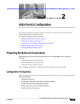
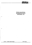
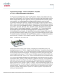
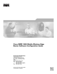
The MWR 1900 router is designed to be used at a cell site as part of an IP-RAN solution. Figure 1-1
shows the placement of and connections for the MWR 1900 router for this application.
Cisco MWR 1900 Mobile Wireless Edge Router Hardware Installation Guide
78-13982-02
1-1
Chapter 1
Overview of the Cisco MWR 1900 Router
Hardware Features
Figure 1-1
MWR 1900 in an IP-RAN Solution
Active
100BaseT
T1/E1 backhaul link to
IP RAN aggregation node
Standby
MWR 1900 IP BTS router pair
65827
pBTS
In the IP-RAN solution, the BTS site consists of a pair of MWR 1900 routers. The pair of MWR 1900
routers provides for an active and standby router for redundancy. A failure of the active MWR 1900
router causes the standby router to take over as the active router for the BTS site.
Each pair of MWR 1900 routers at the BTS site is identical in hardware configuration. They connect to
each other through the BTS via the Fast Ethernet interfaces. The individual backhaul links to an MWR
1900 router are cabled from a single T1/E1 termination block in the BTS, connecting to both the active
and standby routers utilizing a “Y” cable. The redundancy design to control the active/standby
transitions of the router pair leverages HSRP to control the relays on the VWIC-2MFT-T1-DIR (or
VWIC-2MFT-E1-DIR) in each router to ensure that the relays on the active router are closed and the
relays on the standby router are open to avoid double termination of the T1 (or E1).
Hardware Features
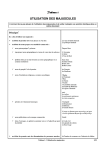
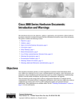
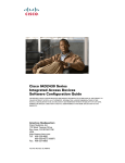
Figure 1-2 shows the front of the router. Figure 1-3 shows the back of the router.
Cisco MWR 1900 Mobile Wireless Edge Router Hardware Installation Guide
1-2
78-13982-02
Chapter 1
Overview of the Cisco MWR 1900 Router
Hardware Features
Figure 1-2
Front Panel of the Cisco MWR 1900 Router
VWIC LEDs:
Alarm (A)
Loopback (A)
Carrier detect (G)
Fast
ethernet
LEDs:
Activity (G)
Speed (G) VWIC
Link (G) position 2
SEE MAN
UAL BEFO
RE INST
ALLATION
VWIC LEDs:
Alarm (A)
Loopback (A)
Carrier detect (G)
VWIC
position 0
2 ports
DSU
56K
SEE MAN
UAL BEFO
RE INST
ALLATION
Figure 1-3
2 FE
ports
Compact
flash slot
E
AUXILIA
RY
Air vent (both sides)
Console
port
VWIC
position 1
2 ports
Auxiliary
port
Power (G)
Status (G)
Activity (G)
Chassis LEDs
65783
CONSOL
Network module
slot
Back Panel of the Cisco MWR 1900 Router
Rack mount bracket
(both sides)
Grounding
nut/screw
65784
Power
connector
Fan
The Cisco MWR 1900 router includes the following features:
•
Two DIMM-168 SDRAM (4 banks) sockets
•
SysAD bus speed and SDRAM local bus speed is 80Mhz
•
External Compact Flash (CF)
•
Two fixed LAN 10/100 Base-T Ethernet Ports
•
Three modular WIC/VIC expansion slots (1 for future use)
Cisco MWR 1900 Mobile Wireless Edge Router Hardware Installation Guide
78-13982-02
1-3
Chapter 1
Overview of the Cisco MWR 1900 Router
Fast Ethernet Interfaces
•
Redundancy support via a two T1/E1 WIC capable of port switching ON/OFF via relays
•
Console RS-232 port
•
Auxiliary Serial Port with hardware flow control
•
Extended operational temperature range from -10ºC to + 55ºC with over-temperature sensor
•
Front (connector side) to rear airflow using four 40mm, 10 CFM exhaust fans
•
Custom +27V DC input power
•
Three green chassis LEDs for Power (PS is operational), System Ready (software is up and running),
and Activity (interrupts/packet transfers running)
•
One Network Module slot (for future use)
Fast Ethernet Interfaces
The MWR 1900 router has two fixed LAN ports offering 10/100 Base-T Ethernet attachment. The ports
are fully compliant with the IEEE 802.3 and 802.3U standards and integrate the media access control
(MAC) functions and a dual-speed MII interface. Both ports can operate in half- or full-duplex mode and
can run independently of one another. For each FE interface, there are two green LEDs, one for Link
Integrity and one for Link Activity.
Voice/WAN Interface Cards
The Cisco VWIC-2MFT-T1-DIR and VWIC-2MFT-E1-DIR Voice/WAN Interface Cards support data
applications on the Cisco MWR 1900 Mobile Wireless Edge Router for T1/E1 networks. These cards are
dual-port, T1/Fractional T1 or E1/Fractional E1, Drop and Insert Multiplexers with integrated T1
CSU/DSUs or E1 DSUs. The T1 version supports framed and unframed traffic, and the E1 version
supports framed traffic and unframed traffic that conforms to the ITU-T G.703 standard for full 2.048
Mbps bandwidth.
The Drop and Insert multiplexer diverts (drops) streams of an aggregate Time Division Multiplexed
(TDM) traffic stream, and introduces (inserts) different streams for transmission in the time slots that
were previously occupied by the dropped streams. Each VWIC supports a limited channelized capability
where the T1 or E1 can be flexibly split into two fractional channel groups, one on each port or two on
one port. The switching operation can be maintained through router restarts and reloads of Cisco IOS
software.
Each card also features protection switch solid state relays on the line interfaces, which together with
redundancy logic and relay control added to the base Cisco IOS feature set on the MWR 1900, provides
T1/E1 Protection Switching between redundant routers.
The MWR 1900 router provides two WAN interface slots, which allows support for 4 T1/E1s. A third
WAN interface slot is reserved for future use.
Additional information is contained in separate publications that accompanied your router package.
•
For information on Voice/WAN interface cards (VWICs), see the publication VWIC-2MFT-T1DIR,
VWIC-2MFT-E1DIR Installation Instructions.
•
For software configuration information, see the publication Cisco MWR 1900 Software
Configuration Guide.
These manuals are on Cisco.com. See “Obtaining Documentation” for more information.
Cisco MWR 1900 Mobile Wireless Edge Router Hardware Installation Guide
1-4
78-13982-02
Chapter 1
Overview of the Cisco MWR 1900 Router
Compact Flash
Compact Flash
One external Compact Flash (CF) device is used on the MWR 1900 router. The CF memory size can vary
with a minimum size of 32Mbyte and a maximum size of 128Mbytes. This device is configured in
memory mapped mode (PCMCIA) to allow for hot insertion. This device is required for the MWR 1900
router to function because the IOS image and troubleshooting logs reside on this device. For information
about replacing or upgrading the CF, see the “Replacing or Upgrading the CF” section on page 3-10.
Overview of Cisco MWR 1900 Power Supplies
The MWR 1900 router is equipped with a +27 VDC power supply. The +27 VDC is typically used for
cell base stations.
Table 1-1 lists DC power supply specifications of the Cisco MWR 1900 router.
Table 1-1
Cisco MWR 1900 Power Supply Specifications
Specification
+27 VDC
Input voltage, DC power supply
Maximum input current
+ 20 to 32 VDC
2.2A
Wire gauge for DC-input power
connections2
18 AWG
Power Dissipation
44 W (typical)
Power Output
35 W (typical)
2
Only solid copper conductors shall be used for the DC input power connection.
The Cisco MWR 1900 router uses a small, three-wire connector for the power supply. The connector on
the Cisco MWR 1900 router is Phoenix Contact part number 1754452 and should mated with Phoenix
Contact part number 1754465, which is attached to the power cable.
Table 1-2 lists the pinout configuration for the connector for both power supplies.
Table 1-2
Power Supply Connectors Pinout
PIN
+27 VDC Power Supply
1
+ 27 VDC
2
Ground
3
RTN
Cisco MWR 1900 Mobile Wireless Edge Router Hardware Installation Guide
78-13982-02
1-5
Chapter 1
Overview of the Cisco MWR 1900 Router
Environmental Monitoring Temperature Sensor
Environmental Monitoring Temperature Sensor
The MWR 1900 router has a temperature sensor to detect over-temperature conditions inside the chassis.
The over-temperature detection trips at 75°C +/- 5%. This condition is reported to the processor as an
interrupt and software then takes action on this interrupt to generate the appropriate alarming. If the
router reaches a temperature of 90°C, the power supply will cycle to prevent the box from exceeding that
temperature in a powered up state.
System Specifications
Table 1-3 lists the Cisco MWR 1900 router system specifications.
Table 1-3
Cisco MWR 1900 Router System Specifications
Description
Specification
Dimensions (H x W x D)
1.72 x 17.5 x 12.5 in. (4.368 x 44.45 x 31.75 cm) 1RU/19.00 Rack
Mount
Weight
12 lb (5.443 kg)
Console and Auxiliary ports
RJ-45 connector
Operating Temperature
14 to 131°F (-10 to + 55°C)
Non-Operational Temperature
-40 to 158°F (-40 to 70°C)
Operating Humidity
5 to 90% RH (non-condensing
Operating Altitude
3000m @ 104°F (40°C)
Operating Vibration
0.41 Grms, 3 to 500 Hz/2 hours per axis
Non-Operational Vibration
1.12 Grms, 3 to 500 Hz/30 minutes per axis
Operating Acoustics
< 60 dBa
Regulatory Compliance
For regulatory compliance and safety information, see the Regulatory Compliance and Safety
Information for the Cisco MWR 1900 Mobile Wireless Edge Router document.
Cisco MWR 1900 Mobile Wireless Edge Router Hardware Installation Guide
1-6
78-13982-02
C H A P T E R
2
Preparing to Install the Router
This chapter describes site requirements and equipment needed to install your Cisco MWR 1900 router.
It includes the following sections:
•
Safety Recommendations, page 2-1
•
General Site Requirements, page 2-3
•
Installation Checklist, page 2-5
•
Console and Auxiliary Port Considerations, page 2-6
•
Inspecting the Router, page 2-4
•
Required Tools and Equipment for Installation and Maintenance, page 2-3
•
Console and Auxiliary Port Considerations, page 2-6
Safety Recommendations
Follow these guidelines to ensure general safety:
Warning
•
Keep the chassis area clear and dust-free during and after installation.
•
Keep tools away from walk areas where you or others could fall over them.
•
Do not wear loose clothing that may get caught in the chassis. Fasten your tie or scarf and roll up
your sleeves.
•
Wear safety glasses when working under conditions that may be hazardous to your eyes.
•
Do not perform any action that creates a potential hazard to people or makes the equipment unsafe.
Only trained and qualified personnel should be allowed to install or replace this
equipment.
Cisco MWR 1900 Mobile Wireless Edge Router Hardware Installation Guide
78-13982-02
2-1
Chapter 2
Preparing to Install the Router
Safety Recommendations
Safety with Electricity
Warning
Before performing any of the following procedures, ensure that power is removed from
the DC circuit. To ensure that all power is OFF, locate the circuit breaker on the panel
board that services the DC circuit, switch the circuit breaker to the OFF position, and
tape the switch handle of the circuit breaker in the OFF position.
Warning
This unit is intended for installation in restricted access areas. A restricted access area
is where access can only be gained by service personnel through the use of a special
tool, lock and key, or other means of security, and is controlled by the authority
responsible for the location.
Warning
The Ethernet 10/100BaseT, Token Ring, serial, console, and auxiliary ports contain safety
extra-low voltage (SELV) circuits. BRI circuits are treated like telephone-network
voltage (TNV) circuits. Avoid connecting SELV circuits to TNV circuits.
Warning
Before working on equipment that is connected to power lines, remove jewelry
(including rings, necklaces, and watches). Metal objects will heat up when connected
to power and ground and can cause serious burns or weld the metal object to the
terminals.
Warning
Before working on a chassis or working near power supplies, unplug the power cord on
AC units; disconnect the power at the circuit breaker on DC units.
Follow these guidelines when working on equipment powered by electricity:
•
Locate the room’s emergency power-OFF switch. Then, if an electrical accident occurs, you can
quickly shut the power OFF.
•
Before working on the system, turn the DC main circuit breaker off and disconnect the power
cord/terminal block cable.
•
Disconnect all power before doing the following:
– Working on or near power supplies
– Installing or removing a router chassis or network processor module
– Performing most hardware upgrades
•
Do not work alone if potentially hazardous conditions exist.
•
Look carefully for possible hazards in your work area, such as moist floors, ungrounded power
extension cables, and missing safety grounds.
•
Never assume that power is disconnected from a circuit. Always check.
•
If an electrical accident occurs, proceed as follows:
– Use caution, and do not become a victim yourself.
– Turn OFF power to the system.
Cisco MWR 1900 Mobile Wireless Edge Router Hardware Installation Guide
2-2
78-13982-02
Chapter 2
Preparing to Install the Router
General Site Requirements
– If possible, send another person to get medical aid. Otherwise, determine the condition of the
victim and then call for help.
– Determine if the person needs rescue breathing or external cardiac compressions; then take
appropriate action.
General Site Requirements
You can mount the Cisco MWR 1900 router in a 19-inch rack (with a 17.5- or 17.75-inch opening).
The following information will help you plan your equipment rack configuration:
•
Allow clearance around the rack for maintenance.
•
Enclosed racks must have adequate ventilation. Ensure that the rack is not congested, because each
router generates heat. An enclosed rack should have louvered sides and a fan to provide cooling air.
Heat generated by equipment near the bottom of the rack can be drawn upward into the intake ports
of the equipment above.
•
When mounting a chassis in an open rack, ensure that the rack frame does not block the intake or
exhaust ports. If the chassis is installed on slides, check the position of the chassis when it is seated
into the rack.
•
Baffles can help to isolate exhaust air from intake air, which also helps to draw cooling air through
the chassis. The best placement of the baffles depends on the airflow patterns in the rack, which can
be found by experimenting with different configurations.
•
When equipment installed in a rack (particularly in an enclosed rack) fails, try operating the
equipment by itself, if possible. Power OFF other equipment in the rack (and in adjacent racks) to
allow the router under test a maximum of cooling air and clean power.
Required Tools and Equipment for Installation and Maintenance
You need the following tools and equipment to install and upgrade the router and its components:
•
Number 2 Phillips screwdriver
•
Screws to fit your rack
•
Cables for connection to the WAN and LAN ports (dependent on configuration)
•
Ethernet hub or PC with a network interface card for connection to the Ethernet (LAN) port(s).
•
Console terminal (an ASCII terminal or a PC running terminal emulation software) configured for
9600 baud, 8 data bits, no parity, and 2 stop bits.
•
Modem for connection to the auxiliary port for remote administrative access (optional).
•
Console cable for connection to the console port. You can supply this cable yourself or order one
from Cisco (PN ACS-1900ASYN=).
•
Terminal block connector (Phoenix part number 1754465).
•
Ratcheting torque screwdriver with a Phillips head that exerts up to 15 pound-force inches (lbf-in)
of pressure.
•
Panduit crimping tool with optional controlled cycle mechanism, model CT-700, CT-720, CT-920,
CT-930, CT-920CH, or CT-940CH.
•
6-gauge copper ground wire (insulated or noninsulated).
Cisco MWR 1900 Mobile Wireless Edge Router Hardware Installation Guide
78-13982-02
2-3
Chapter 2
Preparing to Install the Router
Inspecting the Router
•
#6, ring-style ground lug.
•
18-AWG copper wire for the power cord.
•
Wire-stripping tool(s) for stripping both 6- and 18-gauge wires.
Inspecting the Router
Do not unpack the router until you are ready to install it. If the final installation site will not be ready
for some time, keep the chassis in its shipping container to prevent accidental damage. When you are
ready to install the router, proceed with unpacking it.
The router, cables, publications, and any optional equipment you ordered may be shipped in more than
one container. When you unpack the containers, check the packing list to ensure that you received all the
following items:
•
Router
•
Rack-mount brackets
•
This publication, the Regulatory Compliance and Safety Information document, optional companion
publications, or Documentation CD-ROM, as specified in your order
•
Cisco Information Packet publication
Inspect all items for shipping damage. If anything appears to be damaged, or if you encounter problems
installing or configuring your router, contact customer service. Warranty, service, and support
information is in the Cisco Information Packet that shipped with your router.
Creating a Site Log
The Site Log provides a record of all actions related to the router. Keep it in an accessible place near the
chassis where anyone who performs tasks has access to it. Use the Installation Checklist (a sample is
included in the following section) to verify steps in the installation and maintenance of the router. Site
Log entries might include the following:
•
Installation progress—Make a copy of the Installation Checklist and insert it into the Site Log. Make
entries as each procedure is completed.
•
Upgrade and maintenance procedures—Use the Site Log as a record of ongoing router maintenance
and expansion history. A Site Log might include the following events:
– Installation of network modules
– Removal or replacement of network modules and other upgrades
– Configuration changes
– Maintenance schedules and requirements
– Maintenance procedures performed
– Intermittent problems
– Comments and notes
Cisco MWR 1900 Mobile Wireless Edge Router Hardware Installation Guide
2-4
78-13982-02
Chapter 2
Preparing to Install the Router
Installation Checklist
Installation Checklist
The sample Installation Checklist lists items and procedures for installing a new router. Make a copy of
this checklist and mark the entries when completed. Include a copy of the checklist for each router in
your Site Log (described in the next section, “Console and Auxiliary Port Considerations”).
Installation Checklist for site
Router name
Task
Verified by
Date
Installation Checklist copied
Background information placed in Site Log
Site power voltages verified
Installation site power check completed
Required tools available
Additional equipment available
Router received
This publication and the Regulatory Compliance
and Safety Information document received
Optional printed documentation or CD-ROM
documentation received
Cisco Information Packet publication received
Chassis components verified
Initial electrical connections established
ASCII terminal (for local configuration) or
modem (for remote configuration)
Signal distance limits verified
Startup sequence steps completed
Initial operation verified
Software image verified
Cisco MWR 1900 Mobile Wireless Edge Router Hardware Installation Guide
78-13982-02
2-5
Chapter 2
Preparing to Install the Router
Console and Auxiliary Port Considerations
Console and Auxiliary Port Considerations
The router includes an asynchronous serial console port and an auxiliary port. The console and auxiliary
ports provide access to the router either locally using a console terminal, or remotely using a modem
connected to the auxiliary port. This section discusses important cabling information to consider before
connecting a console terminal, which can be either an ASCII terminal or a PC running terminal
emulation software, to the console port or modem to the auxiliary port.
The main difference between the console and auxiliary ports is that the auxiliary port supports hardware
flow control and the console port does not. Flow control paces the transmission of data between a
sending device and a receiving device. Flow control ensures that the receiving device can absorb the data
sent to it before the sending device sends more. When the buffers on the receiving device are full, a
message is sent to the sending device to suspend transmission until the data in the buffers has been
processed. Because the auxiliary port supports flow control, it is ideally suited for use with the
high-speed transmissions of a modem. Console terminals transmit at slower speeds than modems;
therefore, the console port is ideally suited for use with console terminals.
Note
Console and rollover cables are not included with the MWR 1900 router. You can order the
console cable from Cisco Systems (PN ACS-1900ASYN=). You must supply your own
rollover cable.
Console Port Connections
The router includes an EIA/TIA-232 asynchronous serial console port (RJ-45). Depending on the cable
and the adapter used, this port will appear as a data terminal equipment (DTE) or data communications
equipment (DCE) device at the end of the cable.
To connect an ASCII terminal to the console port, use the RJ-45 rollover cable with the female
RJ-45-to-DB-25 adapter (labeled TERMINAL). To connect a PC running terminal emulation software
to the console port, use the RJ-45 rollover cable with the female RJ-45-to-DB-9 adapter (labeled
TERMINAL). The default parameters for the console port are 9600 baud, 8 data bits, no parity, and 2
stop bits. The console port does not support hardware flow control. For detailed information about
installing a console terminal, see the “Connecting the Console Terminal and Modem” section on
page 3-2.
For cable and port pinouts, see the online document Cisco Modular Access Router Cable Specifications.
This document is located on the Documentation CD-ROM that accompanied your router, and on
Cisco.com.
Auxiliary Port Connections
The router includes an EIA/TIA-232 asynchronous serial auxiliary port (RJ-45) that supports flow
control. Depending on the cable and the adapter used, this port will appear as a DTE or DCE device at
the end of the cable.
To connect a modem to the auxiliary port, use the RJ-45 rollover cable with the male RJ-45-to-DB-25
adapter (labeled MODEM). For detailed information about connecting devices to the auxiliary port, see
the “Connecting the Console Terminal and Modem” section on page 3-2.
For cable and port pinouts, see the online document Cisco Modular Access Router Cable Specifications.
This document is located on the Documentation CD-ROM that accompanied your router, and Cisco.com.
Cisco MWR 1900 Mobile Wireless Edge Router Hardware Installation Guide
2-6
78-13982-02
C H A P T E R
3
Installing the Router
This chapter describes how to install your Cisco MWR 1900 router and connect it to networks and
external devices. It contains the following sections:
Warning
•
Rack Mounting the Chassis, page 3-1
•
Connecting the Console Terminal and Modem, page 3-2
•
Connecting the Network Cables, page 3-4
•
Connecting the MWR 1900 Router to a DC-Input Power Supply, page 3-7
•
Replacing or Upgrading the CF, page 3-10
•
What to Do After Installing the Hardware, page 3-16
Only trained and qualified personnel should be allowed to install or replace this
equipment.
Rack Mounting the Chassis
You can mount the Cisco MWR 1900 router in a 19-inch rack with the following rack openings and
chassis orientations:
Warning
•
17.5-inch opening, front panel forward
•
17.75-inch opening, front panel forward
To prevent bodily injury when mounting or servicing this unit in a rack, you must take
special precautions to ensure that the system remains stable. The following guidelines
are provided to ensure your safety:
This unit should be mounted at the bottom of the rack if it is the only unit in the rack.
When mounting this unit in a partially filled rack, load the rack from the bottom to the top
with the heaviest component at the bottom of the rack.
If the rack is provided with stabilizing devices, install the stabilizers before mounting or
servicing the unit in the rack.
Cisco MWR 1900 Mobile Wireless Edge Router Hardware Installation Guide
78-13982-02
3-1
Chapter 3
Installing the Router
Connecting the Console Terminal and Modem
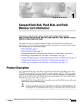
Attaching the Brackets
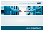
Attach the mounting brackets to the chassis as shown, using the screws provided in the bracket kit.
Attach the second bracket to the opposite side of the chassis. Use a number 2 Phillips screwdriver to
install the bracket screws.
Four screws are required on each side. Figure 3-1 shows how the bracket is attached.
Figure 3-1
BEFORE
INSTALLAT
ION
Attaching the Bracket
DSU
56K
SEE MA
NUAL BEF
ORE INS
TALLATION
CONSOL
AUXILIAR
Y
65785
E
Rack-mount bracket
Installing the Router in the Rack
Install the chassis in the rack. Rack-mounting screws are not provided with the router. Use two screws
for each side (supplied with the rack).
Installing a T1/E1 Multiflex VWIC
If your MWR 1900 router does not have a T1/E1 Multiflex VWIC installed of if you need to install an
additional T1/E1 Multiflex VWIC, see the VWIC-2MFT-T1-DIR, VWIC-2MFT-E1-DIR Installation
Instructions.
Caution
T1/E1 Multiflex VWICs do not support online insertion and removal (hot swapping). Before
inserting a card into the network module or router chassis, you must turn off electrical power and
disconnect network cables.
Connecting the Console Terminal and Modem
This section describes how to connect a console terminal and a modem to the router. You can connect
only a terminal to the console port. Use the auxiliary port with a terminal or a modem for remote access
to the router.
Cisco MWR 1900 Mobile Wireless Edge Router Hardware Installation Guide
3-2
78-13982-02
Chapter 3
Installing the Router
Connecting the Console Terminal and Modem
These ports provide administrative access to your router either locally (with a console terminal) or
remotely (with a modem).
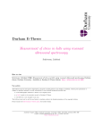
Identifying a Rollover Cable
Use a rollover cable to connect to the asynchronous serial console and auxiliary ports. You can identify
a rollover cable by comparing the two modular ends of the cable. Holding the cables side-by-side, with
the tab at the back, the wire connected to the pin on the outside of the left plug should be the same color
as the wire connected to the pin on the outside of the right plug. (See Figure 3-2.) If your cable came
from Cisco, pin 1 will be white on one connector, and pin 8 will be white on the other (a rollover cable
reverses pins 1 and 8, 2 and 7, 3 and 6, and 4 and 5).
Figure 3-2
Identifying a Rollover Cable
Pin 1 and pin 8
should be the
same color
Pin 8
H3824
Pin 1
Console Port
Take the following steps to connect a terminal or a PC running terminal emulation software to the
console port on the router:
Step 1
Connect the terminal using an RJ-45 rollover cable and an RJ-45-to-DB-25 or RJ-45-to-DB-9 adapter
(labeled TERMINAL).
Note
Step 2
The RJ-45-to-DB-25 adapter (Cisco part number 29-0810-01) can be purchased
from Cisco.
Configure your terminal or terminal emulation software for 9600 baud, 8 data bits, no parity, and 2 stop
bits.
Cisco MWR 1900 Mobile Wireless Edge Router Hardware Installation Guide
78-13982-02
3-3
Chapter 3
Installing the Router
Connecting the Network Cables
Note
Because hardware flow control is not possible on the console port, Cisco does not
recommend that modems be connected to the console port. Modems should always
be connected to the auxiliary port.
Auxiliary Port
Take the following steps to connect a modem to the auxiliary port on the router:
Step 1
Connect a modem to the auxiliary port using an RJ-45 rollover cable with an RJ-45-to-DB-25 adapter.
The provided adapter is labeled MODEM. For cable pinouts, see the online publication Cisco Modular
Access Router Cable Specifications available both on the Documentation CD-ROM and CCO.
Step 2
Make sure that your modem and the router auxiliary port are configured for the same transmission speed
(up to 115200 bps is supported) and hardware flow control with Data Carrier Detect (DCD) and Data
Terminal Ready (DTR) operations.
Connecting the Network Cables
The MWR 1900 router supports the following network connections:
•
Fast Ethernet
•
T1/E1 (through the VWIC)
Connecting the FE Interface Cables
The RJ-45 port supports standard straight-through and crossover Category 5 unshielded twisted-pair
(UTP) cables (refer to Figure 3-15). Cisco Systems does not supply Category 5 UTP cables; these cables
are available commercially.
Step 1
Confirm that the router is turned off.
Step 2
Connect one end of the cable to the FE port on the router.
Step 3
Connect the other end to the BTS patch or demarcation panel at your site.
Figure 3-3 shows the RJ-45 port and connector.
Cisco MWR 1900 Mobile Wireless Edge Router Hardware Installation Guide
3-4
78-13982-02
Chapter 3
Installing the Router
Connecting the Network Cables
RJ-45 Port and Plug
H2936
Figure 3-3
87654321
RJ-45 connector
Table 3-1 lists the pinouts and signals for the RJ-45 port.
Table 3-1
RJ-45 Pinout
Pin
Description
1
Receive Data + (RxD+)
2
RxD-
3
Transmit Data + (TxD+)
6
TxD-
Connecting the VWIC Interface Cables
How you connect the ports of the T1/E1 Multiflex VWIC depends on whether you are using the MWR
1900 router in a redundant or a non-redundant configuration.
For redundant configurations, use a Y-cable (as described in Y-Cable Specifications, page 3-6).
Note
HSRP and the Y-cable mode must be configured for redundancy to allow one router to become active
(CD LED on) and the other to become the standby (CD LED on, AL LED on due to no framing). For
more information, see the MWR 1900 Software Configuration Guide.
Step 1
Confirm that both routers are turned off.
Step 2
Connect the end of one of the Y-cable stubs to the T1 or E1 port on the card on the first router.
Step 3
Connect the end of the other Y-cable stub to the T1 or E1 port (using the same type of port as in Step 2)
on the card in the second router.
Step 4
Connect the other end of the Y-cable to the BTS patch or demarcation panel at your site.
Step 5
Turn on power to the routers.
Step 6
Check that the CD LEDs goes on, which means that the cards’ internal CSU/DSU is communicating
with the CSU/DSU at the T1 or E1 service provider central office.
For non-redundant configurations, use a straight-through, shielded RJ-48C-to-RJ-48C cable.
Cisco MWR 1900 Mobile Wireless Edge Router Hardware Installation Guide
78-13982-02
3-5
Chapter 3
Installing the Router
Connecting the Network Cables
Note
If you choose to use the T1/E1 Multiflex VWIC in a non-redundant configuration, you must close
the relays on the card using the standalone subcommand. For more information, see the “Cisco MWR
1900 Software Configuration Guide.”
Step 1
Confirm that the router is turned off.
Step 2
Connect one end of the cable to the T1 or E1 port on the card.
Step 3
Connect the other end to the BTS patch or demarcation panel at your site.
Step 4
Turn on power to the router.
Step 5
Check that the CD LED goes on, which means that the card’s internal CSU/DSU is communicating
with the CSU/DSU at the T1 or E1 service provider central office.
The T1/E1 Multiflex VWIC uses an RJ-48C connection, as shown in Figure 3-4.
RJ-48C Connection
87654321
RJ-48C connector
24939
Figure 3-4
Table 3-2 shows the pinout configuration of the RJ-48C connectors on the T1/E1 Multiflex VWIC.
Table 3-2
RJ-48C Pinout
Pin
Description
1
receive tip
2
receive ring
3
receive shield
4
transmit tip
5
transmit ring
6
transmit shield
7
not used
8
not used
Y-Cable Specifications
Although it can be used in a standalone MWR 1900 router, the T1/E1 Multiflex VWIC is designed to be
used in redundant configurations. Such configurations require a special Y-cable for connecting the active
and standby routers. The Y-cable provides a dual E1 or T1 PRI connection.
Cisco MWR 1900 Mobile Wireless Edge Router Hardware Installation Guide
3-6
78-13982-02
Chapter 3
Installing the Router
Connecting the MWR 1900 Router to a DC-Input Power Supply
This section describes the specifications of the Y-cable.
•
T1/E1 Multiflex VWIC Y-cables should be made with 4 twisted-pair, shielded, 28-gauge cables.
•
The cable length of each stub (from the RJ-48C connector to the junction point) should not exceed
3 inches (76 mm).
•
The cable length from junction point to the patch panel is determined by the customer.
MWR 1900
Stubs
E1/
T1
Junction point
Patch panel
MWR 1900
Y-Cable
65826
E1/
T1
•
All signals that propagate in the same direction must share the same twisted pair. For example, RX
TIP and RX RING must form a single twisted pair.
•
All unused twisted pairs should be cut flush on both ends of the cable. Any unused wire in a twisted
pair where one wire is in use should be cut flush at both ends.
Connecting the MWR 1900 Router to a DC-Input Power Supply
This section contains instructions for:
Warning
•
Required Tools and Equipment
•
Grounding the Router
•
Wiring the DC-Input Power Source
•
Powering On the Router
This unit is intended for installation in restricted access areas. A restricted access area
is where access can only be gained by service personnel through the use of a special
tool, lock and key, or other means of security, and is controlled by the authority
responsible for the location.
Required Tools and Equipment
You need the following tools and equipment:
•
Terminal block connector (Phoenix part number 1754465).
•
Ratcheting torque screwdriver with a Phillips head that exerts up to 15 pound-force inches (lbf-in)
of pressure.
•
Panduit crimping tool with optional controlled cycle mechanism, model CT-700, CT-720, CT-920,
CT-930, CT-920CH, or CT-940CH.
•
6-gauge copper ground wire (insulated or noninsulated).
Cisco MWR 1900 Mobile Wireless Edge Router Hardware Installation Guide
78-13982-02
3-7
Chapter 3
Installing the Router
Connecting the MWR 1900 Router to a DC-Input Power Supply
•
18-AWG copper wire for the power cord.
•
Wire-stripping tool(s) for stripping both 6- and 18-gauge wires.
Grounding the Router
Follow these steps to ground the router to earth ground. Make sure to follow any grounding requirements
at your site.
Warning
This equipment is intended to be grounded. Ensure that the host is connected to earth
ground during normal use.
Warning
When installing the unit, the ground connection must always be made first and
disconnected last.
Step 1
Remove the ground-lug screw from the rear panel of the router (shown in Figure 1-3). Use a standard
Phillips screwdriver or a ratcheting torque screwdriver with a Phillips head.
Step 2
Set the screw aside.
Step 3
If your ground wire is insulated, use a wire-stripping tool to strip the 6-gauge ground wire to 0.5 inch ±
0.02 inch (as shown below)
.
Insulation
Wire lead
10358
0.50" ± 0.02"
Slide the open end of your ground lug over the exposed area of the 6-gauge wire.
Step 5
Using a Panduit crimping tool, crimp the ground lug to the 6-gauge wire (as shown below).
10360
Step 4
Cisco MWR 1900 Mobile Wireless Edge Router Hardware Installation Guide
3-8
78-13982-02
Chapter 3
Installing the Router
Connecting the MWR 1900 Router to a DC-Input Power Supply
Step 6
Use the screw to attach the ground lug and wire assembly to the rear panel of the switch.
Step 7
Using a ratcheting torque screwdriver, torque the ground-lug screw to 15 1bf-in (or 240 ounce-force
inches [240 ozf-in]).
Wiring the DC-Input Power Source
Warning
Note
This product relies on the building’s installation or power supply for short circuit
(overcurrent) protection. Ensure that a listed and certified fuse or circuit breaker no
larger than 60 VDC, 15A U.S. is used on all current-carrying conductors.
The installation must comply with the 1996 National Electric Code (NEC) and other
applicable codes.
To connect the DC power supply to the Cisco MWR 1900 router, do the following:
Step 1
Turn OFF the DC power source at the circuit breaker and tape the circuit breaker in the OFF position.
Step 2
Connect one end of the customer-supplied power cord (18-AWG copper wire) to the DC power source.
Step 3
Attach the terminal block connector (Phoenix part number 1754465) to the other end of the power supply
cord. Ensure that the pinouts are configured properly. The pinouts are listed on the label beside the power
connector on the back of the MWR 1900 router.
Step 4
Plug the connector on the power supply cord into the MWR 1900 power supply connector, which is the
green connector on the right-hand side of the back of the MWR 1900 router.
Warning
An exposed wire lead from a DC-input power source can conduct harmful levels of
electricity. Be sure that no exposed portion of the DC-input power source wire extends
from the terminal block plug.
Warning
Secure all power cabling when installing this unit to avoid disturbing field-wiring
connections.
Powering On the Router
Warning
The plug-socket combination must be accessible at all times because it serves as the
main disconnecting device.
Cisco MWR 1900 Mobile Wireless Edge Router Hardware Installation Guide
78-13982-02
3-9
Chapter 3
Installing the Router
Replacing or Upgrading the CF
Warning
After wiring the DC power supply, remove the tape from the circuit breaker switch
handle and reinstate power by moving the handle of the circuit breaker to the ON
position.
Warning
Do not touch the power supply when the power cord is connected. For systems with a
power switch, line voltages are present within the power supply even when the power
switch is off and the power cord is connected. For systems without a power switch, line
voltages are present within the power supply when the power cord is connected.
Warning
This equipment is intended to be grounded. Ensure that the host is connected to earth
ground during normal use.
To power on the router, do the following:
Step 1
Turn on the power supply at the circuit breaker.
Step 2
The LED labeled PWR on the front panel should go on.
If you encounter problems when you power on the router, see Appendix A, “Troubleshooting.”.
Replacing or Upgrading the CF
This section describes how to remove, install, and format the external Compact Flash (CF).
The MWR 1900 router is shipped with a 32MB CF included. It contains the appropriate IOS software
image. However, you may need to replace or upgrade the CF at some point. If you do, follow the steps
outlined below. This procedure can also be used to make copies of the CF.
Step 1
Copy the desired IOS image to a remote TFTP server.
Step 2
Power up the MWR 1900 router to the ROMMON prompt.
Step 3
Boot the router with the existing IOS image.
Step 4
Remove the CF cover.
Step 5
Remove the current CF from the CF Slot. See Removing a CF Memory Card from an External Slot, page
3-11 for more information.
Step 6
Place a new CF into the CF Slot.
Step 7
Format the CF using the format slot0: command. See Formatting Procedures for CF Memory Cards,
page 3-12 for more information.
Step 8
Issue a copy tftp slot0: command to copy the customer-ordered IOS image from the remote TFTP server
back to the CF.
Cisco MWR 1900 Mobile Wireless Edge Router Hardware Installation Guide
3-10
78-13982-02
Chapter 3
Installing the Router
Replacing or Upgrading the CF
Note
Ensure that the IOS image is the first file on the CF. Otherwise, the router will not
boot. To avoid naming conflicts, we recommend that you copy the file as
mwr1900-i-mz.boot.
Step 9
Reboot the system to the ROMMON prompt.
Step 10
Boot the customer-ordered IOS image from the new CF.
Step 11
Upon successful booting of the image, replace the CF cover. If the boot process is unsuccessful, repeat
Step 6 through Step 10.
Removing a CF Memory Card from an External Slot
Complete the following steps to remove a CF memory card from an external slot:
Caution
Do not remove the CF memory card while it is performing a read or write operation,
because the router will shut down and the file system will be damaged.
Step 1
Locate the CF memory card in its slot in the front panel of the chassis. See Figure 1-2 on page 1-3.
Step 2
Move the release button, located next to the slot, to its fully extended position, and press the button to
unseat the card.
Step 3
Carefully pull the card out of the slot.
Step 4
Place the removed CF memory card on an antistatic surface or in a static shielding bag.
Installing a CF Memory Card in an External Slot
Complete the following steps to install a CF memory card:
Step 1
Locate the CF memory-card slot in the front panel of the chassis.See Figure 1-2 on page 1-3.
Step 2
With the label facing up, insert the connector end of the CF memory card into the slot until the card is
seated in the connector and the release button is pushed out. The card is keyed so that it cannot be
inserted wrong.
Step 3
Pull the release button out and move it to the left, to latch the card in the slot.
Step 4
Refer to the “Formatting Procedures for CF Memory Cards” section for instructions on formatting the
CF memory card.
Cisco MWR 1900 Mobile Wireless Edge Router Hardware Installation Guide
78-13982-02
3-11
Chapter 3
Installing the Router
Replacing or Upgrading the CF
Formatting Procedures for CF Memory Cards
For the Cisco MWR 1900 router, Cisco recommends that you format/erase new CF memory cards to
initialize them with a Class C Flash file system. This ensures proper formatting and enables the ROM
monitor to recognize and boot the Flash.
The Class C Flash file system is similar to the standard DOS file system; however, a CF memory card
formatted with the standard DOS file system does not support booting from the ROM monitor.
Formatting CF Memory as a DOS File System
To format a new external CF memory card, or to remove the files from a previously installed external CF
memory card, enter the format slot0: command.
The following example shows output for formatting a CF memory card formatted with a Class C Flash
file system:
Router# format slot0:
Format operation may take a while. Continue? [confirm]
Format operation will destroy all data in "slot0:". Continue? [confirm]
Enter volume ID (up to 64 chars)[default slot0]:
Current Low End File System flash card in flash will be formatted into DOS
File System flash card! Continue? [confirm]
Format:Drive communication & 1st Sector Write OK...
Writing Monlib sectors ...................................................................
Monlib write complete
..
Format:All system sectors written. OK...
Format:Total sectors in formatted partition:250592
Format:Total bytes in formatted partition:128303104
Format:Operation completed successfully.
Format of flash complete
File and Directory Procedures
The following sections describe file and directory procedures for external CF memory cards formatted
with a Class C Flash file system.
Copy Files
To copy the files to another location, use the copy slot0: source-filename { slot0: | tfp: | lex: | null: |
nvram: | pram: | rcp: | system: | tftp: | xmodem: | ymodem: | running-config | startup-config}
destination-filename command.
Cisco MWR 1900 Mobile Wireless Edge Router Hardware Installation Guide
3-12
78-13982-02
Chapter 3
Installing the Router
Replacing or Upgrading the CF
The following example shows output for copying a Cisco IOS file from an external CF memory card to
a TFTP server:
Router# copy slot0:mwr1900-i-mz.tmp tftp:
Destination filename [mwr1900-i-mz.tmp]?
CCCCCCCCCCCCCCCCCCCCCCCCCCCCCCCCCCCCCCCCCCCCCCCCCCCCCCCCCCCCCCCCCCCCCCCCCCCCCCCCCCCCCCCCCC
CCCCCCCCCCCCCCCCCCCCCCCCCCCCCCCCCCCCCCCCCCCCCCCCCCCCCCCCCCCCCCCCCCCCCCCCCCCCCCCCCCCCCCCCCC
CCCCCCCCCCCCCCCCCCCCCCCCCCCCCCCCCCCCCCCCCCCCCCCCCCCCCCCCCCCCCCCCCCCCCCCCCCCCCCCCCCCCCCCCCC
CCCCCCCCCCCCCCCCCCCCCCCCCCCCCCCCCCCCCCCCCCCCCCCCCCCCCCCCCCCCCCCCCCCCCCCCCCCCCCCCCCCCCCCCCC
CCCCCCCCCCCCCCCCCCCCCCCCCCCCCCCCCCCCCCCCCCCCCCCCCCCCCCCCCCCCCCCCCCCCCCCCCCCCCCCCCCCCCCCCCC
CCCCCCCCCCCCCCCCCCCCCCCCCCCCCCCCCCCCCCCCCCCCCCCCCCCCCCCCCCCCCCCCCCCCCCCCCCCCCCCCCCCCCCCCCC
CCCCCCCCCCCCCCCCCCCCCCCCCCCCCCCCCCCCCCCCCCCCCCCCCCCCCCCCCCCCCCCCCCCCCCCCCCCCCCCCCCCCCCCCCC
CCCCCCCCCCCCCCCCCCCCCCCCCCCCCCCCCCCCCCCCCCCCCCCCCCCCCCCCCCCCCCCCCCCCCCCCCCCCCCCCCCCCCCCCCC
CCCCCCCCCCCCCCCCCCCCCCCCCCCCCCCCCCCCCCCCCCCCCCCCCCCCCCCCCCCCCCCCCCCCCCCCCCCCCCCCCCCCCCCCCC
CCCCCCCCCCCCCCCCCCCCCCCCCCCCCCCCCCCCCCCCCCCCCCCCCCCCCCCCCCCCCCCCCCCCCCCCCCCCCCCCCCCCCCCCCC
CCCCCCCCCCCCCCCCCCCCCCCCCCCCCCCCCCCCCCCCCCCCCCCCCCCCCCCCCCCCCCCCCCCCCCCCCCCCCCCCCCCCCCCCCC
CCCCCCCCCCCCCCCCCCCCCCCCCCCCCCCCCCCCCCCCCCCCCCCCCCCCCCCCCCCCCCCCCCCCCCCCCCCCCCCCCCCCCCCCCC
CCCCCCCCCCCCCCCCCCCCCCCCCCCCCCCCCCCCCCCCCCCCCCCCCCCCCCCCCCCCCCCCCCCCCCCCCCCCCCCCCCCCCCCCCC
CCCCCCCCCCCCCCCCCCCCCCCCCCCCCCCCCCCCCCCCCCCCCCCCCCCCCCCCCCCCCCCCCCCCCCCCCCCCCCCCCCCCCCCCCC
CCCCCCCCCCCCCCCCCCCCCCCCCCCCCCCCCCCCCCCCCCCCCCCCCCCCCCCCCCCCCCCCCCCCCCCCCCCCCCCCCCCCCCCCCC
CCCCCCCCCCCCCCCCCCCCCCCCCCCCCCCCCCCCCCCCCCCCCCCCCCCCCCCCCCCCCCCCCCCCCCCCCCCCCCCCCCCCCCCCCC
CCCCCCCCCCCCCCCCCCCCCCCCCCCCCCCCCCCCCCCCCCCCCCCCCCCCCCCCCCCCCCCCCCCCCCCCCCCCCCCCCCCCCCCCCC
CCCCCCCCCCCCCCCCCCCCCCCCCCCCCCCCCCCCCCCCCCCCCCC
6458584 bytes copied in 202.940 secs (31973 bytes/sec)
Display the Contents of a CF Card
To display the contents (directories and files) of a CF memory card formatted with a Class C Flash file
system, use the dir slot0: command.
The following example shows output for displaying the contents of an external CF memory card with a
Class C Flash file system:
Router# dir slot0:
Directory of slot0:/
3
1579
-rw-rw-
6455048
6458584
Mar 01 2001 00:04:06
Mar 01 2001 00:24:38
mwr1900-i-mz
mwr1900-i-mz.new
15912960 bytes total (2998272 bytes free)
Display Geometry and Format Information
To display the geometry and format information of a CF memory card formatted with a Class C Flash
file system, use the show slot0: command.
Cisco MWR 1900 Mobile Wireless Edge Router Hardware Installation Guide
78-13982-02
3-13
Chapter 3
Installing the Router
Replacing or Upgrading the CF
The following example shows output for displaying the geometry and format information of an external
CF memory card formatted with a Class C Flash file system:
Router# show slot0:
******** ATA Flash Card Geometry/Format Info ********
ATA CARD GEOMETRY
Number of Heads:
2
Number of Cylinders
490
Sectors per Cylinder
32
Sector Size
512
Total Sectors
31360
ATA CARD FORMAT
Number of FAT Sectors
Sectors Per Cluster
Number of Clusters
Number of Data Sectors
Base Root Sector
Base FAT Sector
Base Data Sector
12
8
3885
31264
152
128
184
Please use "dir" command to display the contents of the card.
Delete Files from Flash
To delete a file from a CF memory card, use the delete slot0: filename command.
The following example shows output for deleting a Cisco IOS file from an external CF card:
Router# delete slot0:mwr1900-i-mz.tmp
Delete filename [mwr1900-i-mz.tmp]?
Delete slot0:mwr1900-i-mz.tmp? [confirm]
Router# dir slot0:
Directory of slot0:/
No files in directory
128094208 bytes total (128094208 bytes free)
Rename a File in Flash
To rename a file in a CF memory card, use the rename slot0: original-filename slot0: new-filename
command.
The following example shows output for renaming a Cisco IOS file in an external CF card:
Router# rename slot0:mwr1900-i-mz.tmp slot0:mwr1900-i-mz
Destination filename [mwr1900-i-mz]?
Router# dir slot0:
Directory of slot0:/
1580
3
-rw-rw-
6462268
6458388
Mar 06 1993 06:14:02
Mar 01 1993 00:01:24
mwr1900-i-mz.1900ata
mwr1900-i-mz
63930368 bytes total (51007488 bytes free)
Cisco MWR 1900 Mobile Wireless Edge Router Hardware Installation Guide
3-14
78-13982-02
Chapter 3
Installing the Router
Replacing or Upgrading the CF
Display File Content
To display the content of a file in a CF memory card, use the more slot0: filename command.
The following example shows output from the more command on an external CF card:
Router# more slot0:mwr1900-i-mz.tmp
00000000: 7F454C46
00000010: 00020061
00000020: 00000054
00000030: 00050008
00000040: 80008000
00000050: 0000011C
00000060: 80008000
00000070: 00000000
00000080: 00000001
00000090: 00000700
000000A0: 00000000
000000B0: 8000C700
000000C0: 00000000
000000D0: 00000001
000000E0: 00000020
000000F0: 00000000
00000100: 8000CAA0
00000110: 00000000
00000120: 679C4A80
00000130: AC3FC710
00000140: AC25C718
00000150: AC27C720
00000160: AC31C728
--More-- q
01020100
00000001
20000001
00000001
00628A44
0000001B
0000011C
00000008
00000002
00000000
00000029
0000481C
00000004
10000003
00000000
0000002F
00004BBC
00000008
3C018001
3C018001
3C018001
3C018001
3C018001
00000000
80008000
00340020
0000011C
00650EEC
00000001
00004000
00000000
8000C000
00000000
00000001
00000380
00000000
8000CA80
00000000
00000001
00623FA4
00000000
AC3DC70C
AC24C714
AC26C71C
AC30C724
AC32C72C
00000000
00000034
00010028
80008000
00000007
00000006
00000000
00000021
0000411C
00000004
00000003
00000000
0000002F
00004B9C
00000008
10000003
00000000
3C1C8001
3C018001
3C018001
3C018001
3C018001
3C018001
.ELF
...a
...T
....
....
....
....
....
....
....
....
..G.
....
....
...
....
..J
....
g.J.
,?G.
,%G.
,'G
,1G(
....
....
...
....
.b.D
....
....
....
....
....
...)
..H.
....
....
....
.../
..K<
....
<...
<...
<...
<...
<...
....
....
.4.
....
.e.l
....
..@.
....
..@.
....
....
....
....
..J.
....
....
.b?$
....
,=G.
,$G.
,&G.
,0G$
,2G,
....
...4
...(
....
....
....
....
...!
..A.
....
....
....
.../
..K.
....
....
....
<...
<...
<...
<...
<...
<...
Create a New Directory
To create a directory in CF memory, use the mkdir slot0: directory-name command.
The following example shows output for first displaying the contents of an external CF card, and then
creating a directory named config and a subdirectory named test-config:
Router# dir slot0:
Directory of slot0:/
3
-rw-
6458208
Mar 01 1993 00:04:08
mwr1900-i-mz.tmp
128094208 bytes total (121634816 bytes free)
Router# mkdir slot0:/config
Create directory filename [config]?
Created dir slot0:/config
Router# mkdir slot0:/config/test-config
Create directory filename [/config/test-config]?
Created dir slot0:/config/test-config
Router# dir slot0:
Directory of slot0:/
3 -rw1580 drw-
6458208
0
Mar 01 1993 00:04:08 mwr1900-i-mz.tmp
Mar 01 1993 23:48:36 config
128094208 bytes total (121626624 bytes free)
Cisco MWR 1900 Mobile Wireless Edge Router Hardware Installation Guide
78-13982-02
3-15
Chapter 3
Installing the Router
What to Do After Installing the Hardware
Router# cd slot0:/config
Router# dir slot0:
Directory of slot0:/config/
1581
drw-
0
Mar 01 1993 23:50:08
test-config
128094208 bytes total (121626624 bytes free)
Remove a Directory
To remove a directory from CF memory, use the rmdir slot0:/directory-name command.
Before you can remove a directory, all files and subdirectories must be removed from the directory.
The following example shows output for displaying the contents of an external CF card, then removing
the subdirectory named test-config:
Router# dir slot0:
Directory of slot0:/config/
1581
drw-
0
Mar 01 1993 23:50:08
test-config
128094208 bytes total (121626624 bytes free)
Router# rmdir slot0:/config/test-config
Remove directory filename [/config/test-config]?
Delete slot0:/config/test-config? [confirm]
Removed dir slot0:/config/test-config
Router# dir slot0:
Directory of slot0:/config/
No files in directory
128094208 bytes total (121630720 bytes free)
Enter a Directory and Determine the Current Directory
To enter a directory in CF memory, use the cd slot0:/directory-name command. To determine which
directory you are in, use the pwd command.
The following example shows output for the following actions:
•
Entering the home directory of a CF memory card in an external slot (slot0:/)
•
Verifying that you are in the slot0:/ directory
Router# cd slot0:
Router# pwd
slot0:/
What to Do After Installing the Hardware
When you have installed the router hardware, see the Cisco MWR 1900 Software Configuration Guide
included in your router package for initial software configuration information.
Cisco MWR 1900 Mobile Wireless Edge Router Hardware Installation Guide
3-16
78-13982-02
A P P E N D I X
A
Troubleshooting
Your Cisco MWR 1900 router goes through extensive testing before leaving the factory. If you encounter
problems, use the information in this appendix to help isolate problems or to eliminate the router as the
source of the problem.
This appendix contains the following sections:
•
Problem Solving, page A-1
•
Reading the LEDs, page A-3
If you cannot locate the source of the problem, contact a customer service representative for information
on how to proceed. For technical support information, see the Cisco Information Packet publication that
shipped with your router. Before you call, have the following information ready:
•
Chassis type and serial number
•
Maintenance agreement or warranty information
•
Type of software and version number
•
Date you received the new chassis
•
Brief description of the problem
•
Brief explanation of the steps you have taken to isolate the problem
Problem Solving
The key to problem solving is to isolate the problem to a specific subsystem by comparing what the
router is doing to what it should be doing.
The LEDs on the front panel of the router enable you to determine router performance and operation.
For a description of these LEDs, see Reading the LEDs, page A-3.
When problem solving, consider the following router subsystems:
•
Power and cooling systems—External power source, power cable, router power supply and circuit
breaker, and router blower and fan. Also consider inadequate ventilation or air circulation.
•
Modules—LEDs on the modules help identify a failure.
•
Cables—External cables that connect the router to the network.
Cisco MWR 1900 Mobile Wireless Edge Router Hardware Installation Guide
78-13982-02
A-1
Appendix A
Troubleshooting
Problem Solving
Troubleshooting the Power and Cooling Systems
Both the power LED and the fans can help you troubleshoot a power problem. Check the following items
to help isolate the problem:
Check the following items to help isolate problems with the power supply installation:
•
With the MWR 1900 router connected to the power source, is the power LED on the front panel on?
– If not, check the DC input, DC source, and the power supply wiring.
– Check the power supply connection to the motherboard.
– If the power LED is still off, the problem might be a power supply failure.
•
Does the router shut down after being on a short time?
– Check the fans. If the fans are not working, the router will overheat and shut itself down.
– If the fans are not working, check the power supply connections to the fans.
– Ensure that the chassis intake and exhaust vents are clear.
Check the environmental site requirements in the “System Specifications” section on page 1-6.
•
Does the router partially boot, but the LEDs do not go on?
– Check for a power supply failure by inspecting the power LED on the front panel of the router.
If the power LED is on, the power supply is functional.
– If the power LED is not on, refer to the Cisco Information Packet for warranty information or
contact customer service.
Environmental Reporting Features
The MWR 1900 router has a temperature sensor to detect over-temperature conditions inside the chassis.
The over-temperature detection trips at 75°C +/- 5%. This condition is reported to the processor as an
interrupt and software then takes action on this interrupt to generate the appropriate alarming. If the
router reaches a temperature of 90°C, the power supply will cycle to prevent the box from exceeding that
temperature in a powered up state.
If the router is operating at an abnormally high temperature, you see the following message on the
console screen:
%SYS-1-OVERTEMP: System detected OVERTEMPERATURE condition. Please resolve cooling problem
immediately!
Some causes of abnormally high router temperature are:
•
Fan failure
•
Air conditioner failure in the room
•
Air blockage to cooling vents
Take steps to correct the problem. For information about environmental operating conditions, see
“System Specifications” section on page 1-6.
Cisco MWR 1900 Mobile Wireless Edge Router Hardware Installation Guide
A-2
78-13982-02
Appendix A
Troubleshooting
Reading the LEDs
Troubleshooting Modules, Cables, and Connections
Network problems can be caused by a module, cables or cable connections, or external devices such as
a modem, transceiver, hub, wall jack, WAN interface, or terminal. Check for the following symptoms to
help isolate the problem:
•
Module is not recognized by the router.
– Make sure the module is firmly seated in its slot.
– Check the LEDs on the module. Each module has its own set of LEDs. For information on these
LEDs, see Reading the LEDs, page A-3.
– Make sure you have a version of Cisco IOS software that supports the module.
•
Module is recognized, but interface ports do not initialize.
– Make sure the module is firmly seated in its slot.
– Check external cable connections.
– Make sure you have a version of Cisco IOS software that supports the module.
•
Router does not boot properly, or constantly or intermittently reboots.
– Make sure the module is firmly seated in its slot.
– Check the router chassis or software. Refer to the Cisco Information Packet publication that
shipped with your router for warranty information, or contact customer service.
•
Router boots, but the console screen is frozen.
– Check the external console connection.
– Verify that the parameters for your terminal are set as follows:
(a) The same data rate as configured for the router (9600 bps is the default)
(b) 8 data bits
(c) No parity generated or checked
(d) 2 stop bits
•
Router powers on and boots only when a particular module is removed.
– Check the module. Refer to the Cisco Information Packet publication that accompanied your
order for warranty information, or contact customer service.
•
Router powers on and boots only when a particular cable is disconnected.
– There may be a problem with the module or cable. Refer to the Cisco Information Packet
publication for warranty information, or contact customer service.
Reading the LEDs
The LEDs on the front panel of the router enable you to determine router performance and operation.
Figure A-1 shows the locations of the LEDs.
Cisco MWR 1900 Mobile Wireless Edge Router Hardware Installation Guide
78-13982-02
A-3
Appendix A
Troubleshooting
Reading the LEDs
Figure A-1
Front Panel of the MWR 1900
VWIC LEDs:
Alarm (A)
Loopback (A)
Carrier detect (G)
Fast
ethernet
LEDs:
Activity (G)
Speed (G) VWIC
Link (G) position 2
SEE MAN
UAL BEFO
RE INST
ALLATION
VWIC LEDs:
Alarm (A)
Loopback (A)
Carrier detect (G)
VWIC
position 0
2 ports
DSU
56K
SEE MAN
UAL BEFO
RE INST
ALLATION
Table A-1
2 FE
ports
Compact
flash slot
E
AUXILIA
RY
Air vent (both sides)
Console
port
VWIC
position 1
2 ports
Auxiliary
port
Power (G)
Status (G)
Activity (G)
Chassis LEDs
Chassis LEDs
LED
Color
Status
Power
Green
Operating voltages on the mainboard are within acceptable ranges.
Off
The router is not connected to a power supply or an error condition has
been detected in the operating voltages.
Green
The router’s software has booted up and the system is operational.
Off
The router has not yet booted or an error condition has been detected in
the boot process.
Green
Packets or interrupts are being sent or received by the router.
Off
No activity.
Status
Activity
Table A-2
Fast Ethernet Connector LEDs
LED
Color
Status
Activity
Green
Data is being transmitted on the link.
Off
No data is being transmitted.
Green
100 Mbps communication speed attained.
Off
10 Mbps communication speed attained, or no link established.
Green
Ethernet link is established.
Off
No established link.
Speed
Link
65783
CONSOL
Network module
slot
Cisco MWR 1900 Mobile Wireless Edge Router Hardware Installation Guide
A-4
78-13982-02
Appendix A
Troubleshooting
Reading the LEDs
Table A-3
VWIC LEDs
LED
Color
Description
Loopback
Amber
A loopback or line state is detected or is manually set by the user.
Off
Normal operation.
Amber
A local or remote alarm state.
Off
Normal operation.
Alarm
Carrier Detect Green
Off
Note
A carrier has been detected and the internal DSU/CSU in the WAN
interface card is communicating with another DSU/CSU. This LED is on
during normal operation.
No carrier has been detected.
In a redundant configuration, when the relays of the VWIC open, the Carrier Detect LED
on the T1 ports will remain lit and the Alarm LED will also come on. Therefore, the
inactive router will show both the Carrier Detect light and the Alarm light, while the active
router will show only the Carrier Detect light.
Cisco MWR 1900 Mobile Wireless Edge Router Hardware Installation Guide
78-13982-02
A-5
Appendix A
Troubleshooting
Reading the LEDs
Cisco MWR 1900 Mobile Wireless Edge Router Hardware Installation Guide
A-6
78-13982-02
I N D E X
network cables
Numerics
power supply
2-port T1/E1 VWIC
connecting
3-5
description
1-4
3-4
3-7
VWIC interface cables
3-5
console port
connections
pinout specifications
3-6
2-6, 3-2, 3-3
considerations
2-6
conventions, documentation
vi
A
audience
D
v
auxiliary port
connecting
dimensions, chassis
3-4
connections
documentation
2-6, 3-4
considerations
1-6
conventions
2-6
obtaining
vi
viii
organization
v
B
back panel
E
1-3
equipment
for installation
C
racks
chassis, dimensions
checklist, installation
2-3
2-3
1-6
2-5
Cisco Information Packet publication
compact flash
2-4
F
fast ethernet
description
1-5
connecting interface cables
formatting
3-12
interfaces, description
replacing or upgrading
3-10
pinout specifications
connecting
formatting compact flash
auxiliary port
console port
3-4
1-4
3-5
3-12
1-3
3-2
fast ethernet interface cables
modem
front panel
3-4
3-4
3-2
Cisco MWR 1900 Mobile Wireless Edge Router Hardware Installation Guide
78-13982-02
IN-1
Index
G
P
general site requirements
packing list
2-3
2-4
pinout specifications
fast ethernet
H
VWIC
3-6
powering on
hardware
features
3-9
power supply
1-2
installing
3-5
3-1
troubleshooting procedures
A-1
connecting
3-7
description
1-5
warnings
3-9
problem solving
I
See troubleshooting
installation
checklist
2-5
compact flash
hardware
R
3-11
rack-mounting
3-1
rack-mounting
tools required
brackets
3-1
equipment
2-3
fast ethernet, description
VWIC, description
regulatory compliance
1-4
1-1
1-6
3-11
replacing compact flash
3-10
RJ-48C
3-5
3-6
rollover cable, identifying
A-3
router features
2-4
M
S
modules
safety
information
1-4
overview
warnings
3-4
3-3
1-2
1-6
vii
recommendations
N
network cables, connecting
2-6
removing compact flash
RJ-45
L
LEDs, front panel
3-1
record keeping, site log
1-4
IP-RAN, using the MWR 1900
VWIC
2-3
instructions
interfaces
log, site
3-2
2-1
3-9
site log, record keeping
specifications, system
2-6
1-6
Cisco MWR 1900 Mobile Wireless Edge Router Hardware Installation Guide
IN-2
78-13982-02
Index
system installation procedures
system specifications
3-4
1-6
T
tools required for installation
2-3
troubleshooting
cables
A-3
connections
A-3
cooling system
A-2
front panel LEDs
modules
A-3
A-3
power system
A-2
U
upgrading compact flash
3-10
V
ventilation
2-3
VWIC
See 2-port T1/E1 VWIC
W
warning
access to plug-socket
3-9
DC power connection
3-10
exposed wires
grounding
3-9
3-10
power supply
3-10
restricted access
3-7
restricted area
3-7
secure cabling
3-9
short circuit
3-9
warnings
safety overview
vii
Cisco MWR 1900 Mobile Wireless Edge Router Hardware Installation Guide
78-13982-02
IN-3
Index
Cisco MWR 1900 Mobile Wireless Edge Router Hardware Installation Guide
IN-4
78-13982-02