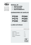
1
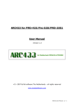
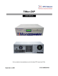
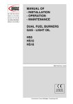
B U R N E R S
BRULEURS
B R E N N E R
QUEMADORES
B R U C I AT O R I
MANUAL FOR
- INSTALLATION
- OPERATION
- MAINTENANCE
LIGHT OIL BURNERS
G18 G-.SP
PG25 G-.SP
PG30 G-.TN
M03978CA Rev. 00 10/99
PARTE I:
FOREWORD
Page 2
INSTALLATION
Page 4
PARTE II: OPERATION
Page 11
PARTE III: MAINTENANCE
Page 12
APPENDIX
Page 18
Complying with
EMC 89/336/CEE
LV 73/23/CEE
Technical Documentation CIB Unigas S.p.a. - Campodarsego (PD)
PREFACE
THIS MANUAL IS SUPPLIED AS AN INTEGRAL AND ESSENTIAL PART OF THE PRODUCT AND MUST BE DELIVERED
TO THE USER.
INFORMATION INCLUDED IN THIS SECTION ARE DEDICATED BOTH TO THE USER AND TO PERSONNEL FOLLOWING
PRODUCT INSTALLATION AND MAINTENANCE.
THE USER WILL FIND FURTHER INFORMATIONS ABOUT OPERATING AND USE RESTRICTIONS, IN THE SECOND
SECTION OF THIS MANUAL. WE HIGHLY COMMEND TO READ IT.
CAREFULLY KEEP THIS MANUAL FOR FUTURE REFERENCE.
1) GENERAL INTRODUCTION
2) SPECIAL INSTRUCTIONS FOR BURNERS
The equipment must be installed in compliance with the
regulations in force, following the manufacturer’s instructions,
by qualified personnel.
Qualified personnel means those having technical knowledge
in the field of components for civil or industrial heating
systems, sanitary hot water generation and particularly
service centres authorised by the manufacturer.
Improper installation may cause injury to people and animals,
or damage to property, for which the manufacturer cannot be
held liable.
* Remove all packaging material and inspect the equipment
for integrity.
In case of any doubt, do not use the unit - contact the supplier.
The packaging materials (wooden crate, nails, fastening
devices, plastic bags, foamed polystyrene, etc), should not be
left within the reach of children, as they may prove harmful.
* Before any cleaning or servicing operation, disconnect the
unit from the mains by turning the master switch OFF, and/or
through the cut-out devices that are provided.
* Make sure that inlet or exhaust grilles are unobstructed.
* In case of breakdown and/or defective unit operation,
disconnect the unit. Make no attempt to repair the unit or take
any direct action.
Contact qualified personnel only.
Units shall be repaired exclusively by a servicing centre, duly
authorised by the manufacturer, with original spare parts.
Failure to comply with the above instructions is likely to impair
the unit’s safety.
To ensure equipment efficiency and proper operation, it is
essential that maintenance operations are performed by
qualified personnel at regular intervals, following the
manufacturer’s instructions.
* When a decision is made to discontinue the use of the
equipment, those parts likely to constitute sources of danger
shall be made harmless.
* In case the equipment is to be sold or transferred to another
user, or in case the original user should move and leave the
unit behind, make sure that these instructions accompany the
equipment at all times so that they can be consulted by the
new owner and/or the installer.
* For all the units that have been modified or have options
fitted then original accessory equipment only shall be used.
* This unit shall be employed exclusively for the use for which
it is meant. Any other use shall be considered as improper
and, therefore, dangerous.
The manufacturer shall not be held liable, by agreement or
otherwise, for damages resulting from improper installation,
use and failure to comply with the instructions supplied by the
manufacturer.
*The burner should be installed in a suitable room, with
ventilation openings complying with the requirements of the
regulations in force, and sufficient for good combustion.
* Only burners designed according to the regulations in force
should be used.
* This burner should be employed exclusively for the use for
which it was designed.
* Before connecting the burner, make sure that the unit rating
is the same as delivery mains (electricity, gas oil, or other fuel).
*Observe caution with hot burner components. These are,
usually, near to the flame and the fuel pre-heating system,
they become hot during the unit operation and will remain hot
for some time after the burner has stopped.
* When the decision is made to discontinue the use of the
burner, the user shall have qualified personnel carry out the
following operations:
a) Remove the power supply by disconnecting the power cord
from the mains.
b) Disconnect the fuel supply by means of the hand-operated
shut-off valve and remove the control handwheels from their
spindles.
Special warnings
2
* Make sure that the burner has, on installation, been firmly
secured to the appliance, so that the flame is generated inside
the appliance firebox.
* Before the burner is started and, thereafter, at least once a
year, have qualified personnel perform the following
operations:
a) set the burner fuel flow rate depending on the heat input of
the appliance;
b) set the flow rate of the combustion-supporting air to obtain a
combustion efficiency level at least equal to the lower level
required by the regulations in force;
c) check the unit operation for proper combustion, to avoid any
harmful or polluting unburnt gases in excess of the limits
permitted by the regulations in force;
d) make sure that control and safety devices are operating
properly;
e) make sure that exhaust ducts intended to discharge the
products of combustion are operating properly;
f) on completion of setting and adjustment operations, make
sure that all mechanical locking devices of controls have been
duly tightened;
g) make sure that a copy of the burner use and maintenance
instructions is available in the boiler room.
* In case of repeated burner shut-downs, do not continue resetting the unit manually. Contact qualified personnel to take
care of such defects.
* The unit shall be operated and serviced by qualified
personnel only, in compliance with the regulations in force.
FOREWORD
3) GENERAL INSTRUCTIONS DEPENDING ON FUEL USED
3B) FIRING WITH GAS, GASOIL OR OTHER FUELS
3A) ELECTRICAL CONNECTION
GENERAL
* For safety reasons the unit must be efficiently earthed and
installed as required by current safety regulations.
* It is vital that all saftey requirements are met. In case of any
doubt, ask for an accurate inspection of electrics by qualified
personnel, since the manufacturer cannot be held liable for
damages that may be caused by failure to correctly earth the
equipment.
* Qualified personnel must inspect the system to make sure
that it is adequate to take the maximum power used by the
equipment shown on the equipment rating plate. In particular,
make sure that the system cable cross section is adequate for
the power absorbed by the unit.
* No adaptors, multiple outlet sockets and/or extension cables
are permitted to connect the unit to the electric mains.
An omnipolar switch shall be provided for connection to mains,
as required by the current safety regulations.
The use of any power-operated component implies
observance of a few basic rules, for example:
- do not touch the unit with wet or damp parts of the body and/
or with bare feet;
- do not pull electric cables;
- do not leave the equipment exposed to weather (rain, sun,
etc.) unless expressly required to do so;
- do not allow children or inexperienced persons to use
equipment;
* The unit input cable shall not be replaced by the user.
In case of damage to the cable, switch off the unit and contact
qualified personnel to replace.
* When the unit is out of use for some time the electric switch
supplying all the power-driven components in the system (i.e.
pumps, burner, etc.) should be switched off.
* The burner shall be installed by qualified personnel and in
compliance with regulations and provisions in force; wrong
installation can cause injuries to people and animals, or
damage to property, for which the manufacturer cannot be
held liable.
* Before installation, it is recommended that all the fuel supply
system pipes be carefully cleaned inside, to remove foreign
matter that might impair the burner operation.
* Before the burner is commissioned, qualified personnel
should inspect the following:
a) the fuel supply system, for proper sealing;
b) the fuel flow rate, to make sure that it has been set based on
the firing rate required of the burner;
c) the burner firing system, to make sure that it is supplied for
the designed fuel type;
d) the fuel supply pressure, to make sure that it is included in
the range shown on the rating plate;
e) the fuel supply system, to make sure that the system
dimensions are adequate to the burner firing rate, and that the
system is equipped with all the safety and control devices
required by the regulations in force.
* When the burner is to remain idle for some time, the fuel
supply tap or taps should be closed.
SPECIAL INSTRUCTIONS FOR USING GAS
* Have qualified personnel inspect the installation to ensure
that:
a) the gas delivery line and train are in compliance with the
regulations and provisions in force;
b) all gas connections are tight;
c) the boiler room ventilation openings are such that they
ensure the air supply flow required by the current regulations,
and in any case are sufficient for proper combustion.
* Do not use gas pipes to earth electrical equipment.
* Never leave the burner connected when not in use. Always
shut the gas valve off.
* In case of prolonged absence of the user, the main gas
delivery valve to the burner should be shut off.
Precautions if you can smell gas
a) do not operate electric switches, the telephone, or any other
item likely to generate sparks;
b) immediately open doors and windows to create an air flow
to purge the room;
c) close the gas valves;
d) contact qualified personnel.
* Do not obstruct the ventilation openings of the room where
gas appliances are installed, to avoid dangerous conditions
such as the development of toxic or explosive mixtures.
FOREWORD
3
PART I: INSTALLATION MANUAL
TECHNICAL DATA
BURNER TYPE
Input
min kcal/h
max kcal/h
min kW
max kW
kg/h min.
kg/h max.
Oil firing rate
Fuel
Electrical supply
Frequency
Motor 2800 g/1'
A absorbed
Total power absorption
kW
A
kW
Operation
G18 SP
PG25 SP
PG30 TN
90.300
180.000
105
209
9
18
light oil
230V
50 Hz
0.25
1.5
0.55
140.200
250.200
163
291
14
25
light oil
230V
50 Hz
0.37
2.2
0.87
Soft start
Soft start
140.200
300.000
163
349
14
30
light oil
230V
50 Hz
0.37
2.2
0.87
Single
stage
BURNER MODEL IDENTIFICATION
Burners are identified by burner type and model. Burner type identification is described as follow:
Type: G18
(1)
Model:
G-.
(2)
SP.
(3)
S.
(4)
*.
(5)
A.
(6)
(1) BURNER TYPE
G18 SP - PG25 SP - PG30 TN
(2) FUEL
G = Light oil (Viscosity at 20°C 5 cSt)
(3) ADJUSTMENT
SP = Soft Start
TN = Single Stage
(4) BLAST TUBE LENGHT (See overall dimensions)
S = Standard
L = Long
(5) DESTINATION COUNTRY
* see data plate
(6) SPECIAL VERSIONS
A = Standard
OVERALL DIMENSIONS
G18SP
A
275
B
90
BL
200
C
365
CL
475
D
340
E
255
G
115
Fig. 1
4
INSTALLATION
K
230
H
P
125 121÷134
M
M8
OVERALL DIMENSIONS
PG25SP
PG30SP
A
B
BL
C
CL
D
E
F
G
K
H
P
M
515
155
345
660
850
267
260
520
133
290
125
155
M10
Fig. 1a
Back pressure in
combustion chamber mbar
PERFORMANCE CURVES
1.8
1.6
1.4
1.2
1
0.8
0.6
0.4
0.2
0
Fig. 2
6
8
10
12
14
16
18
20
Back pressure in
combustion chamber mbar
Oil rate Kg/h
4
3
2
Fig. 3
1
0
-1
10
12
14
16
18
20
22
24
26
28
30
Back pressure in
combustion chamber mbar
Oil rate Kg/h
3
2.5
2
1.5
1
0.5
0
-0.5
-1
Fig. 3a
10
12
14
16
18
20
22
24
26
28
30
32
34
Oil rate Kg/h
INSTALLATION
5
MOUNTINGS AND CONNECTIONS
The burners are despatched in cardboard packages.
The packaging contains the following items:
1
burner;
2
flexible light oil tubes;
1
light oil filter;
1
gasket to be inserted between the burner and the boiler;
1
this manual, the Guarantee Certificate and the test certificate.
To get rid of the burner’s packing and in the event of scrapping of the latter, follow the procedures
laid down by current laws on disposal of materials.
FITTING BURNER TO BOILER
G18SP
Attach the flange of the burner to the boiler with the
reference as shown in picture. This allows a correct
inclination towards the combustion chamber
Fig. 4
PG25SP - PG30TN
After fitting the burner to the boiler see that the
space between the blast tube and the refractory
lining is sealed with appropriate insulating material
(ceramic fibre cord or refractory cement).
Key
1)
2)
3)
4)
5)
6)
7)
6
Burner
Fixing nut
Washer
Seal
Stud bolt
Sightglass cleaning tube
Blast tube
Fig. 4a
INSTALLATION
G18SP
PG25SP
Fig. 5
PG30TN
Fig. 5a
Fig. 5b
Fig. 6
7
SETTINGS
Burners G18SP - PG25SP
These burners are fitted with a double-regulation pump. The flame control device, a twin-stage one, after the pre-purgue stage,
energized the valve EV1 and the burner starts up.
After few seconds, the intervention of the second stage caused the energizing of the valve EV2, so the burner is feeded with a
maximum pressure of about 18 bar.
Burner PG30TN
Before carry out the settings, start-up the light oil pump proceeding as follows:
- start up the burner, light the photoresistor after the solenoid valve opening and leak the air from the manometer gauge.
Before starting up the burner, be sure that the return pipe to the tank is not obstructed; any obstruction would cause the pump
seal to break.
Light oil flow rate setting
The light oil rate is adjusted by chosing a nozzle with appropriate dimensions and setting the inlet pump pressure; to chose the
nozzle, refer to the tables below.
LIGHT OIL PUMP SETTINGS
Burners G18SP - PG25SP
Adjust the pump for the ingnition, to a pressure value of about 8-10 bar (see fig. 7).
After 10”, the safety device drives the second stage; set the pump to a pressure value of 18 bar, by means of the regulation screw.
Burner PG30TN
Set the pump to a pressure value from 10 to 14 bar, depending by the nozzle fitted (see table 2).
SELECTING THE OIL NOZZLE
Table 1 - Burners G18SP - PG25SP
GPH
1.75
2.00
2.25
2.50
3.00
3.50
4.00
4.50
5.00
8
6.02
6.88
7.74
8.59
10.31
12.03
13.75
15.47
17.19
9
6.38
7.29
8.20
9.12
10.94
12.76
14.59
16.41
18.23
10
6.73
7.69
8.65
9.61
11.53
13.45
15.37
17.30
19.22
11
7.05
8.06
9.07
10.08
12.09
14.11
16.13
18.14
20.16
12
7.37
8.42
9.47
10.53
12.63
14.74
16.84
18.95
21.05
Table 2 - Burner PG30TN
GPH
3.50
4.00
4.50
5.00
5.50
6.00
6.50
7.00
8
10
13.45
15.37
17.30
19.22
21.14
23.06
24.98
26.91
BAR
13
7.67
8.77
9.86
10.96
13.15
15.34
17.53
19.72
21.91
BAR
12
14.74
16.84
18.95
21.05
23.16
25.26
27.37
29.47
INSTALLATION
14
7.96
9.10
10.23
11.37
13.64
15.92
18.19
20.47
22.74
14
15.92
18.19
20.47
22.74
25.01
27.29
29.56
31.84
15
8.24
9.42
10.59
11.77
14.12
16.48
18.83
21.18
23.54
16
8.51
9.72
10.94
12.16
14.59
17.02
19.45
21.88
24.31
17
8.77
10.02
11.28
12.53
15.03
17.54
20.05
22.55
25.06
18
9.02
10.31
11.60
12.89
15.47
18.05
20.63
23.21
25.78
LIGHT OIL PUMPS
SUNTEC AS57C
Suction height:
Advised value to prevent
air separation from oil:
Rated speed:
Operation viscosity:
Inlet pressure:
0.5 bar
0.35 bar
max. 2850 rpm
from 2 to 12 cSt
max. 2 bar
Fig. 7
DELTA VM2RL2
Suction height:
Advised value to prevent
air separation from oil:
Rated speed:
Operation viscosity:
Inlet pressure:
0.5 bar
0.35 bar
max. 3500 rpm
from 1.5 to 50 cSt
0.7 - 1.5 bar
Key
1 Pressure regulator
2 Manometer
3 Vacuum gauge
4 Solenoid valve
5 Nozzle
6 Supply to nozzle
7 Suction
8 Return
SUNTEC AT2 45C
Suction height:
Advised value to prevent
air separation from oil:
Rated speed:
Operation viscosity:
Inlet pressure:
1
2
3
4
4a
5
6
7
8
Fig. 8
0.45 bar
0.35 bar
max. 3600 rpm
from 2 to 12 cSt
max. 2 bar
Low pressure regulation (first stage)
Manometer
Vacuum gauge
Lockoout solenoid valve
High-low pressure solenoid valve
To nozzle
High pressure regulation (second stage)
Suction
Return (with internal by-pass plug)
Fig. 9
INSTALLATION
9
AIR FLOW ADJUSTMENT
VBS
+
Burner G18SP
Loose the screw VBS and rotate the air damper in the desired
position, to set the air flow.
At the end of settings, tight the screw VBS.
Fig. 10
Burners PG25SP - PG30TN
Loose the screw VBS and set the air flow, working directly on the
air damper.
At the end of settings, tight the screw VBS.
Fig. 11
VBS
COMBUSTION HEAD ADJUSTMENT
The burner is factory-adjusted with the combustion head in the “max” position (maximum output).
Move back the combustion head towards the “MIN” position, turning the screw VRT clockwise.
G18SP
Fig. 12
Fig. 12
PG25SP - PG 30TN
Fig. 12a
10
INSTALLATION
PART II: OPERATION MANUAL
LIMITATIONS OF USE
THE BURNER IS AN APPLIANCE DESIGNED AND CONSTRUCTED TO OPERATE ONLY AFTER BEING CORRECTLY
CONNECTED TO A HEAT GENERATOR (E.G. BOILER, HOT AIR GENERATOR, FURNACE, ETC.), ANY OTHER USE IS
TO BE CONSIDERED IMPROPER AND THEREFORE DANGEROUS.
THE USER MUST GUARANTEE THE CORRECT FITTING OF THE APPLIANCE, ENTRUSTING THE INSTALLATION OF IT
TO QUALIFIED PERSONNEL AND HAVING THE FIRST COMMISSIONING OF IT CARRIED OUT BY A SERVICE CENTRE
AUTHORISED BY THE COMPANY MANUFACTURING THE BURNER. A FUNDAMENTAL FACTOR IN THIS RESPECT IS
THE ELECTRICAL CONNECTION TO THE GENERATOR’S CONTROL AND SAFETY UNITS (CONTROL THERMOSTAT,
SAFETY, ETC.) WHICH GUARANTEES CORRECT AND SAFE FUNCTIONING OF THE BURNER.
THEREFORE ANY OPERATION OF THE APPLIANCE MUST BE PREVENTED WHICH DEPARTS FROM THE
INSTALLATION OPERATIONS OR WHICH HAPPENS AFTER TOTAL OR PARTIAL TAMPERING WITH THESE (E.G.
DISCONNECTION, EVEN PARTIAL, OF THE ELECTRICAL LEADS, OPENING THE GENERATOR DOOR, DISMANTLING
OF PART OF THE BURNER).
DO NOT EVER OPEN OR DISMANTLE ANY COMPONENT OF THE MACHINE.
OPERATE ONLY THE MAIN SWITCH, WHICH THROUGH ITS EASY ACCESSIBILITY AND RAPIDITY OF OPERATION
ALSO FUNCTIONS AS AN EMERGENCY SWITCH, AND ON THE RE-SET BUTTON.
IN THE EVENT OF REPEATED LOCKOUTS, DO NOT PERSIST WITH THE RE-SET BUTTON AND CONTACT QUALIFIED
PERSONNEL WHO WILL PROCEED TO ELIMINATE THE MALFUNCTION.
WARNING: DURING NORMAL OPERATION THE PARTS OF THE BURNER NEAREST TO THE GENERATOR (COUPLING
FLANGE) CAN BECOME VERY HOT, AVOID TOUCHING THEM SO AS NOT TO GET BURNT.
OPERATION
11
PART III: MAINTENANCE
At least once a year carry out the following maintenance procedures.
If servicing is on a seasonal basis, it is recommended at the end of the season; routine sevice should be carried out every
months.
Note: Any operation on the burner must be carried out with the main electricity switched off.
PERIODICAL SERVICING
- Clean and examine the oil filter cartridge and replace it if necessary;
- Examine the condition of the oil flexìble pipeworks and check for possible leaks;
- Clean and examine the filter inside the oil pump;
- Dismantle, examine and clean the combustion head. When reassembling respect the measures reported in table 3.
- Examine the ignition electrodes and their ceramic insulators, adjust and replace if necessary (fig. 13);
- Dismantle and clean the oil nozzle (important: use solvents for cleaning and not metal utensils).
At the end of the maintenence procedures replace the burner, light it and check the shape of the flame:if in doubt replace the
nozzle(s);
where the burner is used intensively it is recommended to replace the nozzles at the beginning of the operating season;
- Examine and carefully clean the flame detector photoelectric cell and replace if necessary. If in doubt light the burner and
then check the detector circuit as shown in Fig. 14.
Correct position of electrodes and combustion
head (G18SP)
Prepare a stable surface where lying the burner
during maintenance.
To gain access to the combustion head and to the
nozzles, loose the screw which lock the blast tube
and remove it from the part that remains fixed to
the boiler.
To guarantee a good ignition, respect the
measures indicated in table 3.
Be sure to lock the screw that fix the electrodes
group, before reassembly the burner.
Fig. 13
Table 3
A
B
C
D
G18SP
60°
45°
6
10
4
5
4
4
6
6
PG28SP
60°
45°
8
12
4
5
4
4
6
6
PG30TN
60°
45°
8
12
4
5
4
4
6
6
C
AR
Removal of the combustion head
(PG25SP - PG30TN)
- Remove the cap C;
- Take out the photoresistance from its housing;
- Unscrew the floating pipe-fitting E from the oil
pipe, using 2 spanners, to avoid to loose the pipefirrings from the distribution block;
- Remove the screws V and unscrew the screw
VRT until the threaded rod AR is free;
Remove the complete assembly as shown in
figure 13a.
Note: To re-assemble reverse the order of
procedures descibed above.
VRT
R
Fig. 13a
C
V
12
MAINTENANCE
ELECTRICAL DIAGRAM code 01-369 BURNER G18SP
CO
Time counter
EVG1 Light oil solenoid valve Ist stage
EVG2 Light oil solenoid valve IInd stage
F
Fuse
FR
Photoresistor
IL
Main switch
L1
Phase
LF
Burner operation light
LB
Burner lockout light
LOA24/BOA64 Flame monitor device
MA
Power supply terminal block
MV
Fan motor
N
Neutral
ST
Thermostats or pressure switches
TA
Ignition transformer
TS
Boiler thermostat or pressure switch
1 - Electric supply 230V 50Hz 2N a.c.
2 - Don't reverse Phase and Neutral
3 - Make sure that the burner is properly hearted
ELECTRICAL DIAGRAM code 04-575 BURNER PG25SP
EVG1 Light oil solenoid valve
F
Fuse
FR
Photoresistor
IL
Main switch
L
Phase
LFA
Burner operation light
LB
Burner lockout light
LEVG1 Opening of EVG1 signalization light
LOA24/BOA64 Flame monitor device
LTA
Ignition transformer signalization light
MA
Power supply terminal block
MC
Terminal block for burner components connection
MV
Fan motor
N
Neutral
ST
Thermostats or pressure switches
TA
Ignition transformer
1 - Electric supply 230V 50Hz 2N a.c.
2 - Don't reverse Phase and Neutral
3 - Make sure that the burner is properly hearted
14
MAINTENANCE
ELECTRICAL DIAGRAM code 04-574 BURNER PG30TN
1 - Electric supply 230V 50Hz 2N a.c.
2 - Don't reverse Phase and Neutral
3 - Make sure that the burner is properly hearted
EVG1 Light oil solenoid valve Ist stage
EVG2 Light oil solenoid valve IInd stage
F
Fuses
FR
Photoresistor
IL
Main switch
L
Phase
LF
Burner operation light
LB
Burner lockout light
LEVG1 EVG1 opening signalization light
LEVG2 EVG2 opening signalization light
LOA24/BOA64 Flame monitor device
MA
Power supply terminal block
MC
Terminal block for burner components connection
LTA
Ignition transformer light
MV
Fan motor
N
Neutral
ST
Thermostats or pressure switches
TA
Ignition transformer
MAINTENANCE
15
SPARE PARTS BURNER G18SP
POS.
1
2
3
4
5
6
7
8
9
10
13
14
15
16
17
18
16
DESCRIPTION
HOUSING
CONDENSER
MOTOR
FLAME CONTROL DEVICE LOA24
SOCKET FOR LOA24
SUPPORT BRACKET
TRANSFORMER
BURNER CASING
FAN
COMPLETE JOINT
ATOMIZER
NOZZLE
ATOMIZER SUPPORT
BOTTOM
IGNITION CABLES
IGNITION ELECTRODE
CODE
3010019
6030004
2180009
2020445
2030409
2430004
2170106
2050228
2150004
254…
3020020
261..
2280006
2010102
6050122
2080203
POS.
19
20
21
22
23
24
25
27
28
29
30
31
32
33
34
DESCRIPTION
BLAST TUBE
COMBUSTION HEAD
ELECTRODE SUPPORT
GASKET
FLANGE
DISTRIBUTION MOVING BLOCK
LIGHT OIL PIPE
CONNECTOR
SUNTEC AT2 45C PUMP
FILTER
FLEXIBLE HOSE
SOLENOID VALVE COIL
AIR DAMPER
PHOTORESISTOR QRB1B
ADJUSTING SCREW
MAINTENANCE
CODE
3090055
3060115
2280016
2110031
2100011
2320012
2220125
6200008
2590147
2090016
2340001
2580402
1010702
2510008
2320011
SPARE PARTS BURNERS PG25SP - PG30TN
POS.
DESCRIPTION
PG25SP
PG30TN
1
2
3
4
5
6
7
8
9
10
11
12
13
13
14
15
16
16
17
17
22
22
23
23
24
25
26
30
30
33
34
35
36
ELECTRIC BOARD
THERMAL RELAY
SOCKET FOR FLAME CONTROL DEVICE
FLAME CONTROL DEVICE
CONTACTOR
IGNITION TRANSFORMER
TOP COVER
LANDIS PHOTORESISTOR
GASKET
IGNITION CABLES
LONG ELECTRODE
SHORT ELECTRODE
STANDARD BLAST TUBE
LONG BLAST TUBE
DIFFUSER
NOZZLE
STANDARD NOZZLE SUPPORT
LONG NOZZLE SUPPORT
STANDARD LIGHT OIL PIPE
LONG LIGHT OIL PIPE
COIL FOR SUNTEC PUMP
COIL FOR DELTA PUMP
SUNTEC PUMP
DELTA PUMP
LIGHT OIL FILTER
FLEXIBLE HOSES
AIR DAMPER
COMPLETE JOINT FOR SUNTEC PUMP
COMPLETE JOINT FOR DELTA PUMP
FAN
BURNER CASING
HEAD ADJUSTING SCREW
ELECTRIC MOTOR
6100086
--2030415
2020445
--2170107
2210103
2510003
2110004
6050109
--2080208
3090033
3090035
3060179
261…
3020009
3020017
3071003
3071021
2580402
--2590147
--2090016
2340001
2140005
2540109
--2150006
2050117
2320503
2180704
6100086
--2030415
2020445
--2170107
2210103
2510003
2110004
6050109
--2080208
3090033
3090035
3060179
261…
3020009
3020017
3071003
3071021
2580402
2580406
2590144
2590009
2090016
2340001
2140005
2540109
2540103
2150006
2050117
2320503
2180704
MAINTENANCE
17
APPENDIX: COMPONENTS CHARACTERISTICS
FLAME CONTROL DEVICE LANDIS LOA24
LIGHT OIL PUMPS
Page 18
Page 19
LANDIS AUTOMATIC CONTROLLER LOA24
FOR LIGHT OIL BURNERS
Use
LOA... safety devices are intended for use in conjunction with
QRB... photoresistors, for lighting and controlling low capacity
forced air diesel burners with max. capacity 30 kg/h in accordance
with standard DIN 4787.
The One or two flames are lit, depending on electrical connections,
with or without post-ignition.
Performance
The controllers just need plugging in, so they can be mounted in
almost any position: on the burner, on the electrical panel or on
the control panel. The casing is made of robust heat-resistant
plastic and contains:
- the thermic programmer operating a multiple switch control
system with ambient temperature compensator
- flame signal amplifier with flame relay
- warning light indicating lockout and associated sealed reset
button.
The plug-in socket, also made of robust heat-resistant plastic,
contains the 12 terminals and also:
- 3 neutral terminals, ready wired up to terminal 2
- 4 earth terminals for earthing the burner
- 2 supplementary terminals numbered “31” and “32”.
The socket has two openings at the bottom for the leads; 5 others
with threaded connection for cable holders PG11 or
3/4UNP for non-metallic sleeves are located on a mobile stuffing
box, one on either side and 3 on the front.
There are two flexible metal tongues on the sides of the socket
for mounting.
To dismantle it only requires gentle pressure with a screw driver
in the slot of the mounting guide.
The base dimensions of the socket are exaclty the same as for
types LAB/LAI and there is no difference in the diameter of the
reset button, the two mounting screws and the flange of the
burner earth.
Safety at low voltage levels
Safety devices against any reduction in the mains voltage
operate on a special electronic circuit which, in the event of the
power supply falling below 165V~, stops the burner switching on
without releasing the fuel and locks out the apparatus.
Wiring diagram of the programme
To ensure correct wiring it is essential to observe local standards
and follow the instructions of the burner manufacturer with
regard to assembly and start-up.
t2
t3n
t4
Internal layout
AL
BV.
EK
FR
fr
FS
G
K
Optical alarm
Fuel valve
Reset button
Flame relay
Flame relay contacts
Flame alight signal
Burner motor
Flame relay anchor to delay the tzl command in the
event of a premature flame signal or endorse it where
the signal is correct.
OH
diesel pre-heater
OW Operational all-clear contact
QRB Photo-resistant cell (flame detector)
R
Thermostat or pressure switch
TZ
Thermo-electric programmer (bimetal system)
tz..
TZ contacts
V
Flame signal amplifier
W
Safety thermostat or pressure switch
Z
Ignition transformer
These are safety devices
To tamper with them in any way may have unforeseeable
consequences !
Do not open them!
Program's key:
Controller output signals
Required input signals
A’
Burner start up with diesel pre-heater OH
A
Burner start-up without diesel pre-heater
B
Flame lit
C
Normal operation
D
Normal stop through R
tw
Oil pre-heating time until operational all clear given
through contact OW
tl
Pre-purge time
t3
Pre-ignition time
18
Safety time
Post-ignition time
Interval between the flame lighting and energising of
solenoid 2a at terminal 5
APPENDIX
Technical characteristics
Voltage
220V-15%..240V+10% or 100V
-15%...110V+10%
Frequency
50...60Hz +/- 6%
External fuse max.10A slow action
Contact flow:
- terminal 1 5A
- terminal 3 5A (incl.capacity absorbed by motor and preheater)
Terminal flow:
- terminals 4, 5 &10 1A
- terminals 6&7
2A
- terminal 8
5A
Absorbed cap
3VA
Protection
IP40
Premitted temp:
operational
-20...+60°C
transport & storage -50...+60°C
Emplacement
any
Mass (weight)
controller 180 g
socket 50 g
AGK accessories 12 g
DELTA “VM” PUMPS
In the VM series of DELTA pumps the pressurised flow of oil P
is shut off by a built in solenoid and may therefore be switched
on for startup of the motor pre-purge) or off before the motor
itself switches off (flame goes out instantly when the spray from
the nozzle stops).
Oil pressure is regulated and kept constant by the piston valve
which is activated when the light comes on to signify that the oil
discharged exceeds nozzle capacity and is being returned to
the tank (twin-pipe system) or being returned to the suction
pipe through a bypass in the pipe (single-pipe system).
In this model both the single-pipe and twin-pipe versions have
automatic priming. It is recommended that in eiether case a
standard external filter be installed.
All twin-pipe models can be used as single-pipe systems with
the simple removal of a nylon plug and by closing the return
pipe.
Technical data
Oil viscosity
Oil temperature
Pressure range
Suction vacuum
Suction pressure
Return pressure
Rotational speed
Filter
Mounting
1,5÷50 cSt
50°C
2÷10 bars
4÷15 bars
8÷20 bars
10÷125 bars
max.0,5 bars
max.0,7 bars
max.1,5 bars
max.3500 rpm
stainless steel mesh 110 micron, 20 cm2
Hub 32, shaft 8 (DIN 24220)
On request: flange, hub 54, shaft 7/16"
Hydraulic connections
Return suction
Delivery
Rate
1/8"G 1/4"G (1/8"G only Vl,V2)
1/8"G vacuum gauge 1/8"G
VMl, VM2: max.0,1 Nm; VM3: 0,18 Nm
Commands in the event of operational interference
- Stray light/premature ignition
During pre-purge and/or pre-ignition there should be no flame
signal. If there is a flame signal, eg from premature ignition due
to a faulty solenoid, external light, short circuit in the photoresistor
or wiring, malfunction in the flame signal amplifier, etc., at the
end of pre-purge and safety time the controller locks out the
burner and stops the fuel flow even during safety time.
- Absence of flame
If there is no flame at the end of safety time the controller locks
out immediately.
- Absence of flame during operation
If there is no flame during operation the controller cuts off the
supply of fuel and automatically initiates a fresh start-up
programme: at the end of t4 the start-up programme ends.
Whenever there is a safety stop, terminals 3-8 and 11 are deenergised in less than 1 second; at the same time a remote
lockout signal is transmitted through terminal 10. The controller
can be reset after c. 50 seconds.
APPENDIX
19
Hydraulic data
Operational pressure range
SUNTEC AS oil pumps
- Oil
- Flow up to 75 1/h (c.600,000 kcal/h - 700 kW)
- Twin-pipe system
- Single-pipe system
Technical data
Mounting
On flange or hub in acccordance with
standards DIN 24220 and ISO/TC 109 SC
3 DP 5062F
Threads
round-headed in accordance with ISO R
228-NFE 03005(DIN2S9)
Supply and return
R 1/4"
Delivery
R 1/8"
Pressure
R 1/8"
On cover
R 1/8"
Valve function
Pressure control and cut out
Filter
area 34 cm2, 120 micron
Shaft
8 mm in acc. with DIN 24220
Plug
Inserted
By-pass
Insert for twin-pipe, remove for singlepipe system
Weight
1,8 kg - hub-mounted
1,9 kg - flange-mounted
Rotation and delivery position (view from shaft side)
A - clockwise rotation/RH delivery
C - anticlockwise rotation/LH delivery
A
B
C
1
2
3
4
5
Closed solenoid valve
Open solenoid valve (NO)
Closed return
Solenoid valve
Pressure regulating valve
Pressure adjustment
To nozzle
Pressure gauge port
6
7
8
9
10
11
12
13
Calibration
Viscosity at 20°C
Supply pressure
Return pressure
Suction
Rotational speed
Max. oil temperature
Torque
Absorbed capacity
Electrical data
Solenoid voltage
Absorbed capacity
Length of coil cable
Length of plug cable
Cable
7-14 bars adjustable
9-15 bars adjustable (for AS67)
9 bars at factory
2-12mm2/s (cSt)
max.2 bars
max.2 bars
max. vacuum 0,5 bars;
recommended 0,35 bars to
avoid separation of oil and gas
2850 rpm
70°C
1,0cm - daN
see motor curves
20V +10%-15%; 50/60Hz
9VA
600mm
600mm
Ø6 mm with cross section of
0,75 mm2
Escape valve
Shaft seal
Vacuum gauge port
By-pass plug “P”
Gear set
Inlet
Return
Back to suction
Oil under suction
Oil under pressure
By-passed oil returned to
tank or to suction
Twin pipe installation
20
Single pipe installation (remove the by-pass plug “P”)
APPENDIX
Operation
The gear-set draws oil from the tank through the built-in filter and transfers it to the valve that regulates the oil pressure or tne nozzle
line. All oil which does not go through the nozzle line will be dumped through the valve back to the return line or, if it is a one-pipe
installation, back to the suction port in the gear-set.
The hydraulic valve has a cut-off function besides regulating the nozzle pressure. Contrary to the AN pump, the valve has no bleed
slot. The function of the bleed slot is taken over by the solenoid valve. When the solenoid valve is non-activated, the by-pass channel
between the pressure and return sides of the valve is open. No pressure will then be built up to open the valve. It does not matter
which speed the gear set has. When the solenoid is activated, this by-pass channel will be closed and because of the full speed
of the gear set, the pressure necessary to open the valve will be built up very rapidly which gives a very sharp cut-on function.
When the burner stops, the solenoid opens the by-pass at the same moment which drains all the oil down to the return and the
nozzle valve closes immediately. This gives a very sharp cut-off function.
The cut-on and off can be regulated regardless of motor speed and has an extremely fast response. The torque requirement is low
up to full motor speed.
SUNTEC AT oil pumps
- Oil
- Twin-pipe system
- Single-pipe system
- Twin feed
Technical data
Mounting
On hub Ø 32mm, in acccordance with
standards DIN 24220
Threads
round-headed in accordance with ISO R
228-NFE 03005 (DIN259)
Supply and return
R 1/4"
Delivery
R 1/8"
Pressure
R 1/8"
On cover
R 1/8"
Valve function
Pressure regulation
Filter
Area 34 cm2, mesh 120 micron
Shaft
Ø 8 mm in acc. with DIN 24220
By-pass
Insert for twin-pipe, remove for singlepipe system
Weight
1,3 kg
Rotation and delivery position (viewed from shaft side)
D - counterclockwise rotation/right delivery
C - counterclockwise rotation/left delivery
Hydraulic data
Operational pressure range to the nozzle
4 - 25 bar
Calibration
22 bars at factory
Viscosity at 20°C
2-12mm2/s (cSt)
Supply pressure
max.2 bars
Return pressure
max.2 bars
Suction
max. vacuum 0,35 bars,
recommended to
avoid separation of oil and gas
Rotational speed
3600 rpm
Max. oil temperature
70°C
Torque
1,0 cm - daN
Electrical data
Solenoid voltage
220V +10%-15%; 50/60Hz
Absorbed capacity
9VA
Protection
IP50
Max. pressure
25 bar
Approved by
TUV n.1 x 23985S
PUMP OPERATING PRINCIPLE
The gear set draws oil from the tank through the built-in filter and transfers it to the nozzle line via the cut off solenoid valve.
Pressure regulation is assured by two spool valves, one for each pressure mode.
In one pipe operation, oil which is not required at the nozzle is returned directly to the gear inlet via the pressure regulating
valves and the suction line flow is equal to the nozzle flow.
In two pipe operation, the by-pass plug must be fitted in the return port, which ensures that the oil dumped by the regulating
valves is returned to the tank and the suction line flow is equal to the gear set capacity.
Purging on 2 pipe installations is assured by a bleed flat on the pistons. On 1 pipe installations, a high pressure connection
must be loosened until the air is evacuated from the system.
Switching between low and high pressure is assured by a normally open by-pass solenoid valve. When this solenoid is non
activated, a by-pass channel is open, allowing the normal operation of the low pressure valve which sets the nozzle pressure.
When this solenoid is activated, the by-pass channel is closed, thus pressure will build up on both sides of the low pressure
valve eliminating its effect and the high pressure valve now determines the nozzle pressure.
The blocking solenoid valve is of the normally closed type and is situated in the nozzle line.
This design ensures extremely fast response and the switching can be selected according to the burner operating sequence
independently from the motor speed.
When the solenoid is non-activated, the valve is closed and all oil pressurised by the gear set passes through the regulators
to suction or the return line, depending upon the pipe arrangement.
As soon as the solenoid is activated, oil passes to the nozzle line at the pressure set by the pressure regulating valve.
APPENDIX
21
A
B
C
D
1
2
3
Closed by-pass solenoid valve
Opened by-pass solenoid valve
Opened cut-off solenoid valve
Closed cut-off solenoid valve
Manometer plug
To nozzle
Shaft seal
4
5
6
7
8
9
10
11
Return to suction
By-pass plug
Return (twin pipe installation)
Suction (twin pipe installation)
Vacuum gauge plug
Gear
Hi-pressure regulator with control screw
Lo-pressure regulator with control screw
Oil under suction
Oil under pressure
By-passed oil returned to
tank or to suction
Twin pipe installation
22
APPENDIX
Single pipe installation (remove the
by-pass plug “P”)
23
Via C. Colombo, 9 - 35011 Campodarsego (PD) Italy
Tel. +39-049-9200944 - Fax +39-049-9200945-9201269
Internet: www.cibunigas.it - E mail: [email protected]