1
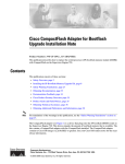
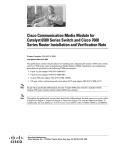
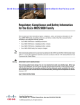
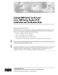
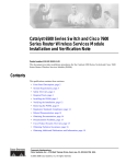
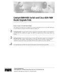
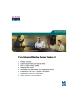
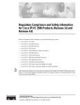
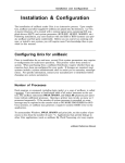
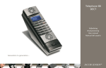
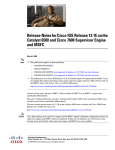
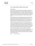
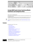
Catalyst 6500 Series Switch Content Switching
Module Installation Note
Product Number: WS-X6066-SLB-APC
This publication describes how to install the Content Switching Module (CSM) in the Catalyst 6500
series switches, including the software and hardware requirements.
Contents
This publication contains these sections:
•
Safety Overview, page 2
•
Front Panel Description, page 7
•
Environmental and System Requirements, page 9
•
Installing the CSM, page 11
•
Verifying the Installation, page 20
•
Using the CLI, page 20
•
Related Documentation, page 21
•
Translated Safety Warnings, page 21
•
Obtaining Documentation, page 24
•
Documentation Feedback, page 25
•
Obtaining Technical Assistance, page 25
•
Obtaining Additional Publications and Information, page 26
Corporate Headquarters:
Cisco Systems, Inc., 170 West Tasman Drive, San Jose, CA 95134-1706 USA
Copyright © 2004 Cisco Systems, Inc. All rights reserved.
Safety Overview
Safety Overview
Warning
IMPORTANT SAFETY INSTRUCTIONS
This warning symbol means danger. You are in a situation that could cause bodily injury. Before you
work on any equipment, be aware of the hazards involved with electrical circuitry and be familiar
with standard practices for preventing accidents. Use the statement number provided at the end of
each warning to locate its translation in the translated safety warnings that accompanied this
device. Statement 1071
SAVE THESE INSTRUCTIONS
Waarschuwing
BELANGRIJKE VEILIGHEIDSINSTRUCTIES
Dit waarschuwingssymbool betekent gevaar. U verkeert in een situatie die lichamelijk letsel kan
veroorzaken. Voordat u aan enige apparatuur gaat werken, dient u zich bewust te zijn van de bij
elektrische schakelingen betrokken risico's en dient u op de hoogte te zijn van de standaard
praktijken om ongelukken te voorkomen. Gebruik het nummer van de verklaring onderaan de
waarschuwing als u een vertaling van de waarschuwing die bij het apparaat wordt geleverd, wilt
raadplegen.
BEWAAR DEZE INSTRUCTIES
Varoitus
TÄRKEITÄ TURVALLISUUSOHJEITA
Tämä varoitusmerkki merkitsee vaaraa. Tilanne voi aiheuttaa ruumiillisia vammoja. Ennen kuin
käsittelet laitteistoa, huomioi sähköpiirien käsittelemiseen liittyvät riskit ja tutustu
onnettomuuksien yleisiin ehkäisytapoihin. Turvallisuusvaroitusten käännökset löytyvät laitteen
mukana toimitettujen käännettyjen turvallisuusvaroitusten joukosta varoitusten lopussa näkyvien
lausuntonumeroiden avulla.
SÄILYTÄ NÄMÄ OHJEET
Attention
IMPORTANTES INFORMATIONS DE SÉCURITÉ
Ce symbole d'avertissement indique un danger. Vous vous trouvez dans une situation pouvant
entraîner des blessures ou des dommages corporels. Avant de travailler sur un équipement, soyez
conscient des dangers liés aux circuits électriques et familiarisez-vous avec les procédures
couramment utilisées pour éviter les accidents. Pour prendre connaissance des traductions des
avertissements figurant dans les consignes de sécurité traduites qui accompagnent cet appareil,
référez-vous au numéro de l'instruction situé à la fin de chaque avertissement.
CONSERVEZ CES INFORMATIONS
Catalyst 6500 Series Switch Content Switching Module Installation Note
2
78-15751-03
Safety Overview
Warnung
WICHTIGE SICHERHEITSHINWEISE
Dieses Warnsymbol bedeutet Gefahr. Sie befinden sich in einer Situation, die zu Verletzungen führen
kann. Machen Sie sich vor der Arbeit mit Geräten mit den Gefahren elektrischer Schaltungen und
den üblichen Verfahren zur Vorbeugung vor Unfällen vertraut. Suchen Sie mit der am Ende jeder
Warnung angegebenen Anweisungsnummer nach der jeweiligen Übersetzung in den übersetzten
Sicherheitshinweisen, die zusammen mit diesem Gerät ausgeliefert wurden.
BEWAHREN SIE DIESE HINWEISE GUT AUF.
Avvertenza
IMPORTANTI ISTRUZIONI SULLA SICUREZZA
Questo simbolo di avvertenza indica un pericolo. La situazione potrebbe causare infortuni alle
persone. Prima di intervenire su qualsiasi apparecchiatura, occorre essere al corrente dei pericoli
relativi ai circuiti elettrici e conoscere le procedure standard per la prevenzione di incidenti.
Utilizzare il numero di istruzione presente alla fine di ciascuna avvertenza per individuare le
traduzioni delle avvertenze riportate in questo documento.
CONSERVARE QUESTE ISTRUZIONI
Advarsel
VIKTIGE SIKKERHETSINSTRUKSJONER
Dette advarselssymbolet betyr fare. Du er i en situasjon som kan føre til skade på person. Før du
begynner å arbeide med noe av utstyret, må du være oppmerksom på farene forbundet med
elektriske kretser, og kjenne til standardprosedyrer for å forhindre ulykker. Bruk nummeret i slutten
av hver advarsel for å finne oversettelsen i de oversatte sikkerhetsadvarslene som fulgte med denne
enheten.
TA VARE PÅ DISSE INSTRUKSJONENE
Aviso
INSTRUÇÕES IMPORTANTES DE SEGURANÇA
Este símbolo de aviso significa perigo. Você está em uma situação que poderá ser causadora de
lesões corporais. Antes de iniciar a utilização de qualquer equipamento, tenha conhecimento dos
perigos envolvidos no manuseio de circuitos elétricos e familiarize-se com as práticas habituais de
prevenção de acidentes. Utilize o número da instrução fornecido ao final de cada aviso para
localizar sua tradução nos avisos de segurança traduzidos que acompanham este dispositivo.
GUARDE ESTAS INSTRUÇÕES
¡Advertencia!
INSTRUCCIONES IMPORTANTES DE SEGURIDAD
Este símbolo de aviso indica peligro. Existe riesgo para su integridad física. Antes de manipular
cualquier equipo, considere los riesgos de la corriente eléctrica y familiarícese con los
procedimientos estándar de prevención de accidentes. Al final de cada advertencia encontrará el
número que le ayudará a encontrar el texto traducido en el apartado de traducciones que acompaña
a este dispositivo.
GUARDE ESTAS INSTRUCCIONES
Catalyst 6500 Series Switch Content Switching Module Installation Note
78-15751-03
3
Safety Overview
Varning!
VIKTIGA SÄKERHETSANVISNINGAR
Denna varningssignal signalerar fara. Du befinner dig i en situation som kan leda till personskada.
Innan du utför arbete på någon utrustning måste du vara medveten om farorna med elkretsar och
känna till vanliga förfaranden för att förebygga olyckor. Använd det nummer som finns i slutet av
varje varning för att hitta dess översättning i de översatta säkerhetsvarningar som medföljer denna
anordning.
SPARA DESSA ANVISNINGAR
Catalyst 6500 Series Switch Content Switching Module Installation Note
4
78-15751-03
Safety Overview
Aviso
INSTRUÇÕES IMPORTANTES DE SEGURANÇA
Este símbolo de aviso significa perigo. Você se encontra em uma situação em que há risco de lesões
corporais. Antes de trabalhar com qualquer equipamento, esteja ciente dos riscos que envolvem os
circuitos elétricos e familiarize-se com as práticas padrão de prevenção de acidentes. Use o
número da declaração fornecido ao final de cada aviso para localizar sua tradução nos avisos de
segurança traduzidos que acompanham o dispositivo.
GUARDE ESTAS INSTRUÇÕES
Advarsel
VIGTIGE SIKKERHEDSANVISNINGER
Dette advarselssymbol betyder fare. Du befinder dig i en situation med risiko for
legemesbeskadigelse. Før du begynder arbejde på udstyr, skal du være opmærksom på de
involverede risici, der er ved elektriske kredsløb, og du skal sætte dig ind i standardprocedurer til
undgåelse af ulykker. Brug erklæringsnummeret efter hver advarsel for at finde oversættelsen i de
oversatte advarsler, der fulgte med denne enhed.
GEM DISSE ANVISNINGER
Catalyst 6500 Series Switch Content Switching Module Installation Note
78-15751-03
5
Safety Overview
Catalyst 6500 Series Switch Content Switching Module Installation Note
6
78-15751-03
Front Panel Description
Front Panel Description
This section describes the physical attributes of the Content Switching Module .
Figure 1 shows the CSM front panel.
Content Switching Module Front Panel
CSM
Status
LED
Note
105789
Figure 1
RJ-45 (Test)
connector
The RJ-45 connector is covered by a removable plate.
Catalyst 6500 Series Switch Content Switching Module Installation Note
78-15751-03
7
Front Panel Description
Status LED
At startup, the CSM initializes various hardware components and communicates with the supervisor
engine. The Status LED indicates the supervisor engine operations and the initialization results. During
the normal initialization sequence, the status LED changes from off to red, orange, and green.
Note
For more information on the supervisor engine LEDs, refer to the Catalyst 6500 Series Switch Module
Installation Guide.
Table 1 describes the Status LED operation.
Table 1
Content Switching Module Status LED
Color
Off
Description
•
The module is waiting for the supervisor engine to provide power.
•
The module is not online.
•
The module is not receiving power, which could be caused by the following:
– Power is not available to the CSM.
– Module temperature is over the limit1.
Red
•
The module is released from reset by the supervisor engine and is booting.
•
If the boot code fails to run, the LED stays red after startup.
•
The module is initializing hardware or communicating with the supervisor
engine.
•
A fault occurred during the initialization sequence.
•
The module has failed to download its Field Programmable Gate Arrays
(FPGAs) at startup but continues with the remainder of the initialization
sequence and provides the module online status from the supervisor engine.
•
The module has not received module online status from the supervisor engine.
This problem could be caused by the supervisor engine detecting a failure in
an external loopback test that it issued to the CSM.
Green
•
The module is operational; the supervisor engine has provided module online
status.
Green to orange
•
The module is disabled through the supervisor engine CLI 2 using the set
module disable mod command.
Orange
1. Enter the show environment temperature mod command to display the temperature of each of four sensors on the CSM .
2. CLI=command-line interface.
RJ-45 Connector
The RJ-45 connector, which is covered by a removable plate, is used to connect a management station
device or a test device. This connector is used by field engineers to perform testing and to obtain dump
information.
Catalyst 6500 Series Switch Content Switching Module Installation Note
8
78-15751-03
Environmental and System Requirements
Environmental and System Requirements
This section describes the environmental and system requirements.
•
Environmental Requirements, page 9
•
System Requirements, page 9
•
Memory Requirements, page 9
•
Power Supply, page 10
•
Hardware Supported, page 10
•
Software Compatibility, page 10
Environmental Requirements
Table 2 lists the environmental requirements for the CSM.
Table 2
CSM Environmental Requirements
Item
Specification
Temperature, ambient operating
0o to 40oC (32o to 104oF)
Temperature, ambient nonoperating
–40o to 70oC (–40o to 158oF)
Humidity (RH), ambient (noncondensing)
operating
10% to 90%
Nonoperating relative humidity (noncondensing) 5% to 95%
System Requirements
Before you install the CSM in the Catalyst 6500 series switch, make sure that the switch meets the
hardware and software requirements listed in this section.
Caution
You can use the Multilayer Switch Feature Card (MSFC), which is internal to the Catalyst 6500 series
switch, to route traffic on either the client side or the server side of the CSM, but not both simultaneously
(unless policy-based routing is used).
Memory Requirements
The CSM memory is not configurable.
CSM software release 4.1(2) requires Cisco IOS software Release 12.1(8a)EX or higher. However, the
features new to CSM release 4.1(2) are available only with Cisco IOS Software Release 12.1(19) E and
Catalyst operating system software release 7.6 and higher.
Catalyst 6500 Series Switch Content Switching Module Installation Note
78-15751-03
9
Environmental and System Requirements
Power Supply
You can place the CSM in any slot in the Catalyst 6500 series chassis except for the slots that are
occupied by the supervisor engine and the standby supervisor engine. The CSM operates on power that
is supplied by the chassis.
Hardware Supported
Before you can use the Catalyst 6500 series CSM, you must have a Supervisor Engine 1A or a Supervisor
Engine 2 with a Multilayer Switch Feature Card (MSFC) or Multilayer Switch Feature Card 2 (MSFC2),
a Policy Feature Card (PFC), and a module with ports to connect server and client networks. The PFC
is required for the VLAN access control list (VACL) capture functionality.
Caution
The WS-X6066-SLB-APC module is not fabric enabled.
Product Number
Minimum Cisco Recommended
IOS Release
Cisco IOS Release
Recommended
Catalyst OS Releases
Content Switching Module
WS-X6066-SLB-APC with Supervisor Engine 1 and MSFC1 12.1(8a)EX
or MSFC2
12.1(13)E
N/A
Supervisor Engine 2 with MSFC2
12.1(8a)EX or
12.2(17d)SXB
12.1(13)E or higher
N/A
WS-X6066-SLB-APC with Supervisor Engine 720.
12.2(14)SX1
12.2(14)SX1 or
higher
N/A
Console Cable
72-876-01
Not applicable
Accessory Kit
800-05097-01
Not applicable
Software Compatibility
Software release 4.1(2) requires Cisco IOS Release 12.1(8a)EX or higher. However, the features new to
CSM release 4.1(2) are only available with Cisco IOS Release 12.1(19) E and Catalyst operating system
release 7.6 and subsequent releases.
Table 3 and Table 4 list the CSM software release compatibility.
The software release that is listed is the minimum required to support the CSM hardware with a given
supervisor engine to perform basic CSM configuration.
The recommended release is the base release to support new commands for a given CSM release.
Catalyst 6500 Series Switch Content Switching Module Installation Note
10
78-15751-03
Installing the CSM
Table 3
CSM with Cisco IOS Software Requirements
CSM Release
Supervisor Engine 1 MSFC1 or MSFC2 Supervisor Engine 2 with MSFC2
Supervisor 720 with MSFC 3
Minimum Software
Release
Recommended
Software Release
Minimum
Software Release
Recommended
Software Release
Minimum
Software Release
Recommended
Software Release
4.1(2)
12.1(8a)EX
12.1(19)E
12.1(8a)EX or
12.2(17d)SXB
12.1(19E
12.2(14)SX1
12.2(14)SX1
4.1(1)1
12.1(8a)EX
12.1(19)E
12.1(8a)EX or
12.2(17d)SXB
12.1(19)E
12.2(14)SX1
12.2(14)SX1
1. Back end encryption requires Cisco IOS software release 12.2(17d)SXB for the Supervisor Engine 2 or 12.2(17d)SXA for Supervisor Enging 720.
Table 4
CSM with Cisco IOS and Catalyst Operating System Software Requirements
CSM Release
Supervisor Engine 1 MSFC1 or MSFC2
Supervisor Engine 2 with MSFC2
Supervisor Engine 720 with MSFC 3
Minimum Software
Release
Recommended
Software Release
Minimum
Software Release
Recommended
Software Release
Minimum Software
Release
Recommended
Software Release
4.1(2)
Cisco IOS
12.1(13)E3 with
Catalyst
operating system
7.5
Cisco IOS
12.1(19)E with
Catalyst operating
system 7.5
Cisco IOS
12.1(13)E3 with
Catalyst
operating
system 7.5
Cisco IOS
12.1(19)E with
Catalyst
operating
system 7.5
Cisco IOS
12.2(14)SX2
with Catalyst
operating system
8.2(1)
Cisco IOS
12.2(17d)SX1
with Catalyst
operating system
8.2(1)
4.1(1)1
Cisco IOS
12.1(13)E3 with
Catalyst
operating system
7.5
Cisco IOS
12.1(19)E with
Catalyst operating
system 7.5
Cisco IOS
12.1(13)E3 with
Catalyst
operating
system 7.5
Cisco IOS
12.1(19)E with
Catalyst
operating
system 7.5
Cisco IOS
12.2(14)SX2
with Catalyst
operating system
8.2(1)
Cisco IOS
12.2(17d)SX1
with Catalyst
operating system
8.2(1)
1. Back end encryption requires Cisco IOS software release 12.2(17d)SXB for the Supervisor Engine 2 or 12.2(17d)SXA for Supervisor Enging 720.
Installing the CSM
These sections describe how to install the CSM:
Caution
•
Preparing to Install the CSM, page 11
•
Required Tools, page 12
•
Installing and Removing the Module, page 12
The WS-X6066-SLB-APC Content Switching Module is not fabric enabled.
Preparing to Install the CSM
Before installing the CSM, make sure that the following items are available:
•
Catalyst 6500 series switch chassis
•
Management station that is available through a Telnet or a console connection to perform
configuration tasks
Catalyst 6500 Series Switch Content Switching Module Installation Note
78-15751-03
11
Installing the CSM
Required Tools
These tools are required to install the CSM in the Catalyst 6500 series switches:
•
Flat-blade screwdriver
•
Phillips-head screwdriver
•
Wrist strap or other grounding device
•
Antistatic mat or antistatic foam
Whenever you handle the CSM, always use a wrist strap or other grounding device to prevent
electrostatic discharge (ESD).
Installing and Removing the Module
Caution
During this procedure, wear grounding wrist straps to avoid ESD damage to the module. Do not directly
touch the backplane with your hand or any metal tool, or you could shock yourself.
All Catalyst 6500 series switches support hot swapping, which allows you to install, remove, replace,
and rearrange modules without turning off the system power. For more information on removing the
CSM from a switch, see the “Removing the Module” section on page 13.
When the system detects that a module has been installed or removed, the system automatically runs
diagnostic and discovery routines, acknowledges the presence or absence of the module, and resumes
system operation.
These sections describe how to install and verify the operation of the CSM in the Catalyst 6500 series
switches:
•
Slot Assignments, page 12
•
Removing the Module, page 13
•
Installing a Module, page 14
Slot Assignments
The Catalyst 6006 and 6506 switch chassis have 6 slots, the Catalyst 6009 and 6509 switch chassis have
9 slots, and the Catalyst 6513 switch chassis has 13 slots.
Note
The Catalyst 6509-NEB switch has vertical slots, which are numbered 1 to 9 from right to left. Install
the modules with the component side facing to the right.
•
Slot 1 is reserved for the supervisor engine.
•
Slot 2 can be used for a redundant supervisor engine if the supervisor engine in slot 1 fails.
•
If a redundant supervisor engine is not required, slots 2 through 6 on the 6-slot chassis, slots 2
through 9 on the 9-slot chassis, and slots 2 through 13 on the 13-slot chassis are available for
switching modules, such as the CSM.
•
The empty slots require filler plates, which are blank switching-module carriers that maintain
consistent airflow through the switch chassis.
Catalyst 6500 Series Switch Content Switching Module Installation Note
12
78-15751-03
Installing the CSM
Removing the Module
This section describes how to remove an existing module from a Catalyst 6500 series switch chassis slot.
Caution
Warning
During this procedure, wear grounding wrist straps to avoid ESD damage to the module. Do not directly
touch the backplane with your hand or any metal tool, or you could shock yourself.
Invisible laser radiation may be emitted from disconnected fibers or connectors. Do not stare into
beams or view directly with optical instruments.
To remove a supervisor engine or module from the chassis, perform these steps:
Step 1
Disconnect any network interface cables that are attached to the supervisor engine or module.
Step 2
Verify that the captive installation screws on all of the modules in the chassis are tight.
This step assures that the space that is created by the removed module is maintained.
Note
If the captive installation screws are loose, the electromagnetic interference (EMI) gaskets on
the installed modules will push the modules toward the open slot, reducing the opening size and
making it difficult to install the replacement module.
Step 3
Loosen the two captive installation screws on the supervisor engine or module.
Step 4
Depending on the orientation of the slots in the chassis (horizontal or vertical), perform one of the
following sets of substeps:
Horizontal slots
a.
Place your thumbs on the left and right ejector levers, and simultaneously rotate the levers outward
to unseat the module from the backplane connector.
b.
Grasp the front edge of the module, and slide the module part of the way out of the slot. Place your
other hand under the module to support the weight of the module. Do not touch the module circuitry.
Vertical slots
a.
Place your thumbs on the ejector levers that are located at the top and bottom of the module, and
simultaneously rotate the levers outward to unseat the module from the backplane connector.
b.
Grasp the edges of the module, and slide the module straight out of the slot. Do not touch the module
circuitry.
Step 5
Place the module on an antistatic mat or antistatic foam, or immediately reinstall it in another slot.
Step 6
If the slot from which you removed the module is to remain empty, install a module filler plate to keep
dust out of the chassis and to maintain proper airflow through the chassis.
Catalyst 6500 Series Switch Content Switching Module Installation Note
78-15751-03
13
Installing the CSM
Warning
Blank faceplates (filler panels) serve three important functions: they prevent exposure to hazardous
voltages and currents inside the chassis; they contain electromagnetic interference (EMI) that might
disrupt other equipment; and they direct the flow of cooling air through the chassis. Do not operate
the system unless all cards and faceplates are in place.
Installing a Module
This section describes how to install a supervisor engine or module in the Catalyst 6500 series switches.
Caution
To prevent ESD damage, handle modules by the carrier edges only.
Caution
During this procedure, wear grounding wrist straps to avoid ESD damage to the module. Do not directly
touch the backplane with your hand or any metal tool, or you could shock yourself.
Warning
Invisible laser radiation may be emitted from disconnected fibers or connectors. Do not stare into
beams or view directly with optical instruments.
To install a supervisor engine or module in the chassis, perform these steps:
Step 1
Choose a slot for the supervisor engine or module.
Step 2
Verify that there is enough clearance to accommodate any interface equipment that you will connect
directly to the supervisor engine or module ports. If possible, place modules between empty slots that
contain only module filler plates.
Step 3
Verify that the captive installation screws are tightened on all modules installed in the chassis.
This action ensures that the EMI gaskets on all modules are fully compressed to maximize the opening
space for the replacement module.
Note
If the captive installation screws are loose, the EMI gaskets on the installed modules will push
adjacent modules toward the open slot, reducing the opening size and making it difficult to
install the replacement module.
Step 4
Remove the module filler plate by removing the two Phillips pan-head screws from the filler plate. (To
remove a module, refer to the “Removing the Module” section on page 13.)
Step 5
Fully open both ejector levers on the new or replacement module. (See Figure 2.)
Catalyst 6500 Series Switch Content Switching Module Installation Note
14
78-15751-03
Installing the CSM
Figure 2
Positioning the Module in a Horizontal Slot Chassis
Insert module
between slot guides
EMI gasket
3
4
5
6
4
5
6
WS-X6K-SUP2-2GE
1
ST
AT
US
SY
ST
OL
EM
T
E
NS
CO
R
M
PW
GM
SE
Switch
100%
T
Load
CONSOLE
PORT
MODE
RE
PORT 1
PORT 2
CONSOLE
SUPERVISOR2
PCMCIA
EJECT
1%
WS-X6K-SUP2-2GE
2
ST
AT
US
SY
ST
OL
EM
CO
T
E
NS
R
PW
M
GM
SE
Switch
100%
T
Load
CONSOLE
PORT
MODE
RE
PORT 1
PORT 2
CONSOLE
SUPERVISOR2
PCMCIA
EJECT
1%
3
4
FAN
STATUS 5
6
WS-X6224
AT
US
VE
AC
TI
SE
LE
24 PORT 100FX
NE
EMI gasket
CT
XT
58569
ST
o
o
INPUT
OK
FAN
OK
OUTPUT
FAIL
INPUT
OK
FAN
OK
OUTPUT
FAIL
WS-C6500-SFM
US
AT
ST
E
TIV
AC
SWITCH FABRIC MDL
Ejector lever fully
extended
Step 6
Depending on the orientation of the slots in the chassis (horizontal or vertical), perform one of the
following sets of substeps:
Horizontal slots
a.
Position the supervisor engine or module in the slot. Make sure that you align the sides of the module
carrier with the slot guides on each side of the slot. (See Figure 2.)
b.
Carefully slide the supervisor engine or module into the slot until the EMI gasket along the top edge
of the module makes contact with the module in the slot above it and both ejector levers have closed
to approximately 45 degrees with respect to the module faceplate. (See Figure 3.)
Catalyst 6500 Series Switch Content Switching Module Installation Note
78-15751-03
15
Installing the CSM
Figure 3
Clearing the EMI Gasket in a Horizontal Slot Chassis
WS-X6K-SUP2-2GE
T
M
LE
G
O
US
EM
M
T
AT
NS
R
ST
SE
ST
SY
CO
PW
RE
1
Switch
100%
CONSOLE
Load
CONSOLE
PORT
MODE
SUPERVISOR2
PORT 1
PCMCIA
PORT 2
EJECT
1%
WS-X6K-SUP2-2GE
NK
LI
T
M
LE
G
O
US
EM
M
T
AT
NS
R
ST
SE
ST
SY
CO
PW
RE
2
Switch
100%
CONSOLE
SUPERVISOR2
CONSOLE
PORT
MODE
PORT 1
PCMCIA
NK
LI
Load
PORT 2
EJECT
1%
NK
LI
NK
LI
3
Press down
4
FAN
STATUS 5
Press down
WS-X6224
S
TU
STA
VE
TI
AC
CT
LE
SE
24 PORT 100FX
XT
NE
6
3
4
WS-C6500-SFM
5
5
SWITCH FABIR
6
c.
Caution
ST
AT
US
AC
TIV
E
D MDL
1 mm Gap between the module
EMI gasket and the
module above it
6
58570
4
Using the thumb and forefinger of each hand, grasp the two ejector levers and press down to create
a small (0.040 inch [1 mm]) gap between the EMI gasket and the module above it. (See Figure 3.)
Pressing down too firmly on the levers will bend and damage them.
d.
While pressing down, simultaneously close the left and right ejector levers to fully seat the
supervisor engine or module in the backplane connector. The ejector levers are fully closed when
they are flush with the module faceplate. (See Figure 4.)
Catalyst 6500 Series Switch Content Switching Module Installation Note
16
78-15751-03
Installing the CSM
Figure 4
Ejector Lever Closure in a Horizontal Slot Chassis
WS-X6K-SUP2-2GE
T
M
LE
G
O
US
EM
M
T
AT
NS
R
ST
SE
ST
SY
CO
PW
RE
1
Switch
100%
CONSOLE
SUPERVISOR2
Load
CONSOLE
PORT
MODE
PORT 1
PCMCIA
PORT 2
EJECT
1%
WS-X6K-SUP2-2GE
NK
LI
T
M
LE
G
O
US
EM
M
T
AT
NS
R
ST
SE
ST
SY
CO
PW
RE
2
Switch
100%
CONSOLE
SUPERVISOR2
PORT 1
PCMCIA
NK
LI
Load
CONSOLE
PORT
MODE
PORT 2
EJECT
1%
NK
LI
NK
LI
3
4
FAN
STATUS 5
WS-C6500-SFM
S
TU
STA
SWITCH FABRIC MDL
VE
TI
AC
CT
LE
SE
XT
NE
58571
6
Ejector levers flush
with module faceplate
Note
e.
Failure to fully seat the module in the backplane connector can result in error messages.
Tighten the two captive installation screws on the supervisor engine or module.
Note
Make sure that the ejector levers are fully closed before tightening the captive installation
screws.
Vertical slots
a.
Position the supervisor engine or switching module in the slot. (See Figure 5.) Make sure that you
align the sides of the switching-module carrier with the slot guides on the top and bottom of the slot.
Catalyst 6500 Series Switch Content Switching Module Installation Note
78-15751-03
17
Installing the CSM
Figure 5
Positioning the Module in a Vertical Slot Chassis
Ejector lever fully
extended
WS-C6500-SFM
SWITCH FABRIC MDL
FAN
STATUS
WS-X6K-SUP2-2GE
TUS
SYS
MT
OLE MG
TEM NS
R
SET
RE
PW
CO
MT
E
M
S
OL
T
MG
TU
R
NS
SE
STE
RE
PW
CO
SY
STA
STA
WS-X6K-SUP2-2GE
SUPERVISOR2
SUPERVISOR2
ST
AT
CONSOLE
CONSOLE
AC
US
PORT
MODE
PORT
MODE
CONSOLE
WS-X6224
24 PORT 100FX
CONSOLE
TIV
E
ST
AT
US
AC
TIV
E
PCMCIA
PCMCIA
EJECT
EJECT
Switch
Switch
1%
100%
1%
100%
Load
Load
PORT 1
PORT 1
PORT 2
PORT 2
NE
XT
EMI
gasket
SE
LE
CT
63585
EMI
gasket
o
o
INPUT
OK
FAN
OK
OUTPUT
FAIL
INPUT
OK
FAN
OK
OUTPUT
FAIL
6
Insert module
between slot guides
3
4
b.
Carefully slide the supervisor engine or module into the slot until the EMI gasket along the right
edge of the module makes contact with the module in the slot adjacent to it and both ejector levers
have closed to approximately 45 degrees with respect to the module faceplate. (See Figure 6.)
c.
Using the thumb and forefinger of each hand, grasp the two ejector levers and exert a slight pressure
to the left, deflecting the module approximately 0.040 inches (1 mm) to create a small gap between
the modules EMI gasket and the module adjacent to it. (See Figure 6.)
Catalyst 6500 Series Switch Content Switching Module Installation Note
18
78-15751-03
Installing the CSM
Figure 6
Clearing the EMI Gasket in a Vertical Slot Chassis
Gap between the module
EMI gasket and the
module above it
1 mm
WS-C6500-SFM
SWITCH FABIRD MDL
US
AT
ST
E
TIV
AC
FAN
STATUS
WS-X6K-SUP2-2GE
STA
TUS
SYS
AT
US
MT
OLE MG
TEM NS
R
SET
RE
PW
CO
ST
MT
E
M
S
OL
T
MG
TU
R
NS
SE
STE
RE
PW
CO
SY
STA
WS-X6K-SUP2-2GE
SUPERVISOR2
SUPERVISOR2
WS-X6224
24 PORT 100FX
AC
E
CONSOLE
CONSOLE
TIV
PORT
CONSOLE
PORT
MODE
MODE
CONSOLE
Press left
PCMCIA
PCMCIA
EJECT
EJECT
Switch
Switch
1%
100%
1%
100%
Load
Load
NE
XT
SE
LE
PORT 1
PORT 1
Press left
CT
63586
PORT 2
PORT 2
o
o
INPUT
OK
FAN
OK
OUTPUT
FAIL
INPUT
OK
Caution
FAN
OK
OUTPUT
FAIL
Exerting too much pressure on the ejector levers will bend and damage them.
d.
While pressing on the ejector levers, simultaneously close them to fully seat the supervisor engine
or module in the backplane connector. The ejector levers are fully closed when they are flush with
the module faceplate. (See Figure 7.)
Catalyst 6500 Series Switch Content Switching Module Installation Note
78-15751-03
19
Verifying the Installation
Figure 7
Ejector Lever Closure in a Vertical Slot Chassis
FAN
STATUS
ST
WS-X6K-SUP2-2GE
SUPERVISOR2
AT
US
SY
ST
CO
EM
NS
O
PW
LE
R
M
M
RE
G
SE
T
S
TU
STA
T
M
LE
G
O
T
M
EM
US
R
NS
SE
ST
AT
RE
PW
CO
SY
ST
WS-X6K-SUP2-2GE
SUPERVISOR2
WS-X6224
24 PORT 100FX
T
CONSOLE
CONSOLE
VE
TI
AC
CONSOLE
PORT
MODE
CONSOLE
PORT
MODE
PCMCIA
PCMCIA
EJECT
EJECT
1%
Switch
Switch
100%
1%
100%
SE
LE
PORT 1
PORT 1
XT
Load
Load
NE
CT
63587
PORT 2
PORT 2
All ejector levers flush
with module faceplate
e.
Tighten the two captive installation screws on the module.
Note
Make sure that the ejector levers are fully closed before tightening the captive installation
screws.
This completes the CSM installation procedure.
Verifying the Installation
When you install the CSM in a Catalyst 6500 series switch, the module goes through a startup sequence
that requires no intervention. At the successful conclusion of the startup sequence, the green Status LED
will light and remain on. If the Status LED does not show green, or if it shows a different color, refer to
Table 1 on page 8 to determine the modules status.
Using the CLI
The software interface for the module is the Cisco IOS and the Catalyst operating system command-line
interface accessed through a Telnet connection to the switch or through the switch console interface.
Refer to the Catalyst 6500 Series Switch Cisco IOS Software Configuration Guide and the Catalyst 6500
Series Switch Software Configuration Guide for details.
Catalyst 6500 Series Switch Content Switching Module Installation Note
20
78-15751-03
Related Documentation
To understand the Cisco IOS command-line interface and Cisco IOS command modes, refer to
Chapter 2, “Command-Line Interfaces,” in the Catalyst 6500 Series Switch Cisco IOS Software
Configuration Guide.
To understand the Catalyst operating system command-line interface and Catalyst operating system
command modes, refer to Chapter 2, “Command-Line Interfaces,” in the Catalyst 6500 Series Switch
Configuration Guide.
Unless your switch is located in a fully trusted environment, we recommend that you configure the
module through a Telnet connection using Secure Shell (SSH) encryption.
You can session into the module from the switch console to configure the CSM. The session is a Telnet
interface through the Ethernet out-of-band channel (EOBC) of the switch backplane.
You can also make a Telnet connection into the module from a specified host and on a specific interface.
Telnet support for this host should be configured or enabled from the module console.
Console output is redirected to all active Telnet sessions. When no Telnet session is available, the output
is saved to a buffer. The buffer output can be subsequently examined when you make a Telnet connection
into the module.
Related Documentation
Use this document with the following Cisco documents:
•
Catalyst 6500 Series Switch Cisco IOS Software Configuration Guide
•
Catalyst 6500 Series Switch Software Configuration Guide
•
Catalyst 6500 Series Switch Content Switching Module Command Reference Release 4.1
•
Catalyst 6500 Series Switch Content Switching Module Installation Guide Release 4.1
•
Catalyst 6500 Series Switch Content Switching Module and Installation and Configuration Guide
Release 4.1
•
Release Notes for the Catalyst 6500 Series Switch Content Switching Module Release 4.1.
Translated Safety Warnings
Warning
Waarschuwing
Varoitus
Invisible laser radiation present. Statement 1016
Onzichtbare laserstraling aanwezig.
Näkymättömiä lasersäteitä.
Attention
Rayonnement laser actif mais invisible.
Warnung
Unsichtbare Laserstrahlung.
Avvertenza
Radiazione laser invisibile.
Catalyst 6500 Series Switch Content Switching Module Installation Note
78-15751-03
21
Translated Safety Warnings
Advarsel
Aviso
¡Advertencia!
Usynlig laserstråling.
Radiação laser invisível presente.
Existe radiación láser invisible.
Varning!
Nu pågående osynlig laserstrålning.
Warning
Blank faceplates and cover panels serve three important functions: they prevent exposure to
hazardous voltages and currents inside the chassis; they contain electromagnetic interference
(EMI) that might disrupt other equipment; and they direct the flow of cooling air through the chassis.
Do not operate the system unless all cards, faceplates, front covers, and rear covers are in place.
Statement 1029
Waarschuwing
Lege vlakplaten en afdekpanelen vervullen drie belangrijke functies: ze voorkomen blootstelling
aan gevaarlijke voltages en stroom binnenin het frame, ze bevatten elektromagnetische storing
(EMI) hetgeen andere apparaten kan verstoren en ze leiden de stroom van koellucht door het frame.
Het systeem niet bedienen tenzij alle kaarten, vlakplaten en afdekkingen aan de voor- en achterkant
zich op hun plaats bevinden.
Varoitus
Tyhjillä tasolaikoilla ja suojapaneeleilla on kolme tärkeää käyttötarkoitusta: Ne suojaavat
asennuspohjan sisäisille vaarallisille jännitteille ja sähkövirralle altistumiselta; ne pitävät
sisällään elektromagneettisen häiriön (EMI), joka voi häiritä muita laitteita; ja ne suuntaavat
tuuletusilman asennuspohjan läpi. Järjestelmää ei saa käyttää, elleivät kaikki tasolaikat, etukannet
ja takakannet ole kunnolla paikoillaan.
Attention
Ne jamais faire fonctionner le système sans que l’intégralité des cartes, des plaques métalliques et
des panneaux avant et arrière ne soient fixés à leur emplacement. Ceux-ci remplissent trois
fonctions essentielles : ils évitent tout risque de contact avec des tensions et des courants
dangereux à l’intérieur du châssis, ils évitent toute diffusion d’interférences électromagnétiques
qui pourraient perturber le fonctionnement des autres équipements, et ils canalisent le flux d’air de
refroidissement dans le châssis.
Catalyst 6500 Series Switch Content Switching Module Installation Note
22
78-15751-03
Translated Safety Warnings
Warnung
Blanke Faceplates und Abdeckungen haben drei wichtigen Funktionen: (1) Sie schützen vor
gefährlichen Spannungen und Strom innerhalb des Chassis; (2) sie halten elektromagnetische
Interferenzen (EMI) zurück, die andere Geräte stören könnten; (3) sie lenken den kühlenden
Luftstrom durch das Chassis. Das System darf nur betrieben werden, wenn alle Karten, Faceplates,
Voder- und Rückabdeckungen an Ort und Stelle sind.
Avvertenza
Le piattaforme bianche e i panelli di protezione hanno tre funzioni importanti: Evitano l'esposizione
a voltaggi e correnti elettriche pericolose nello chassis, trattengono le interferenze
elettromagnetiche (EMI) che potrebbero scombussolare altri apparati e dirigono il flusso di aria per
il raffreddamento attraverso lo chassis. Non mettete in funzione il sistema se le schede, le
piattaforme, i panelli frontali e posteriori non sono in posizione.
Advarsel
Blanke ytterplater og deksler sørger for tre viktige funksjoner: de forhindrer utsettelse for farlig
spenning og strøm inni kabinettet; de inneholder elektromagnetisk forstyrrelse (EMI) som kan
avbryte annet utstyr, og de dirigerer luftavkjølingsstrømmen gjennom kabinettet. Betjen ikke
systemet med mindre alle kort, ytterplater, frontdeksler og bakdeksler sitter på plass.
Aviso
As faces furadas e os painéis de protecção desempenham três importantes funções: previnem
contra uma exposição perigosa a voltagens e correntes existentes no interior do chassis; previnem
contra interferência electromagnética (EMI) que poderá danificar outro equipamento; e canalizam
o fluxo do ar de refrigeração através do chassis. Não deverá operar o sistema sem que todas as
placas, faces, protecções anteriores e posteriores estejam nos seus lugares.
¡Advertencia!
Las placas frontales y los paneles de relleno cumplen tres funciones importantes: evitan la
exposición a niveles peligrosos de voltaje y corriente dentro del chasis; reducen la interferencia
electromagnética (EMI) que podría perturbar la operación de otros equipos y dirigen el flujo de aire
de enfriamiento a través del chasis. No haga funcionar el sistema a menos que todas las tarjetas,
placas frontales, cubiertas frontales y cubiertas traseras estén en su lugar.
Varning!
Tomma framplattor och skyddspaneler har tre viktiga funktioner: de förhindrar att personer utsätts
för farlig spänning och ström som finns inuti chassit; de innehåller elektromagnetisk interferens
(EMI) som kan störa annan utrustning; och de styr riktningen på kylluftsflödet genom chassit. Använd
inte systemet om inte alla kort, framplattor, fram- och bakskydd är på plats.
Catalyst 6500 Series Switch Content Switching Module Installation Note
78-15751-03
23
Obtaining Documentation
Obtaining Documentation
Cisco documentation and additional literature are available on Cisco.com. Cisco also provides several
ways to obtain technical assistance and other technical resources. These sections explain how to obtain
technical information from Cisco Systems.
Cisco.com
You can access the most current Cisco documentation at this URL:
http://www.cisco.com/univercd/home/home.htm
You can access the Cisco website at this URL:
http://www.cisco.com
You can access international Cisco websites at this URL:
http://www.cisco.com/public/countries_languages.shtml
Ordering Documentation
You can find instructions for ordering documentation at this URL:
http://www.cisco.com/univercd/cc/td/doc/es_inpck/pdi.htm
You can order Cisco documentation in these ways:
•
Registered Cisco.com users (Cisco direct customers) can order Cisco product documentation from
the Ordering tool:
http://www.cisco.com/en/US/partner/ordering/index.shtml
•
Nonregistered Cisco.com users can order documentation through a local account representative by
calling Cisco Systems Corporate Headquarters (California, USA) at 408 526-7208 or, elsewhere in
North America, by calling 800 553-NETS (6387).
Catalyst 6500 Series Switch Content Switching Module Installation Note
24
78-15751-03
Documentation Feedback
Documentation Feedback
You can send comments about technical documentation to [email protected].
You can submit comments by using the response module (if present) behind the front cover of your
document or by writing to the following address:
Cisco Systems
Attn: Customer Document Ordering
170 West Tasman Drive
San Jose, CA 95134-9883
We appreciate your comments.
Obtaining Technical Assistance
For all customers, partners, resellers, and distributors who hold valid Cisco service contracts, Cisco
Technical Support provides 24-hour-a-day, award-winning technical assistance. The Cisco Technical
Support Website on Cisco.com features extensive online support resources. In addition, Cisco Technical
Assistance Center (TAC) engineers provide telephone support. If you do not hold a valid Cisco service
contract, contact your reseller.
Cisco Technical Support Website
The Cisco Technical Support Website provides online documents and tools for troubleshooting and
resolving technical issues with Cisco products and technologies. The website is available 24 hours a day,
365 days a year at this URL:
http://www.cisco.com/techsupport
Access to all tools on the Cisco Technical Support Website requires a Cisco.com user ID and password.
If you have a valid service contract but do not have a user ID or password, you can register at this URL:
http://tools.cisco.com/RPF/register/register.do
Submitting a Service Request
Using the online TAC Service Request Tool is the fastest way to open S3 and S4 service requests. (S3
and S4 service requests are those in which your network is minimally impaired or for which you require
product information.) After you describe your situation, the TAC Service Request Tool automatically
provides recommended solutions. If your issue is not resolved using the recommended resources, your
service request will be assigned to a Cisco TAC engineer. The TAC Service Request Tool is located at
this URL:
http://www.cisco.com/techsupport/servicerequest
For S1 or S2 service requests or if you do not have Internet access, contact the Cisco TAC by telephone.
(S1 or S2 service requests are those in which your production network is down or severely degraded.)
Cisco TAC engineers are assigned immediately to S1 and S2 service requests to help keep your business
operations running smoothly.
Catalyst 6500 Series Switch Content Switching Module Installation Note
78-15751-03
25
Obtaining Additional Publications and Information
To open a service request by telephone, use one of the following numbers:
Asia-Pacific: +61 2 8446 7411 (Australia: 1 800 805 227)
EMEA: +32 2 704 55 55
USA: 1 800 553 2447
For a complete list of Cisco TAC contacts, go to this URL:
http://www.cisco.com/techsupport/contacts
Definitions of Service Request Severity
To ensure that all service requests are reported in a standard format, Cisco has established severity
definitions.
Severity 1 (S1)—Your network is “down,” or there is a critical impact to your business operations. You
and Cisco will commit all necessary resources around the clock to resolve the situation.
Severity 2 (S2)—Operation of an existing network is severely degraded, or significant aspects of your
business operation are negatively affected by inadequate performance of Cisco products. You and Cisco
will commit full-time resources during normal business hours to resolve the situation.
Severity 3 (S3)—Operational performance of your network is impaired, but most business operations
remain functional. You and Cisco will commit resources during normal business hours to restore service
to satisfactory levels.
Severity 4 (S4)—You require information or assistance with Cisco product capabilities, installation, or
configuration. There is little or no effect on your business operations.
Obtaining Additional Publications and Information
Information about Cisco products, technologies, and network solutions is available from various online
and printed sources.
•
Cisco Marketplace provides a variety of Cisco books, reference guides, and logo merchandise. Visit
Cisco Marketplace, the company store, at this URL:
http://www.cisco.com/go/marketplace/
•
The Cisco Product Catalog describes the networking products offered by Cisco Systems, as well as
ordering and customer support services. Access the Cisco Product Catalog at this URL:
http://cisco.com/univercd/cc/td/doc/pcat/
•
Cisco Press publishes a wide range of general networking, training and certification titles. Both new
and experienced users will benefit from these publications. For current Cisco Press titles and other
information, go to Cisco Press at this URL:
http://www.ciscopress.com
•
Packet magazine is the Cisco Systems technical user magazine for maximizing Internet and
networking investments. Each quarter, Packet delivers coverage of the latest industry trends,
technology breakthroughs, and Cisco products and solutions, as well as network deployment and
troubleshooting tips, configuration examples, customer case studies, certification and training
information, and links to scores of in-depth online resources. You can access Packet magazine at this
URL:
http://www.cisco.com/packet
Catalyst 6500 Series Switch Content Switching Module Installation Note
26
78-15751-03
Obtaining Additional Publications and Information
•
iQ Magazine is the quarterly publication from Cisco Systems designed to help growing companies
learn how they can use technology to increase revenue, streamline their business, and expand
services. The publication identifies the challenges facing these companies and the technologies to
help solve them, using real-world case studies and business strategies to help readers make sound
technology investment decisions. You can access iQ Magazine at this URL:
http://www.cisco.com/go/iqmagazine
•
Internet Protocol Journal is a quarterly journal published by Cisco Systems for engineering
professionals involved in designing, developing, and operating public and private internets and
intranets. You can access the Internet Protocol Journal at this URL:
http://www.cisco.com/ipj
•
World-class networking training is available from Cisco. You can view current offerings at
this URL:
http://www.cisco.com/en/US/learning/index.html
Catalyst 6500 Series Switch Content Switching Module Installation Note
78-15751-03
27
Obtaining Additional Publications and Information
This document is to be used in conjunction with the documents listed in the “Related Documentation” section.
Copyright © 2004 Cisco Systems, Inc. All rights reserved.
Catalyst 6500 Series Switch Content Switching Module Installation Note
28
78-15751-03