1
Guide
Cisco Catalyst 3850 Switch
Services Guide
April 2013
© 2013 Cisco and/or its affiliates. All rights reserved. This document is Cisco Public Information.
Page 1 of 70
Contents
Overview ................................................................................................................................................................... 3
Cisco Catalyst 3850 Security Policy....................................................................................................................... 3
Configuring 802.1X in Converged Access ............................................................................................................. 3
802.1X Configuration for Wired Users .................................................................................................................. 5
802.1X Configuration for Wireless Users .............................................................................................................. 6
Downloadable Access Control List ........................................................................................................................ 8
Access Control List Deployment Considerations .................................................................................................. 9
Cisco Catalyst 3850 Quality of Service ................................................................................................................ 10
Wired Quality of Service...................................................................................................................................... 10
Cisco Catalyst 3850 Trust Behavior ............................................................................................................... 10
Configuring Ingress Quality of Service ........................................................................................................... 11
Egress Quality of Service ............................................................................................................................... 14
Wireless Quality of Service ................................................................................................................................. 15
Wireless Targets ................................................................................................................................................. 15
Wireless: Ingress Quality of Service ................................................................................................................... 16
Ingress Marking and Policing on Wireless Client............................................................................................ 16
Ingress Policies on WLAN/SSID..................................................................................................................... 18
Wireless: Egress Quality of Service .................................................................................................................... 19
Policy on Access Point/Port ........................................................................................................................... 19
Policy on Radio .............................................................................................................................................. 21
Policy on Service Set Identification ................................................................................................................ 22
Client .............................................................................................................................................................. 23
Flexible NetFlow .................................................................................................................................................... 23
Cisco Catalyst 3850 NetFlow Architecture (Wired and Wireless) ........................................................................ 24
NetFlow Cisco Catalyst 3850 Overview .............................................................................................................. 24
NetFlow Configuration on Cisco Catalyst 3850 Switch ....................................................................................... 24
Flow Record ................................................................................................................................................... 24
Exporter/Collector Information ........................................................................................................................ 25
Flow Monitor ................................................................................................................................................... 25
Attaching a Flow Monitor to Supported Port Types ............................................................................................. 26
Flexible NetFlow Outputs .................................................................................................................................... 27
Multicast Overview (Traditional and Converged Multicast) ................................................................................. 30
Restrictions of IP Multicast Routing Configuration .............................................................................................. 30
Configuring Wireless IP Multicast on Cisco Catalyst 3850 .................................................................................. 30
Multicast Mode Configuration.............................................................................................................................. 31
Multicast Show Commands................................................................................................................................. 32
Converged Access with the Cisco Catalyst 3850 ............................................................................................... 37
Distributed Functions Enabling Converged Access ........................................................................................ 37
Logical Hierarchical Groupings of Roles ........................................................................................................ 38
Converged Access Network Design with Cisco Catalyst 3850 .......................................................................... 39
Configuring Converged Access with Cisco Catalyst 3850 ................................................................................. 42
Roaming in Cisco Unified Wireless Network ....................................................................................................... 49
Understanding Roams in Converged Access ..................................................................................................... 52
Traffic Paths in Converged Access ...................................................................................................................... 54
Relevant Outputs for Tracking Client Roams in Converged Access ................................................................ 55
Nontunneled Roam in Converged Access ........................................................................................................... 64
Tunnel Roles in Converged Access ..................................................................................................................... 67
Appendix A: Detailed FnF Field Support ............................................................................................................. 68
© 2013 Cisco and/or its affiliates. All rights reserved. This document is Cisco Public Information.
Page 2 of 70
Overview
®
®
The Cisco Catalyst 3850 Switch is built on a unified access data plane (UADP) application-specific integrated
circuit (ASIC). This is a state-of-the-art ASIC that has all services fully integrated in the chip and thus requires no
additional modules. The ASIC is programmable and is flexible to support future requirements. It also delivers
services with flexibility and visibility across wired and wireless networks.
The access layer of the network has evolved from just pushing the traffic into the network to delivering a plethora of
services. The convergence of wired and wireless networks adds another level to services being applied at the
access layer. Service-rich and service-aware networking platforms allow organizations to achieve not only lower
total cost of ownership (TCO), but also faster time to service delivery.
This document provides an overview of the Cisco Catalyst 3850 and the steps to deploy services with the Cisco
Catalyst 3850. It broadly includes the following sections:
●
Security
●
Quality of service
●
Flexible NetFlow
●
Multicast
●
Mobility
Cisco Catalyst 3850 Security Policy
In today’s networking environment, it has become a challenge to manage security policies on wired and wireless
networks. It is mainly due to the fact that wired and wireless users are being identified in different points on the
network and are subject to different policies.
The Cisco Catalyst 3850 defines a major change in the architecture, because it brings wired and wireless networks
together on an access switch. As we terminate the wireless users on the Cisco Catalyst 3850, we also get visibility
to users who are getting onto the network at the access layer, similar to wired users. This change also moves the
policy point to the access layer, and therefore it gets consistent with the wired endpoints.
Configuring 802.1X in Converged Access
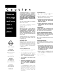
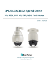
In the topology diagram shown in Figure 1, a wired corporate user and access points are connected to the Cisco
Catalyst 3850. Two wireless clients are connected to the service set identification (SSID) on the Cisco Catalyst
3850. One of the wireless users is a corporate user, and the other user is a partner. Corporate users and partner
users have different security policies defined on Cisco’s Identity Services Engine (ISE) server that is in the campus
services block. There are other servers such as call manager, video streaming server, and the Cisco Prime
™
Infrastructure server in the campus services block as well.
© 2013 Cisco and/or its affiliates. All rights reserved. This document is Cisco Public Information.
Page 3 of 70
Figure 1.
802.1X with Converged Access
The authentication, authorization, and accounting (AAA) group and RADIUS server are set up on the Cisco
Catalyst 3850. The authentication and authorization are redirected to the ISE server. The wireless clients are set
up to get authenticated using dot1x.
aaa new-model
aaa authentication dot1x CLIENT_AUTH group radius
aaa authorization network CLIENT_AUTH group radius
!
The ISE server is the RADIUS server, and the switch is defined on the ISE server as one of the network devices.
The RADIUS server needs to be defined on the switch.
radius server ise
address ipv4 9.9.9.9 auth-port 1812 acct-port 1813
timeout 60
retransmit 3
key cisco123
!
© 2013 Cisco and/or its affiliates. All rights reserved. This document is Cisco Public Information.
Page 4 of 70
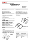
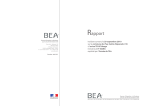
To define the Cisco Catalyst 3850, on the ISE screen, navigate to Administration Network Resources
Network Devices as in Figure 2.
Figure 2.
Device Definition in ISE
The dot1x needs to be enabled on the switch globally for wired and wireless clients.
dot1x system-auth-control
!
802.1X Configuration for Wired Users
802.1X for wired users is configured per port. Here is the port configuration:
interface GigabitEthernet1/0/13
switchport access vlan 12
switchport mode access
access-session port-control auto
access-session host-mode single-host
dot1x pae authenticator
service-policy type control subscriber DOT1X
The Cisco Catalyst 3850 also introduces session-aware networking (SaNet), which is a replacement for Auth
®
Manager that is present in current Cisco IOS Software platforms.
The objective of having SaNet is to have no dependency between features applied to sessions or authentication
method. Thus, with appropriate AAA interactions, any authentication method should derive authorization data for
any feature, to be activated on a session. This can be accomplished by using a policy model similar to Modular
Policy Framework (MPF), which is used in routing protocols, firewall rules, quality of service (QoS), and so on. For
more details, see SaNet documentation at http://www.cisco.com/en/US/docs/ios-xml/ios/san/configuration/xe3se/3850/san-overview.html. The following policy is an example for SaNet:
© 2013 Cisco and/or its affiliates. All rights reserved. This document is Cisco Public Information.
Page 5 of 70
class-map type control subscriber match-all DOT1X_NO_RESP
match method dot1x
!
policy-map type control subscriber DOT1X
event session-started match-all
1 class always do-until-failure
2 authenticate using dot1x retries 3 retry-time 60
event authentication-success match-all
event authentication-failure match-all
5 class DOT1X_NO_RESP do-until-failure
1 authentication-restart 60
!
802.1X Configuration for Wireless Users
For wireless clients, 802.1x is configured under WLAN configuration mode. The AAA authentication method is
similar to wired clients.
wlan Predator 1 Predator
security dot1x authentication-list CLIENT_AUTH
When a user provides credentials, the ISE server authenticates and authorizes the user. Upon successful
authorization, the user is assigned a specific VLAN, which provides policies based on groups or device types in
ISE. It also provides other policies such as QoS, downloadable access control list (dACL), and so on.
The client session is maintained on the Cisco Catalyst 3850 after authorization, until the session is terminated. The
client states are controlled by the wireless control manager (WCM) process.
Any end station (wired or wireless) authenticating using dot1X is termed as a “client,” and all the policies such as
dACL and QoS that are specific to this client are installed on the client entity in hardware, unlike ports in the
existing 3K switches. This is one way that consistency between wired and wireless clients is achieved.
To look at the overall wired and wireless devices connected on the switch, the following command can be used:
Switch#sh access-session
Interface
MAC Address
Gi1/0/13
Method
Domain
Status Fg Session ID
0024.7eda.6440 dot1x
DATA
Auth
0A0101010000109927B3B90C
Ca1
b065.bdbf.77a3 dot1x
DATA
Auth
0a01010150f57a300000002e
Ca1
b065.bdb0.a1ad dot1x
DATA
Auth
0a01010150f57ac20000002f
Session count = 3
Key to Session Events Status Flags:
A - Applying Policy (multi-line status for details)
D - Awaiting Deletion
F - Final Removal in progress
© 2013 Cisco and/or its affiliates. All rights reserved. This document is Cisco Public Information.
Page 6 of 70
I - Awaiting IIF ID allocation
P - Pushed Session (non-transient state)
R - Removing User Profile (multi-line status for details)
U - Applying User Profile (multi-line status for details)
X - Unknown Blocker
The following output shows the detailed view of the wireless client session:
Switch#sh access-session mac b065.bdb0.a1ad details
Interface:
IIF-ID:
MAC Address:
Capwap0
0xE49A0000000008
b065.bdb0.a1ad
IPv6 Address:
Unknown
IPv4 Address:
12.0.0.2
User-Name:
Status:
Domain:
Oper host mode:
user1
Authorized
DATA
multi-auth
Oper control dir:
both
Session timeout:
N/A
<snip….snip>
Server Policies (priority 100)
ACS ACL:
xACSACLx-IP-user1-46a243eb
Method status list:
Method
State
dot1x
Authc Success
The following is the configuration on the wired port:
Switch#sh run int gig1/0/13
Building configuration...
Current configuration : 317 bytes
!
interface GigabitEthernet1/0/13
description dot1X Wired Port in Vlan 30
switchport access vlan 30
switchport mode access
load-interval 30
access-session host-mode single-host
access-session port-control auto
dot1x pae authenticator
spanning-tree portfast
service-policy type control subscriber 802.1x
end
© 2013 Cisco and/or its affiliates. All rights reserved. This document is Cisco Public Information.
Page 7 of 70
The following is the detailed output of the wired client session:
Switch#sh access-session mac 0024.7eda.6440 details
Interface: GigabitEthernet1/0/13
IIF-ID: 0x1092DC000000107
MAC Address: 0024.7eda.6440
IPv6 Address: Unknown
IPv4 Address: 10.3.0.113
User-Name: corp1
Status: Authorized
Domain: DATA
Oper host mode: single-host
Oper control dir: both
Session timeout: N/A
Common Session ID: 0A010101000011334A316CE0
Acct Session ID: Unknown
Handle: 0x8B00039F
Current Policy: 802.1x
Server Policies:
ACS ACL:
xACSACLx-IP-Corp-506f07b4
Method status list:
Method
dot1x
State
Authc Success
Note:
In the preceding output, the ACL is installed on the client entity and not on the port.
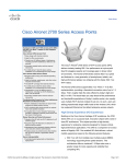
Downloadable Access Control List
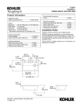
The screenshot in Figure 3 shows the dACL definition in ISE.
Figure 3.
Downloadable ACL Screen
© 2013 Cisco and/or its affiliates. All rights reserved. This document is Cisco Public Information.
Page 8 of 70
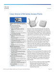
After defining ACL in ISE, it can be associated with an authorization profile, as shown in Figure 4.
Figure 4.
Note:
Authorization Profile
If a named authentication method-list is in place for AAA, an attribute needs to be set from ISE, as
shown in 4 Method-List in this example is CLIENT_AUTH.
After successful download of ACL, the client is authorized, and the following is the output of ACL:
Switch#sh access-lists
Extended IP access list xACSACLx-IP-user1-46a243eb (per-user)
1 permit udp any any eq domain
2 permit tcp any any eq domain
3 permit udp any eq bootps any
4 permit udp any any eq bootpc
5 permit udp any eq bootpc any
6 permit ip any any
Access Control List Deployment Considerations
With the Cisco Catalyst 3850 and converged access, ACLs can now be applied to wireless clients as they are
applied on wired ports/clients. The Cisco Catalyst 3850 has more ternary content-addressable memory (TCAM)
space assigned for ACLs than 3K-X switches. The following paragraphs describe some of the scalability numbers.
Table 1 summarizes the access control entries (ACEs) scalability.
Table 1.
Scale Numbers
ACL Resources
Cisco Catalyst 3850
IPv4 ACE
3000 entries
IPv6 ACE
1500 entries
L4OPs/ACL
8 L4OPs
© 2013 Cisco and/or its affiliates. All rights reserved. This document is Cisco Public Information.
Page 9 of 70
The total capacity of the ACEs is an aggregate number that constitutes all types of ACEs. One type of ACE,
however, can scale up to 1500. For example, the total number of Port ACL (PACL) access control entries cannot
exceed 1500. But a combination of PACL and Router ACL (RACL) access control entries can scale up to 3000.
Cisco Catalyst 3850 Quality of Service
One of the primary advantages of the Cisco Catalyst 3850 is the visibility into wireless packets at the access layer.
This visibility is a powerful feature and enables network administrators to apply the rich intelligent services of wired
traffic and extend these services to wireless traffic as well. QoS is one of the features that can be applied on
wireless traffic similar to that of being applied on wired network.
Significant QoS features have been introduced for wired as well as wireless on the Cisco Catalyst 3850. Some of
them are the following and are discussed in detail later in the document:
●
Modular QoS CLI (MQC)
●
Approximate Fair-Drop (AFD) algorithm for bandwidth management across wireless users, providing
hierarchical support across access points, radios, Basic Service Set Identifier (BSSID), and clients.
●
Eight queues per port (wired) and 4 queues per port (wireless)
●
Bidirectional policing support in hardware for wireless clients
●
Two-level hierarchical QoS on wired ports
●
Per-SSID bandwidth management; differentiated bandwidth management across SSIDs
Because of the inherent differences of wired and wireless media and transmission methods, there are differences
between wired and wireless QoS.
Wired QoS on the Cisco Catalyst 3850 is explained later, followed by wireless QoS in the following section.
Wired Quality of Service
Cisco Catalyst 3850 Trust Behavior
The trust behavior on the Cisco Catalyst 3850 has changed from the that of Cisco Catalyst 3K Series switches. By
default, the Cisco Catalyst 3850 trusts markings on the wired ports. For wired ports, differentiated services code
point (DSCP) markings in IP packets from endpoints such as IP phones, telepresence units, cameras, and laptops
are trusted and retained.
Retained markings are summarized in Table 2.
Table 2.
Trust Behavior
Incoming Packet
Outgoing Packet
Trust Behavior
L3
L3
Preserve DSCP/precedence
L2
L2
Not applicable
Tagged
Tagged
Preserve DSCP and class of service (CoS)
L3
Tagged
Preserve DSCP; CoS is set to 0
With the introduction of MQC, the “trust cos/dscp” CLI has been deprecated on the Cisco Catalyst 3850. However,
“trust device” on the interface level is still supported. The default mode on the interface is trusted and changes to
untrusted only when an untrusted device is detected. In the untrusted mode, the DSCP/precedence/CoS will be
reset to 0.
© 2013 Cisco and/or its affiliates. All rights reserved. This document is Cisco Public Information.
Page 10 of 70
Unlike wired, wireless is considered untrusted on the Cisco Catalyst 3850. The default trust setting for wireless
target is untrust: that is, the packets are marked down to 0 in the absence of SSID-based policy.
The startup configuration on the Cisco Catalyst 3850 always has the following CLI:
qos wireless-default-untrust
This CLI is part of the default configuration (automatically created) and cannot be modified in the current release.
That means the wireless will always be untrusted.
If trust behavior (similar to wired) is desired on wireless, table-maps need to be defined. The option of default copy
can be used to protect the markings in the table-maps.
Marking on the downstream traffic is not being preserved on wireless targets. Therefore, a table-map is required in
the downstream direction to retain the markings.
The following is a sample table-map that will retain the markings:
table-map dscp2dscp
default copy
!
Configuring Ingress Quality of Service
Ingress Classification
When creating QoS classification policies, the network administrator must consider applications that are to be
present at the access layer of the network (in the ingress direction). The applications present at the access edge
need to be classified to mark them with appropriate marking and/or policing.
MQC offers scalability and flexibility in configuring QoS and provides consistent configuration across various Cisco
switches and routers. The following sample configuration creates an extended access list for each application and
then applies it under class-map configuration mode:
ip access-list extended BULK-DATA
remark FTP
permit tcp any any eq ftp
permit tcp any any eq ftp-data
..
..
..
ip access-list extended DEFAULT
remark EXPLICIT CLASS-DEFAULT
permit ip any any
ip access-list extended MULTIMEDIA-CONFERENCING
remark RTP
permit udp any any range 16384 32767
ip access-list extended SCAVENGER
remark KAZAA
permit tcp any any eq 1214
© 2013 Cisco and/or its affiliates. All rights reserved. This document is Cisco Public Information.
Page 11 of 70
permit udp any any eq 1214
ip access-list extended SIGNALING
remark SCCP
permit tcp any any range 2000 2002
remark SIP
permit tcp any any range 5060 5061
permit udp any any range 5060 5061
ip access-list extended TRANSACTIONAL-DATA
remark HTTPS
permit tcp any any eq 443
remark ORACLE-SQL*NET
permit tcp any any eq 1521
permit udp any any eq 1521
The following is the configuration for creating a class-map for each application service and applying match
statements:
class-map match-any BULK-DATA
match access-group name BULK-DATA
class-map match-any VVLAN-SIGNALING
match ip dscp cs3
class-map match-any MULTIMEDIA-CONFERENCING
match access-group name MULTIMEDIA-CONFERENCING
class-map match-any DEFAULT
match access-group name DEFAULT
class-map match-any SCAVENGER
match access-group name SCAVENGER
class-map match-any SIGNALING
match access-group name SIGNALING
class-map match-any VVLAN-VOIP
match ip dscp ef
class-map match-any TRANSACTIONAL-DATA
match access-group name TRANSACTIONAL-DATA
Ingress Marking and Policing
It is important to limit the bandwidth that each class may use at the access layer in the ingress direction. To
achieve proper policing, accurate DSCP marking on ingress traffic at the access-layer switch is critical. It is best to
use an explicit marking command for all trusted application classes.
There are two methods for ingress marking. These are “table-map” and “set” commands. For marking down,
however, table-map is the only option that can be used.
© 2013 Cisco and/or its affiliates. All rights reserved. This document is Cisco Public Information.
Page 12 of 70
With table-maps, one can create a map of values that can be used between the same or different markings such
as DSCP, CoS, and so on. The values that can be mapped are from 0 through 99 in decimal. Table-map also has
a default mode of operation for values that do not have a mapping explicitly configured. If it is set to ignore, there
will not be any change to the marking, unless an explicit mapping is configured. It can be configured to copy or to
set a specific value.
The following is a sample table-map configuration:
table-map cos2cos
default copy
policy-map cos-trust-policy
class class-default
set cos cos table cos2cos
The following sample configuration shows how to configure policing for multiple classes on ingress ports in accesslayer switches:
policy-map Phone+PC-Policy
class VVLAN-VOIP
police 128000 8000 conform-action transmit exceed-action drop
set dscp ef
class VVLAN-SIGNALING
police 32000 8000 conform-action transmit exceed-action drop
set dscp cs3
class MULTIMEDIA-CONFERENCING
police 5000000 8000 conform-action transmit exceed-action drop
set dscp af41
class SIGNALING
police 32000 8000 conform-action transmit exceed-action drop
set dscp cs3
class TRANSACTIONAL-DATA
police 10000000 8000 conform-action transmit exceed-action set-dscp-transmit
dscp table markdown
set dscp af21
class BULK-DATA
police 10000000 8000 conform-action transmit exceed-action set-dscp-transmit
dscp table markdown
set dscp af11
class SCAVENGER
police 10000000 8000 conform-action transmit exceed-action drop
set dscp cs1
class DEFAULT
police 10000000 8000 conform-action transmit exceed-action set-dscp-transmit
dscp table markdown
© 2013 Cisco and/or its affiliates. All rights reserved. This document is Cisco Public Information.
Page 13 of 70
Applying Ingress Policies
Like other Cisco Catalyst platforms, Cisco Catalyst 3850 Switches offer two simplified methods to apply service
policies. Depending on the deployment model, either of the following methods may be used:
●
Port-based QoS: Applying service policy on a per-physical port basis will force traffic to pass through QoS
policies before entering the network.
●
VLAN-based QoS: Applying service policy on per-VLAN basis requires the policy map to be attached to a
logical Layer 3 interface or Switch Virtual Interface (SVI).
The following sample configuration shows how to deploy port-based QoS on the access-layer switches:
interface fastethernet0/4
description CONNECTED TO PHONE+PC
service-policy input Phone+PC-Policy
Egress Quality of Service
The Cisco Catalyst 3850 has eight queues per wired port. The switch can be configured to work in 2P6Q3T mode.
Voice over IP (VoIP) Expedited Forwarding (EF) and broadcast video Class Selector 5 (CS5) can be assigned to
the priority queues. Figure 5 illustrates 2P6Q3T mode.
Figure 5.
2P6Q3T Mode
class-map VOICEQ
match dscp ef
class-map match-any VIDEOQ
match dscp cs4
class-map NETWORK-MGMT
match dscp cs6
© 2013 Cisco and/or its affiliates. All rights reserved. This document is Cisco Public Information.
Page 14 of 70
class-map CALL-SIG
match dscp cs3
class-map CRITICAL-DATA
match dscp af21 af22 af23
class-map VIDEO-STREAM
match dscp af31 af32 af33
class-map Scavenger-Q
match dscp cs1
After traffic is identified using DSCP, policy bases can be applied on classifications.
policy-map 2P6Q3T
class VOICEQ
priority level 1
class VIDEOQ
priority level 2
class NETWORK-MGMT
bandwidth remaining percent 10
class CALL-SIG
bandwidth remaining percent 10
class CRITICAL-DATA
bandwidth remaining percent 10
class VIDEO-STREAM
bandwidth remaining percent 10
class SCAVENGER
bandwidth remaining percent 1
class class-default
bandwidth remaining percent 25
The egress policy can be applied to the port or L3 interface similar to the ingress policy.
Wireless Quality of Service
Wireless Targets
In wireless QoS, there are two terms: upstream and downstream. Upstream means ingressing from the access
point and egressing from the wired network. Downstream means ingressing from the wired network and egressing
out to the access point. The following table summarizes the QoS marking/policing and queuing capabilities on each
type of target interface: access point, radio, SSID, and client.
In wireless targets, QoS policies can be applied on multiple levels. Each of these targets is discussed in the
following sections.
© 2013 Cisco and/or its affiliates. All rights reserved. This document is Cisco Public Information.
Page 15 of 70
Wireless: Ingress Quality of Service
Ingress Marking and Policing on Wireless Client
In the ingress direction, traffic can be marked and policed at client level. The following example provides
differentiated marking and policing for the different class of application sourced from the client:
policy-map PER-CLIENT
class VOICE
set dscp ef
police 128k 8000 exceed-action drop
class SIGNALING
set dscp cs3
police 32k 8000 exceed-action drop
class MULTIMEDIA-CONFERENCING
set dscp af41
police 5m 8000 exceed-action drop
class TRANSACTIONAL
set dscp af21
class CLASS-DEFAULT
set dscp default
The client policy can be applied directly under the SSID interface (as in the following), or it can be pushed from the
policy server (ISE).
wlan open 1 Employees
service-policy client input PER-CLIENT
© 2013 Cisco and/or its affiliates. All rights reserved. This document is Cisco Public Information.
Page 16 of 70
The applied policy can be shown with the following CLI:
Switch# sh policy-map interface wireless client
Client 000A.CC10.0001
Service-policy input: Standard-Employee
Class-map: Voice (match-all)
Match: access-group name Voice
police:
cir 128000 bps, bc 4000 bytes
conformed 0 bytes; actions:
transmit
…
QoS Set
dscp ef
…
Class-map: TRANSACTIONAL-DATA (match-all)
Match: access-group name TRANSACTIONAL-DATA
QoS Set
dscp af21
Class-map: class-default (match-any)
Match: any
QoS Set
dscp default
The preceding configuration enforces the policer per wireless client that joined on the SSID. In this case the Cisco
Catalyst 3850 uses microflow policers that act per client.
© 2013 Cisco and/or its affiliates. All rights reserved. This document is Cisco Public Information.
Page 17 of 70
If the policy name is downloaded from the ISE server, the server needs to be configured as shown in Figure 6, with
the AV pair ip:sub-qos-policy-in=Standard-Employee.
Figure 6.
Authentication Profile
The same policy can be applied for open wired ports as well. The policy needs to be attached to the port and not to
the clients. Currently QoS policies cannot be attached to wired “clients.”
Note:
Wired port application is described earlier in the wired section.
Ingress Policies on WLAN/SSID
Although the policy application happens at the WLAN level from a CLI standpoint, the policies are actually applied
to every instance of the SSID in each of the <access point, radio> pairs in the system. This is internally referred to
as the BSSID. SSID is used synonymously with BSSID in this document. At SSID level we can police and mark.
However, at SSID level, marking is only possible with a table-map. In the following example only table-map with a
default action of copy is defined. It retains the incoming DSCP in the IP packet.
© 2013 Cisco and/or its affiliates. All rights reserved. This document is Cisco Public Information.
Page 18 of 70
table-map dscp2dscp
default copy
Policy-map TRUST
Table Map dscp2dscp
default copy
The QoS policy is applied under the WLAN configuration. The SSID policy is applied as shown in the following
example. This results in “trusted” behavior for traffic ingressing from wireless, similar to wired.
wlan open 1 Employees
service-policy input TRUST
Wireless: Egress Quality of Service
This explains the capabilities of QoS that are available on the Cisco Catalyst 3850. On the egress (downstream),
QoS capabilities exist per access point, radio, SSID, and client.
Policy on Access Point/Port
The ports that are connected to access points are termed wireless ports throughout this document. There are four
queues on the wireless ports to match the four queues on the access point. The queue structure is 2P2Q3T: two
priority queues, and two SRR queues, with three thresholds each. The recommended queuing configuration in a
2P2Q3T structure is shown in Figure 7.
Figure 7.
2P2Q3T Queue Model for Queuing Application Traffic
Four queues are created at the port level when a port is configured as a wireless port: real time 1 (RT1), RT2,
unicast non real time (NRT), and multicast nonclient NRT.
The multicast nonclient is classified as any traffic that has a destination IP address of multicast or broadcast.
© 2013 Cisco and/or its affiliates. All rights reserved. This document is Cisco Public Information.
Page 19 of 70
The following is the default behavior of the four queues:
Q0 (RT1): Control traffic
Q1 (RT2): None
Q2 (NRT): Everything other than multicast NRT and control traffic
Q3 (multicast NRT): Multicast and nonclient traffic
Default QoS policy is applied to the wireless port in the downstream (egress) direction. On port level no policy is
supported in upstream (ingress) direction. The policy on the port is applied to the CAPWAP encapsulated packets
egressing out to the access point.
The default wireless port policy includes a port shaper and a child policy. The parent policy cannot be modified by
user and is controlled by the WCM. This parent policy has a port shaper that is the sum of the radio rates on the
access point. The child policy on the wireless port is user configurable.
The following describes default child policy configuration:
policy-map port_child_policy
class non-client-nrt-class
bandwidth remaining ratio 10
The following is the overall wireless port policy:
Switch#sh policy-map in gig1/0/3
GigabitEthernet1/0/3
Service-policy output: defportangn
Class-map: class-default (match-any)
Match: any
Queueing
(total drops) 0
(bytes output) 17633136
shape (average) cir 600000000, bc 2400000, be 2400000
target shape rate 600000000
Service-policy : port_child_policy
Class-map: non-client-nrt-class (match-any)
Match: non-client-nrt
Queueing
(total drops) 0
(bytes output) 17633136
© 2013 Cisco and/or its affiliates. All rights reserved. This document is Cisco Public Information.
Page 20 of 70
bandwidth remaining ratio 10
Class-map: class-default (match-any)
Match: any
(total drops) 0
(bytes output) 0
The “port_child_policy” can be modified by the user to queue different application traffic at the SSID level. This
traffic is queued toward the appropriate queues at the port level. The following is the “port_child_policy”
configuration example:
Switch#sh run policy-map port_child_policy
Building configuration...
Current configuration : 227 bytes
!
class non-client-nrt-class
bandwidth remaining ratio 10
class voice
priority level 1
police 20000
class video
priority level 2
police 20000
class class-default
bandwidth remaining ratio 25
The “police 20000” statement in the “class voice” and “class video” polices aggregates multicast traffic for each
class at the port/access point level. It does not police unicast traffic that is classified using the “voice” and “video”
class-maps.
Policy on Radio
Radio-level policy is not user configurable. This is a rate limiter that limits all traffic going to the radio. Currently only
two radios are supported per access point, and hence two rate limiters supported per access point. The Cisco
Catalyst 3850 polls the access point to discover the maximum rate of the radio, and a shaper is placed in order to
limit the oversubscription of the radio. Based on the discovery of maximum rate, the rate limiter can limit at 200 or
400 Mbps for 2.4G and 5G bands, respectively.
The following is the policy at radio level:
Switch#sh policy-map interface wireless radio
Radio dot11b iifid: 0x104F10000000011.0xC9CA4000000004
Service-policy output: def-11gn
Class-map: class-default (match-any)
© 2013 Cisco and/or its affiliates. All rights reserved. This document is Cisco Public Information.
Page 21 of 70
Match: any
shape (average) cir 200000000, bc 800000, be 800000
target shape rate 200000000
Radio dot11a iifid: 0x104F10000000011.0xCF8F4000000005
Service-policy output: def-11an
Class-map: class-default (match-any)
Match: any
shape (average) cir 400000000, bc 1600000, be 1600000
target shape rate 400000000
Although the preceding policy shows its shaping, it does not buffer or smooth out the rate. Essentially this is a rate
limiter at radio level.
Policy on Service Set Identification
Policy at SSID level or at BSSID level is user configurable in both upstream and downstream directions. SSID-level
policies are applied in the WLAN configuration mode.
In downstream direction, the recommended policy is a hierarchical queuing policy with table-map-based marking in
the parent class default. In absence of a table-map configuration in the SSID, the packets are all remarked down to
0. The packets are sent through the NRT queue at the port level. This is because the WLAN is considered to be
untrusted in the absence of a table-map.
If voice/video traffic needs to be prioritized, the child policy-maps on both the port/access point and SSID should be
configured with class-maps and appropriate actions. If the child policy for voice/video differentiation is missing on
either one of the targets (port/access point and/or SSID), the voice and video traffic will not be prioritized on the
wireless network.
The following is an example of two SSIDs: enterprise and guest. The voice/video traffic is prioritized on the
enterprise, while the guest traffic is classified as default and given the appropriate queuing treatment.
Policy-map enterprise-ssid-child
Class
voice
Priority level 1
Police
20000
Class video
Priority level 2
Police
20000
Policy-map enterprise-ssid
Class class-default
bandwidth remaining percent 70
set wlan-user-priority dscp dscp2up1
set dscp dscp dscp2dscp1
service-policy enterprise-ssid-child
© 2013 Cisco and/or its affiliates. All rights reserved. This document is Cisco Public Information.
Page 22 of 70
Policy-map guest-ssid
Class class-default
Shape average percent 20
On the enterprise SSID class-map voice and video, the policer enforces the aggregate unicast traffic at the BSSID
level. The class default is configured to provide a minimum bandwidth allocation to the enterprise SSID, which is
able to utilize the additional unused bandwidth in the absence of congestion.
The class default on the guest SSID, however, is shaped to 20 percent of the available bandwidth irrespective of
the bandwidth utilization and congestion.
Client
Client policies can be applied in both upstream and downstream directions. Client policies are user configurable
and can be applied under the WLAN configuration mode. When applied in WLAN configuration mode, all clients
under SSID receive the same policy, but the policy enforcement is done on a per-user basis using microflow
policing.
The client-level policy can also be applied from the AAA server. The policy is defined locally on the switch, and the
name of the policy is downloaded from the AAA server at the time of client authorization. With the help of
downloadable policies, any differentiated policy can be applied for clients or client groups.
After the client policy is associated with a client, the client policy can be looked up using the client MAC address.
The following is the output of a client policy-map applied in the egress (downstream) direction:
Switch#sh policy-map interface wireless client mac b065.bdbf.77a3
Client B065.BDBF.77A3 iifid:
0x1047D4000000011.0xD7E4C000000076.0xDD94000000028D.0xFCEBC000000373
Service-policy output: egress-client
Class-map: class-default (match-any)
Match: any
police:
cir 500000 bps, bc 15625 bytes
conformed 404432 bytes; actions:
transmit
exceeded 0 bytes; actions:
drop
conformed 0000 bps, exceed 0000 bps
Flexible NetFlow
Flexible NetFlow (FnF) is an integral part of Cisco IOS Software that collects and measures data, allowing all
routers or switches in the network to become a source of telemetry and a monitoring device. FnF allows extremely
granular and accurate traffic measurements and high-level aggregated traffic collection. FnF provides real-time
network monitoring, security incident detection, and classification of flow of network traffic.
© 2013 Cisco and/or its affiliates. All rights reserved. This document is Cisco Public Information.
Page 23 of 70
Cisco Catalyst 3850 NetFlow Architecture (Wired and Wireless)
NetFlow Cisco Catalyst 3850 Overview
The Cisco Catalyst 3850 supports both ingress and egress FnF on all ports of the switch at line rate. Switch raw
scalability is up to 24K cached flows, whereas it is 8K for ingress and 16K for egress per UADP ASIC. The Cisco
Catalyst 3850 supports NetFlow Version 9, with IPv4, IPv6, Layer 2 flows, and sampled NetFlow. TCP flags are
also exported as part of the flow information. When Cisco Catalyst 3850 switches are stacked together, each
individual stack member exports its own flows to the collector. The Cisco Catalyst 3850 supports up to 16 flow
monitors with eight different collectors simultaneously per flow monitor. Microflow policing is supported only for
wireless clients.
The FnF feature on the Cisco Catalyst 3850 is enabled on the IP base version and earlier. The Cisco Catalyst 3850
48-port switch has two UADP ASICs per switch, and the Cisco Catalyst 3850 24-port switch has one UADP ASIC.
NetFlow Configuration on Cisco Catalyst 3850 Switch
There are three components of FnF configuration: flow record, flow exporter, and flow monitor.
Flow Record
The NetFlow flow record is made up of primary fields and nonprimary fields. Primary fields are the fields from
packet headers that are used for classifying and characterizing the flow. Additional information can be added to the
flow record, and this information is contained in nonprimary fields. Match commands as seen in the following are
used to define primary fields, while collect commands are used to define the nonprimary fields.
Configuring a Flow Record (Ingress)
flow record v4
match ipv4 tos
match ipv4 protocol
match ipv4 source address
match ipv4 destination address
match transport source-port
match transport destination-port
match interface input
collect interface output
collect transport tcp flags
collect counter bytes long
collect counter packets long
collect timestamp absolute first
collect timestamp absolute last
collect counter bytes layer2 long
Note:
“match interface output” cannot be configured in the ingress flow monitor. In order to get the egress
interface information, use the “collect interface output” command in an ingress flow record.
Similarly, “match interface input” is not supported on an egress flow record; use “collect interface input” as shown
in the following:
© 2013 Cisco and/or its affiliates. All rights reserved. This document is Cisco Public Information.
Page 24 of 70
Configuring a Flow Record (Egress)
flow record v4out
match ipv4 protocol
match ipv4 tos
match ipv4 source address
match ipv4 destination address
match transport source-port
match transport destination-port
match interface output
collect interface input
collect transport tcp flags
collect counter bytes long
collect counter packets long
collect timestamp absolute first
collect timestamp absolute last
collect counter bytes layer2 long
Exporter/Collector Information
There are two primary methods to access NetFlow data: using a CLI with show commands or using an application
that receives exported NetFlow information sent periodically by the switch.
flow exporter Collector
destination 10.1.1.28
dscp 48
transport udp 2055
template data timeout 30
option exporter-stats timeout 30
Flow exporter commands specify the destination IP address of the exporter/collector. DSCP specifies the DSCP
value for datagrams sent to the exporter/collector. The next command specifies the L4 port on which the
exporter/collector application listens for the NetFlow export packets from the switch. Template commands enable
the switch to send the NetFlow template after specified number of seconds to the exporter/collector. The Cisco
Catalyst 3850 supports up to eight different exporters/collectors simultaneously per flow monitor.
Flow Monitor
Flow monitors are the FnF component that is applied to interfaces. Flow monitors consist of a record, cache
parameters, and the exporter/collector. The flow monitor cache is automatically created at the time the flow monitor
is configured on the first interface.
Flow monitor is the container for the following information:
●
Flow record
●
Flow cache parameters
●
Exporter/collector information
© 2013 Cisco and/or its affiliates. All rights reserved. This document is Cisco Public Information.
Page 25 of 70
flow monitor v4
exporter Collector
exporter Collector 1
cache timeout active 60
cache timeout inactive 20
record v4
Attaching a Flow Monitor to Supported Port Types
Wired Port
interface GigabitEthernet1/0/1
description Interface for WIRED CLIENT in CONVERGED VLAN
switchport access vlan 10
switchport mode access
ip flow monitor v4 input
ip flow monitor v4out output
load-interval 30
no shutdown
!
Wireless WLAN Port
wlan SSID 1 SSID
client vlan 12
ip flow monitor v4 input
ip flow monitor v4out output
no shutdown
!
VLAN Interface
Vlan configuration 500
ip flow monitor v4 input
ip flow monitor v4out output
!
Configure Simple Network Management Protocol for Exporter
snmp-server community public RO
snmp-server community private RO
Simple Network Management Protocol (SNMP) configurations enable the external collectors to read the
configuration related to NetFlow on the switch and collect flows.
© 2013 Cisco and/or its affiliates. All rights reserved. This document is Cisco Public Information.
Page 26 of 70
Flexible NetFlow Outputs
To display the status and statistics for a flexible NetFlow flow monitor, use the
“Show Flow monitor” command in privileged EXEC mode.
Switch# show flow monitor
Flow Monitor v4:
Description:
User defined
Flow Record:
v4
Flow Exporter:
Collector
Cache:
Type:
normal (Platform cache)
Status:
allocated
Size:
Unknown
Inactive Timeout:
15 secs
Active Timeout:
60 secs
Update Timeout:
1800 secs
To display the flexible NetFlow configuration status for an interface, use the “Show Flow Interface” commands in
privileged EXEC mode.
Switch# show flow interface
Interface GigabitEthernet2/0/26
FNF:
FNF:
monitor:
v4
direction:
Input
traffic(ip):
on
monitor:
v4out
direction:
Output
traffic(ip):
on
To display aggregated flow statistics from a flow monitor cache, use the “Show flow monitor cache format table”
command.
Switch# Show flow monitor v4 cache format table
Cache type:
Normal (Platform cache)
Cache size:
Unknown
Current entries:
2
Flows added:
26492
Flows aged:
26490
- Active timeout
(
1800 secs)
4
- Inactive timeout
(
15 secs)
26486
IPV4-SRC-ADDR DST-ADDR SRC-PORT DST-PORT INTF-INPUT intf-output bytes-long pktslong time-abs-first time-abs-last
=============== ===============
====================
10.1.22.102 10.1.1.22
52226
=============
5060
=============
Gi1/0/4 LIIN0
© 2013 Cisco and/or its affiliates. All rights reserved. This document is Cisco Public Information.
1038
3
19:52:12.755
Page 27 of 70
19:52:12.755
10.1.22.101 10.1.1.22
19:52:10.755
51524
5060
Gi1/0/3 LIIN0
1038
3
19:52:10.755
To display top N destination aggregated flow statistics from a flow monitor cache, use the following command.
Switch# show flow monitor v4 cache aggregate ipv4 destination add sort counter
bytes long top 4
Processed 4 flow
Aggregated to 4 flow
Showing the top 4 flow
IPV4 DST ADDR
flows
bytes long
pkts long
==========
====================
====================
===============
10.1.1.22
1
1038
3
10.1.1.92
2
1038
3
10.1.1.82
4
1038
3
10.1.1.52
9
1038
3
To display top N source address aggregated flow statistics from a flow monitor cache, use the following command.
Switch# sh flow monitor v4 cache aggregate ipv4 source address sort highest ipv4
source address top 2
Processed 2 flows
Aggregated to 2 flows
Showing the top 2 flows
IPV4 SRC ADDR
===============
flows
bytes long
pkts long
==========
====================
====================
10.1.22.102
1
1038
3
10.1.22.101
1
1038
3
To display the status and statistics for IPv6 flexible NetFlow flow monitor, use the “Show Flow monitor” command
in privileged EXEC mode.
Switch# show flow moni v6_m1 cache format table
Cache type:
Normal (Platform cache)
Cache size:
Unknown
Current entries:
12
Flows added:
30
Flows aged:
- Inactive timeout
18
(
15 secs)
© 2013 Cisco and/or its affiliates. All rights reserved. This document is Cisco Public Information.
18
Page 28 of 70
IPV6 SRC ADDR
long
IPV6 DST ADDR
TRNS
SRC PORT
=============================================
TRNS DST PROT
bytes long pkts
==================
2322::2
FF02::1:FF00:1
0
34560
58
72
1
2322::2
2201::2
1024 1026
17
9166290
43649
2322::2
2201::2
1024 1027
17
9166290
43649
2322::2
2201::2
1024 1024
17
9166500
43650
To display top N IPv6 destination address aggregated flow statistics from a flow monitor cache, use the following
command:
Switch# show flow monitor v6_m1 cache aggregate ipv6 destination address sort
counter bytes long top 2
Processed 10 flows
Aggregated to 2 flows
Showing the top 2 flows
IPV6 DESTINATION ADDRESS:
2322::2
counter flows:
5
counter bytes long:
3278889600
counter packets long:
15613760
IPV6 DESTINATION ADDRESS:
2201::2
counter flows:
5
counter bytes long:
3221137920
counter packets long:
15338752
To display top N source address aggregated flow statistics from a flow monitor cache, use the following command:
Switch# show flow monitor v6_m1 cache aggregate ipv6 source address sort highest
ipv6 source address top 2
Showing the top 2 flows
IPV6 SOURCE ADDRESS:
2322::2
counter flows:
5
counter bytes long:
3919704180
counter packets long:
18665258
IPV6 SOURCE ADDRESS:
2201::2
counter flows:
5
counter bytes long:
3913954800
counter packets long:
18637880
© 2013 Cisco and/or its affiliates. All rights reserved. This document is Cisco Public Information.
Page 29 of 70
Multicast Overview (Traditional and Converged Multicast)
Efficient and intelligent use of bandwidth is paramount, particularly with the advent of video, mobility, and cloud
technologies. It is also critical considering the surge in related one-to-many or many-to-many communicationbased applications. Multicast helps to fulfill the requirement of such bandwidth-intensive applications with its
inherent ability to replicate a single stream when and where necessary.
In today’s network, replication for wired clients is performed at the network switches. There are two methods that
multicast works in wireless. Either the controller replicates to the access points that have interested clients, or the
controller replicates one packet to the multicast group address to which all access points are joined, offloading the
replication to the multicast-enabled network infrastructure. Hence there is a duplication of one multicast source
stream: one for wired, one for wireless.
With the Cisco Catalyst 3850 and the wired/wireless convergence, there is only one multicast source stream in the
network. The Cisco Catalyst 3850 replicates this stream to both wired and wireless clients. This helps in reducing
the number of streams from the same source, thus conserving bandwidth and enhancing overall network
performance.
The wired multicast configuration is the same as that of existing Cisco Catalyst 3K Series switches. Refer to the IP
Multicast Configuration Guide for configuring IP multicast on the wired network.
Restrictions of IP Multicast Routing Configuration
The following are the restrictions for configuring IP multicast routing:
●
IP multicast routing is not supported on switches running the LAN Base feature set.
●
Multicast Flexlink is not supported on the switch.
●
Layer 3 IPv6 multicast routing is not supported on the switch.
Configuring Wireless IP Multicast on Cisco Catalyst 3850
There are two modes in which wireless multicast works on the Cisco Catalyst 3850. In the basic mode, the switch
replicates individual packets to only those ports where the access point has interested clients. In this mode, the
replication of packets occurs before the CAPWAP encapsulation is added to the packet, destined to each
interested access point. This increases the recirculation on the switch since each packet to each access point is
passed through the recirculation block. However, this leads to efficient use of bandwidth in the switch since the
replicated packets are only sent to those access points that have interested clients.
In multicast-multicast mode, the switch and all the access points connected to it join one unique multicast group
that is not used anywhere else in the network. The ingress source stream from the campus network is replicated
once and encapsulated in CAPWAP with the destination address of this multicast group (formed between the
switch and all access points). In this mode, the replication happens only once for the group - hence only one
recirculation for CAPWAP encapsulation - and this packet is transmitted to all the connected access points. In this
mode, number of packets being switched by the UADP ASIC is optimized over the cost of switch bandwidth. The
switch always uses the management interface IP address as the source for sending these CAPWAP-encapsulated
multicast packets. The access point decapsulates the outer CAPWAP header and sends the original multicast
packets as broadcast at the lowest data rate on all BSSID and radio.
© 2013 Cisco and/or its affiliates. All rights reserved. This document is Cisco Public Information.
Page 30 of 70
The videostream mode is a further enhancement of the preceding. Instead of sending the multicast as broadcast at
the lowest data rate, the access point converts the original multicast packet as unicast and sends it only to the
interested client at the highest available data rate. This works the same way as it works in today’s Cisco Unified
Wireless Network as the function is performed at the access point level.
The following commands enable wireless multicast on the Cisco Catalyst 3850 Switch:
Switch#conf t
Switch(config)#ip multicast-routing
Switch(config)#wireless multicast
Switch(config)#wireless broadcast
Switch(config)#Wireless multicast non-ip
Switch(config)#interface interface-id
Switch(config-if)# ip pim {dense-mode | Sparse-Mode | Sparse-dense-mode}
Switch(config)#vlan configuration <id>
Switch(config-vlan)#ipv6 nd suppress
Switch(config-vlan)#ipv6 snooping
Switch(config-vlan)#end
Switch#copy running-config startup-config
Irrespective of multicast routing being enabled, Internet Group Management Protocol (IGMP) snooping must be
enabled on the client VLAN for wireless clients to receive IP multicast traffic.
To enable multicast routing on a Cisco Catalyst 3850 Switch, the “ip multicast-routing” command is used. To send
multicast on wireless to all clients (interested in multicast or not), the “wireless-multicast” command is used.
“Wireless-broadcast” command enables broadcasting of packets on wireless data plane of switch.
To enable multicast flooding on wireless, the “wireless multicast non-ip” command can be used.
Multicast Mode Configuration
Wireless multicast packets are required to be sent to the access point as CAPWAP encapped packet in a unicast
tunnel or a multicast tunnel. When multicast mode is enabled, WCM creates a multicast CAPWAP tunnel in Cisco
IOS Software and converts the access point tunnels to multicast mode pointing to the multicast tunnel.
When an access point is in multicast mode, the multicast/broadcast packets to the client behind this access point
are sent to this access point in an outer multicast tunnel.
All the access points in the multicast mode must watch for the multicast group, which is specified while creating the
multicast tunnel. Following is a multicast mode configuration:
Switch# conf t
Switch(config)# ap capwap multicast <Multicast IP Address>
© 2013 Cisco and/or its affiliates. All rights reserved. This document is Cisco Public Information.
Page 31 of 70
Following is the basic configuration of wireless multicast:
●
Configure IGMP snooping and querier:
Switch(config)#ip igmp snooping
Switch(config)#ip igmp snooping querier
●
Configure wireless multicast and access point CAPWAP mode:
Switch(config)#wireless multicast
Switch(config)#ap capwap multicast 234.5.6.7
●
Configure multicast routing (3850 only):
Switch(config)#ip multicast-routing
Switch(config)#interface vlan 100
Switch(config)# ip pim sparse-dense-mode
Multicast Show Commands
You can display information to learn resource usage and solve network problems. You can also display information
about node reachability and discover the routing path that packets of your device are taking through the network.
You can use any of the privileged EXEC commands in the following table to display various routing statistics.
To display wireless multicast status on switch and access point multicast mode and each VLAN’s broadcast and
non-IP multicast status, use the “Show Wireless Multicast” command in privileged EXEC mode.
Switch#show wireless multicast
show wireless multicast
Multicast
: Enabled
AP Capwap Multicast
: Unicast
Wireless Broadcast
: Disabled
Wireless Multicast non-ip-mcast
: Disabled
Vlan
Non-ip-mcast
Broadcast
MGID
-----------------------------------------------------1
Enabled
Enabled
Disabled
410
Enabled
Enabled
Disabled
411
Enabled
Enabled
Enabled
412
Disabled
Disabled
Enabled
413
Disabled
Disabled
Enabled
414
Enabled
Enabled
Disabled
© 2013 Cisco and/or its affiliates. All rights reserved. This document is Cisco Public Information.
Page 32 of 70
To display all (S,V,G) list and the corresponding MGID value, use the “Show wireless multicast group summary”
command in privileged EXEC mode.
Switch#show wireless multicast group summary
IPv4 groups
------------MGID
Source
Group
Vlan
----------------------------------------------------------4160
0.0.0.0
239.255.67.250
412
4162
0.0.0.0
239.255.255.250
412
4163
0.0.0.0
224.0.1.60
412
Switch#show ip igmp snooping wireless mgid
Total number of L2-MGIDs
= 3
Total number of MCAST MGIDs = 3
Wireless multicast is Enabled in the system
Vlan
bcast
nonip-mcast
mcast
mgid
Stdby Flags
1
Disabled
Disabled
Enabled
Disabled
0:0:1:0
410
Disabled
Disabled
Enabled
Disabled
0:0:1:0
411
Disabled
Disabled
Enabled
Enabled
0:0:1:0
412
Disabled
Disabled
Enabled
Enabled
0:0:1:0
413
Disabled
Disabled
Enabled
Enabled
0:0:1:0
Index
MGID
(S, G, V)
-------------------------------------------------------160 4163
(0.0.0.0, 224.0.1.60, 412)
409 4162
(0.0.0.0, 239.255.255.250, 412)
409 4160
(0.0.0.0, 239.255.67.250, 412)
To display IP IGMP snooping tracking by VLAN on a switch with SVG to client mapping, use the “Show ip igmp
snooping igmpv2-tracking” command in privileged EXEC mode.
Switch#show ip igmp snooping igmpv2-tracking
Client to SGV mappings
---------------------Client: 10.33.170.4 Port: Ca1
Group: 239.255.255.250 Vlan: 412 Source: 0.0.0.0 blacklisted: no
Client: 10.33.170.33 Port: Ca7
Group: 239.255.255.250 Vlan: 412 Source: 0.0.0.0 blacklisted: no
Client: 10.33.170.75 Port: Ca1
Group: 239.255.255.250 Vlan: 412 Source: 0.0.0.0 blacklisted: no
© 2013 Cisco and/or its affiliates. All rights reserved. This document is Cisco Public Information.
Page 33 of 70
Group: 239.255.67.250 Vlan: 412 Source: 0.0.0.0 blacklisted: no
SGV to Client mappings
---------------------Group: 224.0.1.60 Source: 0.0.0.0 Vlan: 412
Client: 10.33.170.101 Port: Ca10 Blacklisted: no
Group: 239.255.67.250 Source: 0.0.0.0 Vlan: 412
Client: 10.33.170.75 Port: Ca1 Blacklisted: no
Group: 239.255.255.250 Source: 0.0.0.0 Vlan: 412
Client: 10.33.170.75 Port: Ca1 Blacklisted: no
Client: 10.155.156.71 Port: Ca1 Blacklisted: no
To display the detailed information on a particular multicast group with client association, use the “show wireless
multicast group vlan” command in privileged EXEC mode.
Switch#show wireless multicast group 239.255.255.250 vlan 412
Source : 0.0.0.0
Group
: 239.255.255.250
Vlan
: 412
MGID
: 4162
Number of Active Clients : 4
Client List
------------Client MAC
Client IP
Status
--------------------------------------------------------------2477.0336.e574
10.33.170.4
MC_ONLY
2477.035e.d848
10.33.170.109
MC_ONLY
6033.4b24.fa89
10.33.170.33
MC_ONLY
7cd1.c391.c674
10.33.170.75
MC_ONLY
To display the IP IGMP snooping groups on a switch, use the “show ip igmp snooping groups” command in
privileged EXEC mode.
Switch#show ip igmp snooping groups
Vlan
Group
Type
Version
Port List
---------------------------------------------------------------------412
224.0.1.60
igmp
v2
Ca10
412
239.255.67.250
igmp
v3
Ca1
412
239.255.255.250
igmp
v2,v3
Ca1, Ca7
© 2013 Cisco and/or its affiliates. All rights reserved. This document is Cisco Public Information.
Page 34 of 70
To display the multicast groups that are directly connected to the switch and that were learned through IGMP, use
the “show ip igmp groups” command in privileged EXEC mode.
Switch#show ip igmp groups
IGMP Connected Group Membership
Group Address
Interface
Uptime
Expires
Last Reporter
239.255.255.255
Vlan413
4d18h
00:02:42
10.32.104.1
239.255.255.255
Vlan412
4d18h
00:01:39
10.33.170.1
239.255.255.250
Vlan412
01:27:18
00:02:45
10.33.170.75
To display the reachability to the multicast group with ICMP echo request, use the “Ping” command in privileged
EXEC mode.
Switch#ping 239.255.255.255
Type escape sequence to abort.
Sending 1, 100-byte ICMP Echos to 239.255.255.255, timeout is 2 seconds:
Reply to request 0 from 10.32.104.1, 20 ms
Reply to request 0 from 10.33.170.1, 20 ms
Reply to request 0 from 10.32.104.1, 20 ms
To display multicast-related information of an interface, use the “Show ip igmp interface vlan” command in
privileged EXEC mode.
Switch#show ip igmp interface vlan412
Vlan412 is up, line protocol is up
Internet address is 10.33.170.1/24
IGMP is enabled on interface
Current IGMP host version is 3
Current IGMP router version is 3
IGMP query interval is 60 seconds
IGMP configured query interval is 60 seconds
IGMP querier timeout is 120 seconds
IGMP configured querier timeout is 120 seconds
IGMP max query response time is 10 seconds
Last member query count is 2
Last member query response interval is 1000 ms
Inbound IGMP access group is not set
IGMP activity: 43 joins, 38 leaves
Multicast routing is enabled on interface
Multicast TTL threshold is 0
Multicast designated router (DR) is 10.33.170.1 (this system)
IGMP querying router is 10.33.170.1 (this system)
Multicast groups joined by this system (number of users):
224.2.127.254(1)
239.255.255.255(1)
© 2013 Cisco and/or its affiliates. All rights reserved. This document is Cisco Public Information.
Page 35 of 70
To display the IP IGMP membership status of all multicast groups on a switch, use the “show ip igmp membership
all” command in privileged EXEC mode.
Switch#show ip igmp membership all
Flags: A
L
- aggregate, T - tracked
- Local, S - static, V - virtual, R - Reported through v3
I - v3lite, U - Urd, M - SSM (S,G) channel
1,2,3 - The version of IGMP, the group is in
Channel/Group-Flags:
/ - Filtering entry (Exclude mode (S,G), Include mode (G))
Reporter:
<mac-or-ip-address> - last reporter if group is not explicitly tracked
<n>/<m>
- <n> reporter in include mode, <m> reporter in exclude
Channel/Group
Reporter
Uptime
Exp.
*,239.255.255.255
10.32.104.1
4d18h
02:05 3LA
Flags
Vl413
Interface
*,239.255.255.255
10.33.170.1
4d18h
02:59 3LA
Vl412
*,239.255.255.250
10.33.170.33
01:32:53 02:59 2A
Vl412
To display the statistics of a particular multicast group, use the “show ip igmp membership” in privileged EXEC
mode.
Switch#show ip igmp membership 239.255.255.255
Flags: A
L
- aggregate, T - tracked
- Local, S - static, V - virtual, R - Reported through v3
I - v3lite, U - Urd, M - SSM (S,G) channel
1,2,3 - The version of IGMP, the group is in
Channel/Group-Flags:
/ - Filtering entry (Exclude mode (S,G), Include mode (G))
Reporter:
<mac-or-ip-address> - last reporter if group is not explicitly tracked
<n>/<m>
- <n> reporter in include mode, <m> reporter in exclude
Channel/Group
Reporter
Uptime
Exp.
*,239.255.255.255
10.32.104.1
4d18h
00:39 3LA
Vl413
*,239.255.255.255
10.33.170.1
4d18h
01:34 3LA
Vl412
© 2013 Cisco and/or its affiliates. All rights reserved. This document is Cisco Public Information.
Flags
Interface
Page 36 of 70
Converged Access with the Cisco Catalyst 3850
The Cisco Catalyst 3850 Switch offers scalable, resilient, and future-proofed wired and wireless services. It serves
as an integrated wireless LAN controller for up to 50 Cisco access points and 2000 clients per stack. The Cisco
Catalyst 3850 can form the basis of a deployment in which the access points and clients can scale up to 250 Cisco
access points and 16,000 clients, respectively. The converged access deployment mode builds on an existing
Cisco Unified Wireless Network. For deployments scaling beyond 250 access points and 16k clients, the Cisco
Catalyst 3850 can be used with the Cisco 5760 Wireless LAN Controller and can scale up to 72k access points and
864k clients.
The converged access deployment is achieved by distributing some of the functions from the wireless LAN
controllers (WLCs) down to the Cisco Catalyst 3850 Switches in the access. The access switches terminate the
CAPWAP encapsulated wireless traffic locally, converting the wireless traffic into Ethernet frames. This includes
the added advantage of unifying wired and wireless traffic on the switch and makes it possible to apply the rich and
intelligent wired services on wireless traffic.
This section explains the converged access deployment with the Cisco Catalyst 3850 Switches.
Before the details are explored, it is important to understand the functions that are distributed down to the access
switches.
Distributed Functions Enabling Converged Access
There are two important software functions among others that enable wireless services on WLC.
Mobility Agent
This software function manages CAPWAP tunnel terminations from access points and builds a database of client
stations (endpoints) that are served locally as well as roamed from an anchor WLC. The mobility agent also serves
the function of 802.1x authenticator, proxy IGMP, and proxy ARP for locally served clients.
Mobility Controller
This complements software functions of the mobility agent and manages mobility (roaming) for client stations from
one WLC to another, and provides guest access functionality by building a CAPWAP tunnel with the guest anchor
controller in the DMZ. The mobility controller manages the access point licenses as well. It also provides a central
way of managing the RF spectrum residing outbound of the access points. This is called radio resource
management (RRM) and includes rogue detection, dynamic channel assignment, transmit power on the access
®
points, coverage hole detection, and CleanAir . In addition, the mobility controller builds a database of client
stations across all the mobility agents. The mobility controller is also responsible for caching the pairwise master
key (PMK) of all clients on all the mobility agents, enabling fast roaming of the clients within its subdomain and
mobility group.
Because of the preceding important functions, a mobility controller is a mandatory element in the converged
access deployment. The mobility controller software function runs in the active member of a Cisco Catalyst 3850
Switch stack and can be failed over to the standby member in the stack in the event of an active failover. A switch
stack hosting the mobility controller function can also run the mobility agent function on the active member for all
the locally connected Cisco access points.
© 2013 Cisco and/or its affiliates. All rights reserved. This document is Cisco Public Information.
Page 37 of 70
The mobility controller’s area of responsibility lies in the mobility subdomain it controls. All the mobility agents in the
subdomain form CAPWAP mobility tunnels to the mobility controller and report local and roamed client states to the
mobility controller. The mobility controller builds a database of client stations across all the mobility agents.
By distributing these functions in the Cisco Catalyst 3850 Switches in the access, converged access provides
scalable, resilient, feature-rich wireless services in conjunction with wired services and features.
Mobility Oracle
This is a software function that is responsible for client station visibility across the mobility controllers (mobility
subdomains) in its mobility domain. The mobility oracle is an optional entity in the hierarchy of mobility agentmobility controller-mobility oracle. The advantage of configuring a mobility oracle for a converged access
deployment is that it scales and reduces control events that occur for initial client joins and client roams, especially
in a multi-mobility controller environment. This function cannot be hosted on the Cisco Catalyst 3850, and can only
be hosted on software-upgraded Cisco 5508 WLC, WiSM2, or Cisco 5760 WLC. Typically the mobility oracle is
hosted on a controller appliance running the mobility controller function.
Logical Hierarchical Groupings of Roles
Mobility Group
Today’s Cisco Unified Wireless Network defines mobility group as a logical group of mobility controllers to enable
fast roaming of clients within the mobility controllers of a mobility group.
Switch Peer Group (SPG)
The converged access deployment defines a switch peer group (SPG) as a logical group of mobility agents within
one mobility controller (or mobility subdomain). The main advantage of configuring SPGs is to constrain the
roaming traffic to switches that form the SPG. When the mobility agents are configured in one SPG on the mobility
controller, the software automatically forms full mesh CAPWAP tunnels between the mobility agent switches These
CAPWAP tunnels can be formed in a multilayer network design (where the mobility agent switches are L2 adjacent
on a VLAN spanned across) or a routed access design (where the mobility agent switches are L3 adjacent). (See
Figure 8.)
© 2013 Cisco and/or its affiliates. All rights reserved. This document is Cisco Public Information.
Page 38 of 70
Figure 8.
Hierarchical Roles in Converged Access
The SPGs are designed as a group of mobility agent switches to where the users frequently roam. It is important
that roams within an SPG are local to the SPG and need not involve the mobility controller, whereas roams across
an SPG require traffic to traverse the mobility controller.
Converged Access Network Design with Cisco Catalyst 3850
If the wireless deployment consists of one Cisco Catalyst 3850 Switch operating as mobility controller as well as
mobility agent, which might be suited for a small branch type deployment, 50 Cisco access points and 2000 clients
are supported, as seen in Figure 9.
© 2013 Cisco and/or its affiliates. All rights reserved. This document is Cisco Public Information.
Page 39 of 70
Figure 9.
Single Cisco Catalyst 3850 Stack for Wired/Wireless in Small Branch
If the wireless deployment consists of only a Cisco Catalyst 3850 Switch running as a mobility controller with
several other switches operating as mobility agents, 16 mobility agents can be grouped together in one SPG under
one mobility controller. The access point and client scale remain at 50 Cisco access points and 2000 clients, as
seen in Figure 10. Only the Cisco 5508, 5760 controller appliances, or the WiSM2 service module supports the
guest access controller functionality in the DMZ. The guest access controller functionality is not supported on the
Cisco Catalyst 3850.
Figure 10.
Single Mobility Controller with Cisco Catalyst 3850 Switches for Wired/Wireless in Medium/Large Branch
© 2013 Cisco and/or its affiliates. All rights reserved. This document is Cisco Public Information.
Page 40 of 70
For medium campus wireless deployments scaling up to 250 Cisco access points and 16,000 clients, 7 mobility
controller switches (with other mobility agent switches operating as mobility agents in their SPG) can be grouped
together in a mobility group with guest access provided by guest anchor controller in the DMZ, as seen in
Figure 11. If there is no guest access operational, 8 mobility controller switches can be grouped together in a
mobility group.
Figure 11.
Multiple Mobility Controllers with Cisco Catalyst 3850 Switches for Wired/Wireless in Medium/Large Campus
For typical large campus wireless deployments scaling beyond 250 Cisco access points and 16,000 clients, the
converged access allows the option of operating the Cisco Catalyst 3850 Switches as mobility agents, peering with
a software upgraded Cisco 5508 or WiSM2 Wireless LAN Controller, or a Cisco 5760 WLC operating as mobility
controller, as seen in Figure 12.
© 2013 Cisco and/or its affiliates. All rights reserved. This document is Cisco Public Information.
Page 41 of 70
Figure 12.
5508/WiSM2/5760 Controller Appliances with Cisco Catalyst 3850 Switches for Large Campus
Configuring Converged Access with Cisco Catalyst 3850
This section explains how to configure the wireless services on the Cisco Catalyst 3850. Consider a large branch
or a small campus that has a deployment scale of up to 250 access points and 16,000 clients that can be
implemented only using Cisco Catalyst 3850 Switches. The converged access deployment will be explained using
a case study starting from a small branch in the initial phase growing to a large branch/medium campus
deployment. (See Figure 13.)
Figure 13.
Configuring Mobility Controller on Cisco Catalyst 3850
© 2013 Cisco and/or its affiliates. All rights reserved. This document is Cisco Public Information.
Page 42 of 70
The Cisco access points must be connected directly to the Cisco Catalyst 3850 Switch. One Cisco Catalyst 3850
Switch forms the access layer. The distribution in this example is made of the Cisco Catalyst 4500E Supervisor 7-E
systems in virtual switching system (VSS) configuration. It is a multilayer network design in which the L3 SVI for L2
VLANs on the access is defined on the VSS system. The Cisco Catalyst 3850 connects to the VSS through a L2
port channel configured as an 802.1Q trunk carrying all the VLANs. Three VLANs are used: Vlan 501 for wired
clients, Vlan 500 for wireless clients, and Vlan 601 for switch/wireless management. The access points must be
configured in the wireless VLAN for them to be controlled by the Cisco Catalyst 3850, in this case Vlan 601.
The configuration to enable wireless termination on the Cisco Catalyst 3850 Switch is as shown in the following:
ap cdp
ap country US
wireless management interface Vlan601
wireless mobility controller
The “ap cdp” enables CDP process on the Cisco access points connected to the Cisco Catalyst 3850 Switch. “ap
country US” defines the country code for that access point The wireless management interface command is used
to source the access point CAPWAP and other CAPWAP mobility tunnels. The next command enables the switch
to act as the mobility controller role for the converged access deployment. This previous command requires a
reboot of the switch. Save the configuration and reload the switch.
The Cisco Catalyst 3850 downloads the software to the access point when it joins the switch for the very first time.
This process takes a longer time since the access point needs to download the code and reboot in order to join the
switch. Again, this happens the very first time the access point connects to the switch; all subsequent reloads
include the access point booting with this code and joining the switch.
The next step is to configure SSIDs, define wireless LAN (WLAN) on the switch, with corresponding VLAN used for
wireless clients, the authentication and ciphers method, and the AAA server profile to use for this WLAN. In the
following example, the name of the SSID is Predator, using the client VLAN 500 we defined for wireless clients,
and enabling WPA, WPA2 with TKIP, using 802.1X authentication with the AAA server defined elsewhere in the
configuration.
For an open SSID, configure “no security wpa” following the WLAN configuration. For preshared key (PSK)
security, configure under WLAN configuration.
wlan Predator 1 Predator
aaa-override
client association limit 2000
client vlan 500
security wpa wpa2 ciphers tkip
security dot1x authentication-list ise
no shutdown
no security wpa akm dot1x
security wpa akm psk set-key ascii 0 skunkworks
© 2013 Cisco and/or its affiliates. All rights reserved. This document is Cisco Public Information.
Page 43 of 70
Relevant excerpts from outputs regarding wireless configuration on the Cisco Catalyst 3850 are shown in the
following:
MC1#show wireless mobility summary
Mobility Controller Summary:
Mobility Role
: Mobility Controller
Mobility Protocol Port
: 16666
Mobility Group Name
: default
Controllers configured in the Mobility Domain:
IP
Public IP
Group Name
Multicast IP
Link Status
----------------------------------------------------------------------------20.1.3.2
-
default
-
UP
: UP
MC1#show wlan summary
Number of WLANs: 1
WLAN Profile Name
SSID
VLAN
Status
---------------------------------------------------------------------------1
Predator
Predator
500
UP
MC1#show capwap summary
CAPWAP Tunnels General Statistics:
Number of Capwap Data Tunnels
= 2
Number of Capwap Mobility Tunnels
= 0
Number of Capwap Multicast Tunnels
= 0
Name
APName
Type PhyPortIf Mode
McastIf
------ -------------------------------- ---- --------- --------- ------Ca5
3502E_G2/0/25_83A9
data Gi2/0/25
unicast
-
Ca4
3602I_G2/0/1_3A04
data Gi2/0/1
unicast
-
Name
SrcIP
SrcPort DestIP
DstPort DtlsEn MTU
------ --------------- ------- --------------- ------- ------ ----Ca5
20.1.3.2
5247
20.1.3.54
63548
No
1657
Ca4
20.1.3.2
5247
20.1.3.53
58274
No
1657
The preceding output shows that two data CAPWAP tunnels are formed with the Cisco access points, 3502E off of
GigabitEthernet 2/0/25 (second switch in the stack) and 3602I off of GigabitEthernet 2/0/1. 20.1.3.2 is the
switch/wireless management IP address of this switch. The last section in the output of "show capwap summary"
displays the source IP address with which the switch forms the data CAPWAP tunnels with the access points with
their IP addresses listed, as 20.1.3.54 on destination port 63584 and 20.1.3.53 on destination port 58274.
Consider the one-switch stack network experiences growth, and now the network administrator needs to add more
Cisco Catalyst 3850 Switches and expand wireless coverage to more endpoints and devices. (See Figure 14.)
© 2013 Cisco and/or its affiliates. All rights reserved. This document is Cisco Public Information.
Page 44 of 70
Figure 14.
Configuring Mobility Agents and Switch Peer Group on Cisco Catalyst 3850
In this case the additional Cisco Catalyst 3850 Switches can be added and configured as mobility agents with the
previously configured switch acting as mobility controller. The mobility agents can be configured in one SPG.
Relevant configurations to be done on the mobility controller are given in the following:
wireless mobility controller peer-group SPG1
wireless mobility controller peer-group SPG1 member ip 20.1.5.2 public-ip
20.1.5.2
wireless mobility controller peer-group SPG1 member ip 20.1.7.2 public-ip
20.1.7.2
where an SPG, SPG1, is defined on the mobility controller, with 20.1.5.2 and 20.1.7.2 as the switch/wireless
management IP addresses of the mobility agent switches configured as members of SPG1.
On the mobility agent switches, one needs to configure the mobility controller, SSID, WLAN, and authentication
methods. The following is the configuration shown on the MA1 switch as seen in the preceding network diagram.
© 2013 Cisco and/or its affiliates. All rights reserved. This document is Cisco Public Information.
Page 45 of 70
wireless mobility controller ip 20.1.3.2 public-ip 20.1.3.2
wireless management interface Vlan602
wlan Predator 1 Predator
aaa-override
client association limit 2000
client vlan 500
security wpa wpa2 ciphers tkip
security dot1x authentication-list ise
no shutdown
ap cdp
where 20.1.3.2 is the switch/wireless management IP address of the mobility controller switch, Vlan 602 is the
switch/wireless management interface, and Vlan 500 is the client VLAN that is spanned across from the mobility
controller switch.
Relevant similar configuration is done on the other member of the SPG1 on the MA2 switch, as seen in the
following:
wireless mobility controller ip 20.1.3.2 public-ip 20.1.3.2
wireless management interface Vlan603
wlan Predator 1 Predator
client vlan 500
security wpa wpa2 ciphers tkip
security dot1x authentication-list ise
no shutdown
ap cdp
where 20.1.3.2 is the switch/wireless management IP address of the mobility controller switch, VLAN 603 is the
wireless management interface, and VLAN 500 is the client VLAN that is spanned across from the mobility
controller switch.
Notice that the SPG definitions and the SPG membership are configured only on the mobility controller switch.
Only the mobility controller definition is configured on the actual mobility agent switches.
The SPG membership defined on the mobility controller is irrespective of the connectivity between the mobility
controller and mobility agent switches. The access network might be Layer 2 connected to the distribution and/or
operating in routed access design to the distribution. (See Figure 15.)
© 2013 Cisco and/or its affiliates. All rights reserved. This document is Cisco Public Information.
Page 46 of 70
Figure 15.
Configuring Mobility Group on Multiple Mobility Controllers on Cisco Catalyst 3850
Assume that there was an acquisition of the company next door, and now the two networks have to be integrated
in the current network. The network in the acquired company operates in routed access design mode, as shown by
the diagram. The new switch can be configured to operate as a mobility agent under the previously defined mobility
controller switch in the network.
As far as the SPG membership is concerned, there is a choice. If the two user groups are going to be integrated,
OR in terms of keeping the roams simple, the customer can configure just one SPG under a Cisco Catalyst 3850based mobility controller. One SPG defined on a Cisco Catalyst 3850 mobility controller switch can contain up to
16 member mobility agents in the SPG.
The other choice is to create a different SPG on the mobility controller switch and insert the new mobility agent
switches in this new SPG. If the user groups from the present company and the acquired company are not going to
roam across the respective workspaces, then a new SPG can be created in such a case. In the example network
preceding, the administrator chooses to create a second SPG, an assumption convenient in order to better explain
the roaming effect on clients.
Relevant configuration that needs to be done on the mobility controller in this case is as in the following:
wireless mobility controller peer-group SPG2
wireless mobility controller peer-group SPG2 member ip 20.1.8.2 public-ip
20.1.8.2
where an SPG, SPG2, is defined on the mobility controller, with 20.1.8.2 as the switch/wireless management IP
addresses of the mobility agent switch configured as member of SPG2.
© 2013 Cisco and/or its affiliates. All rights reserved. This document is Cisco Public Information.
Page 47 of 70
Relevant configurations done on the MA3 switch in this case are given in the following:
wireless mobility controller ip 20.1.3.2 public-ip 20.1.3.2
wireless management interface Vlan604
wlan Predator 1 Predator
aaa-override
client vlan 701
security wpa wpa2 ciphers tkip
security dot1x authentication-list ise
no shutdown
ap cdp
where 20.1.3.2 is the switch/wireless management IP address of the mobility controller switch, VLAN 604 is the
wireless management interface, and VLAN 701 is the client VLAN on the mobility agent switch operating in routed
access mode.
Now assume that business is good and the company experiences growth more than ever. What started as a small
branch has evolved to be a larger branch with a deployment need of scaling to more than 50 access points. With
just one mobility controller switch in the branch, the deployment is limited to 50 access points. The network
administrator can configure another Cisco Catalyst 3850 Switch to operate as an mobility controller to support a
similar deployment of 50 access points. (See Figure 16.)
Figure 16.
Multiple Mobility Controller Configuration on Cisco Catalyst 3850
© 2013 Cisco and/or its affiliates. All rights reserved. This document is Cisco Public Information.
Page 48 of 70
These two mobility controller switches can be grouped together in one mobility group to enable fast roaming
between clients of each respective subdomain.
Relevant configuration that needs to be done on the existing mobility controller switch is as given in the following:
wireless mobility group member ip 20.1.9.2 public-ip 20.1.9.2 group MG
wireless mobility group name MG
where MG is the mobility group name that is created, and 20.1.9.2 is the switch/wireless management IP address
of the new mobility controller added in the mobility group.
Configuration that needs to be done on the new mobility controller switch that was brought online is given in the
following:
wireless mobility controller
wireless mobility group member ip 20.1.3.2 public-ip 20.1.3.2 group MG
wireless mobility group name MG
wireless management interface Vlan605
wlan Predator 1 Predator
aaa-override
client vlan 702
security wpa wpa2 ciphers tkip
security dot1x authentication-list ise
no shutdown
ap cdp
where 20.1.3.2 is the switch/wireless management IP address of the existing mobility controller switch, MG is the
name of the mobility group that was created, VLAN605 is the wireless management interface on this mobility
controller switch, SSID named Predator is created, VLAN702 is the client VLAN for wireless endpoints on this
switch, authentication and encryption parameters are defined for this WLAN, and CDP is being enabled on all the
access points connecting to this switch.
This is a scalable method of deploying converged access with Cisco Catalyst 3850 Switches since each switch has
the capability to do 40 Gbps of wireless traffic termination. The preceding network can collectively terminate up to
320 Gbps of wireless traffic: 8 switches (4 in stack, and 4 acting as standalone). This sufficiently demonstrates the
capability of the Cisco Catalyst 3850 Switch to be future proofed for 802.11ac when that standard comes around.
Roaming in Cisco Unified Wireless Network
Before roaming is explained in this section, it is essential to understand some terminologies that are used while
explaining roams in converged access deployment, starting with point of presence (PoP) and point of attachment
(PoA).
Point of presence (PoP) is defined as the point in the network where the wired infrastructure first sees the wireless
traffic. Packet conversions from 802.11 (wireless) to 802.3 (Ethernet) and vice versa take place at this point. PoP
serves several functionalities. It serves as a point for symmetrical routing and also serves where network security
policy is applied to the wireless traffic. In the Cisco Unified Wireless Network, the controller is where the PoP is
defined, since wireless traffic is terminated and converted to Ethernet frames at the controller, and it is at this point
that the wired infrastructure sees the frames from wireless endpoints.
© 2013 Cisco and/or its affiliates. All rights reserved. This document is Cisco Public Information.
Page 49 of 70
Point of attachment (PoA) moves with user mobility and is defined as the access point to which the user joins or
roams.
There are two types of roams within the wireless network: intracontroller roams and intercontroller roams:
●
Intracontroller roams occur when a user roams from one access point to another access point connected
to the same controller.
●
Intercontroller roams occur when a user roams from an access point connected to one controller to
another access point connected to a different controller.
There are two types of roams that can occur within intercontroller roams: L2 roams and L3 roams:
●
L2 roam occurs when the user roams from an access point connected to its controller to a different access
point connected to another controller, where the two controllers are L2 adjacent to each other. This is
typically the case in most deployments where the WLCs are centrally deployed in either the data center or a
campus services block, with the client VLANs spanned between the controllers. In the Cisco Unified
Wireless Network, in an L2 roam, both the PoP and the PoA move to the controller where the user has
roamed. The previous controller transfers the entire client context (MAC address, IP address, ACL policy,
QoS policy, IGMP group membership, and so on) to the new controller to which the client roamed.
(See Figure 17.)
Figure 17.
L2 Roam in Cisco Unified Wireless Network
© 2013 Cisco and/or its affiliates. All rights reserved. This document is Cisco Public Information.
Page 50 of 70
The previous controller does not hold any state of the client that has roamed to another controller. In this
case the client traffic is CAPWAP encapsulated by the access point and terminated at the new controller
with which access point has associated.
●
L3 roam occurs when the user roams from an access point connected to its controller to a different access
point connected to another controller, where the two controllers are L3 adjacent to each other.
(See Figure 18.)
Figure 18.
L3 Roam in Cisco Unified Wireless Network
This is the case when individual controllers are deployed at each distribution block in the campus network, where
the client VLANs are not spanned across. In an existing Cisco Unified Wireless Network, only the PoA moves with
the user mobility, and PoP remains with the initial controller the client first joined. In this case the PoP is also called
the anchor controller, and the PoA is called the foreign controller. The anchor and the foreign controllers hold the
client state since even though the client physically moves to another controller, its traffic is still back-hauled at the
anchor for symmetric routing and policy application.
© 2013 Cisco and/or its affiliates. All rights reserved. This document is Cisco Public Information.
Page 51 of 70
Understanding Roams in Converged Access
Since roams in Cisco Unified Wireless Network are explained earlier, this section explains the roams as they occur
in converged access mode. It will be clear that the roams in converged access deployment are no different than
those that occur in an existing Cisco Unified Wireless Network. In converged access deployment, QoS policies are
applied at the foreign or PoA switch, and ACL policies are applied at the anchor or PoP switch.
In converged access mode, there are two methods of supporting roams: tunneled (sticky) mode and nontunneled
(nonsticky) mode.
Tunneled mode is the default method of supporting L2 roams and the only method of supporting L3 roams in
converged access deployment. This means that even for L2 roams, by default, only the PoA moves with the user
mobility, and PoP is maintained at the anchor switch for stateful policy application.
Figure 19 shows the switches are trunked to the distribution VSS, and the client wireless VLAN 500 is spanned
across the access switches. The initial client join occurs on the MA1 switch. The initial client traffic profile is
CAPWAP encapsulated to the switch. The switch terminates the wireless traffic and sends out a converted
Ethernet frame. Hence PoP and PoA both are on MA1 for the initial client join. After clients roam to MA2, the PoP
stays at MA1, and the PoA moves to MA2, as seen earlier. Hence, the roamed traffic is CAPWAP encapsulated to
the new mobility agent. The new mobility agent encapsulates this traffic on the full mesh SPG1 tunnel to PoP
switch. After arriving on the PoP switch, the traffic is terminated and converted and shipped off into the wired world
by MA1. Since the client roams within the SPG, the roamed traffic does not need to traverse the mobility controller
switch. Typically the SPG will be formed around switches within a distribution block inside a building, or a floor:
areas to which most users roam.
Figure 19.
L2 Roam in Tunneled Mode in Converged Access
© 2013 Cisco and/or its affiliates. All rights reserved. This document is Cisco Public Information.
Page 52 of 70
There is a provision per WLAN that the administrator can configure, if they want a L2 roam like the Cisco Unified
Wireless Network, where both the PoP and PoA of the user moves. This is the nontunneled (nonsticky) L2 roam.
The advantage of this roam is that the roamed traffic does not need to be back-hauled to the PoP switch, since the
PoP moves along with the user mobility. The roamed traffic is terminated locally at the new mobility agent and
delivered to the wired world, decreasing latency for application traffic. This type of roam, though decreasing
application latency, might increase client roam times.
As Figure 20 shows, initial client join is on MA1. This wireless traffic is terminated locally and switched to the wired
world. When the clients roam to an access point connected to MA2, both PoP and PoA move to the new mobility
agent switch. No client state is retained by MA1, where the clients initially joined.
This roam is exactly like the existing Cisco Unified Wireless Network L2 roam.
Figure 20.
L2 Roam in Nontunneled Mode in Converged Access
The L3 roams are supported by the tunneled (sticky) method, as explained earlier.
© 2013 Cisco and/or its affiliates. All rights reserved. This document is Cisco Public Information.
Page 53 of 70
Traffic Paths in Converged Access
This section explains the traffic path (profile) for local and roamed wireless clients across the different SPGs and
mobility controllers. (See Figure 21.)
Figure 21.
Client Roams Within an SPG in Converged Access
As seen earlier, roams within an SPG are constrained within the anchor and foreign switches of the SPG.
As mentioned before, traffic for wireless clients that roam across an SPG has to traverse a mobility controller.
Assume that the mobility controller does the routing for the traffic that is roamed across an SPG. In Figure 21, the
client roams from initial MA1 in SPG1 to MA3 in SPG2. In this case the roamed traffic is terminated and
encapsulated at the new mobility agent, in the mobility agent-to-mobility controller CAPWAP tunnel and switched to
MC1. The mobility controller knows the anchor (PoP) switch for this client and encapsulates the traffic and switches
it to the anchor, MA1. The anchor switch applies ACLs to this traffic and also serves symmetrical routing in case
the roam is an L3 roam. (See Figure 22.)
© 2013 Cisco and/or its affiliates. All rights reserved. This document is Cisco Public Information.
Page 54 of 70
Figure 22.
Client Roams Across Mobility Controller in Converged Access
In the preceding scenario, an intersubdomain (intermobility controller) roam is explained. The initial client join
happens at MA1 in SPG1. The wireless traffic is terminated locally at MA1 and delivered to the wired side when the
client is static. When the client roams to an access point connected to MC2, it roams from the subdomain whose
master is MC1. In this case, the traffic path for the roamed client is terminated at the foreign (PoA) MC2 switch.
The foreign (PoA) MC2 switch encapsulates this traffic in the mobility controller-to-mobility controller CAPWAP
tunnel and switches the traffic to MC1. This switch encapsulates this traffic in the mobility controller-to-mobility
agent CAPWAP tunnel and lands it back to the anchor (PoP) MA1 switch. The ACL policy is applied at the anchor
switch (MA1), and this switch forwards this traffic into the wired portion of the network.
Relevant Outputs for Tracking Client Roams in Converged Access
This section explains how all the preceding theory does look in practice. This section will cover relevant outputs for
wireless clients as they initially join the wireless network and follow them as they roam through the wireless
network.
The client wireless VLAN is spanned across three switches (MC1, MA1, and MA2). The fourth mobility agent
switch, MA3, is in a routed access design across which the client wireless VLAN cannot be spanned.
The second mobility controller switch, MC2, is also a routed access design across which the client wireless VLAN
cannot be spanned.
The L2 roam by default in converged access is tunneled. The example network covers the scenarios in which L2
tunneled roam, followed by L3 roam, and lastly L2 nontunneled roams occur.
© 2013 Cisco and/or its affiliates. All rights reserved. This document is Cisco Public Information.
Page 55 of 70
Table 3 is a list of switch names, IP addresses, their roles in SPG, and mobility group that form part of the example
network. Understanding this will help explain the client roams as they roam from one switch to another.
Table 3.
Switch Roles and Other Details in Example Topology
Switch Name
IP Address
Mobility Role
Switch Peer Group
Mobility Group
MC1
20.1.3.2
Mobility controller
-
MG
MA1
20.1.5.2
Mobility agent
SPG1
MG
MA2
20.1.7.2
Mobility agent
SPG1
MG
MA3
20.1.8.2
Mobility agent
SPG2
MG
MC2
20.1.9.2
Mobility controller
-
MG
Figure 23 shows initial client join on MA1
Figure 23.
Initial Client Join on MA1
MA1#show wireless client summary
Number of Local Clients : 2
MAC Address
AP Name
WLAN State
Protocol
-------------------------------------------------------------------------------b065.bdb0.a1ad 3602I_G1/0/1_66BC
1
UP
11n(5)
b065.bdbf.77a3 3602I_G1/0/1_66BC
1
UP
11n(5)
© 2013 Cisco and/or its affiliates. All rights reserved. This document is Cisco Public Information.
Page 56 of 70
Initial client join on MA1, as seen in CLI on the switch, where it shows the client MAC address, to which access
point it is connected, and the WLAN and 11n on 5GHz:
MA1#show wcdb database all
Total Number of Wireless Clients = 2
Clients Waiting to Join
= 0
Local Clients
= 2
Anchor Clients
= 0
Foreign Clients
= 0
MTE Clients
= 0
Mac Address
VlanId IP Address
Src If
Auth
Mob
-------------- ------ --------------- ------------------ -------- ------b065.bdbf.77a3
500 20.1.1.53
0x00DC7DC000000005 RUN
LOCAL
b065.bdb0.a1ad
500 20.1.1.52
0x00DC7DC000000005 RUN
LOCAL
MA1#show wireless client mac b065.bdbf.77a3 detail
Client MAC Address : b065.bdbf.77a3
Client Username : blackbird
AP MAC Address : 203a.076f.abe0
AP Name: 3602I_G1/0/1_66BC
Client State : Associated
Wireless LAN Id : 1
Wireless LAN Name: Predator
Protocol : 802.11n - 5 GHz
Channel : 157
IPv4 Address : 20.1.1.53
Mobility State : Local
EAP Type : PEAP
Interface : WIRELESS_VLAN
VLAN : 500
Access VLAN : 500
MA1#show mac address dynamic | include Ca1
Vlan
MAC Address
Type
-----
-----------
-------
-----
Ports
500
b065.bdb0.a1ad
DYNAMIC
Ca1
500
b065.bdbf.77a3
DYNAMIC
Ca1
where “Ca1” is the access point CAPWAP data tunnel and it shows that the client MAC addresses are seen behind
the Ca1 interface.
As mentioned earlier that the mobility controller has visibility of all clients across all mobility agents, the following is
the client visibility CLI on the mobility controller for clients local on the mobility agent.
© 2013 Cisco and/or its affiliates. All rights reserved. This document is Cisco Public Information.
Page 57 of 70
MC1#sh wireless mobility controller client summary
Number of Clients : 2
State is the Sub-Domain state of the client.
* indicates IP of the associated Sub-domain
Associated Time in hours:minutes:seconds
MAC Address
State
Anchor IP
Associated IP
Associated Time
------------------------------------------------------------------------------b065.bdb0.a1ad
Local
0.0.0.0
20.1.5.2
00:00:23
b065.bdbf.77a3
Local
0.0.0.0
20.1.5.2
00:00:35
Notice the anchor IP 0.0.0.0 indicating that these clients are locally connected on the mobility agent switch whose
IP address is 20.1.5.2 (MA1).
Consider when the clients roam from mobility agent to mobility controller switch (Figure 24).
Figure 24.
Client Roams Within an SPG in Converged Access
© 2013 Cisco and/or its affiliates. All rights reserved. This document is Cisco Public Information.
Page 58 of 70
The following are the relevant outputs displaying the client roam. In this case, MA1 becomes the anchor switch,
while MC1 becomes the foreign switch.
MC1#show wireless client summary
Number of Local Clients : 2
MAC Address
AP Name
WLAN State
Protocol
-------------------------------------------------------------------------------b065.bdb0.a1ad 3602I_G2/0/1_3A04
1
UP
11n(5)
b065.bdbf.77a3 3602I_G2/0/1_3A04
1
UP
11n(5)
MC1#show wcdb database all
Total Number of Wireless Clients = 2
Foreign Clients
= 2
MTE Clients
= 0
Mac Address
VlanId IP Address
Src If
Auth
Mob
-------------- ------ --------------- ------------------ -------- ------b065.bdbf.77a3
500 20.1.1.53
0x00E685C000000006 RUN
FOREIGN
b065.bdb0.a1ad
500 20.1.1.52
0x00E685C000000006 RUN
FOREIGN
MC1#show wireless client mac b065.bdbf.77a3 detail
Client MAC Address : b065.bdbf.77a3
Client Username : blackbird
AP MAC Address : 8875.5687.b830
AP Name: 3602I_G2/0/1_3A04
Wireless LAN Name: Predator
Protocol : 802.11n - 5 GHz
IPv4 Address : 20.1.1.53
Mobility State : Foreign
Mobility Anchor IP Address : 20.1.5.2
Mobility Move Count : 1
Interface : WIRELESS_VLAN
VLAN : 500
Notice that the mobility state is “foreign” in the client database on the switch to which client roams. Also notice that
the client detail on the roamed-to switch shows local access point name, mobility state, and the mobility anchor IP
address (20.1.5.2). 20.1.5.2 is the switch/wireless management switch of the switch the client initially joined, MA1.
Relevant outputs on the anchor switch (MA1 in this case) are as in the following:
MA1#show wireless client summary
Number of Local Clients : 2
MAC Address
AP Name
WLAN State
Protocol
-------------------------------------------------------------------------------b065.bdb0.a1ad 20.1.3.2
1
UP
Mobile
b065.bdbf.77a3 20.1.3.2
1
UP
Mobile
© 2013 Cisco and/or its affiliates. All rights reserved. This document is Cisco Public Information.
Page 59 of 70
Comparing the preceding output with the one in the initial client join, notice that the access point name changes to
the switch IP address to where the clients roamed (switch/wireless management IP address of MC1 in this case),
and the protocol state becomes “Mobile.”
MA1#sh wcdb data all
Total Number of Wireless Clients = 2
Clients Waiting to Join
= 0
Local Clients
= 0
Anchor Clients
= 2
Foreign Clients
= 0
MTE Clients
= 0
Mac Address
VlanId IP Address
Src If
Auth
Mob
-------------- ------ --------------- ------------------ -------- ------b065.bdbf.77a3
500 20.1.1.53
0x00D03BC000000002 RUN
ANCHOR
b065.bdb0.a1ad
500 20.1.1.52
0x00D03BC000000002 RUN
ANCHOR
Relevant outputs displaying the client detail on the anchor switch, MA1, as in the following:
MA1#sh wireless client mac b065.bdbf.77a3 detail
Client MAC Address : b065.bdbf.77a3
Client Username : blackbird
AP MAC Address : 0000.0000.0000
AP Name: 20.1.3.2
Client State : Associated
Wireless LAN Id : 1
Wireless LAN Name: Predator
Protocol : Mobile
Channel :
IPv4 Address : 20.1.1.53
Mobility State : Anchor
Mobility Foreign IP Address : 20.1.3.2
Interface : WIRELESS_VLAN
VLAN : 500
Access VLAN : 500
© 2013 Cisco and/or its affiliates. All rights reserved. This document is Cisco Public Information.
Page 60 of 70
where the mobility state is “anchor,” and the access point name is the switch/wireless management IP address of
the foreign switch (MC1): 20.1.3.2. (See Figure 25.)
Figure 25.
Client Roams Across SPG in Converged Access
In the preceding scenario the endpoints roam from the mobility controller to another mobility agent in SPG2. The
thing to note here is that this is an L3 roam, since the client wireless VLAN 500 is not spanned across to this
mobility agent. The client retains the IP address it received at initial client join at MA1. Its traffic is back-hauled from
the new mobility agent (MA3), to its mobility controller (MC1), to the anchor mobility agent switch (MA1), where it is
forwarded into the wired portion of the network as an Ethernet frame.
Starting off with the relevant outputs on the switch to which the clients roamed:
MA3#show wireless client summary
Number of Local Clients : 2
MAC Address
AP Name
WLAN State
Protocol
-------------------------------------------------------------------------------b065.bdb0.a1ad 3602I_G1/0/1_3A2A
1
UP
11n(5)
b065.bdbf.77a3 3602I_G1/0/1_3A2A
1
UP
11n(5)
MA3#show wcdb database all
Total Number of Wireless Clients = 2
Foreign Clients
= 2
MTE Clients
= 0
© 2013 Cisco and/or its affiliates. All rights reserved. This document is Cisco Public Information.
Page 61 of 70
Mac Address
VlanId IP Address
Src If
Auth
Mob
-------------- ------ --------------- ------------------ -------- ------b065.bdbf.77a3
701 20.1.1.53
0x00C9D9C000000004 RUN
FOREIGN
b065.bdb0.a1ad
701 20.1.1.52
0x00C9D9C000000004 RUN
FOREIGN
Since the roam is across an SPG, the mobility controller gets involved in the mobility in this case. Relevant outputs
from the mobility controller for the client visibility are displayed in the following:
MC1#show wcdb database all
Total Number of Wireless Clients = 2
MTE Clients
Mac Address
= 2
VlanId IP Address
Src If
Auth
Mob
-------------- ------ --------------- ------------------ -------- ------b065.bdbf.77a3
0 0.0.0.0
0x00CB4E4000000004 RUN
MTE
b065.bdb0.a1ad
0 0.0.0.0
0x00CB4E4000000004 RUN
MTE
MC1#
MC1#show wireless mobility controller summary
Number of Clients : 2
State is the Sub-Domain state of the client.
* indicates IP of the associated Sub-domain
Associated Time in hours:minutes:seconds
MAC Address
State
Anchor IP
Associated IP
Associated Time
-------------------------------------------------------------------------------b065.bdb0.a1ad
Local
20.1.5.2
20.1.8.2
00:01:24
b065.bdbf.77a3
Local
20.1.5.2
20.1.8.2
00:01:29
The preceding output displays a new option: MTE. It is defined as mobility tunnel endpoint and points to the fact
that the mobility controller has to switch the packets for these clients ingressing over the mobility agent-to-mobility
controller tunnel from foreign, and egressing out the mobility agent-to-mobility controller tunnel to anchor.
Relevant outputs at the anchor switch are the following:
MA1#show wireless client summary
Number of Local Clients : 2
MAC Address
AP Name
WLAN State
Protocol
-------------------------------------------------------------------------------b065.bdb0.a1ad 20.1.8.2
1
UP
Mobile
b065.bdbf.77a3 20.1.8.2
1
UP
Mobile
MA1#
MA1#show wcdb database all
Total Number of Wireless Clients = 2
Anchor Clients
= 2
© 2013 Cisco and/or its affiliates. All rights reserved. This document is Cisco Public Information.
Page 62 of 70
Mac Address
VlanId IP Address
Src If
Auth
Mob
-------------- ------ --------------- ------------------ -------- ------b065.bdbf.77a3
500 20.1.1.53
0x00D03BC000000002 RUN
ANCHOR
b065.bdb0.a1ad
500 20.1.1.52
0x00D03BC000000002 RUN
ANCHOR
Figure 26 shows client roam across MCs
Figure 26.
Client Roams Across Mobility Controllers (Intersubdomain) in Converged Access
In the preceding scenario, the wireless clients roam from the mobility agent in SPG2 across the subdomain to an
access point connected to another mobility controller (MC2) in the same mobility group.
This roam again has to be back-hauled using the mobility controllers through the mobility controller-to-mobility
controller CAPWAP mobility tunnel, and then from mobility controller-to-mobility agent CAPWAP mobility tunnel to
the anchor mobility agent. Relevant outputs start from the foreign switch, which in this case is the new mobility
controller switch (MC2).
MC2#show wireless client summary
Number of Local Clients : 2
MAC Address
AP Name
WLAN State
Protocol
-------------------------------------------------------------------------------b065.bdb0.a1ad 1042_G1/0/1_BD0C
1
UP
11n(5)
b065.bdbf.77a3 1042_G1/0/1_BD0C
1
UP
11n(5)
MC2#show wcdb database all
© 2013 Cisco and/or its affiliates. All rights reserved. This document is Cisco Public Information.
Page 63 of 70
Total Number of Wireless Clients = 2
Clients Waiting to Join
= 0
Foreign Clients
= 2
MTE Clients
= 0
Mac Address
VlanId IP Address
Src If
Auth
Mob
-------------- ------ --------------- ------------------ -------- ------b065.bdbf.77a3
702 20.1.1.53
0x00C33C0000000004 RUN
FOREIGN
b065.bdb0.a1ad
702 20.1.1.52
0x00C33C0000000004 RUN
FOREIGN
MC2#show wireless client mac b065.bdbf.77a3 detail
Client MAC Address : b065.bdbf.77a3
Client Username : blackbird
AP MAC Address : 8875.56da.2010
AP Name: 1042_G1/0/1_BD0C
Wireless LAN Id : 1
Wireless LAN Name: Predator
IPv4 Address : 20.1.1.53
Mobility State : Foreign
Mobility Anchor IP Address : 20.1.5.2
Mobility Move Count : 2
Interface : WIRELESS_VLAN_GRAIL
VLAN : 702
The next series of outputs are from the mobility controller of SPG1, MC1.
MC1#show wcdb database all
Total Number of Wireless Clients = 2
Clients Waiting to Join
= 0
MTE Clients
= 2
Mac Address
VlanId IP Address
Src If
Auth
Mob
-------------- ------ --------------- ------------------ -------- ------b065.bdbf.77a3
0 0.0.0.0
0x00DAC94000000001 RUN
MTE
b065.bdb0.a1ad
0 0.0.0.0
0x00DAC94000000001 RUN
MTE
Nontunneled Roam in Converged Access
The L2 roam that behaves in a manner similar to the one in existing Cisco Unified Wireless Networks is explained
in this section. The administrator can span the client wireless VLAN across the access switches, where the
administrator wants to configure the nontunneled (nonsticky) mode. As explained earlier, in this mode, the L2 roam
also moves the PoP over to the PoA, and there is no client state held at the old switch where the client initially
joined. There is no back-haul of roamed traffic in this case. There is no concept of anchor and foreign in this case,
and both ACL and QoS are applied at the switch to where the client roamed.
To enable the nontunneled mode on the two mobility agent switches and one mobility controller switch, configure
terminal:
© 2013 Cisco and/or its affiliates. All rights reserved. This document is Cisco Public Information.
Page 64 of 70
wlan Predator
shutdown
no mobility anchor sticky
no shutdown
Tracking the initial client join on MA1:
MA1#show wireless client summary
Number of Local Clients : 2
MAC Address
AP Name
WLAN State
Protocol
-------------------------------------------------------------------------------b065.bdb0.a1ad 3602I_G1/0/1_66BC
1
UP
11n(5)
b065.bdbf.77a3 3602I_G1/0/1_66BC
1
UP
11n(5)
MA1#show wcdb database all
Total Number of Wireless Clients = 2
Clients Waiting to Join
= 0
Local Clients
= 2
Anchor Clients
= 0
Foreign Clients
= 0
MTE Clients
= 0
Mac Address
VlanId IP Address
Src If
Auth
Mob
-------------- ------ --------------- ------------------ -------- ------b065.bdbf.77a3
500 20.1.1.54
0x00DC7DC000000005 RUN
LOCAL
b065.bdb0.a1ad
500 20.1.1.55
0x00DC7DC000000005 RUN
LOCAL
The mobility controller (MC1) has the client visibility at this time and looks like the following:
MC1#show wireless mobility controller client summary
Number of Clients : 2
State is the Sub-Domain state of the client.
* indicates IP of the associated Sub-domain
Associated Time in hours:minutes:seconds
MAC Address
State
Anchor IP
Associated IP
Associated Time
-------------------------------------------------------------------------------b065.bdb0.a1ad
Local
0.0.0.0
20.1.5.2
00:01:04
b065.bdbf.77a3
Local
0.0.0.0
20.1.5.2
00:02:40
Note that the anchor IP is 0.0.0.0 since it is a initial client join on 20.1.5.2.
Consider the client roams from MA1 to an access point connected to MA2, and notice the change that happens in
this type of nontunneled L2 roam.
© 2013 Cisco and/or its affiliates. All rights reserved. This document is Cisco Public Information.
Page 65 of 70
MA1#show wcdb database all
Total Number of Wireless Clients = 0
Mac Address
VlanId IP Address
Src If
Auth
Mob
-------------- ------ --------------- ------------------ -------- ------The switch where the clients initially joined has 0 clients after the roam, as seen earlier.
MA2#show wireless client summary
Number of Local Clients : 2
MAC Address
AP Name
WLAN State
Protocol
-------------------------------------------------------------------------------b065.bdb0.a1ad AP6073.5c90.4e87
1
UP
11n(5)
b065.bdbf.77a3 AP6073.5c90.4e87
1
UP
11n(5)
MA2#show wcdb database all
Total Number of Wireless Clients = 2
Clients Waiting to Join
= 0
Local Clients
= 2
Anchor Clients
= 0
Foreign Clients
= 0
MTE Clients
= 0
Mac Address
VlanId IP Address
Src If
Auth
Mob
-------------- ------ --------------- ------------------ -------- ------b065.bdbf.77a3
500 20.1.1.54
0x00EC328000000005 RUN
LOCAL
b065.bdb0.a1ad
500 20.1.1.55
0x00EC328000000005 RUN
LOCAL
The new mobility agent switch to where the client roamed displays mobility state as “LOCAL” for the two clients, as
seen earlier.
MC1#show wireless mobility controller client summary
Number of Clients : 2
State is the Sub-Domain state of the client.
* indicates IP of the associated Sub-domain
Associated Time in hours:minutes:seconds
MAC Address
State
Anchor IP
Associated IP
Associated Time
-------------------------------------------------------------------------------b065.bdb0.a1ad
Local
0.0.0.0
20.1.7.2
00:00:50
b065.bdbf.77a3
Local
0.0.0.0
20.1.7.2
00:00:50
The mobility controller switch reflects the change of switch to where the clients roamed as well as their mobility
state as “Local” on 20.1.7.2 (switch/management IP of MA2); the anchor column still displays 0.0.0.0.
© 2013 Cisco and/or its affiliates. All rights reserved. This document is Cisco Public Information.
Page 66 of 70
Tunnel Roles in Converged Access
This section explains what function each CAPWAP tunnel plays in the converged access deployment.
The following outputs are from an MA1:
MA1#show capwap summary
CAPWAP Tunnels General Statistics:
Number of Capwap Data Tunnels
= 1
Number of Capwap Mobility Tunnels
= 2
Number of Capwap Multicast Tunnels
= 0
Name
APName
Type PhyPortIf Mode
McastIf
------ -------------------------------- ---- --------- --------- ------Ca1
3602I_G1/0/1_66BC
data Gi1/0/1
unicast
-
Ca0
-
mob
-
unicast
-
Ca2
-
mob
-
unicast
-
Name
SrcIP
SrcPort DestIP
DstPort DtlsEn MTU
------ --------------- ------- --------------- ------- ------ ----Ca1
20.1.5.2
5247
20.1.5.52
38508
No
1449
Ca0
20.1.5.2
16667
20.1.3.2
16667
No
1464
Ca2
20.1.5.2
16667
20.1.7.2
16667
No
1464
where:
Ca1, or CAPWAP tunnel 1, is the data tunnel formed with the Cisco Access Point 3602I (20.1.5.52) connected to
Gi1/0/1.
Ca0 is the mobility agent-to-mobility controller CAPWAP mobility tunnel formed with the mobility controller switch
(20.1.3.2).
Ca2 is the mobility agent-to-mobility agent CAPWAP mobility tunnel formed with another mobility agent switch
(20.1.7.2) in the same SPG, SPG1.
The following outputs are from the mobility controller switch:
MC1#show capwap summary
CAPWAP Tunnels General Statistics:
Number of Capwap Data Tunnels
= 2
Number of Capwap Mobility Tunnels
= 4
Number of Capwap Multicast Tunnels
= 0
Name
APName
Type PhyPortIf Mode
McastIf
------ -------------------------------- ---- --------- --------- ------Ca1
-
mob
-
unicast
-
Ca2
-
mob
-
unicast
-
Ca3
-
mob
-
unicast
-
Ca0
-
mob
-
unicast
-
© 2013 Cisco and/or its affiliates. All rights reserved. This document is Cisco Public Information.
Page 67 of 70
Ca5
3502E_G2/0/25_83A9
data Gi2/0/25
unicast
-
Ca4
3602I_G2/0/1_3A04
data Gi2/0/1
unicast
-
Name
SrcIP
SrcPort DestIP
DstPort DtlsEn MTU
------ --------------- ------- --------------- ------- ------ ----Ca1
20.1.3.2
16667
20.1.5.2
16667
No
1464
Ca2
20.1.3.2
16667
20.1.7.2
16667
No
1464
Ca3
20.1.3.2
16667
20.1.8.2
16667
No
1464
Ca0
20.1.3.2
16667
20.1.9.2
16667
No
1464
Ca5
20.1.3.2
5247
20.1.3.54
63548
No
1657
Ca4
20.1.3.2
5247
20.1.3.53
58274
No
1657
where:
Ca4 and Ca5 are the data tunnels formed with Cisco Access Point 3602I (20.1.3.53) and 3502E (20.1.3.54)
connected to Gi2/0/1 and Gi2/0/25, respectively.
Ca0 is the mobility controller-to-mobility controller CAPWAP mobility tunnel formed with the mobility controller
switch (20.1.9.2).
Ca1 is the mobility controller-to-mobility agent CAPWAP mobility tunnel formed with the mobility agent switch
(20.1.5.2).
Ca2 is the mobility controller-to-mobility agent CAPWAP mobility tunnel formed with the mobility agent switch
(20.1.7.2).
Ca3 is the mobility controller-to-mobility agent CAPWAP mobility tunnel formed with the mobility agent switch
(20.1.8.2).
The mobility controller switch also builds a similar CAPWAP mobility tunnel with the guest anchor controller (which
can be a WiSM2, 5508 upgraded to 7.3 release, or a 5760 controller) if guest access is configured.
Note:
These CAPWAP mobility tunnels are automatically created by software under the covers based on the
configuration that is done for mobility.
Appendix A: Detailed FnF Field Support
Field
L2 In
L2 Out
IPv4 In
IPV4 Out
IPv6 In
IPv6 Out
interface input
Yes
-
Yes
-
Yes
-
interface output
-
Yes
-
Yes
-
Yes
flow direction
Yes
Yes
Yes
Yes
Yes
Yes
Ethertype
Yes
Yes
-
-
-
-
vlan input
Yes
-
Yes
-
Yes
-
Supported only for switchport
vlan output
-
Yes
-
Yes
-
Yes
Supported only for switchport
dot1q vlan input
Yes
-
Yes
-
Yes
-
Supported only for switchport
dot1q vlan output
-
Yes
-
Yes
-
Yes
Supported only for switchport
dot1q priority
Yes
Yes
Yes
Yes
Yes
Yes
Supported only for switchport
mac source address
input
Yes
Yes
Yes
Yes
Yes
Yes
© 2013 Cisco and/or its affiliates. All rights reserved. This document is Cisco Public Information.
Notes
Page 68 of 70
Field
L2 In
L2 Out
IPv4 In
IPV4 Out
IPv6 In
IPv6 Out
mac source address
output
-
-
-
-
-
-
Notes
mac destination
address input
Yes
-
Yes
-
Yes
-
mac destination
address output
-
Yes
-
Yes
-
Yes
ipv4 version
-
-
Yes
Yes
Yes
Yes
ipv4 tos
-
-
Yes
Yes
Yes
Yes
ipv4 protocol
-
-
Yes
Yes
Yes
Yes
ipv4 ttl
-
-
Yes
Yes
Yes
Yes
ipv4 version
-
-
Yes
Yes
Yes
Yes
Same as IP_VERSION
ipv4 tos
-
-
Yes
Yes
Yes
Yes
Same as IP_TOS
ipv4 ttl
-
-
Yes
Yes
Yes
Yes
Same as IP_TTL
ipv4 protocol
-
-
Yes
Yes
Yes
Yes
Same as IP_PROT. Must use if any of src/dest port,
ICMP code/type, IGMP type, or TCP flags is used.
ipv4 source address
-
-
Yes
Yes
-
-
ipv4 destination
address
-
-
Yes
Yes
-
-
icmp ipv4 type
-
-
Yes
Yes
-
-
icmp ipv4 code
-
-
Yes
Yes
-
-
igmp type
-
-
Yes
Yes
-
-
ipv6 version
-
-
Yes
Yes
Yes
Yes
Same as IP_VERSION
ipv6 protocol
-
-
Yes
Yes
Yes
Yes
Same as IP_PROT. Must use if any of src/dest port,
ICMP code/type, IGMP type, or TCP flags is used.
ipv6 source address
-
-
-
-
Yes
Yes
ipv6 destination
address
-
-
-
-
Yes
Yes
ipv6 traffic-class
-
-
Yes
Yes
Yes
Yes
Same as IP_TOS
ipv6 hop-limit
-
-
Yes
Yes
Yes
Yes
Same as IP_TTL
icmp ipv6 type
-
-
-
-
Yes
Yes
icmp ipv6 code
-
-
-
-
Yes
Yes
source-port
-
-
Yes
Yes
Yes
Yes
destination-port
-
-
Yes
Yes
Yes
Yes
bytes long
Yes
Yes
Yes
Yes
Yes
Yes
Must use if any of src/dest port, ICMP code/type,
IGMP type, or TCP flags is used.
Packet size = (Ethernet frame size including FCS - 18
bytes)
Recommended: Avoid this field and use
CNT_BYTES_LAYER2_LONG
packets long
Yes
Yes
Yes
Yes
Yes
Yes
timestamp absolute
first
Yes
Yes
Yes
Yes
Yes
Yes
timestamp absolute
last
Yes
Yes
Yes
Yes
Yes
Yes
tcp flags
Yes
Yes
Yes
Yes
Yes
Yes
bytes layer2 long
Yes
Yes
Yes
Yes
Yes
Yes
© 2013 Cisco and/or its affiliates. All rights reserved. This document is Cisco Public Information.
Collects all flags
Page 69 of 70
Printed in USA
© 2013 Cisco and/or its affiliates. All rights reserved. This document is Cisco Public Information.
C07-727066-00
04/13
Page 70 of 70