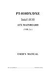
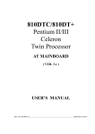
1
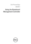
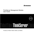
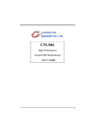
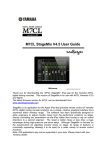
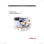
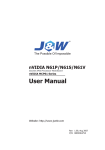
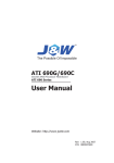
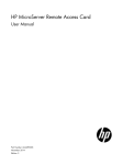
Troubleshooting Guide for
Cisco UCS E-Series Servers and the
Cisco UCS E-Series Network Compute Engine
February 18, 2015
This document provides troubleshooting information for Cisco UCS E-Series Servers (E-Series Servers)
and the Cisco UCS E-Series Network Compute Engine (NCE).
Note
Documentation is sometimes updated after original publication; therefore, review the documentation on
Cisco.com for any updates.
Contents
This guide contains the following sections:
•
Link to Product Documentation, page 2
•
Types of E-Series Servers and NCEs, page 2
•
General Troubleshooting, page 2
•
VMware License Troubleshooting, page 6
•
Microsoft Windows Installation Troubleshooting, page 6
•
Host Login and CIMC Login Troubleshooting, page 7
•
Determining Version Information, page 8
•
Cisco IOS and CIMC CLI Configuration Troubleshooting, page 12
•
LED, DIMM, Video Port, USB Port, and CD/DVD Troubleshooting, page 14
•
KVM Troubleshooting, page 17
•
Storage Troubleshooting, page 18
•
SNMP Troubleshooting, page 23
Americas Headquarters:
Cisco Systems, Inc., 170 West Tasman Drive, San Jose, CA 95134-1706 USA
Link to Product Documentation
•
Diagnostics Troubleshooting, page 24
•
Collecting Technical Support Data, page 24
Link to Product Documentation
For links to the all Cisco UCS E-Series Servers and the Cisco UCS E-Series Network Compute Engine
documents, see the Documentation Guide for Cisco UCS E-Series Servers.
Types of E-Series Servers and NCEs
Figure 1
Types of E-Series Servers and NCEs
Double-Wide E-Series Server
SM E-Series NCE
EHWIC E-Series NCE
391749
Single-Wide E-Series Server
General Troubleshooting
Cannot Access the E-Series Server or NCE, page 3
•
CIMC Hangs, page 3
•
Cannot Download the Host Image, page 4
•
Cannot Power on the E-Series Server, page 4
•
Recovering From a Corrupted CIMC Firmware Image, page 5
•
Recovering From a Faulty SD Drive, page 5
•
Recovering From a Corrupted File System, page 5
•
Verifying and Upgrading to the Latest Firmware Image, page 5
Troubleshooting Guide for Cisco UCS E-Series Servers and the Cisco UCS E-Series Network Compute Engine
2
OL-26447-04
General Troubleshooting
Cannot Access the E-Series Server or NCE
See the “Troubleshooting E-Series Server or NCE Access Issues” section in the “Firmware
Management” chapter in the CLI Configuration Guide for Cisco UCS E-Series Servers and the Cisco
UCS E-Series Network Compute Engine, Release 2.x.
CIMC Hangs
To resolve this problem, do the following:
•
Use IPMI to reboot CIMC. If using IPMI does not resolve the problem, power cycle the E-Series
Server.
•
Verify that there is an SD card in the SD0 card slot. The SD card in the SD0 card slot contains the
CIMC software and should always be present.
Figure 2 shows the location of the SD0 card slot in a single-wide E-Series Server.
Figure 2
Single-Wide E-Series Server
345206
SD0 Card Slot
Figure 3 shows the location of the dual SD card slots in a double-wide E-Series Server.
The SD0 card is the lower card, located in the bottom SD card slot.
Note
Figure 3
Front Panel of the Double-Wide E-Series Server
HDD2
UCS-EXXX-K9-MX
MIC
GE3
RST
D0F
D2F
M1
D0A
D2A
M2
D1F
ACT
HOT
D1A
STS
HDD1
1
1
9
VGA
SERIAL
0
SD1
SD0
GE2
IMC
HDD0
EN
345207
PWR
M0
Dual SD Card Slots
and Cover
Troubleshooting Guide for Cisco UCS E-Series Servers and the Cisco UCS E-Series Network Compute Engine
OL-26447-04
3
General Troubleshooting
•
Power down the E-Series Server to check whether the SD card has come out of the slot. If it has,
reinsert the SD card. Do the following:
– If the E-Series Server is installed in a Cisco 3900 series router, use the hw-module sm slot
oir-stop command to power down the server, reinsert the SD card, and then use the hw-module
sm slot oir-start command to start the server.
– If the E-Series Server is installed in a Cisco 2900 series router, power cycle the router.
Note
Do not remove the SD card when the system is in operation.
Cannot Download the Host Image
To resolve this problem, verify the following:
•
The FTP server on which you want to download the host image is running.
•
The FTP server path to the image files is correct.
Cannot Power on the E-Series Server
To resolve this problem, clear the server's BIOS CMOS memory using the CIMC GUI or the CIMC CLI:
•
Clearing the BIOS CMOS Using the CIMC GUI, page 4
•
Clearing the BIOS CMOS Using the CIMC CLI, page 5
Clearing the BIOS CMOS Using the CIMC GUI
Before You Begin
•
Log into the CIMC GUI as a user with admin privileges.
•
Power off the server.
Procedure
Step 1
In the Navigation pane, click the Server tab.
Step 2
On the Server tab, click BIOS.
Step 3
In the Actions area, click Clear BIOS CMOS.
Step 4
In the confirmation window, click OK.
Troubleshooting Guide for Cisco UCS E-Series Servers and the Cisco UCS E-Series Network Compute Engine
4
OL-26447-04
General Troubleshooting
Clearing the BIOS CMOS Using the CIMC CLI
Procedure
Step 1
Enter the BIOS command mode. Use the scope bios command:
Server# scope bios
Step 2
Clear the BIOS CMOS memory. Use the clear cmos command:
Server /bios # clear-cmos
This operation will clear the BIOS CMOS.
Note: Server should be in powered off state to clear CMOS.
Step 3
At the confirmation prompt, enter y to confirm
Continue?[y|N] y
Recovering From a Corrupted CIMC Firmware Image
See the “Troubleshooting E-Series Server or NCE Access Issues” section in the “Firmware
Management” chapter in the CLI Configuration Guide for Cisco UCS E-Series Servers and the Cisco
UCS E-Series Network Compute Engine, Release 2.x.
Recovering From a Faulty SD Drive
See the “Troubleshooting E-Series Server or NCE Access Issues” section in the “Firmware
Management” chapter in the CLI Configuration Guide for Cisco UCS E-Series Servers and the Cisco
UCS E-Series Network Compute Engine, Release 2.x.
Recovering From a Corrupted File System
See the “Troubleshooting E-Series Server or NCE Access Issues” section in the “Firmware
Management” chapter in the CLI Configuration Guide for Cisco UCS E-Series Servers and the Cisco
UCS E-Series Network Compute Engine, Release 2.x.
Verifying and Upgrading to the Latest Firmware Image
Use the Cisco Host Upgrade Utility to verify and upgrade to the latest firmware image. See the Host
Upgrade Utility Guide for Cisco UCS E-Series Servers and the Cisco UCS E-Series Network Compute
Engine.
Troubleshooting Guide for Cisco UCS E-Series Servers and the Cisco UCS E-Series Network Compute Engine
OL-26447-04
5
VMware License Troubleshooting
VMware License Troubleshooting
•
Cannot Apply VMware FL-SRE-V-HOST License, page 6
Cannot Apply VMware FL-SRE-V-HOST License
This problem occurs if you are using more than 32 GB of RAM with VMware vSphere Hypervisor™ 5.x.
To resolve this problem, reduce the RAM to 32 GB or less, or upgrade your license to
FL-SRE-V-HOSTVC.
Microsoft Windows Installation Troubleshooting
•
VMware Boots After Microsoft Windows Installation, page 6
•
Microsoft Windows Installation Displays VMware Partitions, page 6
VMware Boots After Microsoft Windows Installation
This problem occurs if you had first installed VMware, and then installed Microsoft Windows. To
resolve this problem, do the following:
1.
Change the state of the physical drive to JBOD. See the “Changing the Physical Drive State” section
in the configuration guides for the version of the CIMC that you are using.
2.
Configure RAID to clear partitions. See the “Configuring RAID Using the CIMC GUI” section in
the configuration guides for the version of the CIMC that you are using.
The configuration guides are available at:
http://www.cisco.com/c/en/us/support/servers-unified-computing/ucs-e-series-servers/products-ins
tallation-and-configuration-guides-list.html.
Microsoft Windows Installation Displays VMware Partitions
During the Microsoft Windows installation, the “Where do you want to install Windows” dialog box
appears (see Figure 4), which displays partitions that were previously created by VMware. This dialog
box also displays the following warning message:
Warning: Windows Cannot be Installed to Disk x Partition x.
To resolve this problem, clear the old partitions by clicking Drive options (advanced), and then resume
with the Microsoft Windows installation.
Troubleshooting Guide for Cisco UCS E-Series Servers and the Cisco UCS E-Series Network Compute Engine
6
OL-26447-04
Host Login and CIMC Login Troubleshooting
Figure 4
Where Do You Want to Install Windows Dialog Box
Host Login and CIMC Login Troubleshooting
•
Cannot Session into the E-Series Server (Host), page 7
•
Cannot Session into CIMC with Active Directory Authentication, page 8
Cannot Session into the E-Series Server (Host)
The ucse slot session host command does not allow you to log into the E-Series Server. To resolve this
problem, do the following:
Procedure
Step 1
Verify that the line speed value is 9600. Use the show line command to verify the line speed value:
Router# show
Tty Line Typ
*
0
0
1
1
2
2
131 131
Step 2
line
Tx/Rx
CTY
AUX
TTY
TTY
A Modem
9600/9600 9600/9600 9600/9600
Roty AccO AccI
-
Uses
-
Noise Overruns Int
9
0
0/0
0
0
0/0
0
0
0/0
-
If the line speed value is correct, verify that the Baud rate value is 9.6K and the terminal type is
compatible. Use the show detail command from /bios/server-management to verify the Baud rate and
terminal type:
router# ucse 2 session imc
CIMC# scope bios/server-management
CIMC /bios/server-management # show detail
Set-up parameters:
Assert NMI on PERR: Disabled
Assert NMI on SERR: Disabled
Baud rate: 9.6k
Console redirection: Serial Port A
FRB2 Enable: Enabled
Flow Control: None
Troubleshooting Guide for Cisco UCS E-Series Servers and the Cisco UCS E-Series Network Compute Engine
OL-26447-04
7
Determining Version Information
OS Boot Watchdog Timer: Disabled
OS Boot Watchdog Timer Policy: Do Nothing
Power Restore Policy: Power On
Terminal type: PC-ANSI
Step 3
Verify that the Enabled option in Serial over LAN (sol) is configured as no. Use the show detail
command from /sol to verify the sol configuration:
CIMC# scope sol
CIMC /sol # show detail
Serial Over LAN:
Enabled: no
Baud Rate(bps): 9600
Cannot Session into CIMC with Active Directory Authentication
This problem occurs if you did not provide your full domain name followed by your username. To
resolve this problem, provide your full domain name followed by your username. For example:
CIMC login: cert.cisco.com\adadmin
Password:
PING 172.19.159.52 (172.19.159.52): 56 data bytes
64 bytes from 172.19.159.52: seq=0 ttl=128 time=0.000 ms
--- 172.19.159.52 ping statistics --1 packets transmitted, 1 packets received, 0% packet loss
round-trip min/avg/max = 0.000/0.000/0.000 ms
Determining Version Information
•
Determining the Cisco IOS Version Installed on the Router, page 9
•
Determining Information About the E-Series Server Through Diagnostics, page 9
•
Determining the Hardware Version of the E-Series Server or the NCE, page 9
•
Determining the BIOS Version Installed on the E-Series Server or the NCE, page 10
•
Determining the CIMC Version Installed on the E-Series Server or the NCE, page 11
•
Determining the LSI Firmware Version—Applicable on CIMC Release 1.x, page 12
•
Determining the LSI Firmware Version—Applicable on CIMC Release 2.x, page 12
Troubleshooting Guide for Cisco UCS E-Series Servers and the Cisco UCS E-Series Network Compute Engine
8
OL-26447-04
Determining Version Information
Determining the Cisco IOS Version Installed on the Router
Note
•
The supported Cisco IOS software version on E-Series Servers is 15.2(4)M and later versions. For
details, see the “Verifying the Router, E-Series Server, and Cisco IOS Software Version
Compatibility” section in the getting started guide for the version of the CIMC that you are using.
The getting started guides are available at:
http://www.cisco.com/c/en/us/support/servers-unified-computing/ucs-e-series-servers/products-ins
tallation-guides-list.html.
•
The Cisco 2921 and 2951 series routers support 4-core only.
To determine the Cisco IOS version, use the show version or the show inventory command from the
router:
Router> show version
Cisco CISCO3945-CHASSIS (revision 1.0) with C3900-SPE150/K9 with 1048576K/63488K bytes of
memory.
1 cisco UCSE Module(s)
Router> show inventory
NAME: “UCSE Server Module on Slot 4", DESCR: “UCSE Server Module”
PID: UCS-E140D-M1/K9
, VID: V00 , SN: FOC16161F5E
Determining Information About the E-Series Server Through Diagnostics
To determine the type of E-Series Server that is installed in the router and in which slot it is installed,
use the show diag command from the router:
Router> show diag
Slot 4:
UCSE Double Wide Module Port adapter, 2 ports
Port adapter is analyzed
Port adapter insertion time 4d18h ago
Product (FRU) Number
: UCS-E140D-M1/K9
Determining the Hardware Version of the E-Series Server or the NCE
You can determine the hardware version of the E-Series Server or the NCE from the CIMC GUI or from
the CIMC CLI:
•
Determining the Hardware Version of the E-Series Server or the NCE from the CIMC GUI, page 10
•
Determining the Hardware Version of the E-Series Server or the NCE from the CIMC CLI, page 10
Troubleshooting Guide for Cisco UCS E-Series Servers and the Cisco UCS E-Series Network Compute Engine
OL-26447-04
9
Determining Version Information
Determining the Hardware Version of the E-Series Server or the NCE from the CIMC GUI
Procedure
Step 1
In the Navigation pane, click the Server tab.
Step 2
On the Server tab, click Summary. The Server Summary page appears.
Step 3
In the Cisco Integrated Management Controller (CIMC) Information area, the hardware version of
the E-Series Server is displayed in the CPLD Version and the Hardware Version fields.
Determining the Hardware Version of the E-Series Server or the NCE from the CIMC CLI
Enter the following commands:
Server# scope cimc
Server/cimc # scope firmware
Server/cimc/firmware # show detail
Firmware Image Information:
Update Stage: NONE
Update Progress: 0%
Current FW Version: 2.3(1.20140818121921)
FW Image 1 Version: 2.3(1.20140818121921)
FW Image 1 State: RUNNING ACTIVATED
FW Image 2 Version: 2.3(1.20140818113904)
FW Image 2 State: BACKUP INACTIVATED
Boot-loader Version: 2.3(1.20140818121921).33
CPLD Version: 0.62
Hardware Version: 0
Determining the BIOS Version Installed on the E-Series Server or the NCE
You can determine the BIOS version of the E-Series Server or the NCE from the CIMC GUI or from the
CIMC CLI.
•
Determining the BIOS Version Installed on the E-Series Server or the NCE from the CIMC GUI,
page 10
•
Determining the BIOS Version Installed on the E-Series Server or the NCE from the CIMC CLI,
page 11
Determining the BIOS Version Installed on the E-Series Server or the NCE from the CIMC GUI
To determine the BIOS version of the E-Series Server, do the following from the CIMC GUI.
Procedure
Step 1
In the Navigation pane, click the Server tab.
Step 2
On the Server tab, click BIOS. The BIOS page appears.
Step 3
In the BIOS Properties area, the BIOS version is displayed in the Running Version field.
Troubleshooting Guide for Cisco UCS E-Series Servers and the Cisco UCS E-Series Network Compute Engine
10
OL-26447-04
Determining Version Information
Determining the BIOS Version Installed on the E-Series Server or the NCE from the CIMC CLI
Enter the following commands:
Server # scope bios
Server /bios # show detail
BIOS:
BIOS Version: "UCSES.1.5.0.1 (Build Date: 02/14/2013)"
Boot Order: CDROM:Virtual-CD,HDD:RAID,EFI
FW Update/Recovery Status: None, OK
Active BIOS: main
Determining the CIMC Version Installed on the E-Series Server or the NCE
You can determine the CIM version installed on the E-Series Server or the NCE from the CIMC GUI or
from the CIMC CLI.
•
Determining the CIMC Version Installed on the E-Series Server or the NCE from the CIMC GUI,
page 11
•
Determining the CIMC Version Installed on the E-Series Server or the NCE from the CIMC CLI,
page 11
Determining the CIMC Version Installed on the E-Series Server or the NCE from the CIMC GUI
To determine the CIMC version of the E-Series Server, do the following from the CIMC GUI.
Procedure
Step 1
In the Navigation pane, click the Admin tab.
Step 2
On the Admin tab, click Firmware Management. The Firmware Management page appears.
Step 3
In the CIMC Firmware area, the CIMC version is displayed in the Running Version field.
Determining the CIMC Version Installed on the E-Series Server or the NCE from the CIMC CLI
Enter the following commands:
Server# scope cimc
Server/cimc # scope firmware
Server/cimc/firmware # show detail
Firmware Image Information:
Update Stage: NONE
Update Progress: 0%
Current FW Version: 2.3(1.20140818121921)
FW Image 1 Version: 2.3(1.20140818121921)
FW Image 1 State: RUNNING ACTIVATED
FW Image 2 Version: 2.3(1.20140818113904)
FW Image 2 State: BACKUP INACTIVATED
Boot-loader Version: 2.3(1.20140818121921).33
CPLD Version: 0.62
Hardware Version: 0
Troubleshooting Guide for Cisco UCS E-Series Servers and the Cisco UCS E-Series Network Compute Engine
OL-26447-04
11
Cisco IOS and CIMC CLI Configuration Troubleshooting
Determining the LSI Firmware Version—Applicable on CIMC Release 1.x
To determine the LSI firmware version, do the following from the CIMC GUI.
Procedure
Step 1
In the Navigation pane, click the Server tab.
Step 2
On the Server tab, click Inventory. The Inventory page appears.
Step 3
Click the Storage tab.
Step 4
In the Storage Adapters area, the LSI firmware information is displayed in the Firmware Package
Build column.
Determining the LSI Firmware Version—Applicable on CIMC Release 2.x
Note
This procedure is applicable to E-Series Servers and the SM E-Series NCE. This section is not applicable
to the EHWIC E-Series NCE.
To determine the LSI firmware version, do the following from the CIMC GUI.
Procedure
Step 1
In the Navigation pane, click the Server tab.
Step 2
On the Server tab, click RAID. The Storage Cards page appears.
Step 3
In the Storage Adapters area, the LSI firmware information is displayed in the Firmware Package
Build column.
Cisco IOS and CIMC CLI Configuration Troubleshooting
•
Cisco IOS Configurations Not Applied to CIMC, page 12
•
Cannot View Latest Configuration Changes in CIMC, page 13
•
Cannot Commit CIMC CLI Configuration Changes, page 13
Cisco IOS Configurations Not Applied to CIMC
This problem occurs if Lock IOS Configuration Changes is enabled in CIMC. Use the CIMC GUI or
the CIMC CLI to resolve this problem.
•
Enabling Cisco IOS Configuration Changes to Be Applied to CIMC Using the GUI, page 13
•
Enabling Cisco IOS Configuration to Be Applied to CIMC Using the CLI, page 13
Troubleshooting Guide for Cisco UCS E-Series Servers and the Cisco UCS E-Series Network Compute Engine
12
OL-26447-04
Cisco IOS and CIMC CLI Configuration Troubleshooting
Enabling Cisco IOS Configuration Changes to Be Applied to CIMC Using the GUI
To enable Cisco IOS configuration changes to be applied to CIMC, do the following from the CIMC
GUI.
Procedure
Step 1
In the Navigation pane, click the Server tab.
Step 2
On the Server tab, click Summary. The Server Summary page appears.
Step 3
From the Server Summary page, click the Lock IOS Configuration Changes button to unlock it.
Enabling Cisco IOS Configuration to Be Applied to CIMC Using the CLI
Use the set ios-lockout unlocked command to enable the Cisco IOS configuration changes to be applied
to CIMC:
Server /chassis # set ios-lockout unlocked
Server /chassis *# commit
Server /chassis # show detail
Chassis:
Power: off
Power Button: unlocked
IOS Lockout: unlocked
Serial Number: FOC16161F5E
Product Name: E140D
PID : UCS-E140D-M1/K9
UUID: 1255F7F0-0F16-0000-E5A5-05EAA6AF20B5
Description:
Cannot View Latest Configuration Changes in CIMC
To resolve this problem, after making changes to the configuration, click Refresh.
Cannot Commit CIMC CLI Configuration Changes
This problem occurs under the following conditions:
•
If you assigned a static IP address for CIMC, and then left the values of DHCP Enabled and
DNS-use-DHCP as Yes. To resolve this problem, change the value to No, and then assign the static
IP address:
Server
Server
Server
Server
•
/cimc/network
/cimc/network
/cimc/network
/cimc/network
# set dns-use-dhcp no
*# set dhcp-enabled no
*# set v4-addr 192.168.100.78
*# commit
If you made configuration changes in one scope, and then tried to commit those changes from
another scope.
The commit command must be used to commit changes that are made within the same scope. If you
try to use the commit command to submit changes made in a different scope, an error message
displays. To resolve this problem, redo and recommit the changes in the same scope.
Troubleshooting Guide for Cisco UCS E-Series Servers and the Cisco UCS E-Series Network Compute Engine
OL-26447-04
13
LED, DIMM, Video Port, USB Port, and CD/DVD Troubleshooting
LED, DIMM, Video Port, USB Port, and CD/DVD Troubleshooting
•
LED Color Displays Amber—Applicable to the E-Series Servers and the SM E-Series NCE, page 14
•
DIMM Not Functioning, page 14
•
Front Panel Video Port Does Not Work—Applicable to the E-Series Servers and the SM E-Series
NCE, page 15
•
Front Panel USB Port Does Not Work, page 15
•
Cannot Boot from the External CD/DVD Device, page 16
•
Configuring the Boot Order Using the BIOS Setup Menu, page 16
LED Color Displays Amber—Applicable to the E-Series Servers and the SM
E-Series NCE
At run time or during server start-up, the post diagnostic tests check the CPU, DIMM, and HDD. If any
failure occurs, the failure notifications are sent to the system event logs (SEL). You can view these
notification in the SEL or in the output of the show tech-support command. When errors occur, an
amber diagnostic LED displays next to the failed component. To resolve the DIMM and HDD problem,
power down the E-Series Server or SM E-Series NCE, and then verify if the DIMMs and the hard drives
are installed correctly.
Procedure
Step 1
If the E-Series Server or SM E-Series NCE is installed into a 3900 series router, power off the server
using the
hw-module sm slot oir stop command; otherwise, power down the router.
Step 2
Remove the server.
Step 3
Reinsert the DIMMs or hard drives as appropriate.
Step 4
Reinsert the server into the router.
Step 5
If the router was powered down, power it on.
DIMM Not Functioning
To resolve this problem, do the following:
•
Make sure that the DIMMs are installed and are of the same capacity. Do the following:
– In the Navigation pane, click the Server tab.
– On the Server tab, click Inventory. The Inventory page appears.
– Click the Memory tab. The Capacity column in the Memory Details area allows you to
determine the capacity of the DIMMs and whether the DIMM is installed or not.
Verify that the value in the Capacity column for the DIMMs is the same.
If the DIMMs are installed, the Capacity column displays a numerical value; otherwise, it
displays Not Installed.
Troubleshooting Guide for Cisco UCS E-Series Servers and the Cisco UCS E-Series Network Compute Engine
14
OL-26447-04
LED, DIMM, Video Port, USB Port, and CD/DVD Troubleshooting
•
Check whether there are memory related system event logs. Do the following:
– In the Navigation pane, click the Server tab.
– On the Server tab, click System Event Log. The System Event Log page appears.
– In the Description column, look for events that start with FRU_RAM xxx.
•
Check if the DIMM is supported on that server model.
– Single-Wide E-Series Server—Supports DDR3 1333MHz VLP UDIMM 1.5 V, 4 GB, and 8 GB
– Double-Wide E-Series Server—Supports DDR3 1333 MHz RDIMM 1.35 V, 4 GB, 8 GB and
16 GB
– Double-wide with PCIE support—Supports DDR3 1333 MHz RDIMM 1.35 V, 4 GB, 8 GB, and
16 GB
– EHWIC E-Series NCE—Supports DDR3 1333 MHz SODIMM, 4 GB, 8 GB, and 16GB
•
Check if the DIMM is correctly installed in the server slot, otherwise, remove and reinstall the
DIMM.
Front Panel Video Port Does Not Work—Applicable to the E-Series Servers and
the SM E-Series NCE
This problem occurs if the Enable Local Server Video checkbox is not checked. To resolve this
problem, do the following from the CIMC GUI.
Procedure
Step 1
In the Navigation pane, click the Server tab.
Step 2
On the Server tab, click Remote Presence.
Step 3
In the Remote Presence pane, click the Virtual KVM tab.
Step 4
In the vKVM Properties area, check the Enable Local Server Video checkbox.
Front Panel USB Port Does Not Work
The light on the device that is connected to the front panel USB port is off. This problem occurs if the
USB Port in the USB BIOS Settings is not enabled. To resolve this problem, do the following from the
CIMC GUI.
Procedure
Step 1
In the Navigation pane, click the Server tab.
Step 2
On the Server tab, click BIOS.
Step 3
In the Actions area, click Configure BIOS. The Configure BIOS Parameters dialog box appears.
Step 4
In the Configure BIOS Parameters dialog box, click the Advanced tab.
Troubleshooting Guide for Cisco UCS E-Series Servers and the Cisco UCS E-Series Network Compute Engine
OL-26447-04
15
LED, DIMM, Video Port, USB Port, and CD/DVD Troubleshooting
Step 5
Scroll down until you reach the USB BIOS Settings area.
Step 6
Verify if the USB Port 0 and USB Port 1 are enabled. If the ports are disabled, enable them.
Cannot Boot from the External CD/DVD Device
To resolve this problem, do the following:
•
Verify that the USB Port to which the CD/DVD device is connected to, is enabled. See Front Panel
USB Port Does Not Work, page 15.
•
Verify that the power current used by the CD/DVD device does not exceed 700mA. If it exceeds
700mA, the USB port to which the CD/DVD device is connected to, might not stay stable. The USB
port might go on or off; or might get disabled. To resolve this problem, try connecting the device to
an externally-powered USB hub.
•
Make sure that the CD/DVD ROM device is configured as the first boot device in the boot order
table. For procedure, See Configuring the Boot Order Using the BIOS Setup Menu, page 16.
•
Reboot the E-Series Server.
Configuring the Boot Order Using the BIOS Setup Menu
Use this procedure if you want the server to boot from an external bootable device, such as an USB or an
external CD ROM drive that is directly connected to the E-Series Server. Do the following from the CIMC
GUI.
Procedure
Step 1
In the Navigation pane, click the Server tab.
Step 2
On the Server tab, click Summary.
Step 3
From the Actions area, click Launch KVM Console. The KVM Console opens in a separate window.
Step 4
From the Server Summary page, click Power Cycle Server to reboot the server.
Step 5
When prompted, press F2 during bootup to access the BIOS setup menu. The Aptio Setup Utility
appears, which provides the BIOS setup menu option.
Step 6
Use the Right or Left arrow keys on your keyboard to select the Boot tab.
Step 7
Scroll down to the bottom of the page below the Boot Options Priority area. The following boot option
priorities are listed:
•
Floppy Drive BBS Priorities
•
Network Device BBS Priorities
•
Hard Drive BBS Priorities
•
CD/DVD ROM Drive BBS Priorities
Step 8
Use the Up or Down arrow keys on your keyboard to highlight the appropriate option.
Step 9
Press Enter to select the highlighted field.
Troubleshooting Guide for Cisco UCS E-Series Servers and the Cisco UCS E-Series Network Compute Engine
16
OL-26447-04
KVM Troubleshooting
Step 10
Choose the appropriate device as Boot Option 1.
Step 11
Press F4 to save changes and exit.
The Main tab of the BIOS setup displays the device that you configured as Boot Option 1.
KVM Troubleshooting
•
Cannot Mount vMedia, page 17
•
Cannot Launch vKVM—Error Message: Connection Failed, page 17
•
Occasionally KVM Does Not Launch, page 18
•
Cannot Launch Broadcom FCOE Configuration, page 18
Cannot Mount vMedia
This problem can occur if you have not enabled virtual media. To resolve this problem, do the following
from the CIMC GUI.
Procedure
Step 1
In the Navigation pane, click the Server tab.
Step 2
On the Server tab, click Remote Presence. The Remote Presence page appears.
Step 3
Click the Virtual Media tab, and in the Virtual Media Properties area, check the Enabled check box.
Step 4
If this does not solve the problem, do the following:
a.
Uncheck the Enabled checkbox, and then click Save Changes.
b.
Check the Enabled checkbox, and then click Save Changes.
Cannot Launch vKVM—Error Message: Connection Failed
If you try to launch vKVM through Proxy, you get a Connection Failed error message. To resolve this
problem, disable Proxy.
Troubleshooting Guide for Cisco UCS E-Series Servers and the Cisco UCS E-Series Network Compute Engine
OL-26447-04
17
Storage Troubleshooting
Occasionally KVM Does Not Launch
To resolve this problem, do the following:
Step 1
Restart your browser, and try again.
Step 2
Make sure that the Java version that is installed is at least 6.0.
Step 3
If this does not resolve the problem, clear the Java cache from the Java control panel.
Cannot Launch Broadcom FCOE Configuration
If Broadcom FCOE configuration does not launch when you press CTRl-S, reboot the E-Series Server
and try again.
Storage Troubleshooting
Note
The RAID feature is applicable to E-Series Servers and the SM E-Series NCE. The RAID feature is not
applicable to the EHWIC E-Series NCE.
•
Error Message: LSI OpROM: Battery Status: Not Present, page 18
•
Viewing Storage Event Logs, page 19
•
Determining the Current Boot Drive—Applicable to CIMC Release 1.x, page 19
•
Determining the Current Boot Drive—Applicable to CIMC Release 2.x, page 20
•
Mouse and Keyboard Use in LSI WebBIOS Flaky, page 20
•
When to Use LSI WebBIOS, page 20
•
Show Inventory Command Output Displays Unknown xxx Error Message, page 21
•
RAID Operation is Stuck, page 21
•
No Drives Available to Configure RAID, page 21
•
RAID Array Disappeared From the CIMC GUI, page 22
•
Physical Drives Changed State to Unconfigured Good, page 22
•
Cannot Access Secure Drives, page 22
•
Cannot Reconfigure Drives, page 23
Error Message: LSI OpROM: Battery Status: Not Present
Ignore this message.
Troubleshooting Guide for Cisco UCS E-Series Servers and the Cisco UCS E-Series Network Compute Engine
18
OL-26447-04
Storage Troubleshooting
Viewing Storage Event Logs
Note
This procedure is applicable to E-Series Servers and the SM E-Series NCE. This procedure is not applicable
to the EHWIC E-Series NCE.
To view storage event logs, do the following from the CIMC GUI.
Procedure
Step 1
In the Navigation pane, click the Admin tab.
Step 2
On the Admin tab, click CIMC Log. The CIMC Log page appears.
Step 3
In the Source column, look for the logs that begin with BMC:storage.
Determining the Current Boot Drive—Applicable to CIMC Release 1.x
Note
This procedure is applicable to E-Series Servers and the SM E-Series NCE. This procedure is not applicable
to the EHWIC E-Series NCE.
To determine which drive is bootable, do the following from the CIMC GUI.
Procedure
Step 1
In the Navigation pane, click the Server tab.
Step 2
On the Server tab, click Inventory. The Inventory page appears.
Step 3
Click the Storage tab.
Step 4
Click the Controller Info tab.
Step 5
In the Settings area, the current boot drive information is displayed in the Current Boot Drive field.
Troubleshooting Guide for Cisco UCS E-Series Servers and the Cisco UCS E-Series Network Compute Engine
OL-26447-04
19
Storage Troubleshooting
Determining the Current Boot Drive—Applicable to CIMC Release 2.x
Note
This procedure is applicable to E-Series Servers and the SM E-Series NCE. This procedure is not applicable
to the EHWIC E-Series NCE.
To determine which drive is bootable, do the following from the CIMC GUI.
Procedure
Step 1
In the Navigation pane, click the Server tab.
Step 2
On the Server tab, click RAID. The Storage Card page appears.
Step 3
Click the Controller Info tab.
Step 4
In the Settings area, the current boot drive information is displayed in the Current Boot Drive field.
Mouse and Keyboard Use in LSI WebBIOS Flaky
This is a known problem. To work around this problem, connect a physical mouse and keyboard.
When to Use LSI WebBIOS
Note
This section is applicable to E-Series Servers and the SM E-Series NCE. This section is not applicable to the
EHWIC E-Series NCE.
Use the LSI WebBIOS under the following conditions:
•
When the LSI warning message appears at OPROM, which requires drive configuration.
•
To configure RAID arrays with SED drives.
•
To change or remove security keys and pass phrase for SED.
•
To configure foreign SED drives.
•
To clear RAID configuration before installing a new operating system.
Troubleshooting Guide for Cisco UCS E-Series Servers and the Cisco UCS E-Series Network Compute Engine
20
OL-26447-04
Storage Troubleshooting
Show Inventory Command Output Displays Unknown xxx Error Message
Note
This error message is applicable to E-Series Servers and the SM E-Series NCE. This error message is not
applicable to the EHWIC E-Series NCE.
Symptom—When you enter the show inventory command, the server is not recognized and you get the
following error message:
Router> show inventory
NAME: “Unknown on Slot 4", DESCR: “Unknown”
PID: UCS-E140D-M1/K9
, VID: V00 , SN: FOC16161F5E
This problem occurs if you installed an unsupported version of Cisco IOS software. The supported Cisco
IOS software version on E-Series Servers is 15.2(4)M and later versions. For details, see the “Verifying
the Router, E-Series Server, and Cisco IOS Software Version Compatibility” section in the getting
started guide for the version of the CIMC that you are using. The getting started guides are available at:
http://www.cisco.com/c/en/us/support/servers-unified-computing/ucs-e-series-servers/products-installa
tion-guides-list.html.
RAID Operation is Stuck
Note
This section is applicable to E-Series Servers and the SM E-Series NCE. This section is not applicable to the
EHWIC E-Series NCE.
Symptom—After the rebuild, reconstruction, and consistency checks trigger, the RAID operation does
not proceed and remains at 0%, and the elapsed time displays 0 seconds.
This problem occurs because RAID operations rely on the memory of the host operating system to
function properly. To resolve this problem, verify if the operating system has booted. If it has not booted,
boot the operating system.
No Drives Available to Configure RAID
Note
This section is applicable to E-Series Servers and the SM E-Series NCE. This section is not applicable to the
EHWIC E-Series NCE.
Symptom—When you click Create to configure RAID, you notice that no drives are available in the
Select Drives area.
To resolve this problem, make sure that the state of the drive is unconfigured good. See “Changing the
Physical Drive State” section in the configuration guides for the version of the CIMC that you are using.
The configuration guides are available at:
http://www.cisco.com/c/en/us/support/servers-unified-computing/ucs-e-series-servers/products-installa
tion-and-configuration-guides-list.html.
Troubleshooting Guide for Cisco UCS E-Series Servers and the Cisco UCS E-Series Network Compute Engine
OL-26447-04
21
Storage Troubleshooting
RAID Array Disappeared From the CIMC GUI
Note
This section is applicable to E-Series Servers and the SM E-Series NCE. This section is not applicable to the
EHWIC E-Series NCE.
Symptom—CIMC GUI does not show the RAID array that was originally present in the system.
This problem can occur if during bootup, at LSI OpROM, you concurrently entered wrong or empty pass
phrase three times. Because of the “BIOS Continue on Error” feature, the booting process continues, but
the drives cannot be accessed.
To resolve this problem, do the following:
1.
Reboot the system, and then enter the correct pass phrase.
2.
From LSI WebBIOS, configure the new pass phrase or remove security.
Physical Drives Changed State to Unconfigured Good
Note
This section is applicable to E-Series Servers and the SM E-Series NCE. This section is not applicable to the
EHWIC E-Series NCE.
This problem can occur if during bootup, at LSI OpROM, you concurrently entered wrong or empty pass
phrase three times. Because of the “BIOS Continue on Error” feature, the booting process continues, but
the drives cannot be accessed.
To resolve this problem, do the following:
1.
Reboot the system, and then enter the correct pass phrase.
2.
From LSI WebBIOS, configure the new pass phrase or remove security.
Cannot Access Secure Drives
Note
This section is applicable to E-Series Servers and the SM E-Series NCE. This section is not applicable to the
EHWIC E-Series NCE.
This problem can occur if during bootup, at LSI OpROM, you concurrently entered wrong or empty pass
phrase three times. Because of the “BIOS Continue on Error” feature, the booting process continues, but
the drives cannot be accessed.
To resolve this problem, do the following:
1.
Reboot the system, and then enter the correct pass phrase.
2.
From LSI WebBIOS, configure the new pass phrase or remove security.
Troubleshooting Guide for Cisco UCS E-Series Servers and the Cisco UCS E-Series Network Compute Engine
22
OL-26447-04
SNMP Troubleshooting
Cannot Reconfigure Drives
Note
This section is applicable to E-Series Servers and the SM E-Series NCE. This section is not applicable to the
EHWIC E-Series NCE.
This problem can occur if during bootup, at LSI OpROM, you concurrently entered wrong or empty pass
phrase three times. Because of the “BIOS Continue on Error” feature, the booting process continues, but
the drives cannot be accessed.
To resolve this problem, do the following:
1.
Reboot the system, and then enter the correct pass phrase.
2.
From LSI WebBIOS, configure the new pass phrase or remove security.
SNMP Troubleshooting
•
SNMP Does Not Respond, page 23
•
SNMP Not Sending Traps, page 23
SNMP Does Not Respond
To resolve this problem, do the following from the CIMC GUI.
Procedure
Step 1
In the Navigation pane, click the Admin tab.
Step 2
On the Admin tab, click Communication Services. The Communication Services page appears.
Step 3
Click the SNMP tab.
Step 4
In the SNMP Properties area, make sure that the SNMP Enabled checkbox is checked.
SNMP Not Sending Traps
To resolve this problem, do the following:
Step 1
Make sure you have enabled SNMP. See SNMP Does Not Respond, page 23.
Step 2
Configure SNMP Trap Settings. See the “Configuring SNMP Trap Settings” section in the configuration
guides for the version of the CIMC that you are using. The configuration guides are available at:
http://www.cisco.com/c/en/us/support/servers-unified-computing/ucs-e-series-servers/products-installa
tion-and-configuration-guides-list.html.
Troubleshooting Guide for Cisco UCS E-Series Servers and the Cisco UCS E-Series Network Compute Engine
OL-26447-04
23
Diagnostics Troubleshooting
Diagnostics Troubleshooting
•
Running Diagnostic Tests, page 24
•
Show Diag Command Displays Unknown Port Adapter Error Message, page 24
Running Diagnostic Tests
See the “Diagnostic Tests” chapter in the configuration guides for the version of the CIMC that you are
using. The configuration guides are available at:
http://www.cisco.com/c/en/us/support/servers-unified-computing/ucs-e-series-servers/products-installa
tion-and-configuration-guides-list.html.
Show Diag Command Displays Unknown Port Adapter Error Message
Symptom—When you enter the show diag command, the server is not recognized and you get the
following error message:
Router> show diag
Unknown (type 1889) Port adapter
Port adapter is disabled
Product (FRU) Number
: UCS-E140D-M1/K9
This problem occurs if you installed an unsupported version of Cisco IOS software. The supported Cisco
IOS software version on E-Series Servers is 15.2(4)M and later versions. For details, see the “Verifying
the Router, E-Series Server, and Cisco IOS Software Version Compatibility” section in the getting
started guide for the version of the CIMC that you are using. The getting started guides are available at:
http://www.cisco.com/c/en/us/support/servers-unified-computing/ucs-e-series-servers/products-installa
tion-guides-list.html.
Collecting Technical Support Data
You can use the CIMC GUI or the CIMC CLI to collect technical support data. Perform this task when
requested by the Cisco Technical Assistance Center (TAC). This utility creates a summary report
containing configuration information, logs and diagnostic data that will help TAC in troubleshooting and
resolving a technical issue.
•
Collecting Technical Support Data Using the CIMC GUI, page 25
•
Collecting Technical Support Data Using the CIMC CLI, page 25
Troubleshooting Guide for Cisco UCS E-Series Servers and the Cisco UCS E-Series Network Compute Engine
24
OL-26447-04
Collecting Technical Support Data
Collecting Technical Support Data Using the CIMC GUI
To collect technical support data, do the following from the CIMC GUI:
Procedure
Step 1
In the Navigation pane, click the Admin tab.
Step 2
On the Admin tab, click Utilities.
Step 3
In the Actions area of the Utilities pane, click Export Technical Support Data.
Step 4
In the Export Technical Support Data dialog box, click the Export to a local file or the Export to
TFTP server radio button as appropriate.
Step 5
Click Export.
Note
Step 6
Technical support data collection takes a minimum of 3 minutes.
Provide the generated report file to Cisco TAC.
Collecting Technical Support Data Using the CIMC CLI
From the CIMC CLI, enter the following commands:
Server# scope cimc
Server /cimc # scope tech-support
Server /cimc/tech-support # set tftp-ip tftp_server_ip_address
Server /cimc/tech-support *# set path /user/user1/supportfile
Server /cimc/tech-support *# commit
Server /cimc/tech-support # start
Server /cimc/tech-support # show detail
Cisco and the Cisco logo are trademarks or registered trademarks of Cisco and/or its affiliates in the U.S. and other countries. To view a list of
Cisco trademarks, go to this URL: www.cisco.com/go/trademarks. Third-party trademarks mentioned are the property of their respective owners. The
use of the word partner does not imply a partnership relationship between Cisco and any other company. (1110R)
Any Internet Protocol (IP) addresses and phone numbers used in this document are not intended to be actual addresses and phone numbers. Any
examples, command display output, network topology diagrams, and other figures included in the document are shown for illustrative purposes only.
Any use of actual IP addresses or phone numbers in illustrative content is unintentional and coincidental.
© 2012 Cisco Systems, Inc. All rights reserved.
Troubleshooting Guide for Cisco UCS E-Series Servers and the Cisco UCS E-Series Network Compute Engine
OL-26447-04
25
Collecting Technical Support Data
Troubleshooting Guide for Cisco UCS E-Series Servers and the Cisco UCS E-Series Network Compute Engine
26
OL-26447-04