1
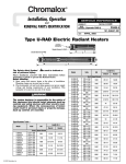
Chromalox
®
DIVISION
4
SECTION
DH
SALES
REFERENCE (Supersedes PF455-2)
PF455-3
161-562766-001
DATE
FEBRUARY, 2001
Chromalox Electric Airduct Heaters
with Fintube Heating Elements
W
W
Conduit
Entrance Plate
H
H
DHII
Integral Controls
Insert Type
Figure 1
DHIF
Integral Controls
Flanged Type
Figure 3
W
W
H
H
DHRF
Remote Controls
Flanged Type
Figure 4
DHRI
Remote Controls
Insert Type
Figure 2
GENERAL
These heaters are designed to be installed in either a horizontal
or vertical duct in one of the six positions shown in figure 16. The
heater is constructed with individual metal sheath fintube elements
mounted to a heavy gauge metal terminal box.
Due to the various options and materials available, check the
nameplate attached to the heater terminal box with the catalog
number designation system on page 7 before installing to insure
the heater you received conforms to your specification.
© 2010 Chromalox, Inc.
Please read these directions carefully to insure all limitations
are properly observed and all wiring and controls are properly
installed and connected.
IMPORTANT — Observe at least one complete heating cycle
operation before leaving the installation.
GENERAL
4. Installation near turns. (Refer to Figure 8). If heater must be
installed closer than 4 feet from the downstream side of a turn,
turning vanes must be installed in the turn. The turning vanes
will straighten out the air flow so it will be uniform over the
face of the heater.
Limitations: Ductwork must be in accordance with one of the following: Standards of the National Fire Protection Association for
the installation of Air Conditioning and Ventilating Systems of
other than Resident Type (Pamphlet 90A) or Residential Type
Warm Air Heating and Air Conditioning Systems (Pamphlet 90B).
Location: Chromalox Duct Heaters may be located anywhere in
the duct system.
2 Ft.
Min.
NOTE: The minimum distances shown are limitations. Wherever
possible, locate as far away from these limits as practical. In any
case, this distance with any required airflow correction must be
sufficient to accomplish even air flow at a velocity equal to, at
least, the minimum stated on the heater nameplate.
1. Installation near heat pump, central air conditioner, filters or
humidifier. (Refer to Figure 5).
Air
Duct Heater
Here or Here
Flo
w
4 Ft.
Min.
Duct Heater
Figure 8
Air
Flow
5. Installation with duct transitions in some air distribution systems, the duct heater may be considerably larger than the ductwork and the duct area must be increased by a sheet metal transition. The slope of the transformation piece on the upstream
side of the equipment is limited to 30° as indicated in Figure 9.
On the leaving side, the slope should not be more than 45°.
4 Ft.
Min.
Heat Pump,
Central Air Conditioner,
Filters or Humidifier
30"
Max.
45°
Figure 5
Duct Heater
2. Installation near air handler discharge. (Refer to Figure 6).
Air
Flow
Duct Heater
45°
30°
Air
Flow
Max.
4 Ft. Min.
4 Ft.
Min.
4 Ft. Min.
Figure 9
6. Do not insulate control or terminal box. (Refer to Figure 10).
Air Handler
Figure 6
External
Insulation
3. Installation in branch duct take-off. (Refer to Figure 7).
Air
Top of Duct
Flo
w
Duct Heater
Leave Control
Box Uninsulated
Figure 10
4 Ft. Min. Straight Section
Duct Heater
Figure 7
-2-
GENERAL
7. Installation in duct larger than heater. For installation where the
duct dimensions exceed the insert type heater dimensions, the
area beyond the heater dimensions must be filled with wire
mesh, expanded or perforated sheet metal of 50% open area as
shown in Figure 11. This will maintain a uniform air velocity
across the face of the duct.
Inner Baffle
Insert Type
Duct Heater
Flexible Duct
(Must be suitable
for 195°F)
Air ow
Fl
Perforated Metal
(50% Open Area)
Duct Heater
4 Ft.
Min.
Figure 12
10. Installation with dampers or filters. Maintain at least 4’ distance between duct heater and damper, filter frames, or other
similar obstructions. (Refer to Figure 13).
Remove Bracket and
Use Sheetmetal Screws
Thru Same Holes into Duct.
4 Ft.
Min.
Oversized Duct
Figure 11
Duct
Heater
Damper
8. Installation with flexible duct. Where a duct heater must be
installed near a flexible duct connection, be certain that a 4’
minimum distance between the duct heater and the flexible
connector exists and that the connector is suitable for 195°F
temperature. (Refer to Figure 12).
9. Do not install duct heater outdoors. Duct heaters cannot be
installed with rooftop equipment where they are exposed to the
weather.
Air Flow
Top of Duct
Figure 13
Clearance: Zero clearance between duct heater and combustible
materials such as wood is permissible. However, adequate clearance must be provided around terminal box for proper ventilation
and future service accessibility.
AIR FLOW
Flow through duct heater must never drop below the minimum
air velocity shown on duct heater nameplate. If the air handling
system includes filters, they must be cleaned whenever necessary
in order to maintain air flow above the minimum, otherwise poor
temperature control and discomfort will result.
If air flow is poorly distributed within the duct, deflector vanes
must be added to provide correction.
The minimum air velocities shown on the nameplate are not to
be considered average readings. Do not add various velocities
taken across the face of the duct, find an average value, and compare it to the minimum velocity shown on the heater nameplate.
The minimum air velocity refers to any point along the face of
the duct heater when checking duct velocities, no velocity can be
below that sown on the heater nameplate (remembering inlet air
temperature). Velocities are best checked with an anemometer, taking numerous readings along the horizontal and vertical centerline
of the duct heater at the location prior to installation or slightly up
stream from the heater after installation. (Refer to Figure 14).
Large ducts will require additional readings taken at locations in
addition to the centerline.
Duct Heater
low
F
Air
Velocity
Profile
Figure 14
Incoming Air Temperature: Incoming air temperature entering
the duct heater must not exceed 100°F.
Example: 500 FT./MIN. Minimum Air Velocity on Heater Nameplate.
Velocity
Profile
FT./MIN.
RIGHT:
600
500
700
600
900
700
600
500
Velocity
Profile
FT./MIN.
200x
400x
800
900
600
700
200x
300x
400x
WRONG:
9 4500 = 500 FT./MIN. AVERAGE
X – below 500 FT./MIN.
500 FT./MIN. MINIMUM
-3-
MOUNTING
Multiple Duct Heaters: Up to six duct heaters may be combined
into a heating bank as shown in Figure 15. When called for on
order, brackets will be furnished for fastening flange type duct
heaters together to form a bank. Heater will be coded for proper
assembly in the field.
Two to six duct heaters (with flange) may be installed in a horizontal or vertical duct.
Heaters must be mounted in the position designated by arrows
on the heater frame. (Refer to Figure 16).
The heater terminal box on vertical duct installations can be
located on any side of the duct but for horizontal duct installation
the terminal box must be on the side of the duct.
This heater is not intended for use in hazardous
atmospheres where flammable vapors, gases, liquids, or other combustible atmospheres are present as defined in the National Electric Code.
Failure to comply can result in explosion or fire.
Figure 15
Figure 16
HORIZONTAL DUCT — side terminal box
entry for style DHRI & DHRF heaters. Air
flow as shown. Install with this arrow up.
VERTICAL DUCT — side terminal box
entry for style DHRI & DHRF heaters. Air
flow as shown. Install with this arrow up.
Mounting Position 1
HORIZONTAL DUCT — side terminal
box entry for style DHRI & DHRF
heaters. Air flow as shown. Install with
this arrow up.
Mounting position 2
HORIZONTAL DUCT — Side terminal
box entry for style DHII & DHIF heaters.
Air flow as shown.
Install with this arrow up.
Mounting Position 4
HORIZONTAL DUCT — Side terminal
box entry for style DHII & DHIF heaters.
Air flow as shown.
Install with this arrow up.
Mounting Position 5
VERTICAL DUCT — Side terminal box
entry for style DHII & DHIF heaters. Air
flow as shown.
Install with this arrow up.
Mounting Position 6
-4-
Mounting Position 3
MOUNTING
Mounting Procedure — DHIF
(Flanged heaters with control box)
1. At heater location, cut out a section of duct, or a new construction lay out duct work to accommodate dimensions of
heater.
2. Form mounting flanges on cut edges of duct as shown in
Figure 17. Omit flange in side when terminal box overhangs.
3. Position heater in duct and attach duct lip to heater flanges with
sheet metal screws.
4. Attach control box to duct with sheet metal screws through the
mounting holes provided inside the control box.
NOTE: Where necessary, make provision to support weight of
heater. Any part of heater flange may be drilled for attaching hanger straps or duct.
5. Where necessary, joint between duct and heater flange may be
sealed with silicone gaskets or silicone sealant.
Double
Lip
Self-Adhesive Gasket
Supplied with Heater and
Installed by Customer
3/4"
3/4"
Duct
D
Control
Box
W
Sheet Metal
Screws
H
Mounting
Holes
H
Sheet Metal
Screws
W
Figure 17
Mounting Procedure DHII
(Insert heaters with control box)
1. Measure dimension “H” of duct heater (Figure 1) and mark the
duct with an outline for a rectangular hole with dimensions of
D-11/2”. The D-11/2” dimension is to be parallel to the direction
of air flow.
2. Increase D-11/2” slot to D by forming a 3/4” double lip on both
sides of the duct opening. (See Figure 18).
3. Slide heater into duct.
4. Attach control box to duct with sheet metal screws through the
mounting holes provided inside the control box and through
the brackets on the top and bottom of heater.
5. Where necessary, make provision to support weight of heater
and terminal box.
3/4"
Self-Adhesive Gasket
Supplied with Heater and
Installed by Customer
Double
Lip
Duct
D
W
Control
Box
Sheet Metal
Screws
H
Mounting
Holes
W
Figure 18
Self-Adhesive Gasket
Supplied with Heater and
Installed by Customer
Mounting Procedure — DHRF
(Flanged heaters with compact terminal box)
1. At heater location, cut out a section of duct, or on new construction lay out duct work to accommodate dimensions of
heater.
2. Form mounting flanges on cut edges of duct as shown in
Figure 19.
3. Position heater in duct and attach duct lip to heater flanges with
sheet metal screws.
NOTE: Where necessary, make provision to support weight of
heater. Any part of heater flange may be drilled for attaching hanger straps or duct.
4. Attach control box to duct with sheet metal screws through the
mounting holes provided inside the control box.
5. Where necessary, joint between duct and heater flange may be
sealed with silicone gasket or sealant.
Double
Lip
D
3/4"
W
3/4"
H
Duct
Figure 19
Mounting Procedure — DHRI
(Insert heaters with compact terminal box)
1. Measure dimension “H” of duct heater (Figure 2) and mark the
duct with an outline for a rectangular hole with dimensions of
D-11/2” x “H”. The D-11/2” dimension is to be parallel to the
direction of air flow.
2. Increase D-11/2” slot to “D” by forming a 3/4” double lip on each
side of the duct. (See Figure 19).
3. Slide heater into duct.
4. Attach control box to duct with sheet metal screws through the
mounting holes provided inside the control box and through
the brackets on the top and bottom of heater.
5. Where necessary, make provision to support weight of heater.
Self-Adhesive Gasket
Supplied with Heater and
Installed by Customer
Double
Lip
3/4"
W
H
Duct
D
Figure 20
-5-
H
WIRING
1. Connect heater only to the voltage, frequency and phase specified on the nameplate.
2. All wiring should be done according to local and National
Electric Codes.
3. Make supply connections to marked heater terminals using
wire suitable for 75°C. (Type RH-RW or equivalent).
4. Conduit attachment to heater:
a. Run conduit(s) to conduit entrance plate. (See Figure 1).
b. Mark plate where conduit(s) will enter plate.
c. Remove screws and plate.
d. Punch conduit entrance plate with a hole(s) to accommodate the required conduit(s).
e. Reinstall plate and install conduit(s) to plate.
Fan Interlock. The fan circuit must be interlocked with the
control circuit of the heater. Refer to the wiring diagram in the
heater terminal box.
Hazard of electrical shock. Any installation involving electric heaters must be grounded to earth to
eliminate shock hazard.
Control Ratings
Manual Limit Control
Pilot
Non-Inductive
Duty
Rating
Volts
Automatic Limit Control
Pilot
Non-Inductive
Duty
Rating
120
125 VA
3000 Watts
125 VA
3000 Watts
208
125 VA
5200 Watts
125 VA
5200 Watts
240
125 VA
6000 Watts
125 VA
6000 Watts
277
125 VA
6925 Watts
125 VA
6925 Watts
Hazard of severe shock. Disconnect all power to
heater before servicing.
WIRING DIAGRAM
The appropriate wiring diagram
will be supplied with each heater.
RENEWAL PARTS IDENTIFICATION
Typical DHIF Duct Heater
Conduit Entrance Plate
Main Disconnect
Transformer Fusing
Air Flow Switch
Transformer
Fintube Heating
Element
Static equalizers
(not shown) maintain
uniform air flow
across the heater
face when individual
fintubes are omitted.
Air Flow Switch Automatic and Manual Reset
(not shown)
Contactor
Fusing
Contact your local Chromalox Sales Office with Complete heater catalog number or part number.
-6-
CATALOG NUMBER DESIGNATION SYSTEM
OOOO- OOO- 00H
X
000W- X 00.00D- 000V 0 0P-
0 0 0 . 0 kW
000.0kW, (16kW/Ft.2 MAX.)
Phase: 1P = Single Phase’ 3P = Three Phase
0 = Number of circuits
000V = Heater voltage (up thru 600V)
00.00 = Depth of heater frame in inches
(06.50 min. – 36.00 max.)
000W = Width of duct in inches (08 thru 120)
00H = Height of duct in inches (06 thru 40)
Terminal box construction and terminal box and frame material:
GPA = General purpose terminal box and all aluminized steel construction
GPP = General purpose terminal box and all painted steel construction
GPZ = General purpose terminal box and all plated steel construction
GPS = General purpose terminal box and all stainless steel construction
DPA = Drip proof terminal box and aluminized steel construction
DPP = Drip proof terminal box and painted steel construction
DPZ = Drip proof terminal box and plated steel construction
DPS = Drip proof terminal box and stainless steel construction
General style:
DHRI = Duct heater, remote controls, insert type
DHRF = Duct heater, remote controls, flanged type
DHII = Duct heater, integral controls, insert type
DHIF = Duct heater, integral controls, flanged type
0MP-
OO OO O -
OOO000OO
Disconnecting Means:
ND = Nonfused disconnect switch (200A max.)
FD = Fused disconnect switch (48A max.)
TB = Terminal block (200A max.), disconnect switch by others
Control circuit voltage: 000 = 120, 208, 240, or 277V
Control circuit power supply:
T = Control circuit by integral transformer (120V Sec. Only)
R = Remote control circuit by customer (120, 208, 240, or 277V)
Fan interlock method:
AS = Air flow switch
FI = Fan interlock relay
FD = Fan interlock relay with fan delay
Heating element termination:
M = Threaded terminals with mica insulation
R = Threaded terminals with ceramic insulation (480V max.)
H = Hermetic seals (480V max.)
Method of attaching heating element to heater frame:
WA = Painted steel fin and sheath
GW = Mounting washer staked to element sheath with gasket
BF = Brass fitting with gasket
SS = Stainless steel fin and sheath
Sheath, fin, and finish of heating element:
PS = Painted steel fin and sheath
MO = Monel fin and sheath
SS = Stainless steel fin and sheath
Mounting position of heater:
1MP = See Figure 16 on page
2MP = See Figure 16 on page
3MP = See Figure 16 on page
4MP = See Figure 16 on page
5MP = See Figure 16 on page
6MP = See Figure 16 on page
4,
4,
4,
4,
4,
4,
mounting
mounting
mounting
mounting
mounting
mounting
position
position
position
position
position
position
-7-
1
2
3
4
5
6
Limited Warranty:
Please refer to the Chromalox limited warranty applicable to this product at
http://www.chromalox.com/customer-service/policies/termsofsale.aspx.
2150 N. RULON WHITE BLVD., OGDEN, UT 84404
Phone: 1-800-368-2493
www.chromalox.com