1
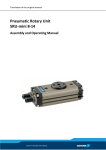
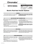
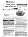
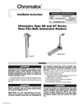
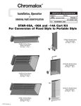
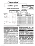
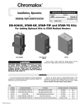
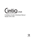
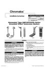
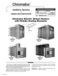
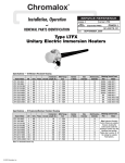
Installation, Operation
4
and
CHTV
PQ431
(Supersedes PQ431)
RENEWAL PARTS IDENTIFICATION
161-058058-001
JULY, 1983
Type CHTV Horizontal Vaporizers for Dowtherm®,
Therminol® and Other Organic Fluids
Manufacturing
Data –
(Temperatures to 750°F at 150 psi, 15 kW thru 300 kW)
System Model Number and Rating . . . . . . . . . . . . . . . . . . . . . . . . . . . . . . . . . . . . . . . . . . . . . . . . . . . . . . . . System Serial Number . . . . . . . . . . . . . . . . . . . . . . . . . . . . . . . . . . . .
Customer’s Name . . . . . . . . . . . . . . . . . . . . . . . . . . . . . . . . . . . . . . . . . . . . . . . . . . . . . . . . . . . . . . . . . . . . . Customer’s Order Number . . . . . . . . . . . . . . . . . . . . . . . . . . . . . . . . .
National Board Number . . . . . . . . . . . . . . . . . . . . . . . . . . . . . . . . . . . . . . . . . . . . . . . . . . . . . . . . . . . . . . . . Date . . . . . . . . . . . . . . . . . . . . . . . . . . . . . . . . . . . . . . . . . . . . . . . . . .
Specifications & Dimensions
Ampere*
Model Number
Standard
NEMA I
Oil &
Dust Tight
NEMA XII
Weatherresistant
NEMA IV
Dimensions
(In.)
Weight
(Lbs.)
Explosionresistant
Class1, Group D
Operating
Volume
L
W
H
w/o
Controls
kW
BTUH
240V
480V
15
20
25
30
40
50
51,180
68,240
78,500
102,360
136,480
157,000
36.0
48.1
60.1
72.2
96.2
120.3
18.0
24.0
30.1
36.1
48.1
60.1
CHTV-316-15
CHTV-316-20
CHTV-316-25
CHTV-316-30
CHTV-316-40
CHTV-316-50
CHTVO-316-15
CHTVO-316-20
CHTVO-316-25
CHTVO-316-30
CHTVO-316-40
CHTVO-316-50
CHTVW-316-15
CHTVW-316-20
CHTVW-316-25
CHTVW-316-30
CHTVW-316-40
CHTVW-316-50
CHTVX-316-15
CHTVX-316-20
CHTVX-316-25
CHTVX-316-30
CHTVX-316-40
CHTVX-316-50
15.7
19.4
23.6
27.2
35.6
43.5
80
94
110
124
156
186
36
36
36
36
36
36
50
50
50
50
50
50
600
700
825
925
1175
1400
40
50
60
75
100
136,480
157,000
204,720
235,500
341,200
96.2
120.3
144.3
180.4
240.6
48.1
60.1
72.2
90.2
120.3
CHTV-624-40
CHTV-624-50
CHTV-624-60
CHTV-624-75
CHTV-624-100
CHTVO-624-40
CHTVO-624-50
CHTVO-624-60
CHTVO-624-75
CHTVO-624100
CHTVW-624-40
CHTVW-624-50
CHTVW-624-60
CHTVW-624-75
CHTVW-624-100
CHTVX-624-40
CHTVX-624-50
CHTVX-624-60
CHTVX-624-75
CHTVX-624-100
75.0
106.0
137.0
168.0
218.0
95
111
125
149
187
48
48
48
48
48
60
60
60
60
60
1200
1450
1600
1900
2350
100
125
150
175
200
341,200
392,500
511,800
549,500
682,400
240.6
–
–
–
–
120.3
150.4
180.4
210.5
240.6
CHTV-1230-100
CHTV-1230-125
CHTV-1230-150
CHTV-1230-175
CHTV-1230-200
CHTVO-1230-100
CHTVO-1230-125
CHTVO-1230-150
CHTVO-1230-175
CHTVO-1230-200
CHTVW-1230-100
CHTVW-1230-125
CHTVW-1230-150
CHTVW-1230-175
CHTVW-1230-200
CHTVX-1230-100
CHTVX-1230-125
CHTVX-1230-150
CHTVX-1230-175
CHTVX-1230-200
218.0
222.0
263.0
300.0
340.0
111
129
149
167
187
54
54
54
54
54
66
66
66
66
66
2400
2700
3100
3500
3950
225
250
275
300
767,700
853,000
938,300
1,023,600
–
–
–
–
271.0
301.0
331.0
361.0
CHTV-1836-225
CHTV-1836-250
CHTV-1836-275
CHTV-1836-300
CHTVO-1836-225
CHTVO-1836-250
CHTVO-1836-275
CHTVO-1836-300
CHTVW-1836-225
CHTVW-1836-250
CHTVW-1836-275
CHTVW-1836-300
CHTVX-1836-225
CHTVX-1836-250
CHTVX-1836-275
CHTVX-1836-300
379.0
417.0
455.0
490.0
149
162
175
187
60
60
60
60
72
72
72
72
4600
5200
5600
6000
*All amperes based on 3ph 60 cycle power.
ASME Relief Valve
Level Switch
Hartford Loop
Vent
Spare or Fill
Pressure Gage
Inspection Ports (2)
Sight Glass
H
W
© 2010 Chromalox, Inc.
L
Heater Terminal Cover
GENERAL
The Chromalox Horizontal Electric Vaporizer is a thoroughly
engineered pre-tested package, designed to give years of service,
virtually maintenance free if properly installed. The CHTV series
is ASME certified for 150 PSI at 750°F and is available in four
models, each with basic features that comply with the National
Electrical Code. Model CHTV has general-purpose NEMA I construction and can be used where no hazards exist. Model CHTVO
is oil and dust tight as specified by NEMA XII standards. Model
CHTVW can be used where weather-resistant construction is
required and is constructed according to NEMA IV specifications.
Model CHTVX, Class 1, Group D, Division 1 is explosion-resistant and is constructed to operate in hazardous or explosive areas.
WARNING: Vessel and pipe surfaces could achieve temperatures
higher than allowed for Class 1, Group D, Division 1 hazardous
areas. Common to all four models: OCE (open coil element) type
heating elements installed in 3”, schedule 40 seamless carbon steel
pipes; watt density on the outside of the pipe surface is 10 watts
per square inch; elements are removable without draining the fluid
in the vaporizer; requirements 208, 240, 480 and 550 volt, 3 phase,
60 cycle, 15 to 300kW.
INSTALLATION
CAUTION: This vaporizer is not for use with water or ethylene
glycol and water mixtures as the heat transfer media. Check with
your local Chromalox Sales and Application Engineer to be sure
that you are using an accepted heat transfer media in this vaporizer or consult PQ301.
Note: When installing the vaporizer, allow a minimum of 3 feet for
removing heating element if, and when, necessary.
HYDRAULIC OR MECHANICAL:
Note: The CHTVW vaporizer should be mounted so that the control box does not fall in direct sunlight.
The bed plate should be mounted on solid foundation, preferably level.
The pipe lines from the Chromalox vaporizer to the process
should be the same size as the vaporizer’s piping connections. All
piping should be arranged so that the vaporizer is not subject to
extreme nozzle loading due to thermal expansion and contraction of
pipe lines. If these instructions are not followed, cracks could develop in the vaporizer where the inlet and outlet nozzles are attached.
1. The piping of the entire system should be arranged to minimize
pockets where air may be trapped. Manual air vents or bleeder
valves should be provided at all high points in the system and
every time the flow of the condensate has to drop.
2. Condensate return systems:
A. Gravity return type: The simplest and most easily operated type of vaporizer is one in which the condensate from the
heating equipment is returned to the vaporizer by gravity,
thus providing a system without moving parts. Such a system is possible if there is sufficient difference in elevation
between the process and the vaporizer so the static liquid
head will counter-balance all frictional losses in the vaporizer, vapor piping process and condensate return piping
without flooding the heated equipment. See Figure 1 for a
typical schematic piping diagram.
B. Pumped return type: Where there is insufficient difference in elevation between the vaporizer and the process, the
condensate must be returned to the vaporizer by a pump.
Normally, these pumps are of the centrifugal type; however, positive displacement pump may also be used. See
Figure 2 for a typical schematic piping diagram.
3. Hartford Loop – In gravity return systems a Hartford Loop
should be incorporated where the condensate is returned to any
point below the desired liquid level of the vaporizer.
A Hartford Loop consists of a line without valves outside of
the vaporizer connecting the vapor outlet and the condensate
inlet. The condensate return line is connected to the vapor-condensate line or loop at the same elevation as the lowest permissible level in the vaporizer. Thus, a vacuum in the heated equipment can then pull liquid from the vaporizer (or a closed valve
in the vapor line can force liquid from the vaporizer) only until
the level in the vaporizer falls to the level of this connection.
Also, the resultant liquid hammering will give warning that the
liquid level in the vaporizer is too low. (See Figure 1 below.)
4. Note: All flange connections should be checked and tightened
if necessary. These sometimes loosen during transit.
ELECTRIC:
Control Box Size
H L D
No.
Circuits
30 x 24 x 8
1
30 x 30 x 8
2
42 x 30 x 8
3
480
48 x 36 x 8
4
480
60 x 36 x 8
6
kW
Volts
15
Thru
30
40
Thru
60
75
Thru
100
240
or
480
240
or
480
240
or
480
125
Thru
150
175
Thru
300
1 Pressure
Control with
1 Switch
1 Pressure
Control with
2 Switches
1 Pressure
Control with
3 Switches
1 Proportional
Pressure Control
with 4-step
electronic stepper
1 Proportional
Pressure Control
with 6-step
electronic stepper
Vapor Outlet
Jacketed
Vessel
Vapor
Outlet
Liquid
Control
Accomplished By
Safety
Valve
Jacketed
Vessel
Hartford
Loop
Heater Terminal
Enclosure
Condensate
Return
Tank
Liquid Return
Figure 1
Heater Terminal
Enclosure
Pump
Figure 2
Liquid
Return
INSTALLATION
CAUTION: Hazard of Electric Shock. The vaporizer
must be grounded using the grounding means provided in the heater terminal box and in the control
box, and employ wiring in accordance with the
National Electrical Code.
1. The vaporizer is normally supplied one of three different ways:
A. Without controls as they are going to be provided by the
customer. The customer will have to wire from his supplied
controls to the level or float switch on the vessel, and to the
heater terminal blocks and the ground lug in the heater terminal enclosure.
B. With controls supplied, but mounted remotely by the user.
The customer will have to wire from remote controls to the
level or float switch on the vessel, and to the heater terminal
blocks and the ground lug in the heater terminal enclosure.
C. With all controls mounted on the same skid with the
hydraulic or mechanical part of the vaporizer. The unit is
completely wired. The only wiring necessary is to terminals
L1, L2 and L3 on the main circuit breaker and the grounding lug in the control panel.
2. Note: All electrical connections should be checked and tightened if necessary. These sometimes loosen in transit.
CAUTION: Hazard of Electric Shock. Disconnect all
power before servicing the vaporizer.
WIRING DIAGRAMS
Typical Wiring Diagram
15 to 100 kW (All Voltages)
Typical Wiring Diagram
125 to 300 kW 440/480 and 550/575V
Circuit
Breaker
Circuit
Breaker
L1
L2
L3
F7
F1
F2
F3
C1
C1 F1
F2
F3
F4
F5
F6
C2
C2 F4
F5
F6
H4
H4 H2 H3 H1 H4 H2 H3 H1
240V
480V
Transformer Primary
H3 H1
H2
Off
C3
F10
F11
F12
C4
F14
H2
H3
On
FS2
3
On
On
5
7
X1 120-Volt X2
4
PSI-2
10
M
G
FS-1
PSI-1
R
6
8
11
CR
A
1CR
1CR
9
12
C1
A
C2
Pilot Light
Feed or Condensate
Return Pump (Optional)
Pilot Light
High Limit Circuit
Pilot Light
Heat #1
Pilot Light
Heat #2
H1
F15
X1
OPC
Off
H4
F7
F8
F9
L2 L3
F13
F8
F9
Off
L1
Off
On 3
OPC
1CR 7
4-20MA
Input
135 ohm
Input
A+
BC
D
E
X2
R
4
FS2
5
M
G
6
FS1
X1 X2
Stepper 1
2
3
4
1CR
Off
On
10 Off
On
Off
On
Off
On
8
12
14
H4 H2 H3 H1 H4 H2 H3 H1
240V
480V
Transformer Primary
9
11
13
15
A
C1
A
C2
A
C3
A
C4
Pilot LIght
Feed or Condensate
Return Pump (Optional)
Pilot Light
Low Level and
High Limit Circuit
Pilot Light
Heat #1
Pilot LIght
Heat #2
Pilot LIght
Heat #3
Pilot LIght
Heat #4
OPERATION
CAUTION: To avoid possible damage to the heaters, do not energize the heaters until the vaporizer is filled with fluid.
1. The filling of the Chromalox CHTV type horizontal vaporizer
is accomplished in one of two ways:
A. On vaporizers with gravity return type condensate return
systems, the filling is done simply by pouring the heat
transfer or other organic media into the vaporizer shell
using the spare or fill nozzle and, while the filling is taking
place, bleeding the displaced air from the vent.
B. On vaporizers that use pump condensate return systems or
on systems where the condensate is not returned, the filling
would be done by first filling the condensate return tank or
supply or reservoir tank and then energizing the condensate
return or supply pump. While the vaporizer vessel is being
filled, the vent nozzle should be opening for bleeding out
the air.
2. Set the thermostat at 220°F and/or the controlling pressure
switch at its equivalent.
3. To energize the heaters, turn the “on-off” selector switch to the
“on” position. The heaters are interlocked with the level or
float switch located on the vessel, so that the heating element
will shut off automatically in case of a low liquid level.
4. Operate the vaporizer until 220°F is reached. Periodically open
the bleed valves to remove air from the system. At 220°F any
moisture that has been trapped in the system will flash into
steam and can be bled off through the bleeder valves.
WARNING: Avoid having the heat transfer fluid or the fluid to be
vaporized spilled or leaked into the pipeline or vessel insulation as
it has been found that spontaneous ignition of some of these fluids
may result at elevated temperatures.
5. After the vaporizer has been completely charged and free of
steam pockets, set the controlling pressure switch or thermostat to
the pressure or temperature point where the fluid will vaporize.
6. Operate the vaporizer until this set point is reached.
Periodically open the bleeder valves to remove air from the
system.
7. After the system is completely free of air, set the controlling
pressure switch or thermostat to the desired operating point.
MAINTENANCE
2. The tank should be checked regularly for sediment around the
heater as sediment can act as an insulator and shorten heater life.
3. Remove any accumulated sludge deposits form heater and
from tank.
4. Check for loose terminal connections and tighten if necessary.
CAUTION: Hazard of Severe Shock. Disconnect all
power to heater before servicing or replacing
heaters.
1. Heaters should be checked periodically for coatings and corrosion and cleaned if necessary.
RENEWAL PARTS IDENTIFICATION
Vaporizer
Model No.
CHTV, CHTVO, CHTVW
or CHTVX
Heating Element Part Number
240V
480V
316-15
316-20
316-25
316-30
316-40
316-50
063-122121-001
063-122121-003
063-122121-005
063-122121-007
063-122121-013
063-122121-017
063-122121-002
063-122121-004
063-122121-006
063-122121-008
063-122121-014
063-122121-018
624-40
624-50
624-60
624-75
624-100
063-122121-003
063-122121-005
063-122121-007
063-122121-011
063-122121-017
063-122121-004
063-122121-006
063-122121-008
063-122121-012
063-122121-018
1230-100
1230-125
1230-150
1230-175
1230-200
063-122121-005
063-122121-009
063-122121-011
063-122121-015
063-122121-017
063-122121-006
063-122121-010
063-122121-012
063-122121-016
063-122121-018
1836-225
1836-250
1836-250
1836-300
063-122121-011
063-122121-012
063-122121-019
063-122121-020
063-122121-018
063-122121-017
Limited Warranty:
Please refer to the Chromalox limited warranty applicable to this product at
http://www.chromalox.com/customer-service/policies/termsofsale.aspx.
2150 N. RULON WHITE BLVD., OGDEN, UT 84404
Phone: 1-800-368-2493
www.chromalox.com