1
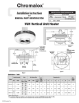
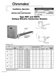
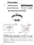
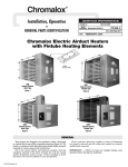
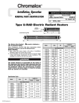
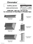
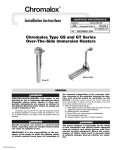
Chromalox
®
Installation, Operation
SERVICE REFERENCE
DIVISION
and
RENEWAL PARTS IDENTIFICATION
4
SALES
REFERENCE
SECTION
(Supersedes PF457-7)
CVEP
PF457-8
161-302639-001
DATE
JUNE, 2010
Type CVEP-C
Convection Air Heater for Hazardous Locations
NOTICE: Carefully remove heater from carton and check for
shipping damage. Any damage claims should be entered
immediately with the carrier.
GENERAL
Type CVEP Convection Heaters are designed for use in Class
I, Div I hazardous environments. Units without control options
are suitable for areas classified as Groups B, C & D. Units with
built-in controls can be supplied for groups C and D or B, C and
D. Refer to classification stamped on heater nameplate.
FIRE/EXPLOSION HAZARD. To prevent ignition of hazardous atmospheres, this heater should not be installed in
areas where vapors or gases having an ignition temperature less than 280˚C (536˚F)(T2A) at 1.8kW, 3.6kW, 4.5kW,
7.6kW, 9.0kW or 180˚C (356˚F)(T3A) at 1.6kW, 3.2kW,
4.0kW are present.
These heaters must not be operated in ambient temperatures exceeding 40˚C (104˚F).
1. Connect air heaters to the same line voltage as on heater nameplate.
2. Heaters can be mounted individually end to end.
3. Heaters can be mounted directly on any type of surface masonry,
concrete, block, plastered walls, metal framework, etc.-using
appropriate hardware.
4. All controls such as thermostat and contactor, when required must
have the same explosion-proof rating as heater.
5. Do not install one unit above the other.
6. Units are mounted a minimum of 8” above the floor.
7. Heaters are mounted on wall in a horizontal position with terminal end at right. Never recess heater into wall.
8. NOTE: Article 500 of the National Electric Code (NEC) outlines requirements for installation of electrical equipment in hazardous (Classified) locations.
9. All unit electrical installation fittings, conduit, wiring and seals
must meet NEC and local codes for hazardous locations. External
line fusing or circuit breaker protection is required.
10. Failure to understand and follow these installation instructions
and the “WARNING” notes contained therein may result in
severe personal injury, death or substantial property damage.
ELECTRIC SHOCK HAZARD. Any installation
involving electric heaters must be performed by a
qualified person and must be effectively grounded
in accordance with the National Electrical Code to
eliminate shock hazard.
INSTALLATION
ELECTRIC SHOCK HAZARD. Disconnect all power
before installing or servicing heater. Failure to do so
could result in personal injury or property damage.
Heater must be installed by a qualified person in accordance with the National Electrical Code, NFPA 70.
1. Remove front panel by removing screws.
2. Locate desired heater position on wall.
3. Locate mounting holes for rear panel. Rear panel must be a minimum of 8” from the floor.
4. Refer to Figure 1A, 1B or 1C for mounting hole layout for each
cabinet size.
© 2010 Chromalox, Inc.
5. Drill a pilot hole in wall mounting surface at each mounting hole
location. Use a convenient small size drill.
6. Drill the mounting holes in accordance with size in Table 1. Insert
anchors where applicable.
7. Fasten rear panel to wall with screws noted in Table 1.
8. Replace front panel and screws.
FIRE HAZARD. Never operate heater with front panel
off. Adequate air flow across heating elements
requires the front panel to be in place. The heating
elements could overheat causing equipment damage
or personal injury.
INSTALLATION
CVEP MODELS WITHOUT CONTROLS — GROUPS B, C AND D
Figure 1A
3/4" Conduit Entrance
Dimensions (In.)
7
B
C
D
D
C
See Detail "A"
19
8-15/16
20-1/16
3-3/8
2-3/8
5-1/16
A
kW
A
B
C
D
1.6
1.8
3.6
34
20
10
7
3.2
7.6
58
32
16
13
4.0
4.5
9.0
70
48
24
11
CVEP MODELS WITH BUILT-IN CONTROLS — GROUPS B, C AND D
Figure 1B
1" Conduit Entrance
Dimensions (In.)
8-7/8
B
D
C
D
C
8-15/16
See Detail "A"
kW
A
B
C
D
1.6
1.8
3.6
34
20
10
7
3.2
7.6
58
32
16
13
4.0
4.5
9.0
70
48
24
11
19 20-1/16
Feet are Optional
Primarily Used to Protect
Thermowell During Shipping
and Installation
A
CVEP MODELS WITH THERMOSTAT ONLY — GROUPS C AND D
Figure 1C
3/4" Conduit Entrance
Dimensions (In.)
7
D
C
C
D
8-15/16
See Detai "A"
19
20-1/16
3-3/8
2-3/8
5-1/16
A
kW
A
B
C
D
1.6
1.8
3.6
34
20
10
7
3.2
7.6
58
32
16
13
4.0
4.5
9.0
70
48
24
11
Table 1 — Suggested Heater Mounting Screws — Types and Sizes
Type of Mounting
Surface
Concrete Block
Masonry
** Accessory
Hardware
Screw Type
Drill Size and Type
Screw Size to Fit
Mtg Hole Size
Ackerman
Rd. Hd. Mach. Steel
1/2” Masonry
† 1/4” x 20 x.............lg
Lead Anchor
Rd. Hd. Mach Steel or Pan Hd.
Metal (Self Tapping)
5/16” Masonry
† # 1/4” x .................lg
Wood Studs
——
Wood or Metal (Self Tapping)
——
† # 1/4” x .................lg
Plaster wall Hollow or
Similar Type
——
Toggle Bolt
#7 Twist
† # 1/4” x .................lg
* Metal Beam,
Channel, etc.
Nuts
Washers
Rd. Hd. Mach. Steel
#7 Twist
† 1/4” x 20 x.............lg
5/16
7/8
1/2
*If clearance permits use washer, lockwasher and nut; otherwise drill and tap to these lengths add thickness of beam, washers, nut, etc.
**If mounting structure permits. Except plastered hollow walls explosive type anchors can be used. Suggested size noted in Table and/or
sketches be used to determine size of anchors.
†Select overall length of screw to provide a minimum penetration of 1 inch into base wall material.
2
Mounting Hole
Detail “A”
WIRING
4. Remove cover of conduit box for connections. Use either opening
and plug the other with the plug provided.
5. In single phase units the heaters must be wired in parallel, combining L1 to L1, L2 to L2 and for 3 phase unit, L3 to L3.
6. Re-assemble cover with a minimum of 7 turns.
ELECTRIC SHOCK HAZARD. Any installation
involving electric heaters must be performed by a
qualified person and must be effectively grounded
in accordance with the National Electrical Code to
eliminate shock hazard.
1. All wiring should be done in accordance with local codes and
the National Electrical Code by a qualified person as defined in
the NEC.
FIRE/EXPLOSION HAZARD.(Group B atmospheres)
To prevent ignition of Group B atmospheres, conduit
runs must not exceed 3/4” in size and all conduit
runs 1/2” size and larger must have a sealing fitting
connected within 2”, 6” or 18” of the terminal enclosure depending on the exact model. For correct
placement, refer to data located on the enclosure
label.
CAUTION: Use copper conductors only.
2. Rough-in-line-wiring to unit in manner approved for hazardous
locations. (See warning below.)
3. Wire per diagrams 1 through 6 based on the rating and control
options listed in table 2. Refer to table 3 for amperage specifications.
Single Phase — No Controls, Volts > 277V
& 120–277V When Heater Amps > 22A
Single Phase — No Controls, 120-277V
& Heater Amps < 22A
External
Contactor
Elements
Optional Thermostat
Built-In or Ext. Supplied
Control
Voltage
Optional Thermostat
Built-In or Ext. Supplied
Diagram 1
Elements
Diagram 2
Single or Three Phase
With Controls — Contactor & Transformer
Three Phase – No Controls
Contactor
External
Contactor
Element Wiring
1 PH or 3 PH
Single or Double
Element
Elements
Control
Voltage
Optional Thermostat
Built-In or Ext. Supplied
Diagram 3
Transformer
Diagram 4
Single or Three Phase With Controls —
Contactor & External Supplied Control Voltage
Single or Three Phase
With Controls — Contactor & Line Voltage Control
Contactor
Contactor
Element Wiring
1 PH or 3 PH
Single or Double
Element
Line
Voltage
Control
Voltage
Optional Thermostat
Built-In or Ext. Supplied
External
Supplied
Control
Voltage
Optional Thermostat
Built-In or Ext. Supplied
Diagram 5
Diagram 6
Terminal
Block
Element Wiring
1 PH or 3 PH
Single or Double
Element
Optional Thermostat
Built-In or Ext. Supplied
OPERATION
property damage, back-up controls are essential.
1. Do not operate heater at voltages in excess of that stamped on
the heater since excess voltage will shorten heater life and
cause high element temperatures which may exceed allowable
temperatures of operation in a hazardous atmosphere.
The system designer is responsible for the safety
of this equipment and should install adequate
back-up controls and safety devices with their
electric heating equipment. Where the consequences of failure could result in personal injury or
3
MAINTENANCE
1. Before activating for next heating season, vacuum or use compressed air to remove accumulated dust or lint, which otherwise
may restrict proper air flow.
2. Periodically check all electrical connections and retighten to avoid
electrical wiring difficulties.
3. Check to ensure terminal cover is tightly closed, before energizing.
ELECTRIC SHOCK HAZARD. Disconnect all power
before installing or servicing heater. Failure to do
so could result in personal injury or property damage. Heater must be installed by a qualified person in accordance with the National Electrical
Code, NFPA 70.
Sealed, Heavy duty Finned
Element assembly.
Explosion Proof
Junction Box
for Field wiring
Mounting Holes
ELEMENT REPLACEMENT
3. Remove front panel by removing screws.
4. Loosen aluminum coupling connecting element to junction box.
5. Remove screws and bracket holding element end opposite junction box.
6. Disconnect aluminum coupling connection element to junction
box.
7. Remove element from cabinet.
8. Install element in reverse sequence.
ELECTRIC SHOCK HAZARD. Disconnect all power
before installing or servicing heater. Failure to do
so could result in personal injury or property damage.
1. Disconnect power from circuit.
2. Remove cover from junction box and disconnect element wiring.
4
RENEWAL PARTS IDENTIFICATION
MANUFACTURER MODEL NUMBER BREAKDOWN (located on unit nameplate)
Model
CVEP
Explosion Proof Convection Heater
Temperature Rating
CVEP-C
Code
kW
ID Number
˚F
˚C
(BTU)
16
18
32
36
40
45
76
90
1.6
1.8
3.2
3.6
4.0
4.5
7.6
9.0
T3A
T2A
T3A
T2A
T3A
T2A
T2A
T2A
356
536
356
536
356
536
536
536
180
280
180
280
180
280
280
280
5,500
6,150
11,000
12,300
13,600
15,350
25,930
30,700
Code
Voltage
1
2
3
4
5
6
7
8
9
120
240
380
480
415
575
277
208
600
1.8
9.0
9.0
9.0
9.0
9.0
9.0
9.0
9.0
Code
Phase
Maximum kW Allowable
1
3
1Ø
3Ø (Not available in 120, 277V)
Control Combination
Code
Contactor
Coil
Transformer
Secondary
00
30
31
32
33
34
35
None
24 Volt
24 Volt
120 Volt
120 Volt
208/240 Volt
277 Volt
None
24 Volt
None
120 Volt
None
None
None
Code
00
40
42
CVEP-C
36
2
1
30
5
42
Temperature Control
None
Thermostat 40 - 90˚F
Group B, C & D
Thermostat Group C & D
50 - 90˚F
TABLE 2 — TEMPERATURE SPECIFICATIONS
DIMENSIONS
REPLACEMENTS
ELEMENTS REQUIREMENTS
Temperature Rating T3A 356˚F (180˚C)
Common To Units W & W/O Suffix B
kW
BTU
Volts
Phase
Amps
Model
Width A
Height B
Depth C
Wt. (Lbs.)
Element P/N
Qty.
1.6
1.6
1.6
1.6
1.6
1.6
1.6
1.6
5,500
5,500
5,500
5,500
5,500
5,500
5,500
5,500
208
208
240
240
277
480
480
575
1
3
1
3
1
1
3
3
7.7
4.4
6.7
3.8
5.8
3.3
1.9
1.6
CVEP-C-16-81
CVEP-C-16-83
CVEP-C-16-21
CVEP-C-16-23
CVEP-C-16-71
CVEP-C-16-41
CVEP-C-16-43
CVEP-C-16-63
34”
34”
34”
34”
34”
34”
34”
34”
20-1/16”
20-1/16”
20-1/16”
20-1/16”
20-1/16”
20-1/16”
20-1/16”
20-1/16”
8-15/16”
8-15/16”
8-15/16”
8-15/16”
8-15/16”
8-15/16”
8-15/16”
8-15/16”
58
58
58
58
58
58
58
58
003-304650-002
003-304650-005
003-304650-096
003-304650-006
003-304650-004
003-304650-091
003-304650-009
003-304650-010
2
2
2
2
2
2
2
2
3.2
3.2
3.2
3.2
3.2
3.2
3.2
3.2
11,000
11,000
11,000
11,000
11,000
11,000
11,000
11,000
208
208
240
240
277
480
480
575
1
3
1
3
1
1
3
3
15.4
8.9
13.3
7.7
11.6
6.7
3.8
3.2
CVEP-C-32-81
CVEP-C-32-83
CVEP-C-32-21
CVEP-C-32-23
CVEP-C-32-71
CVEP-C-32-41
CVEP-C-32-43
CVEP-C-32-63
58”
58”
58”
58”
58”
58”
58”
58”
20-1/16”
20-1/16”
20-1/16”
20-1/16”
20-1/16”
20-1/16”
20-1/16”
20-1/16”
8-15/16”
8-15/16”
8-15/16”
8-15/16”
8-15/16”
8-15/16”
8-15/16”
8-15/16”
94
94
94
94
94
94
94
94
003-304650-023
003-304650-026
003-304650-097
003-304650-027
003-304650-025
003-304650-093
003-304650-030
003-304650-031
2
2
2
2
2
2
2
2
4.0
4.0
4.0
4.0
4.0
4.0
4.0
4.0
13,600
13,600
13,600
13,600
13,600
13,600
13,600
13,600
208
208
240
240
277
480
480
575
1
3
1
3
1
1
3
3
19.2
11.1
16.7
9.6
14.4
8.3
4.8
7.0
CVEP-C-40-81
CVEP-C-40-83
CVEP-C-40-21
CVEP-C-40-23
CVEP-C-40-71
CVEP-C-40-41
CVEP-C-40-43
CVEP-C-40-63
70”
70”
70”
70”
70”
70”
70”
70”
20-1/16”
20-1/16”
20-1/16”
20-1/16”
20-1/16”
20-1/16”
20-1/16”
20-1/16”
8-15/16”
8-15/16”
8-15/16”
8-15/16”
8-15/16”
8-15/16”
8-15/16”
8-15/16”
112
112
112
112
112
112
112
112
003-304650-045
003-304650-048
003-304650-046
003-304650-049
003-304650-047
003-304650-094
003-304650-052
003-304650-053
2
2
2
2
2
2
2
2
Temperature Rating T2A 536˚F (280˚C)
kW
1.8/3.6
1.8/3.6
1.8/3.6
1.8/3.6
1.8/3.6
1.8/3.6
1.8/3.6
1.8/3.6
7.6
7.6
7.6
7.6
7.6
7.6
7.6
7.6
4.5/9.0
4.5/9.0
4.5/9.0
4.5/9.0
4.5/9.0
4.5/9.0
4.5/9.0
4.5/9.0
BTU
Volts
Phase
Amps
Model
Width A
Height B
Depth C
Wt. (Lbs.)
Element P/N
Qty.
6,150/12,300
6,150/12,300
6,150/12,300
6,150/12,300
6,150/12,300
6,150/12,300
6,150/12,300
6,150/12,300
208
208
240
240
277
480
480
575
1
3
1
3
1
1
3
3
8.7/17.3
5.0/10.0
7.5/15.0
4.3/8.7
6.5/13.0
3.8/7.5
2.2/4.3
1.8/3.6
CVEP-C-18/36-81
CVEP-C-18/36-83
CVEP-C-18/36-21
CVEP-C-18/36-23
CVEP-C-18/36-71
CVEP-C-18/36-41
CVEP-C-18/36-43
CVEP-C-18/36-63
34”
34”
34”
34”
34”
34”
34”
34”
20-1/16”
20-1/16”
20-1/16”
20-1/16”
20-1/16”
20-1/16”
20-1/16”
20-1/16”
8-15/16”
8-15/16”
8-15/16”
8-15/16”
8-15/16”
8-15/16”
8-15/16”
8-15/16
46/58
46/58
46/58
46/58
46/58
46/58
46/58
46/58
003-304650-034
003-304650-038
003-304650-098
003-304650-039
003-304650-036
003-304650-037
003-304650-042
003-304650-043
1 or 2
1 or 2
1 or 2
1 or 2
1 or 2
1 or 2
1 or 2
1 or 2
25,930
25,930
25,930
25,930
25,930
25,930
25,930
25,930
208
208
240
240
277
480
480
575
1
3
1
3
1
1
3
3
36.5
21.1
31.7
18.3
27.4
15.8
9.1
7.6
CVEP-C-76-81
CVEP-C-76-83
CVEP-C-76-21
CVEP-C-76-23
CVEP-C-76-71
CVEP-C-76-41
CVEP-C-76-43
CVEP-C-76-63
58”
58”
58”
58”
58”
58”
58”
58”
20-1/16”
20-1/16”
20-1/16”
20-1/16”
20-1/16”
20-1/16”
20-1/16”
20-1/16”
8-15/16”
8-15/16”
8-15/16”
8-15/16”
8-15/16”
8-15/16”
8-15/16”
8-15/16”
94
94
94
94
94
94
94
94
003-304650-055
003-304650-058
003-304650-099
003-304650-059
003-304650-057
003-304650-095
003-304650-062
003-304650-063
2
2
2
2
2
2
2
2
15,350/30,700
15,350/30,700
15,350/30,700
15,350/30,700
15,350/30,700
15,350/30,700
15,350/30,700
15,350/30,700
208
208
240
240
277
480
480
575
1
3
1
3
1
1
3
3
21.6/43.3
12.5/25.0
18.8/37.5
10.8/21.7
16.2/32.5
9.4/18.8
5.4/10.8
4.5/9.0
CVEP-C-45/90-81
CVEP-C-45/90-83
CVEP-C-45/90-21
CVEP-C-45/90-23
CVEP-C-45/90-71
CVEP-C-45/90-41
CVEP-C-45/90-43
CVEP-C-45/90-63
70”
70”
70”
70”
70”
70”
70”
70”
20-1/16”
20-1/16”
20-1/16”
20-1/16”
20-1/16”
20-1/16”
20-1/16”
20-1/16”
8-15/16”
8-15/16”
8-15/16”
8-15/16”
8-15/16”
8-15/16”
8-15/16”
8-15/16”
87/112
87/112
87/112
87/112
87/112
87/112
87/112
87/112
003-304650-065
003-304650-069
003-304650-100
003-304650-070
003-304650-067
003-304650-068
003-304650-073
003-304650-074
1 or 2
1 or 2
1 or 2
1 or 2
1 or 2
1 or 2
1 or 2
1 or 2
6
REPLACEMENT PARTS
Model
Any Voltage
Front
Cover Assembly
Rear
Cover Assembly
Right
Side Panel
Left
Side Panel
Element
Support Bracket
CVEP-C-16/18/36
207-304644-101
207-304644-001
207-304644-201
304-304644-301
027-304646-001
CVEP-C-32/76
207-304644-102
207-304644-002
207-304644-201
304-304644-301
027-304646-001
CVEP-C-40/45/90
207-304644-103
207-304644-003
207-304644-201
304-304644-301
027-304646-001
* Included when unit is equipped with control(s).
C V
E P
C
kW
Volts Phase
Control
Control Combination
Code
Contactor
Coil
Transformer
Secondary
00
30
31
32
33
34
35
None
24 Volt
24 Volt
120 Volt
120 Volt
208/240 Volt
277 Volt
None
24 Volt
None
120 Volt
None
None
None
Coil Voltage
24V
120V
208/240V
277V
Contactor
30 Amp
072-304551-001
072-304551-007
072-304551-013
072-304551-019
Stat
Code
00
40
42
50 Amp
072-304551-002
072-304551-008
072-304551-014
072-304551-020
7
Thermostat
None
300-049197-003
300-113075-003
Primary
Voltage
Secondary
Voltage
Transformer
208/240/480
208/240/480
277
575
277/575
24
120
24
24
120
315-304252-002
315-304252-001
315-304252-004
315-304252-005
315-304252-003
Limited Warranty:
Please refer to the Chromalox limited warranty applicable to this product at
http://www.chromalox.com/customer-service/policies/termsofsale.aspx.
2150 N. RULON WHITE BLVD., OGDEN, UT 84404
Phone: 1-800-368-2493
www.chromalox.com
02 - 074
TA - Q4 - EF
Litho in U.S.A.