1
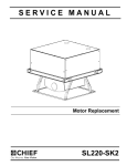
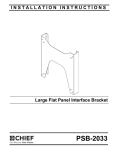
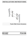
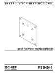
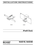
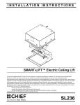
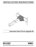
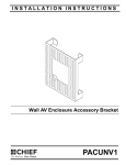
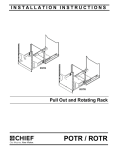
SERVICE MANUAL
Motor Replacement
Spanish Product Description
German Product Description
Portuguese Product Description
Italian Product Description
Dutch Product Description
French Product Description
SL236 Motor Replacement
SL236 Motor Replacement
Service Manual
DISCLAIMER
Milestone AV Technologies and its affiliated corporations and
subsidiaries (collectively "Milestone"), intend to make this
manual accurate and complete. However, Milestone makes no
claim that the information contained herein covers all details,
conditions or variations, nor does it provide for every possible
contingency in connection with the installation or use of this
product. The information contained in this document is subject
to change without notice or obligation of any kind. Milestone
makes no representation of warranty, expressed or implied,
regarding the information contained herein. Milestone assumes
no responsibility for accuracy, completeness or sufficiency of
the information contained in this document.
WARNING: Failure to read, thoroughly understand, and
follow all instructions can result in serious personal injury,
damage to equipment, or voiding of factory warranty! It is the
installer’s responsibility to make sure all components are
properly assembled and installed using the instructions
provided.
WARNING: Use this mounting system only for its intended
use as described in these instructions. Do not use
attachments not recommended by the manufacturer.
WARNING: Never operate this mounting system if it is
Chief® is a registered trademark of Milestone AV Technologies.
All rights reserved.
IMPORTANT SAFETY INSTRUCTIONS
damaged. Return the mounting system to a service center for
examination and repair.
WARNING: Do not use this product outdoors.
--SAVE THESE INSTRUCTIONS--
WARNING: A WARNING alerts you to the possibility of
serious injury or death if you do not follow the instructions.
CAUTION: A CAUTION alerts you to the possibility of
damage or destruction of equipment if you do not follow the
corresponding instructions.
TOOLS FOR INSTALLATION / PARTS
1/8"
(included)
B (2)*
[Coupler]
A (1)*
[Replacement
Motor]
C (4)
10-24
D (8)
.750 x .260 x .048
E (1)
1/8"
F (2)
1.0 x .25 x .437
G (4)
1/4-20
H (6)
8-32 x 5/16"
J (8)
1/4-20 x 3/8"
K (4)
1.0 x .640 x .080
L (6)
10-24 x 3/16"
*NOTE: The appearance of these parts may vary from the parts being removed during service due to Chief’s program
of continuous improvement.
2
Service Manual
SL236 Motor Replacement
REMOVING MOTOR
1.
Fully lower SL236, if possible.
2.
Turn off and remove power from SL236.
3.
Remove projector from SL236 following instructions
included with the SL236.
4.
Remove signal and power cables from projector.
5.
Remove projector cradle by removing four locking nuts (two
on each side) and additional washers and spacers. (See
Figure 1)
Remove plate
Remove
plate
6
x6
Figure 2
5
5
x4
Set Screws
6
Figure 1
6.
Remove six screws (three on each side) from plate and
remove plate for easier access to motor area.
(See
Figure 2)
7.
Restore power to SL236.
8.
Run the lift up or down until the set screws on the motor
couplers face outward so they can be removed in a later
step. (See Figure 3)
9.
Remove power from SL236.
Motor
Coupler
Figure 3
IMPORTANT ! : Do NOT remove set screws yet.
3
SL236 Motor Replacement
Service Manual
10. Attach wire or something of equivalent strength to the joist
mounting tabs on the SL236.
Motor Cover
11. Connect these wires to the front of hinge assembly. (See
Figure 4)
Wiring cover
IMPORTANT ! : Wires should be connected in minimum
of two places to prevent the hinge assembly from
dropping when the motor is removed.
Joist Mounting Tabs
9
x6
Figure 5
13. Remove four set screws from each of the two motor
couplers. (See Figure 6)
Figure 4
12. Remove motor cover and wiring cover by removing six
Phillips head machine screws. (See Figure 5)
NOTE: The wiring cover will only be present on newer units.
Older units will not have this cover.
10
Figure 6
4
x8
Service Manual
SL236 Motor Replacement
14. Slide motor couplers toward outside of the lift.(See Figure 7)
15. Remove the four nuts and four flat washers holding the
motor to the back plate of the lift. (See Figure 7)
3
16. Unplug and remove the motor.
(C) x 4
17. Slide both motor couplers toward the center of the lift and
remove couplers from the lift.
(D) x 4
2 (B)
2 (B)
x4
12
11
11
Motor coupler
Motor coupler
Rubber
Grommets
(A)
Figure 8
Motor
Figure 7
4.
Plug in motor.
5.
Slide motor couplers (B) towards motor (A) and fasten in
place using eight 1/4-20 x 3/8" set screws (J) (four on each
motor coupler). (See Figure 9)
REPLACING MOTOR
1.
(A)
Ensure that rubber grommets are attached properly to the
new motor (A).
NOTE: Use the old motor assembly as a reference for proper
placement of rubber grommets.
2.
Install two new motor couplers (B) and slide towards outside
of lift. (See Figure 8)
3.
Place replacement motor (A) in place and fasten with four
10-24 locknuts (C) and four .750 x .260 x .048 flat washers
(D) (See Figure 8)
IMPORTANT ! : Do NOT overtighten the locknuts! Stop
tightening when one to two threads protrude from the
locknut.
5
(J) x 8
(B) x 2
Figure 9
5
SL236 Motor Replacement
6.
Service Manual
Replace the motor cover and wiring cover (if present) and
fasten with six 8-32 x 5/16" Phillips head screws (H) . (See
Figure 10)
8.
Remove cable or wires attached to mounting tabs in Step
10 of Removing Motor section.
9.
Restore power to SL236.
10. Verify that SL236 is operating properly when moving up and
down.
6
11. Remove power from SL236.
(H) x 6
Motor cover
Figure 10
7.
Replace plate removed in Step 5 of Removing Motor
section and fasten with six 10-24 x 3/16" Phillips head
screws (L). (See Figure 11)
NOTE: Install middle screw on each side first and set plate on
top of two middle screws before adding additional four
screws.
7
(L) x 6
Install middle
screw first
Figure 11
6
Service Manual
SL236 Motor Replacement
12. Reinstall projector cradle to SL236 lift. (See Figure 12)
•
Use two nylon spacers (K), two flat washers
(D) and two locknuts (G) for rear lift arms.
•
Use two steel spacers (F), two nylon spacers
(K), two flat washers (D) and two locknuts (G)
for front lift arms.
13. Reinstall the projector into the SL236 following instructions
included with the SL236.
14. Re-route projector power and signal cables following
instructions in the SL236 installation instructions.
15. Restore power to SL236.
(F) x 2
(D) x 2
(G) x 2
(K) x 2
(D) x 2
(K) x 2
(G) x 2
Figure 12
7
SL236 Motor Replacement
Service Manual
USA/International
Europe
Chief Manufacturing, a products division
of Milestone AV Technologies
8800-002219 Rev00
2012 Milestone AV Technologies, a
Duchossois Group Company
www.chiefmfg.com
09/12
Asia Pacific
A
P
F
A
P
F
A
6436 City West Parkway, Eden Prairie, MN 55344
800.582.6480 / 952.225.6000
877.894.6918 / 952.894.6918
Franklinstraat 14, 6003 DK Weert, Netherlands
+31 (0) 495 580 852
+31 (0) 495 580 845
Office No. 1 on 12/F, Shatin Galleria
18-24 Shan Mei Street
Fotan, Shatin, Hong Kong
P 852 2145 4099
F 852 2145 4477