1
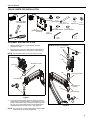
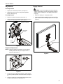
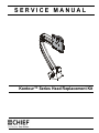
SERVICE MANUAL
Kontour™ Series Head Replacement Kit
Spanish Product Description
German Product Description
Portuguese Product Description
Italian Product Description
Dutch Product Description
French Product Description
Service Manual
Milestone AV Technologies and its affiliated corporations and
subsidiaries (collectively “Milestone”), intend to make this
manual accurate and complete. However, Milestone makes no
claim that the information contained herein covers all details,
conditions or variations, nor does it provide for every possible
contingency in connection with the installation or use of this
product. The information contained in this document is subject
to change without notice or obligation of any kind. Milestone
makes no representation of warranty, expressed or implied,
regarding the information contained herein. Milestone assumes
no responsibility for accuracy, completeness or sufficiency of
the information contained in this document.
Chief® and Kontour™ are registered trademarks of Milestone
AV Technologies. All rights reserved.
IMPORTANT SAFETY INSTRUCTIONS!
damage to equipment, or voiding of factory warranty! It is the
installer’s responsibility to make sure all components are
properly assembled and installed using the instructions
provided.
WARNING: Exceeding the weight capacity can result in
serious personal injury or damage to equipment! It is the
installer’s responsibility to make sure the combined weight of
all components located attached to the replacement tilt head
accessory up to (and including) the display does not exceed
the weight limit listed for the mount to which it is attached.
Use with products heavier than the maximum weight
indicated may result in collapse of the mount and its
accessories causing possible injury.
WARNING: Use this mounting system only for its intended
use as described in these instructions. Do not use
attachments not recommended by the manufacturer.
WARNING: A WARNING alerts you to the possibility of
serious injury or death if you do not follow the instructions.
WARNING: Never operate this mounting system if it is
CAUTION: A CAUTION alerts you to the possibility of
damaged. Return the mounting system to a service center for
examination and repair.
damage or destruction of equipment if you do not follow the
corresponding instructions.
WARNING: Do not use this product outdoors.
--SAVE THESE INSTRUCTIONS--
WARNING: Failure to read, thoroughly understand, and
follow all instructions can result in serious personal injury,
DIMENSIONS
1.83
46.4
INTERFACE
ROTATION
RANGE
90
TILT RANGE
75 UP
10 DOWN
MOUNTING PATTERN
COMPATIBILITY
100 X 100
75 X 75
2
Service Manual
TOOLS / PARTS FOR INSTALLATION
B (1)
C (1)
[Socket bit]
[Thick spacer]
3/16” (included)
1/8” (included)
A (1)
[Replacement head
accessory]
3/4"
D (1)
5/16-18 x 2 3/4"
H (2)
[Thin steel washer]
E (1)
F (1)
#10-24 x 1/4”
5/16-18”
J (1)
[Plastic washer]
G (1)
[Pivot pin]
L (1)
1/8”
K (1)
3/16”
#2
ASSEMBLY AND INSTALLATION
1.
Remove display from K1 head assembly. Set aside
hardware for reuse.
2.
Remove button head cap screw, spacers and washers to
disassemble head from K1 mounting arm. (See Figure 1)
NOTE: Set aside decorative ring and pivot ring for reuse.
(K1W120 shown as example)
(H) x 2
(D)
3
(C)
(K1W120 shown
as example)
(A)
(J)
set aside for reuse
pivot ring
(G)
pivot ring (reused)
decorative ring
2
decorative ring
(reused)
(F)
(K1W120 arm)
Figure 1
3
3.
Use 5/16-18 x 2 3/4" button head cap screw (D), two thin
steel washers (H), plastic washer (J), thick spacer (C), pivot
pin (G), removed pivot ring, removed decorative ring, 5/1618” lock nut (F) and socket bit (B) to secure replacement
head assembly (A) to Kontour mount. (See Figure 2)
(B)
Figure 2
NOTE: Use 3/4" wrench to hold socket bit (B) in position while
button head cap screw (D) is tightened.
3
Service Manual
Display Installation
For recessed mounting hole installation:
1.
•
Remove quick release faceplate from mount by pulling
quick release lever and sliding faceplate off mount. (See
Figure 3)
•
1
Place four spacers on top of mounting holes on
back of display. (See Figure 5)
Using Phillips screwdriver, carefully install four
M4x25mm screws through corresponding holes
on faceplate, spacers and into the mounting holes
on the display. (See Figure 5)
(for recessed mounting holes)
(A)
quick release
faceplate
3
M4x25mm
x4
(spacers) x 4
1
quick release lever
Figure 3
2.
Carefully place display face down on protective surface.
NOTE: Use display mounting hardware included with K1
Series mount to attach display to new faceplate.
3.
Connect faceplate to display
For flush mounting hole installation:
•
Using Phillips screwdriver, carefully install four
M4x14mm screws through corresponding holes
on faceplate and into the mounting holes on the
display. (See Figure 4)
Figure 5
(for flush mounting holes)
quick release
faceplate
3
4.
Position display with faceplate attached above mount. (See
Figure 6)
5.
Slide faceplate onto mounting head until quick release tab
clicks into place. (See Figure 6)
M4x14mm
x4
5
Figure 4
4
Figure 6
Service Manual
Adjustments
Display Removal
Pitch Adjustment
1.
Adjust pitch to desired tilt position. (See Figure 7)
2.
Adjust pitch tension screw to change the adjustment
tension. (See Figure 7)
WARNING: Only remove display from mount when the
display can be lifted up from the mount! DO NOT remove
display unless the display is in the upright position! (See
Figure 9)
Pivot Adjustment
1.
Make sure display is in the upright position.
3.
Adjust pivot position as desired. (See Figure 7)
2.
4.
Use 3/16” hex key (K) to adjust pivot point tension screws to
change pivot adjustment tension. (See Figure 7)
Remove quick release faceplate from mount by pulling
quick release lever and sliding faceplate off mount. (See
Figure 9)
Rotational tension
5
3
pivot point
tension
1
2
pitch
tension
quick release tab
Figure 7
Rotational Adjustment
NOTE: (Optional) Rotational adjustment may be locked by
installing rotational locking screw (E) into back of
faceplate. (See Figure 8)
Figure 9
(E)
Figure 8
5.
The monitor may be adjusted 90 degrees in either direction
in order to provide a portrait view of the monitor. (See Figure
7)
6.
Use 3/16” hex key (K) to adjust rotational adjustment screw
to adjust rotational tension. (See Figure 7)
5
Service Manual
6
Service Manual
7
Service Manual
USA/International
Europe
Chief, a products division of
Milestone AV Technologies
8800-002743 Rev00
2015 Milestone AV Technologies
www.chiefmfg.com
05/15
Asia Pacific
A
P
F
A
P
F
A
6436 City West Parkway, Eden Prairie, MN 55344
800.582.6480 / 952.225.6000
877.894.6918 / 952.894.6918
Franklinstraat 14, 6003 DK Weert, Netherlands
+31 (0) 495 580 852
+31 (0) 495 580 845
Office No. 918 on 9/F, Shatin Galleria
18-24 Shan Mei Street
Fotan, Shatin, Hong Kong
P 852 2145 4099
F 852 2145 4477