1
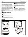
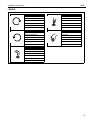
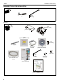
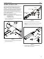
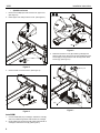
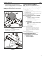
INSTALLATION INSTRUCTIONS
Interactive Short-Throw Upgrade Kit
Spanish Product Description
German Product Description
Portuguese Product Description
Italian Product Description
Dutch Product Description
French Product Description
WM2I
WM2I
Installation Instructions
DISCLAIMER
Milestone AV Technologies and its affiliated corporations and
subsidiaries (collectively "Milestone"), intend to make this
manual accurate and complete. However, Milestone makes no
claim that the information contained herein covers all details,
conditions or variations, nor does it provide for every possible
contingency in connection with the installation or use of this
product. The information contained in this document is subject
to change without notice or obligation of any kind. Milestone
makes no representation of warranty, expressed or implied,
regarding the information contained herein. Milestone assumes
no responsibility for accuracy, completeness or sufficiency of
the information contained in this document.
Chief® is a registered trademark of Milestone AV Technologies.
All rights reserved.
WARNING: Failure to read, thoroughly understand, and
follow all instructions can result in serious personal injury,
damage to equipment, or voiding of factory warranty! It is the
installer’s responsibility to make sure all components are
properly assembled and installed using the instructions
provided.
WARNING: Failure to provide adequate structural strength
for this component can result in serious personal injury or
damage to equipment! It is the installer’s responsibility to
make sure the structure to which this component is attached
can support five times the combined weight of all equipment.
Reinforce the structure as required before installing the
component.
IMPORTANT WARNINGS AND
CAUTIONS!
WARNING: A WARNING alerts you to the possibility of
serious injury or death if you do not follow the instructions.
CAUTION: A CAUTION alerts you to the possibility of
damage or destruction of equipment if you do not follow the
corresponding instructions.
DIMENSIONS
DIMENSIONS: [MILLIMETERS]
INCHES
2
Installation Instructions
WM2I
LEGEND
Tighten Fastener
Phillips Screwdriver
Apretar elemento de fijación
Destornillador Phillips
Befestigungsteil festziehen
Kreuzschlitzschraubendreher
Apertar fixador
Chave de fendas Phillips
Serrare il fissaggio
Cacciavite a stella
Bevestiging vastdraaien
Kruiskopschroevendraaier
Serrez les fixations
Tournevis à pointe cruciforme
Loosen Fastener
By Hand
Aflojar elemento de fijación
A mano
Befestigungsteil lösen
Von Hand
Desapertar fixador
Com a mão
Allentare il fissaggio
A mano
Bevestiging losdraaien
Met de hand
Desserrez les fixations
À la main
Security Wrench
Llave de seguridad
Sicherheitsschlüssel
Chave de segurança
Chiave di sicurezza
Veiligheidssleutel
Clé de sécurité
3
WM2I
Installation Instructions
REQUIRED TOOLS FOR INSTALLATION
5/32"
(security)
#2
PARTS
B (1)
[Interactive cover]
A (1)
[Cover - top]
D (4)
[Stylus replacement tips]
G (1)
[AAA battery]
C (1)
[Stylus]
E (1)
[Stylus wrist
strap kit]
K (1)
5/32"
(security)
H (1)
[Interactive USB cable
-15 ft.]
F (1)
[Interactive software]
M (4)
8-32 x 3/8"
L (4)
8-32 x 3/8"
(security)
J (1)
[Quick start guide]
N (1)
[Interactive software guide]
4
Installation Instructions
WM2I
ASSEMBLY AND INSTALLATION
The WM2I is designed to replace the existing cover(s) on the
WM210, WM220, WM230 and WM240, and to convert the
existing short throw mount to a Chief Interactive Mount
(WM2XXSI). The WM2XXSI works with standard projectors
and Windows® and Macintosh® computers. The Interactive
Mount will transform existing whiteboards or other hard, flat
surfaces, into interactive whiteboards and allows users to
present, annotate, and interact with their projected content and
all of their desktop applications.
Bracket
Mount cover
Inner telescoping
extrusion
4
Remove Existing Mount Cover(s)
x2
2
NOTE: Proceed to appropriate section - Single Mount Cover
or Split Mount Covers.
•
1.
Single Mount Cover
3
2
Remove two Phillips pan head screws to release existing
mount cover. (See Figure 1)
Figure 2
1
x2
3.
Remove inner telescoping extrusion. (See Figure 2)
4.
Slide mount cover away from wall mount and remove. (See
Figure 2)
5.
Reinstall inner telescoping extrusion. (See Figure 3)
5
Bracket
6
Figure 1
2.
x2
6
Remove two hex bolts and bracket from the underside of
the mount. (See Figure 2)
Figure 3
6.
Reinstall bracket and fasten with two hex head bolts
removed in Step 2. (See Figure 3)
5
WM2I
•
1.
2.
Installation Instructions
Split Mount Covers
Remove two Phillips pan head screws from upper cover.
(See Figure 4)
Raise upper cover away from the mount. (See Figure 4)
1
2
Route cables
2
Cartridge
Cartridge
(B)
Figure 6
3.
1
x2
Raise the interactive cover (B) containing cartridge and
attach to wall mount using two 8-32 x 3/8" Phillips pan head
screws (M) [or using two 8-32 x 3/8" security button head
screws (L)]. (See Figure 7)
Figure 4
3.
3
Remove lower cover from mount. (See Figure 5)
3
3
(B)
Figure 5
Install WMI
1.
Connect USB cable (H) to cartridge in interactive cover (B),
and route cable through strain relief channel on cartridge.
2.
Route cables from projector through strain relief channel on
cartridge in interactive cover (B). (See Figure 6)
6
(M or L) x 2
Figure 7
Installation Instructions
4.
WM2I
Lower the upper cover (A) onto the wall mount and
interactive cover (B), and fasten with two 8-32 x 3/8" Phillips
pan head screws (M) [or use two 8-32 x 3/8" security button
head screws (L)]. (See Figure 8)
NOTE: Be sure cables and cords are not pinched between
upper and lower covers.
Connecting Chief Interactive Mount
NOTE: Follow instructions in the Quick Start Guide (J).
IMPORTANT ! : After adding batteries to the stylus (C),
tighten the cap only to the point of being fingertip-tight.
Overtightening cap may cause the stylus to stop
transmitting signals.
1.
Connect projector to computer
2.
Connect USB cord (H) from cartridge in interactive cover (B)
to computer USB port.
3.
Insert interactive software CD (F) into computer, and follow
start-up and operating instructions.
(A)
Minimum System Requirements for WM2XXSI
•
Windows® System
Compatible PC with Pentium™ II 400 MHz+
processor and 256 MB RAM
•
Windows 2000, XP, Server 2003, Vista, or 7
•
30 MB available hard drive space
•
Available USB port
Macintosh® System
•
Power PC®/Intel™ 1.42 GHz+ processor and 1G
RAM
•
Mac OS X 10.5 through 10.6
•
25 MB available hard drive space
•
Available USB port
•
4
•
4
(M or L) x 2
Active Capture Area Size
Figure 8
5.
Exit cables out bottom of cover and through cable
management clips. (See Figure 9)
•
•
The maximum active capture area supported is:
4 ft x 7 ft or up to 94 inches diagonal measure.
The minimum active capture area supported is:
1.7 ft x 1.1 ft.
Connection Requirement
•
The interactive mount includes a USB cable.
Screen Recording Requirements
(Currently available only on Windows platform.)
•
•
Pentium™ IV processor
1.4GHz, with 512MB RAM
Cables
Cable management clips
(bottom view of mount)
Figure 9
7
Installation Instructions
WM2I
Environmental Interference Guide
Ultrasound Reflections
General proximity guideline: A distance of 12 feet
(approximately 4 meters) between the motion sensor and the
eBeam receiver will normally allow good performance with the
maximum board size. (See Figure 10)
Interference can be reduced by reducing the size of the
projection area.
Motion sensor OK
Motion Sensor Free Zone
12 feet
Motion sensor
Drawing surface
Figure 10
8
Installation Instructions
WM2I
WM2XXSI Placement and Projection Area
Constraints (See Figure 11)
•
•
•
•
There should be a minimum distance of 12 inches
between the base of the dual mount and the top of the
projection image.
The distance between the base of the dual mount and
the bottom corner of the projection image (both right
and left) should be less than or equal to 110 inches.
The projection image should start a minimum of 1 inch
from the base of the top frame of the whiteboard.
The projection image should be positioned within the
fan area extending from the Chief Interactive Dual
Mount. This fan area should not exceed 140 degrees.
Whiteboard Constraints
•
•
The whiteboard should not be thicker than 1". (See
Figure 11)
The ledge of the whiteboard frame should be less than
or equal to 1/3". (See Figure 11)
Important Notes
•
•
Do not put sticky notes, hanging paper, cables, outlets,
or other items below the wall mount or inside the
capture area. (See Figure 11)
Image should be placed one inch below the edge of the
whiteboard to minimize interference from the frame top.
<1/3"
>1"
Minimum 12 inches
from base of mount
to projection
Whiteboard
ledge
140°
Capture area
Projected areas
Projection
10
<1
i
h
nc
<1
10
es
in
ch
es
<1"
(Whiteboard side view)
Figure 11
9
WM2I
10
Installation Instructions
Installation Instructions
WM2I
11
WM2I
Installation Instructions
USA/International
Europe
Chief Manufacturing, a products division
of Milestone AV Technologies
8800-002063 Rev02
2011 Milestone AV Technologies, a
Duchossois Group Company
www.chiefmfg.com
12/11
Asia Pacific
A
P
F
A
P
F
A
8401 Eagle Creek Parkway, Savage, MN 55378
800.582.6480 / 952.894.6280
877.894.6918 / 952.894.6918
Franklinstraat 14, 6003 DK Weert, Netherlands
+31 (0) 495 580 852
+31 (0) 495 580 845
Office No. 1 on 12/F, Shatin Galleria
18-24 Shan Mei Street
Fotan, Shatin, Hong Kong
P 852 2145 4099
F 852 2145 4477