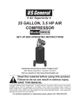
1
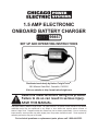
1.5 Amp Electronic
Onboard Battery Charger
99857
Set up and Operating Instructions
Distributed exclusively by Harbor Freight Tools®.
3491 Mission Oaks Blvd., Camarillo, CA 93011
Visit our website at: http://www.harborfreight.com
Read this material before using this product.
Failure to do so can result in serious injury.
Save this manual.
Copyright© 2008 by Harbor Freight Tools®. All rights reserved. No portion of this manual or any artwork
contained herein may be reproduced in any shape or form without the express written consent of
Harbor Freight Tools. Diagrams within this manual may not be drawn proportionally. Due to continuing
improvements, actual product may differ slightly from the product described herein. Tools required for
assembly and service may not be included.
For technical questions or replacement parts, please call 1-800-444-3353.
Save This Manual
Keep this manual for the safety warnings and precautions, assembly, operating, inspection, maintenance and cleaning
procedures. Write the product’s serial
number in the back of the manual near the
assembly diagram (or month and year of
purchase if product has no number). Keep
this manual and the receipt in a safe and
dry place for future reference.
NOTICE is used to
address practices
not related to personal injury.
CAUTION, without
the safety alert
symbol, is used to address
practices not related to
personal injury.
General Battery Charger Safety
Warnings
Important SAFETY
Information
WARNING Read all safety
warnings and instructions.
Failure to follow the warnings and
instructions may result in electric
shock, fire and/or serious injury.
Save all warnings and
instructions for future reference.
The term ″Battery Charger″ in the
warnings refers to your mainsoperated (corded) Battery Charger.
In this manual, on the labeling,
and all other information provided with this product:
This is the safety alert
symbol. It is used to alert
you to potential personal
injury hazards. Obey all
safety messages that
follow this symbol to avoid
possible injury or death.
1.
a.Keep work area clean and well lit.
Cluttered or dark areas invite accidents.
DANGER indicates
a hazardous
situation which, if not
avoided, will result in death or
serious injury.
b.Do not operate Battery Chargers in
explosive atmospheres, such as in
the presence of flammable liquids,
gases or dust. Battery Chargers
create sparks which may ignite the
dust or fumes.
WARNING
indicates a
hazardous situation which, if
not avoided, could result in
death or serious injury.
CAUTION, used
with the safety
alert symbol, indicates a
hazardous situation which, if
not avoided, could result in
minor or moderate injury.
SKU 99857
Work area safety
c.Keep children and bystanders
away while operating a Battery
Charger. Distractions can cause you
to lose control.
2.
Electrical safety
a.Battery Charger plug must match
the outlet. Never modify the plug
in any way. Do not use any adapter plugs with grounded Battery
Chargers. Unmodified plugs and
For technical questions, please call 1-800-444-3353.
Page 2
matching outlets will reduce risk of
electric shock.
non-skid safety shoes, hard hat, or
hearing protection used for appropriate conditions will reduce personal
injuries.
b.Avoid body contact with grounded
surfaces such as pipes, radiators,
ranges and refrigerators. There is
an increased risk of electric shock if
your body is grounded.
c.Do not overreach. Keep proper
footing and balance at all times.
This enables better control of the
Battery Charger in unexpected situations.
c.Do not expose Battery Chargers to
rain or wet conditions. Water entering a Battery Charger will increase
the risk of electric shock.
d.Dress properly. Do not wear loose
clothing or jewelry. Keep your
hair, clothing and gloves away
from moving parts. Loose clothes,
jewelry or long hair can be caught in
moving parts.
d.Do not abuse the cord. Never
use the cord for carrying, pulling
or unplugging the Battery Charger. Keep cord away from heat,
oil, sharp edges or moving parts.
Damaged or entangled cords increase the risk of electric shock.
e.Only use safety equipment that
has been approved by an appropriate standards agency. Unapproved
safety equipment may not provide
adequate protection. Eye protection
must be ANSI-approved and breathing protection must be NIOSH-approved for the specific hazards in the
work area.
e.When operating a Battery Charger
outdoors, use an extension cord
suitable for outdoor use. Use of a
cord suitable for outdoor use reduces
the risk of electric shock.
f. If operating a Battery Charger in a
damp location is unavoidable, use
a Ground Fault Circuit Interrupter
(GFCI) protected supply. Use of
a GFCI reduces the risk of electric
shock.
3.
Personal safety
a.Stay alert, watch what you are doing and use common sense when
operating a Battery Charger. Do
not use a Battery Charger while
you are tired or under the influence
of drugs, alcohol or medication. A
moment of inattention while operating
Battery Chargers may result in serious personal injury.
b.Use personal protective equipment. Always wear eye protection.
Safety equipment such as dust mask,
SKU 99857
4.
Battery Charger use and care
a.Do not force the Battery Charger.
Use the correct Battery Charger
for your application. The correct
Battery Charger will do the job better
and safer at the rate for which it was
designed.
b.Disconnect the plug from the power source from the Battery Charger
before making any adjustments,
changing accessories, or storing
Battery Chargers. Such preventive
safety measures reduce the risk of
starting the Battery Charger accidentally.
c.Store idle Battery Chargers out of
the reach of children and do not
allow persons unfamiliar with the
For technical questions, please call 1-800-444-3353.
Page 3
Battery Charger or these instructions to operate the Battery Charger. Battery Chargers are dangerous
in the hands of untrained users.
d.Maintain Battery Chargers. Check
for breakage of parts and any
other condition that may affect the
Battery Charger’s operation. If
damaged, have the Battery Charger repaired before use. Many accidents are caused by poorly maintained Battery Chargers.
e.Use the Battery Charger in accordance with these instructions,
taking into account the working
conditions and the work to be performed. Use of the Battery Charger
for operations different from those
intended could result in a hazardous
situation.
5.
Battery Charger Safety Warnings
1.
Maintain labels and nameplates on
the tool. These carry important safety
information. If unreadable or missing, contact Harbor Freight Tools for a
replacement.
2.
Avoid contact with battery acid. If
splashed, unplug Battery Charger
and immediately wash effected area
with clean water.
3.
Turn vehicle OFF and allow to cool
before plugging in Battery Charger.
Remove keys from vehicle ignition
before plugging in Battery Charger.
4.
Before operation, check to be sure
Battery Charger cables are connected to the correct battery posts. Red
must be connected to the Positive (+)
terminal. Black cable must be connected to the Negative (-) terminal.
5.
Keep Output Wires (12) and Power
Cable (8) clear of fan, fan belt, pulleys and any other moving parts of
the engine.
6.
Only use Battery Charger in a well
ventilated area to prevent build up of
explosive gasses.
7.
Do not allow the Red and Black terminals of the Battery Charger or the
vehicle battery cables to touch. Do
not allow the Red cables to touch the
frame or any metal part of the vehicle. Contact can cause an electrical
short resulting in sparks, burn injury
or damage to property.
8.
Only use in 12 VDC systems. Do not
use in any other voltage system.
Battery use and care
a.When battery is not in use, keep
away other metal objects, like
paper clips, coins, keys, nails,
screws or other small metal objects, that can make a connection from one terminal to another.
Shorting the battery terminals together may cause burns or a fire.
b.Under abusive conditions, liquid
may be ejected from the battery;
avoid contact. If contact accidentally occurs, flush with water. If
liquid contacts eyes, additionally
seek medical help. Liquid ejected
from the battery may cause irritation
or burns.
6.
parts. This will ensure that the safety
of the Battery Charger is maintained.
Service
a.Have your Battery Charger serviced by a qualified repair person
using only identical replacement
SKU 99857
For technical questions, please call 1-800-444-3353.
Page 4
9.
Do not attempt to start or jump a
vehicle with this Battery Charger
plugged in. Do not use this Battery
Charger to charge a dead, damaged
or severely discharged battery. This
charger is designed to “top off” and
maintain a battery at or near 12 VDC.
10. Do not leave the Charger unattended
when it is plugged into an electrical
outlet. Unplug the Charger from its
electrical outlet before leaving.
11.
The battery charger may
get hot during use. The
charger’s heat can build
up to unsafe levels and
create a fire hazard if it does not
receive adequate ventilation, due to
an electrical fault, or if it is used in a
hot environment.
Do not place the charger on a flammable surface. Do not obstruct any
vents on the charger. Especially
avoid placing the charger on carpets and rugs; they are not only
flammable, but they also obstruct
vents under the charger.
12. This product is not a toy. Keep it out
of reach of children.
13. People with pacemakers should
consult their physician(s) before use.
Electromagnetic fields in close proximity to heart pacemaker could cause
pacemaker interference or pacemaker failure. In addition, people with
pacemakers should:
• Avoid operating alone.
• Do not use with power switch locked
on.
• Properly maintain and inspect to
avoid electrical shock.
• Any power cord must be properly
grounded. Ground Fault Circuit InterSKU 99857
rupter (GFCI) should also be implemented – it prevents sustained electrical shock.
14. WARNING: Handling the cord on
this product will expose you to lead,
a chemical known to the State of
California to cause cancer, and birth
defects or other reproductive harm.
Wash hands after handling. (California Health & Safety Code § 25249.5,
et seq.)
15. WARNING: The brass components
of this product contain lead, a chemical known to the State of California
to cause birth defects (or other reproductive harm). (California Health &
Safety code 25249.5, et seq.)
16. The warnings, precautions, and instructions discussed in this instruction
manual cannot cover all possible conditions and situations that may occur.
It must be understood by the operator
that common sense and caution are
factors which cannot be built into this
product, but must be supplied by the
operator.
Save these
instructions.
For technical questions, please call 1-800-444-3353.
Page 5
Grounding
To prevent
electric shock
and death from
incorrect grounding
wire connection:
Check with a qualified
electrician if you are in doubt
as to whether the outlet is
properly grounded. Do not
modify the power cord plug
provided with the tool. Never
remove the grounding prong
from the plug. Do not use the
tool if the power cord or plug
is damaged. If damaged, have
it repaired by a service facility
before use. If the plug will not
fit the outlet, have a proper
outlet installed by a qualified
electrician.
of electric shock. (See 3-Prong Plug
and Outlet.)
2.
The grounding prong in the plug is
connected through the green wire inside the cord to the grounding system
in the tool. The green wire in the cord
must be the only wire connected to
the tool’s grounding system and must
never be attached to an electrically
“live” terminal. (See 3-Prong Plug
and Outlet.)
3.
The tool must be plugged into an
appropriate outlet, properly installed
and grounded in accordance with all
codes and ordinances. The plug and
outlet should look like those in the
preceding illustration. (See 3-Prong
Plug and Outlet.)
Double Insulated Tools: Tools
with Two Prong Plugs
Grounded Tools: Tools with Three
Prong Plugs
1.
1.
Tools marked with “Grounding Required” have a three wire cord and
three prong grounding plug. The
plug must be connected to a properly
grounded outlet. If the tool should
electrically malfunction or break
down, grounding provides a low
resistance path to carry electricity
away from the user, reducing the risk
SKU 99857
Tools marked “Double Insulated” do
not require grounding. They have
a special double insulation system
which satisfies OSHA requirements
and complies with the applicable
standards of Underwriters Laboratories, Inc., the Canadian Standard
Association, and the National Electrical Code. (See Outlets for 2-Prong
Plug.)
For technical questions, please call 1-800-444-3353.
Page 6
3.
4.
5.
6.
7.
As the distance from the supply outlet
increases, you must use a heavier
gauge extension cord. Using extension cords with inadequately sized
wire causes a serious drop in voltage,
resulting in loss of power and possible tool damage.
(See Table A.)
The smaller the gauge number of the
wire, the greater the capacity of the
cord. For example, a 14 gauge cord
can carry a higher current than a 16
gauge cord. (See Table A.)
RECOMMENDED MINIMUM WIRE
GAUGE FOR EXTENSION CORDS*
(120/240 VOLT)
NAMEPLATE
AMPERES
(at full load)
0 – 2.0
18
18
18
18
16
2.1 – 3.4
18
18
18
16
14
3.5 – 5.0
18
18
16
14
12
5.1 – 7.0
18
16
14
12
12
7.1 – 12.0
18
14
12
10
-
12.1 – 16.0
14
12
10
-
-
16.1 – 20.0
12
10
-
-
-
TABLE A
* Based on limiting the line
voltage drop to five volts at
150% of the rated amperes.
Symbology
When using more than one extension cord to make up the total length,
make sure each cord contains at
least the minimum wire size required.
(See Table A.)
If you are using one extension cord
for more than one tool, add the
nameplate amperes and use the sum
to determine the required minimum
cord size. (See Table A.)
If you are using an extension cord
outdoors, make sure it is marked with
the suffix “W-A” (“W” in Canada) to
indicate it is acceptable for outdoor
use.
EXTENSION CORD
LENGTH
150’
2.
Grounded tools require a three wire
extension cord. Double Insulated
tools can use either a two or three
wire extension cord.
Protect the extension cords from
sharp objects, excessive heat, and
damp or wet areas.
100’
1.
8.
75’
Extension Cords
dition. Always replace a damaged
extension cord or have it repaired by
a qualified electrician before using it.
50’
Double insulated tools may be used
in either of the 120 volt outlets shown
in the preceding illustration. (See
Outlets for 2-Prong Plug.)
25’
2.
Double Insulated
Canadian Standards Association
Underwriters Laboratories, Inc.
V~
A
Volts Alternating Current
Amperes
No Load Revolutions per Minute
n0 xxxx/min. (RPM)
Make sure the extension cord is properly wired and in good electrical con-
SKU 99857
For technical questions, please call 1-800-444-3353.
Page 7
Specifications
Electrical Requirements
120 V~ / 60 Hz
Output Voltage
12 VDC / 1.5 Amps
Charging Method
3-Stage trickle charge
Status Indicators
Overload Protection
Additional Protection
Red, Yellow and
Green LED lights
On / Off trickle
charging with Thermal
Overload Protection
Short Circuit and
Polarity Protection
Unpacking
When unpacking, check to make sure
that the item is intact and undamaged. If
any parts are missing or broken, please
call Harbor Freight Tools at the number
shown on the cover of this manual as soon
as possible.
Note: For additional information regarding
the parts listed in the following pages,
refer to the Assembly Diagram near
the end of this manual.
Mounting
1.
The Battery Charger must be mounted near the battery in the engine
compartment of the vehicle.
2.
Leave at least 2-½” clearance in front
of the Output Wires (12) Plug.
3.
You can mount the Charger on the
vehicle engine compartment wall
near the battery, or you can mount it
on a bracket held in place by the battery.
Bracket B (6)
Instructions for
putting into use
Read the entire Important
Safety Information
section at the beginning of this
manual including all text under
subheadings therein before set
up or use of this product.
To prevent
serious injury
from accidental
operation:
Unplug the tool from its
electrical outlet and
disconnect from battery
before assembling or making
any adjustments to the tool.
Bracket A (9)
Side View with Brackets
Front View with Brackets
SKU 99857
4.
For Engine Compartment Wall
mounting, mark and predrill wall using Bracket A (9) or Bracket B (6) as
a template. See Figure 1 above. Be
For technical questions, please call 1-800-444-3353.
Page 8
sure that there are no wires, hoses
or other components behind the wall
that will be damaged by drilling. Use
Brackets A and B to grip the Battery
Charger. Attach to the compartment
wall using two Self Tapping Screws
(12).
5.
For mounting under the battery, assemble Brackets A, B and C (9, 6 and
5) as shown in Figure 2 below.
Bracket A (9)
Side View of Brackets
Assembly
Slide Bracket C (5)
under Battery
to the battery. Be sure the Red Output Wire is attached to the Positive
(+) terminal and the Black Output
wire is attached to the Negative (-)
terminal. Be sure all connections are
tight.
9.
Keep Output Wires (12) and Power
Cable (8) clear of fan, fan belt, pulleys and any other moving parts of
the engine.
Functions
1.
Bracket B (6)
When plugged in, this Battery Charger will charge a 12 VDC battery, and
maintain the charge. You can see the
state of charge by observing the LED
lights on the Charger.
3 Stage Charging
1.
This charger automatically works in
three stages, depending on the condition of your battery.
Attach Output Wires
to Battery Terminals.
6.
Slide Bracket C (5) under the battery
to hold the Charger in place.
7.
Be sure the Battery Charger is firmly
attached and will not come loose
during normal vehicle use or during a
sudden stop. Periodically check the
Charger to be sure it is still firmly attached. A loose Battery Charger can
become damaged, or damage vehicle
components.
8.
Be sure the vehicle ignition switch is
in the OFF position. Using the vehicle
battery clamp bolts, attach the round
connectors of the Output Wires (12)
SKU 99857
For technical questions, please call 1-800-444-3353.
Page 9
2.
1st stage: Constant Current. When
the battery is severely discharged,
the Charger applies Constant Current. This stage speedily charges
the battery while protecting against
damage, loss of Hydrogen or even
explosion. The battery is charged to a
maximum of 14.8 Volts DC.
3.
2nd Stage: Constant Voltage. This
is a speed charge cycle for batteries
nearly full. It will top off the battery
at 14.8 Volts DC, utilizing a 200 mA
trickle charge.
4.
3rd stage: Floating Constant Voltage. This stage maintains a fully
charged battery in its best condition
by constantly applying small “ticks”
of charge. The battery will never fall
below 13.5 Volts DC.
Operating Instructions
Read the entire Important
Safety Information
section at the beginning of this
manual including all text under
subheadings therein before set
up or use of this product.
Work Piece and Work Area Set Up
1.
Designate a work area that is clean,
ventilated and well-lit. The work area
must not allow access by children or
pets to prevent injury and distraction.
2.
Route the power cord along a safe
route to reach the work area without
creating a tripping hazard or exposing
the power cord to possible damage.
The power cord must reach the work
area with enough extra length to allow free movement while working.
3.
To prevent electrical shock, avoid
moisture or water in the work area.
General Operating Instructions
1.
Be sure the vehicle engine is OFF,
the engine is cool and the key is removed from the ignition.
2.
Never “Jump” or attempt to start the
vehicle while the Battery Charger is
plugged in.
3.
Do not attempt to charge a damaged
or “dead” battery with this tool. This
charger is designed to “top off” and
maintain vehicle batteries at or near
12 VDC. Attempting to charge damaged or discharged batteries with
this tool may cause the battery or the
charger to overheat, possibly causing
damage or explosion.
4.
Plug your extension cord into the
Power Cable (8). Plug the extension
cord into a GFCI protected 120 VAC
outlet.
5.
Observe the LED lights on the charger to determine the operational status of the circuit and the charger.
Tool Set Up
To prevent
serious injury:
Use only an appropriate
extension cord in good
condition to operate this
Battery Charger.
See pages 6 and 7 of this
manual for information on safe
use of extension cords.
SKU 99857
For technical questions, please call 1-800-444-3353.
Page 10
Cleaning and Maintenance.
LED
Color
ON /
OFF
Condition
Green
Red
OFF
OFF
Charger is not operating.
Check connections and status
of 120 VAC circuit.
Green
Yellow
Red
ON
ON
OFF
120 VAC is present and charger is operating.
Green
Red
Yellow
ON
OFF
OFF
120 VAC is present. Battery is
fully charged.
BEFORE EACH USE, inspect the general
condition of the Charger. Check for loose
screws, misalignment or binding of moving
parts, cracked or broken parts, damaged
electrical wiring, and any other condition
that may affect its safe operation.
Green
Red
Yellow
ON/OFF
ON
OFF
Battery Voltage is under 9V.
1.
After Use, clean external surfaces
of the tool with clean cloth.
2.
WARNING! If the supply cord of
this Battery Charger is damaged, it
must be replaced only by a qualified service technician.
6.
Periodically check the Battery Charger during operation to be sure it
does not overheat.
7.
Before starting or operating the vehicle, unplug and put away the extension cord.
Maintenance And
Servicing
Procedures not specifically
explained in this manual
must be performed only by a
qualified technician.
To prevent
serious injury
from tool failure:
Do not use damaged
equipment. If abnormal heat
occurs, or Charger overheats,
have the problem corrected
before further use.
SKU 99857
For technical questions, please call 1-800-444-3353.
Page 11
Problem
Troubleshooting
Possible Causes
Likely Solutions
Tool will not
operate. LED
lights off.
1. No power at outlet.
2. Cord not connected.
1. Check power at outlet.
2. Check that cord is plugged in.
LED lights on,
but tool does not
charge battery
1. Loose or dirty connection at
battery terminals.
1. Check connections. Clean and re-tighten.
Follow all safety precautions whenever diagnosing or servicing the
tool. Disconnect power supply before service.
PLEASE READ THE FOLLOWING CAREFULLY
The manufacturer and/or distributor has provided the parts list and assembly
diagram in this manual as a reference tool only. Neither the manufacturer or
distributor makes any representation or warranty of any kind to the buyer that
he or she is qualified to make any repairs to the product, or that he or she is
qualified to replace any parts of the product. In fact, the manufacturer and/or
distributor expressly states that all repairs and parts replacements should
be undertaken by certified and licensed technicians, and not by the buyer. The
buyer assumes all risk and liability arising out of his or her repairs to the
original product or replacement parts thereto, or arising out of his or her
installation of replacement parts thereto.
Part
SKU 99857
Parts List
Description
Qty.
1
LED Light
3
2
Top Cover
1
3
Radiator
1
4
Printed Circuit Board
1
5
Bracket C
1
6
Bracket B
1
7
Bottom Cover
1
8
Power Cable
1
9
Bracket A
1
10
2.5 x 12 Self Tapping Screws
4
11
Transformer
1
12
Output Wires
1
For technical questions, please call 1-800-444-3353.
Page 12
ASSEMBLY DIAGRAM
SKU 99857
For technical questions, please call 1-800-444-3353.
Page 13
LIMITED 90 DAY WARRANTY
Harbor Freight Tools Co. makes every effort to assure that its products meet high
quality and durability standards, and warrants to the original purchaser that this product is free from defects in materials and workmanship for the period of 90 days from
the date of purchase. This warranty does not apply to damage due directly or indirectly,
to misuse, abuse, negligence or accidents, repairs or alterations outside our facilities,
criminal activity, improper installation, normal wear and tear, or to lack of maintenance.
We shall in no event be liable for death, injuries to persons or property, or for incidental,
contingent, special or consequential damages arising from the use of our product. Some
states do not allow the exclusion or limitation of incidental or consequential damages, so
the above limitation of exclusion may not apply to you. This warranty is expressly in lieu of all other warranties, express or implied, including the
warranties of merchantability and fitness.
To take advantage of this warranty, the product or part must be returned to us with
transportation charges prepaid. Proof of purchase date and an explanation of the complaint must accompany the merchandise. If our inspection verifies the defect, we will either repair or replace the product at our election or we may elect to refund the purchase
price if we cannot readily and quickly provide you with a replacement. We will return repaired products at our expense, but if we determine there is no defect, or that the defect
resulted from causes not within the scope of our warranty, then you must bear the cost
of returning the product.
This warranty gives you specific legal rights and you may also have other rights
which vary from state to state.
3491 Mission Oaks Blvd. • PO Box 6009 • Camarillo, CA 93011 • (800) 444-3353
Record Product’s Serial Number Here:
Note: If product has no serial number, record month and year of purchase instead.
Note: Some parts are listed and shown for illustration purposes only, and are not available individually as replacement parts.
SKU 99857
For technical questions, please call 1-800-444-3353.
Page 14