1
US008074668B2
(12)
United States Patent
Alexander et al.
(54)
(75) Inventors: Gus Alexander, Invemess, IL (US);
Dec. 13, 2011
5,745,043 A *
8/1997 McDonald et a1.
4/1998 Lemke et a1. ............ ..
5,749,526 A *
5,757,162 A *
5/1998
5/1998
5,661,623 A
PRESSURE WASHER WITH DIAGNOSTIC
INDICATORS
340/8154
Laabs et a1.
..... .. 239/307
Weber ......................... .. 318/821
FOREIGN PATENT DOCUMENTS
Mike Hanson, Lakewood, IL (US)
DE
(73) Assignee: FNA IP Holdings, Inc., Elk Grove
227568 A
DE
*
100 29 375 A1
Village, IL (US)
Notice:
US 8,074,668 B2
(10) Patent N0.:
(45) Date of Patent:
9/1985
3/2002
OTHER PUBLICATIONS
Subject to any disclaimer, the term of this
patent is extended or adjusted under 35
US. Patent & Trademark Of?ce, International Search Report in
USC 154(b) by 1490 days.
2006).
International Patent Application No. PCT/US2005/006570 (Dec. 18,
EP Supplementary Search Report for EP Application No. EP
05724165 dated Jul. 15,2011.
(21) Appl. N0.: 10/790,527
* cited by examiner
(22)
Filed:
Mar. 1, 2004
(65)
US 2005/0189437 A1
(51)
(74) Attorney, Agent, or Firm * Cook Alex Ltd.
Sep. 1, 2005
(57)
Int. Cl.
B08B 3/00
(52)
(58)
Primary Examiner * Michael Barr
Assistant Examiner * Jason Riggleman
Prior Publication Data
ABSTRACT
An electrical pressure Washer includes a diagnostic circuit for
(2006.01)
US. Cl. .................................... .. 134/113; 134/58 R
Field of Classi?cation Search ................. .. 134/113
detecting operation conditions that may affect the normal
operation of the pressure Washer, and a plurality of indicators
See application ?le for complete search history.
indicating the detected operation conditions, such as ground
fault, loW pressure, overheating, etc. A voltage drop across the
References Cited
poWer cord of the pressure Washer is monitored and used to
U.S. PATENT DOCUMENTS
identify several of the operating conditions. A Way of con
necting and controlling light-emitting diodes used as indica
tor
lights
is_ provided to alloW energy-ef?cient operation of the
_
_
(56)
4,697,464
*
10/1987
5,040,950 A *
A
8/1991
Martin
....................... .. 73/8663
5,220,935 A
6/1993 Baileyetal.
5,381,962 A *
l/l995 Teague ........................ .. 239/526
Dalquist et a1. ............. .. 417/234
lndlcatorhghts~
21 Claims, 8 Drawing Sheets
3;
A0 \
Z9
Z3
\
\l O O O O
0 |
lx/o/mrae 24/1/64
//\
Z6“
r-jé
Z6
p/Jé'A’dJ'f/C
c'neew/r
43;‘
20
‘2
24
q
M
FD
., [El
WAiZ-‘F
.wzzr
W477i‘)?
Z,
.22
»
'
jg
'_"
M44763?
.7/'\, 515%?“
r
V
4”” 157
US. Patent
Dec. 13, 2011
Sheet 1 0f 8
US 8,074,668 B2
US. Patent
Dec. 13, 2011
Sheet 2 of8
//NY
US 8,074,668 B2
NSQR
#QSl/M'\.
.NMQSw
i
.INLT
US. Patent
Dec. 13, 2011
MNJ
l
Sheet 3 0f 8
US 8,074,668 B2
US. Patent
Dec. 13, 2011
\\
__
.,
gm
\\
1/
Sheet 4 of8
US 8,074,668 B2
US. Patent
Dec. 13, 2011
Sheet 5 of8
US 8,074,668 B2
IQNMVKL:
/>
\\.
\.
J/h“.
MGR“_o
ulel“8/!
US. Patent
Dec. 13, 2011
Sheet 6 of8
US 8,074,668 B2
0
.wx
xx.
kw
m ) \k‘
US. Patent
Dec. 13, 2011
Sheet 7 of8
US 8,074,668 B2
/
m.\\A
..
US. Patent
Dec. 13, 2011
Sheet 8 of8
him“
US 8,074,668 B2
US 8,074,668 B2
1
2
PRESSURE WASHER WITH DIAGNOSTIC
INDICATORS
sWitching from the chemical suction mode to the normal
operation mode, or removing the extension cord, etc.
SUMMARY OF THE INVENTION
TECHNICAL FIELD
This invention relates generally to pressure Washers, and
In vieW of the foregoing, it is a general goal of the invention
more particularly to a pressure Washer that has indicators for
to provide a Way to enable a user of an electrical pressure
indicating operating conditions of the pressure Washer to
Washer to properly identify the possible reasons Why the
provide diagnostic information to a user.
pressure Washer is not functioning as expected.
It is a related goal of the invention to provide means for
BACKGROUND OF THE INVENTION
assisting the user in checking important operation conditions
A pressure Washer is a device that outputs a high-pressure
jet of Water that can be used to Wash surfaces such as Wood,
that affect the operation of the pressure Washer, so that the
user can quickly and easily identify the possible cause for the
apparent malfunction of the pres sure Washer, and take appro
priate measures to correct the problem.
tile, concrete, etc. Many pressure Washers are poWered by
electricity and designed for household and light commercial
The foregoing objects are achieved by the invention, Which
provides an electrical pressure Washer that has a diagnostic
use. Such an electrical pressure Washer typically includes an
electrical motor for pressuriZing Water from a loW-pressure
source (e.g., a garden hose) to a much higher pressure. The
pressurized Water then goes through a ?exible hose to an
circuit for detecting operation conditions that may affect the
normal operation of the pressure Washer, and has indicators
20
application Wand (or lance), Which is ?tted With a noZZle With
a ?xed or variable aperture and has a trigger for turning
high-pressure Water jet on or off. To enhance the cleaning
poWer of the Water stream, some pressure Washers have a
25
chemical tank for storing a liquid detergent and have an
operation mode in Which the detergent is extracted from the
tion indicators, the user may be able to identify the condition
that causes the apparent malfunction of the pressure Washer,
and correct the problem by himself. Alternatively, the user
may contact the technical service of the manufacturer/ seller
of the pressure Washer and identify the operation conditions
tank by means of vacuum suction and mixed into the Water
as indicated by the indicators on the pressure Washer, and
receive instructions to correct the problem if the problem can
stream.
Although an electrical pressure Washer is a relatively
for indicating the operation conditions to the user to assist the
user in diagnosing potential problems When the pressure
Washer is not operating normally. With the operation condi
30
be easily corrected by the user.
simple device, its operation may be affected by various con
ditions and may appear to an inexperienced user to be mal
functioning even if the machine is actually in good shape. For
instance, an electrical pressure Washer may be required by
safety code or regulations to be equipped With a ground fault
circuit interrupter (GFCI) for protecting a user from electrical
shocks. A GFCI, hoWever, may sometimes be accidentally
BRIEF DESCRIPTION OF THE DRAWINGS
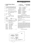
FIG. 1 is a perspective vieW of an electrical pressure Washer
35
the detected conditions to a user for diagnostic/problem
tripped, and the AC poWer to the motor Will be cut off as a
result. In such a situation, the pressure Washer can be put back
in operation by simply resetting the GFCI. Nevertheless, an
shooting purposes;
FIG. 2 is a schematic functional diagram that identi?es
40
inexperienced user Who is unaWare of the existence and/or
function of the GFCI may think that pressure Washer is bro
ken. As another example, When the pressure Washer is put in
the chemical suction mode, the pressure of the Water jet is
signi?cantly loWer than that in the normal operation mode. A
for reporting problems and diagnostic information provided
45
by indicators on the pres sure Washer;
FIG. 4 is a schematic diagram shoWing a poWer cord of an
embodiment of the pressure Washer With a plug having a
built-in ground fault circuit interrupter (GFCI) and Wiring for
50
55
markets Where GFCI is not required;
FIG. 5 is a schematic diagram shoWing an optically
coupled sensing circuit over a breaker of the GFCI for sensing
Whether AC poWer is present at the plug;
FIG. 6 is an electronic circuit schematic diagram shoWing
a diagnostic circuit in the pressure Washer for detecting opera
tion conditions of the pressure Washer and operating light
emitting diodes to indicate the detected operation conditions;
FIG. 7 is a schematic diagram shoWing a pressure Washer
of an embodiment that transmits RF signals for Wireless com
cost for providing consumer services. When a user plugs in a
neWly purchased pressure Washer and does not get the
expected high-pressure Water jet, he may think that the
components of the electrical pressure Washer;
FIG. 3 is a schematic diagram depicting a user of the
electrical pressure Washer contacting a remote service center
user, hoWever, may not knoW or remember to check that the
pressure Washer is in the chemical suction mode and may
jump to the conclusion that the pressure Washer is defective.
Also, the pressure Washer Will not Work properly if the AC
voltage supplied to it is loW, Which may happen if the user
plugs the pressure Washer into a long extension cord, Which
introduces a substance voltage drop due to the large amount
of current draWn by the pressure Washer.
Thus, inexperienced users often ?nd it dif?cult to identify
the reasons Why their electrical pressure Washers do not Work
as expected. Such dif?culties present a serious problem to the
manufacturer of the pressure Washers due to the increased
that implements an embodiment of the invention for detecting
operation conditions of the pressure Washer and indicating
60
machine is defective and decide to return it to the store Where
munication With a monitoring device; and
FIG. 8 is a schematic diagram shoWing a pressure Washer
of another embodiment that has a global positioning system
module.
he bought it. The allegedly bad machine is then returned the
DETAILED DESCRIPTION OF THE INVENTION
manufacturer even if it is fully functional. A user may also call
in for service under Warranty When his pressure Washer stops
pumping Water. As a result, a service technician may have to
be dispatched to service the machine in the ?eld, even if the
problem can be simply corrected by resetting the GFCI
65
Turning to the draWings and referring ?rst to FIG. 1, an
electrical pressure Washer 10 in an embodiment of the inven
tion includes a housing 11 that contains an electrical motor 12
US 8,074,668 B2
3
4
(FIG. 2) for pressuriZing Water received from a loW-pressure
the pressure Washer to stop Working normally can incur tre
mendous overheads for the manufacturer or distributor of the
pressure Washer in handling unnecessary returns or providing
?eld service for conditions that can be easily corrected.
In accordance With a feature of the invention, a diagnostic
circuit 36 is provided in the electrical pressure Washer 10 for
detecting operating conditions of the pressure Washer, and a
Water source through a Water inlet 13 (FIG. 2) to provide an
output high-pressure Water stream. A poWer cord 14 of a
pre-selected length connects the pressure Washer to an AC
outlet 16 from Which the pressure Washer draws the poWer
needed for operating the motor. An on/off sWitch 17 on the
housing 11 of the pressure Washer is used to turn the pressure
Washer on or off by connecting or breaking the AC poWer to
the motor. On the distal end of the poWer cord 14 is anAC plug
18 to be plugged into a receptacle of the AC outlet 16. In the
illustrated embodiment, the poWer cord includes a ground
diagnostic indication panel 38 is provided With indicator
lights 39 to indicate the detected operation conditions for
vieWing by the user. The diagnostic indication panel 38
alloWs the user to see easily the operating conditions of the
fault circuit interrupter (GFCI) 20 that is integrated With the
AC plug 18. The GFCI is not required, hoWever, in regions
Washer, so that the user can take proper corrective actions
Where the electrical safety code does not call for such a
device. The pressure Washer 10 further includes a ?exible
high-pressure hose 21. One end of the pressure hose has a
based on the diagnostic information shoWn by the indicator
lights. For instance, if an indicator light shoWs that the GFCI
20 is tripped, the user can correct the problem easily by
resetting the GFCI. Information about Which action to take
connector 22 that can be connected to a ?tting 24 on the
based on Which indicator light is on or off may be provided in
housing to form a leak-proof connection. The other end of the
hose 21 is connected to an application Wand 25 With a trigger
26 for opening or closing a valve in the Wand to control the
a trouble shooting chapter in the user’s manual for the pres
sure Washer. Even if the user lacks the technical knoWledge to
20
Water How. The pressure Washer further includes a noZZle 28
that can be connected to the Wand 25 such that pressurized
cator lights alloWs the user to report the problem to a remote
service center, Which can then identify the possible causes of
Water is ejected through an output opening 29 of the noZZle
the problem based on the status of the indicator lights. For
When the user pulls the trigger 26 on the Wand 25. The siZe of
the output opening 29 of the noZZle 28 is preferably adjustable
25
noZZle to be adjusted from a Wide “fan” spray to a focused
lights in the diagnostic indicator panel 38 of the pressure
Washer. Based on that information, the service representative
30
pressure Washer includes a chemical tank 31 for containing
the liquid detergent 32. A vacuum generated by the pressur
28. When the pressure Washer is put in the chemical suction
mode, the pressure of the Water stream ejected through the
noZZle is signi?cantly loWer than that When the pressure
Washer is in the normal operation mode.
As mentioned before, the operation of the pressure Washer
10 is affected by various factors, and there are multiple con
ditions that Will make the pressure Washer appear that it is not
function properly. Such conditions are often dif?cult to
understand or identify by an inexperienced user Who has not
read the manual for the pressure Washer or cannot compre
hend the explanations and instructions in the manual. As a
result, the user tends to assume that the pressure Washer is
broken or faulty, even though some of the conditions affecting
the performance of the machine can be easily corrected. For
instance, if the GFCI 20 on the plug 18 of the poWer cord is
normal operation mode. In this Way, the user 40 can have the
35
40
long extension cord betWeen the pressure Washer and the AC
Wall outlet 16 instead of plugging the poWer cord directly into
the Wall outlet, a substantial voltage drop may develop across
the extension cord due to the resistance of the extension cord
and the large amount of current draWn by the motor 12 of the
pressure Washer. As a result, the voltage seen by the motor is
45
housing 11 of the pressure Washer. The diagnostic circuit 36
38, Which is mounted on the housing at a location that is easily
50
vieWable but Well protected from accidental impact. In the
embodiment shoWn in FIG. 1, the diagnostic indication panel
38 is located on the upper front surface of the housing adja
cent a handle 15 of the pressure Washer. The indicator panel
38 includes lights for indicating, for example, the presence of
55
60
signi?cantly loWer than the standard AC voltage, causing the
sign that there is something Wrong With the pressure Washer.
Such inability of the user to identify the true problems causing
service person. The contacts betWeen the user 40 and the
service center 42 is, of course, not limited to a telephone
conversation and can be made via, for example, e-mail or
video conferencing over the Internet, or other forms of remote
operates indicator lights 39 in the diagnostic indication panel
pressure of the Water stream to drop noticeably. Moreover, a
user may forget that the Washer is put in the chemical suction
mode, and vieW the Weaker Water stream in that mode as a
problem corrected easily and promptly. As a result, the user is
much less likely to unnecessarily return the machine to the
shop, send the machine in for repair, or call for a visit by a
communications.
To protect the diagnostic circuit 36 from exposure to Water
or other elements, the diagnostic circuit is mounted inside the
tripped, AC poWer is cut off at the plug end of the poWer cord,
and the pressure Washer 10 cannot be turned on by operating
the on/off sWitch 17 on the housing. Also, if the user inserts a
43 can make a decision or informed guess of What the cause
of the problem may be, and give the user instructions over the
telephone to try various corrective measures to change the
operation conditions to put the pressure Washer back in the
like may be added to the Water stream. To that end, the
iZed Water pumped out through the noZZle 28 is used to
provide suction of the detergent from the chemical tank. The
detergent extracted by the vacuum from the chemical tank is
mixed With the Water stream and ejected through the noZZle
instance, as shoWn in FIG. 3, the user 40 can contact a service
center 42 of the manufacturer via telephone and tells the
service representative 43 the On/Off states of the indicator
to alloW the pressuriZed Water stream coming out of the
pencil-thin stream.
Referring noW to FIG. 2, to provide enhanced clearing
poWer of the pressurized Water stream, liquid detergent or the
understand the meaning of the indicator lights or to folloW the
instructions in the manual to correct the problems, the indi
65
the AC poWer at the GFCI plug, the AC voltage seen by the
motor, Whether the over-temperature protection for the motor
is on, Whether the pressure Washer is in the chemical suction
mode, etc. Indicators for other types of operation conditions
may also be included.
In accordance With a feature of a preferred embodiment,
the amount of electrical current draWn by the motor 12 of the
pressure Washer is detected and used to determine several
operation conditions of the pressure Washer. To that end, in
accordance With another feature of the embodiment, the
amount of the electrical current is determined by detecting the
voltage drop across one of the poWer conductors in the poWer
cord 14. In the illustrated embodiment, the voltage drop is
measured across the Return Wire of the poWer cord. As shoWn
in FIG. 4, the plug 18 With integral GFCI receives the Hot,
US 8,074,668 B2
5
6
Return, and Ground components of the standard AC voltage
nostic circuit includes LED’s 70-77 that are marked respec
(e. g., 120V) from a Wall outlet or the like. On the other side of
tively on the display panel (FIG. 1) as “Check GFCI,” “No AC
Power,” “AC OK,” “AC LoW,” “Motor OK,” “Detergent ON,”
“LoW Water Flow,” and “Motor Over-temperature,” respec
the plug, the poWer cord 14 connecting the plug to the pres
sure Washer main body includes a Hot Wire 50, a Return Wire
51, and a Ground Wire 52. The voltage drop across the Return
Wire 51 provides a useful indication of the current draWn by
tively.
the motor 12. For instance, as measured on one pressure
detected voltage drop over the Return Wire 51 divided by the
knoWn resistance of the Wire provides the amount of current
and to reduce the cost for implementing the circuitry, loW-cost
operational ampli?es (OpAmp) 81-84 are used to detect the
different operation conditions. The OpAmps 81-84 are of a
loW-poWer type to further reduce the poWer consumption of
the diagnostic circuit. The OpAMps 81-84 are connected to
respective indicator LED’s 72-76 to selectively turn the
?oWing through the Wire.
LED’s on or off depending on the operation conditions
To measure the voltage drop over the Return Wire 51 of the
poWer cord, a sensing Wire 54 is added to the standard three
Wires 50-52 of the poWer cord 14 and runs along the three
Wires. Thus, the poWer cord 14 noW contains four Wires: Hot,
detected. In the implementation of FIG. 6, the OpAmps 81-84
are used basically as voltage comparators. Each OpAmp
compares an input voltage With a reference voltage (via
appropriate voltage dividers), Which is provided by a Zener
diode 88 (DIODE 16) in the circuit of FIG. 6. The input
voltage for each OpAmp is a voltage derived from voltages
detected in the electrical system of the pressure Washer. Such
detected voltages include the AC poWer voltages and, as
mentioned above, the voltage drop over the Return Wire as
To simplify the control logic of the diagnostic circuit 36
Washer, a 36.5-foot Return Wire of l 6 AWG has a resistance of
about 0.173 ohm. With a current draW of 9- l 7Amps, a voltage
drop of about 1 .5-3 Vrms is created over the Return Wire. The
Return, Neutral, and the sensing Wire. The sensing Wire 54
alloWs the diagnostic circuit 36 to detect the voltage on the
Return Wire at the remote plug end of the poWer cord.
20
Turning to FIG. 5, the sensing Wire further alloWs the
diagnostic circuit 18 to detect Whether the AC poWer is
present at the plug 18 before the GFCI breaker 56. Since for
safety reasons the sensing Wire 54 should not have a direct
electrical contact With the plug input upstream of the GFCI
breaker 56, an optical coupling assembly 57 is used to sense
the presence ofAC poWer. As shoWn in FIG. 5, a light emitting
circuit 56 comprising a simple poWer supply and a light
emitting diode (LED) 59 is connected across the Hot terminal
61 and Return terminal 62 at the input end of the plug 18.
When AC poWer is present at the plug upstream of the GFCI,
the LED 59 is energized to emit light. On the other side of the
GFCI breaker 56, the sensing Wire 54 is connected to a pho
totransistor 60 that is positioned to receive the light generated
by the LED 59. If the LED 59 is on, the phototransistor 60 is
turned on by the light received from the LED. On the other
hand, if the LED 59 is off due to the absence of anAC voltage
betWeen the Hot and Return terminals 61 and 62, the pho
totransistor 60 is off. Based on the on/off state of the pho
totransistor 60 as sensed through the sensing Wire 54, the
diagnostic circuit 18 can decide Whether AC poWer is present
detected through the sensing Wire.
In accordance With a feature of the embodiment, the volt
25
30
age detected through the sensing Wire enables the determina
tion of multiple operation conditions. As already described
above, the sensed voltage at the plug end of the poWer cord 14
is used together With the voltage detected at the motor to
determine Whether there is no AC poWer at the plug 18 or the
GFCI breaker 56 may be open. In the circuit of FIG. 6, the
voltage drop over the Return Wire is further used to determine
Whether the motor is in normal operation condition (i.e.,
“Motor OK”), Whether the pres sure Washer is in the chemical
suction mode (i.e., “Detergent On”), Whether the inlet Water
35
pressure is loW (i.e., “LoW Water Flow”), or Whether the
thermal protection circuit for the motor is opened to prevent
the motor from overheating (i.e., “Motor Over-temperature”).
40
As described above, the voltage drop over the Return Wire can
be used to determine the root mean square (rms) value of the
current folloWing through the motor 12 of the pressure
Washer. It has been experimentally discovered in connection
at the plug input.
With this invention that the root mean square values of the
Referring noW to FIG. 6, the detection of the presence of
AC poWer at the plug before the GFCI in turn alloWs the
diagnostic circuit to determine Whether the GFCI breaker 56
is open. IfAC poWer is present at the plug but not at the motor,
the diagnostic circuit 18 can deduce that the GFCI breaker 56
is open, and can indicate this condition by turning on an
indicator light 70 marked “Check GFCI.” On the other hand,
if no AC poWer is detected at the plug input, the diagnostic
current draWn by the motor 12 corresponding to these four
operation conditions fall into four separate ranges. When the
pressure Washer is operating normally, the motor current
stays in a hi gh-current range, and varies depending to differ
ent degrees on the AC rms voltage at the motor, the type of
noZZle used, and the shape of the output Water stream at the
noZZle. When the pressure Washer is in the chemical suction
mode, the motor current is signi?cantly loWer than that of the
normal operation. When the inlet Water pressure is loW, the
45
50
circuit turns on a “No AC” indicator light 71 to indicate that
there is no AC poWer. This condition may occur if, for
instance, the user forgets to connect the plug to a Wall outlet
or if a circuit breaker before the Wall outlet is open.
To poWer the diagnostic indication assembly so that the
indicators can be used to indicate the operation conditions
even after the AC poWer is cut off, a backup capacitor 80 of a
loW Water ?oW causes the motor current to ?uctuate rapidly,
55
suf?ciently large value (e.g., 0.1 farad) is used in the diagnos
tic circuit to store energy. If the On/Off sWitch 17 on the
pressure Washer is in the On position but the AC poWer to the
60
pressure Washer is cut off, the capacitor 80 is automatically
sWitched in to poWer the components of the diagnostic circuit
but the averaged value of the motor current is fairly stable and
stays beloW the motor current in the chemical suction mode,
thus providing a good indication of the presence of the loW
inlet pressure condition. When the thermal protection circuit
in the motor Winding is opened, the motor is not draWing any
current. The lack of motor current together With the detection
that the AC voltage is detected at the motor indicates that the
thermal protection circuit in the motor may be opened.
In according With another feature of the embodiment, to
minimiZe the current required to operate the LED’s, the
36.
LED’s 72-77 are connected in series such that the same cur
To reduce the energy consumption of the diagnostic indi
cation assembly that includes the diagnostic circuit and the
indication panel, light-emitting diodes (LED’s) are used as
the indicator lights. In the illustrated embodiment, the diag
rent (hereinafter “the indicator current”) can ?oW through
65
selected LED’s to turn those LED’s on. The ef?ciency of
poWer usage is further enhanced by using the indicator cur
rent 90 to charge the backup capacitor 80 by connecting the
US 8,074,668 B2
7
8
capacitor in series to the chain of LED’s. During operation,
111 can pinpoint its current location. The communication
circuit 101 of the pressure Washer 110 then transmits RF
When the AC poWer is available, the indicator current ?oWs
signals containing information of its current location, its iden
ti?cation, and its operational status as detected by the diag
nostic circuit 36. The transmission and reception of the RF
signals may utiliZe the infrastructure provided by a cellular
phone netWork. When the RF signals is received by the ser
through one or more of the LED’s 72-77 depending on the
operation conditions detected by the OpAmps 81-84, and
?oWs into the backup capacitor 80 to charge the capacitor
until the voltage across the capacitor reaches a value set by the
Zener diode 91. When the AC poWer is cut off, the energy
stored in the backup capacitor 80 is used to poWer the opera
tion of the diagnostic circuit 36 to turn either of the LED’s 70
vice station 103 or a mobile monitoring unit 104, the service
technician 106 can learn the identity of the pressure Washer,
Where the machine is, and Whether the machine is operating
properly. Thus, if the pressure Washer 110 is left in the ?eld or
is stolen, the RF transmission sent by the communication
and 71 on to indicate to the user that the GFCI should be
checked or there is no AC poWer at the plug 18.
To control the On/Off state of each of the LED’s 72-77, a
plurality of bypass transistors 92-97 are provided such that
each LED has a corresponding bypass transistor connected in
parallel thereWith. When the bypass transistor is turned on,
the indicator current Will ?oW through the bypass transistor
instead of the LED. As a result, the LED is turned off, i.e., it
does not emit light. The On/ Off state of the bypass transistor
is controlled by an associated OpAmp depending on Whether
the operating condition monitored by that OpAmp is present.
By Way of example, if the pressure Washer is being used and
the motor 12 is running normally, the voltage drop over the
circuit 101 of the pressure Washer can be used to track the
location of the pressure Washer, and the identi?cation infor
mation encoded in the transmission alloWs the receiver to
identify the pressure Washer. The identi?cation information
in the Wireless transmission also alloWs the monitoring device
to remotely monitor the inventory of pressure Washers at a
store. To that end, the GPS locator function of the machine
20
Return Wire is of a value indicating that the motor current is in
the high range. The voltage drop is presented as one of the
input voltages for the OpAmp 82. The other input voltage is
103 over RF transmission.
25
derived from the reference voltage via a voltage divider. The
input voltages for the OpAmp 82 cause the output voltage of
the OpAmp to be at a loW value that turns the bypass transistor
94 off. With the bypass transistor 94 turned off, the indication
current ?oWs through the LED 74. As a result, the LED 74
generates light to indicate that the motor is operating nor
30
What is claimed is:
1. An electrical pressure Washer comprising:
35
enables the receiver of the RF transmission from the machine
to determine the status of the pres sure Washer in the ?eld and,
if necessary, to contact the user of the pressure Washer to
a housing including a Water inlet port and a Water outlet
Port;
the housing containing an electrical motor that is adapted
to pressuriZe Water received through the Water inlet port
and to output pres suriZed Water through the Water outlet
sure Washer 100 can be used for various purposes. For
mobile monitoring device 104. Moreover, the RF transmis
sion may also include diagnostic data indicative of the opera
tion conditions detected by the diagnostic circuit 36. This
and should not be taken as limiting the scope of the invention.
Therefore, the invention as described herein contemplates all
following claims and equivalents thereof.
(RF) transceiver 102 to send and receive radio frequency
signals. The Wireless communication capability of the pres
instance, the RF communication circuit may serve the func
tion of a tracking device. To that end, the communication
circuit may be programmed to transmit the serial number of
the pressure Washer, and/or other information that may be
used to identify the pressure Washer. The RF transmission
may be received by a receiver at a service center 103, or by a
In vieW of the many possible embodiments to Which the
principles of this invention may be applied, it should be
recogniZed that the embodiments described herein With
respect to the draWing ?gures are meant to be illustrative only
such embodiments as may come Within the scope of the
mally.
In an alternative embodiment as shoWn in FIG. 7, a pres
sure Washer 100 is equipped With a communication circuit
101. The communication circuit controls a radio frequency
may be activated at the time the pressure Washer 110 is pur
chased by a customer at a store. The GPS locating transmis
sion from the pressure Washer 10 may also be triggered in
response to commands sent remotely by the service center
40
Port;
an application Wand connected to the Water outlet by a hose
and having a noZZle for outputting the pressuriZed Water;
the housing further including a diagnostic circuit and an
indication panel;
45
a poWer cord connected to the electrical motor for deliver
ing AC poWer to the electrical motor and having a plug at
a distal end;
Wherein the diagnostic circuit includes a plurality of opera
tional ampli?ers, each operational ampli?er determin
50
correct the problem to restore the normal operation of the
Washer.
Alternatively, the pres sure Washer may be equipped With a
modem 105. The communication circuit 101 is programmed
such that it automatically dials up to a pre-programmed num
ber of the service center 103 When the modem is plugged into
a telephone line. Once the phone connection is made, the
communication circuit 101 transmits information including
the serial number of the pressure Washer and the operation
55
conditions. This enables a service technician 106 at the ser
60
ing the presence of a different operation condition of the
pressure Washer based on a comparison betWeen a
detected voltage drop over a return Wire of the poWer
cord and a corresponding reference voltage;
Wherein the indication panel comprises a plurality of indi
cator lights that are connected to the diagnostic circuit,
With each indicator light each corresponding to said
different operation condition and being adapted to be
illuminated When the diagnostic circuit has determined
that the respective operation condition is present.
2. The electrical pressure Washer of claim 1, Wherein one of
vice center 103 to identify the potential problems of the unit
Without having to physically examine the machine.
the respective operation conditions is that the electrical motor
In yet another embodiment as shoWn in FIG. 8, the pres sure
3. The electrical pressure Washer of claim 1, Wherein one of
the respective operation conditions is that a Water pressure at
Washer 110 is further equipped With a global positioning
system (GPS) module 111. The GPS module 111 receives
radio signals from GPS satellites 112. By triangulation of
signals from three of the GPS satellites 112 the GPS module
is operational.
65
the Water input port is loW.
4. The electrical pressure Washer of claim 1, further com
prising a chemical tank for storing a liquid detergent, and
US 8,074,668 B2
9
10
wherein one of the respective operation conditions is that the
pressure Washer is in a mode of extracting the liquid detergent
from the chemical tank for mixing With Water received
Wherein the diagnostic circuit further detects Whether an
through the inlet port.
Wherein the plug further includes a light emitter on an input
end of the plug and an optical receiver connected to the
AC voltage is present at the plug before the ground fault
circuit interrupter; and
5. The electrical pressure Washer of claim 1, Wherein one of
sensing Wire, the light emitter emitting light When an AC
voltage is present at the plug.
the respective operation conditions is that a thermal protec
tion circuit of the electrical motor is open for protecting the
electrical motor from overheating.
16. An electrical device comprising:
6. The electrical pressure Washer of claim 1, Wherein one of
an electrical motor;
the respective operation conditions is that anAC voltage at the
a sensing circuit;
electrical motor is loW.
a poWer cord having a plug at a distal end for connecting
AC poWer to the electrical motor, the poWer cord having
a Hot Wire, a Return Wire, a Ground Wire, and a sensing
7. The electrical pressure Washer of claim 1, Wherein the
plug of the poWer cord includes a ground fault circuit inter
rupter.
Wire connected to the sensing circuit for the sensing
circuit to detect a voltage at the plug, Wherein the plug
8. The electrical pressure Washer of claim 1, further includ
ing a sensing Wire connecting the diagnostic circuit to the
distal end of the poWer cord for detecting the voltage drop
plug and an optical receiver connected to the sensing
over the return Wire of the poWer cord.
Wire, the light emitter emitting light When anAC voltage
further includes a light emitter on an input end of the
9. The electrical pressure Washer of 8, further comprising a
ground fault circuit interrupter, Wherein the diagnostic circuit
20
circuit interrupter,
further detects Whether a breaker of the ground fault circuit
Wherein the sensing circuit further detects through the
sensing Wire Whether a breaker of the ground fault cir
interrupter is open.
10. The electrical pressure Washer of claim 9, Wherein the
diagnostic circuit further detects Whether an AC voltage is
present at the plug before the ground fault circuit interrupter.
is present at the plug, and
Wherein the plug of the poWer cord has a ground fault
25
cuit interrupter is open and Whether an AC voltage is
present at the plug before the ground fault circuit inter
rupter;
11. The electrical pressure Washer of claim 1, Wherein the
plurality of indicator lights are light emitting diodes.
Wherein the sensing circuit senses a voltage drop over the
12. The electrical pressure Washer of claim 11, Wherein a
Return Wire by detecting the voltage at the plug, the
subgroup of the light emitting diodes are Wired in series.
13. The electrical pressure Washer of claim 12, Wherein
each light emitting diode in the subgroup has a bypass tran
voltage drop being indicative of an amount of current
draWn by the electrical motor; and
Wherein the electrical device is a pressure Washer compris
ing: a Water inlet port for receiving Water from a Water
30
sistor connected inparallel With said each light emitting diode
for selectively diverting current aWay from said each light
source; a Water outlet port, Wherein the electrical motor
emitting diode.
is in ?uid communication With the Water inlet port and
the Water outlet port for pressurizing the Water received
14. The electrical pressure Washer of claim 13, Wherein the
35
diagnostic circuit includes a backup capacitor for poWering
through the Water inlet port and pumping the pressurized
the diagnostic circuit in absence of AC poWer, and Wherein
the backup capacitor is connected in series to the light emit
ting diodes in the subgroup such that a current for energizing
Water through the Water outlet port; and an application
Wand connected to the Water outlet by a hose and having
a nozzle for outputting a pressurized Water stream.
17. The electrical pressure Washer of claim 16, Wherein the
sensing circuit detects an operation condition of the pressure
Washer based on the voltage drop, and Wherein the pressure
Washer further includes an indication panel having at least
one indicator light for indicating the detected operation con
dition.
18. The electrical pressure Washer of claim 16, Wherein the
the light emitting diodes also charges the backup capacitor.
40
15. An electrical pressure Washer comprising:
a Water inlet port for receiving Water from a Water source;
a Water outlet port;
an electrical motor in ?uid communication With the Water
inlet port and the Water outlet port for pressurizing the
Water received through the Water inlet port and pumping
the pressurized Water through the Water outlet port;
45
operation condition detected by the sensing circuit is that the
electrical motor is operational.
an application Wand connected to the Water outlet by a hose
and having a nozzle for outputting a pressurized Water
stream;
50
Water pressure at the Water input port is loW.
20. The electrical pressure Washer of claim 17, Wherein the
pressure Washer further includes a chemical tank for storing a
a poWer cord having a plug at a distal end for connecting
AC poWer to the electrical motor;
a diagnostic circuit for detecting a voltage drop over the
poWer cord and determining an operation condition
based on the voltage drop;
an indication panel having at least one indicator light for
liquid detergent, and Wherein the operation condition
55
indicating the operation condition;
a sensing Wire connecting the diagnostic circuit to the
distal end of the poWer cord for detecting the voltage
drop over the poWer cord;
a ground fault circuit interrupter, Wherein the diagnostic
circuit further detects Whether a breaker of the ground
fault circuit interrupter is open;
19. The electrical pressure Washer of claim 17, Wherein the
operation condition detected by the sensing circuit is that a
detected by the sensing circuit is that the pressure Washer is in
a mode of extracting the liquid detergent from the chemical
tank for mixing in the Water stream.
21. The electrical pressure Washer of claim 17, Wherein the
60
operation condition detected by the sensing circuit is that a
thermal protection circuit of the electrical motor is open for
protecting the electrical motor from overheating.
*
*
*
*
*