1
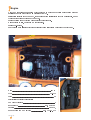
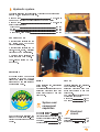
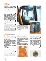
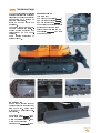
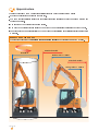
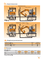
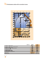
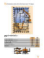
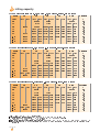
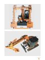
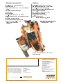
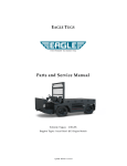
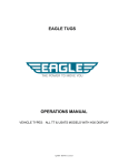
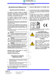
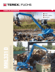
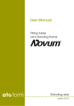
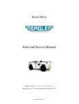
CX75 SR_Copertina 22-03-2006 17:49 Pagina 1
C
CX
M
Y
CM
MY
CY CMY
K
SERIES HYDRAULIC EXCAVATORS
Colori compositi
CX75SR
Engine
A very low fuel consuming engine which conforms to European requirements for “low exhaust
emission” Tier 2 in accordance with directive 97/68/EC.
Particularly suitable for urban work, these engines have significantly reduced noise levels, one of
the lowest fuel consumptions on the market.
Engine rotation speed checking via an electric potentiometer.
Manual return to idle, control on RH control lever.
Engine pre-heating.
High performance filtration circuit enables oil change intervals to be extended to every 500 h.
Make........................................................................................... ISUZU
Type ......................................................................................... CC-4JG1
Turbo................................................................................................. No
Electrically controlled fuel injection
Number of cylinders ........................................................................... 4
Bore x stroke ................................................................ 95.4 x 107 mm
Capacity.................................................................................. 3059 cm3
Power at 2100 rpm EEC 80/1269 ........................... 39.1 kW - 52.4 hp
CX75 SR - 00
2
Hydraulic system
2 variable displacement axial piston hydraulic pumps feeding the
attachment, the travel and the swing.
Maximum flow................................................................ 2 x 71.4 l/min
1 gear pump feeding the dozer blade and the boom offset
Maximum flow................................................................ 1 x 25.4 l/min
Safety valve pressure:
Attachment............................................................................. 294 bar
Swing...................................................................................... 226 bar
Travel ...................................................................................... 294 bar
Dozer blade, boom offset ...................................................... 226 bar
CONTROL VALVES
4 control valve sections for the
RH travel, boom, bucket and
dipper acceleration.
5 control valve sections for LH
travel, dipper, swing, auxiliary
circuit and boom acceleration.
2 control valve sections for
dozer blade and boom offset.
Load-holding valves on boom
and dipper.
FILTRATION
Hydraulic system components
protected by “ULTRA CLEAN”
filter which filters out particles SWING
larger than 1µ and also traces of
condensation water.
Fixed displacement, axial piston
swing motor.
Upperstructure swing speed 10 rpm
Planetary reduction gear with
automatic braking by oil bath
disc brakes.
TRAVEL
Variable displacement, axial piston hydraulic motors.
Planetary reduction gear with
automatic braking by oil bath
disc brakes.
Two travel speeds (selected on
the instrument panel)
High speed ..................... 4.9 kph
Low speed ...................... 3.4 kph
System and
component
capacities
Electrical
Hydraulic reservoir.............. 50 l
Hydraulic system ................. 95 l
circuit
High performance filtration for Travel reduction gear (per side). 1.3 l
longer hydraulic fluid life-time Engine (with filter change).. 9.6 l Voltage ................................. 12 v
(fluid change interval now 5000 Fuel tank ............................ 100 l Alternator......................... 50 A/h
hours).
Cooling system.................... 9.6 l Starter motor........ 12 v - 2.2 kW
CX75 SR - 00
3
Cab
With CASE machines, "smaller
machine dimensions" don't
mean that there is less space for
the operator. The CX75SR cab
has the same level of comfort
and convenience as the standard
models in the CX range; it is
integrated with the upperstructure and therefore does not
affect manoeuvrability on 360°
swing. It’s still wide enough to
provide the operator with maximum comfort and all the advantages of a "standard" machine,
including mechanical suspension and a multi-adjustable driver's seat, with a storage compartment to the rear LH of the
seat.
Mechanical suspension, multiadjustable driver’s seat (with a
storage compartment to the rear
LH of the seat).
The cab has a large roof window, enabling continuous checking of the bucket position when
the attachment is fully retracted.
For operator comfort, the cab
is insulated from vibration
and noise by four elastofluid
mountings.
Attachments
To meet user requirements,
CASE "short radius" crawler
excavators are suitable for every
type of work-site.
These machines are mainly used
on the following types of work:
• Construction and maintenance of high speed roads and
urban streets.
• Construction in residential
areas.
• Demolition.
• Forestry work.
• Machine hire companies.
To provide best possible profitability in the various sorts of
work encountered, machine
configuration needs to be able to
be changed quickly and easily:
CX75 SR - 00
4
THE ”CASE” ANSWERS
of implement, using suppleA
choice
of
one-piece
or
double
mentary hydraulic functions
•
offset boom for digging verti- (swing, tool orientation, etc.)
cal walled trenches, regardless • Reduced maintenance costs
of their depth.
using EMS (Easy Maintenance
• A choice of different dipper System) which is standard on
lengths.
the boom foot and head linkages. This system, which is
• “MULTIFIT” quick coupler.
used on the heavy CX
• Supply to the most varied types also
machines, provides a considerable reduction in maintenance intervals (every 1000 h).
Undercarriage
LC type undercarriage providing
excellent stability (as a result of
its length) and loading capacity
comparable to machines of
standard dimensions.
Steel or rubber tracks are
available.
Upper and lower tracks equipped with bushings and seals.
Travel motors protected and
incorporated in the undercarriage.
Track tension adjustable by
grease cylinder.
SPECIFICATIONS
(per track set)
Number of upper rollers.......... 1
Number of lower rollers.......... 5
Number of track pads............ 39
Type of track pads Triple grousers
Optional Rubber track pads
Standard track pad size 450 mm
Gradeability ............... 70% (35°)
Front chain guide
DOZER BLADE
Dozer blade control lever at
console height to the right hand
side of the cab. Dozer blade
movement by a central hydraulic cylinder.
Dozer blade width............. 2.32 m
Dozer blade height .......... 0.450 m
Maximum raising height 0.415 m
Maximum underground
lowering depth................. 0.205 m
CX75 SR - 00
5
Upperstructure
The “short radius” CX75SR has special specifications compared to “standard” models:
• Shorter upperstructure radius for the rear part.
boom foot is positioned close to the upperstructure swing axis so as to have the minimum attachment
• The
front swing radius.
• Cab is within the upperstructure swing radius .
• The width of upperstructure is close to the width of the undercarriage (using standard track pads).
and general stability of the machine provides lifting capacities identical to “standard”
• Counterweight
machines.
RESPECT OF ENVIRONMENT
The excavator respects the European “reduced noise level” as per directive 2000/14/EC Phase 2.
Standard models
Ø 3.60 m
Radius mini = 1.80 m
Standard models
Swing radius = 1.20 m
CX75 SR - 00
6
General dimensions
Monobloc boom
2,23 m
5,92 m* / 5,91 m**
1,16 m
R=1,21 m
2,70 m
2,70 m* / 2,95 m**
1,07 m
0,45 m
CX75
SR
0,36 m
2,21 m
2,85 m
1,87 m
3,28 m
2,32 m
* With 1.70 m dipper
** With 2.10 m dipper
4,49 m
Offset boom - dipper 1.75 m
2,23 m
5,97 m
1,16 m
R=1,21 m
2,70 m
2,97 m
1,07 m
0,45 m
CX75
SR
0,36 m
2,21 m
2,85 m
1,87 m
3,28 m
2,32 m
4,55 m
Weight and ground pressure
Shoes 450 mm - bucket
operator and full fuel tank
Monobloc boom - 1.70 m dipper
Offset boom and 1.75 m dipper
Weight
(kg)
7660
8060
Ground
Pressure (bar)
0.34
0.36
Buckets
General purpose
SAE capacity
Width
Weight
Litres
mm
kg
110
300
117
130
350
125
140
400
138
160
450
145
240
600
170
310
750
200
360
850
220
Other types of bucket on application.
CX75 SR - 00
7
Performance data with monobloc boom
8m
25'
20'
15'
10'
5'
0
25'
7m
6m
20'
5m
F
15'
G
4m
3m
E
2m
CX75SR
1m
0
1m
B
DH
5'
A
2m
3m
C
2.44 m
10'
4m
15'
5m
8m
7m
6m
A Maximum digging reach
B Maximum digging reach at ground level
C Maximum digging depth
D Digging depth 2.44 m (8‘) level bottom
E Maxi dump height
F Overall reach height
G Minimum swing radius
H Vertical straight wall dig depth
Digging force
Breakout force
CX75 SR - 00
8
5m
4m
3m
2m
1m
0
dipper :
1.70 m
6.50 m
6.40 m
4.15 m
3.80 m
5.25 m
7.35 m
1.80 m
3.65 m
3830 daN
5690 daN
2.10 m
6.90 m
6.75 m
4.55 m
4.25 m
5.55 m
7.60 m
2.10 m
4.10 m
3300 daN
5690 daN
Performance data with offset boom and 1.75 dipper
8m
25'
20'
15'
10'
5'
0
25'
7m
6m
20'
5m
15'
4m
F
G
3m
E
2m
CX75SR
1m
0
1m
H
5'
A
2m
3m
B
C D
2.44 m
10'
4m
15'
5m
7m
6m
5m
4m
3m
2m
1m
0
Maximum working range (zero offset)
Trench with vertical walls (maximum offset)
Maximun
offset
6.10 m
5.95 m
3.75 m
3.40 m
4.85 m
6.85 m
1.95 m
2.85 m
3940 daN
5690 daN
0,185 m
1,10 m
1,00 m
A Maximum digging reach
B Maximum digging reach at ground level
C Maximum digging depth
D Digging depth 2.44 m (8‘) level bottom
E Maxi dump height
F Overall reach height
G Minimum swing radius
H Vertical straight wall dig depth
Digging force
Breakout force
Zero
offset
6.50 m
6.35 m
4.20 m
3.80 m
5.15 m
7.20 m
2.25 m
3.25 m
3940 daN
5690 daN
CX75 SR - 00
9
Lifting capacity
CX75SR with dozer blade down - 3.85 m boom - 1.70 m dipper - Bucket - 450 mm shoes
Reach
2m
3m
4m
5m
maxi
Height
front 360° front 360° front 360° front 360° front 360°
5m
1600*
1680*
1600*
4m
1770*
1710*
1550* 1270
3m
2990*
2240*
1910* 1700 1750* 1160 1590* 1060
2m
2890* 2540 2210* 1610 1880* 1120 1700* 960
1m
3440* 2360 2490* 1520 2020* 1080 1860* 920
0m
2490*
3670* 2260 2670* 1460 2100* 1040 1940* 940
-1 m
3900*
3620* 2230 2670* 1430 2050* 1030 2040* 1020
-2 m
4640*
3310* 2240 2450* 1430
2150* 1240
-3 m
3600*
2600* 2300
2240* 1870
CX75SR with dozer blade down - 3.85 m boom - 2.10 m dipper - Bucket - 450 mm shoes
Reach
2m
3m
4m
5m
maxi
Height
front 360° front 360° front 360° front 360° front 360°
5m
1430*
1390*
4m
1490*
1510* 1210 1350* 1100
3m
1920*
1710*
1600* 1180 1370* 940
2m
2580*
2030* 1630 1760* 1130 1440* 850
1m
3210* 2390 2350* 1530 1920* 1080 1580* 820
0m
2570*
3570* 2260 2580* 1460 2050* 1040 1770* 820
-1 m
3540*
3640* 2200 2660* 1410 2070* 1010 1860* 890
-2 m
4970* 4590 3450* 2190 2540* 1400
1970* 1040
-3 m
4150*
2930* 2230 2100* 1430
2080* 1410
CX75SR with dozer blade down - offset boom - 1.75 m dipper - Bucket - 450 mm shoes
Reach
2m
3m
4m
5m
maxi
Height
front 360° front 360° front 360° front 360° front 360°
5m
1570*
1570*
4m
1730*
1600*
1550* 1270
3m
2140*
1780* 1640 1600* 1080 1580* 1010
2m
2680* 2400 2030* 1500 1710* 1020 1620* 880
1m
3130* 2110 2270* 1360 1820* 940 1690* 810
0m
3320* 1950 2400* 1260 1880* 890 1770* 810
-1 m
3920*
3240* 1890 2390* 1210
1870* 880
-2 m
4090* 4060 2940* 1910 2180* 1210
1990* 1080
-3 m
3130*
2290* 2000
2080* 1730
Maxi reach
m
4.1
4.8
5.3
5.5
5.5
5.4
5.0
4.4
3.4
Maxi reach
m
4.6
5.3
5.7
5.9
5.9
5.8
5.5
4.9
4.0
Maxi reach
m
4.0
4.7
5.2
5.4
5.4
5.3
4.9
4.3
3.3
- Lift capacities are taken in accordance with SAE J 1097
- Lift capacities shown in kg do not exceed 75% of the tipping load or 87% of the hydraulic lift capacity.
- Capacities that are marked with an asterisk are hydraulic limited
- If the machine is equipped with a quick coupler, subtract the weight of the quick coupler from the load shown in the tables to calculate the real
lifting capacity.
CX75 SR - 00
10
2.10 m
CX75 SR - 00
11
Standard equipment
• One-piece boom or double offset boom
• Steel tracks 450 mm
• High performance “ULTRA CLEAN” (1µ) filtration
system
• “Auxiliary” control valve section
• Dozer blade
• 2 travel speeds
• Load-holding valves (boom and dipper)
• Tier 2 engine (reduced smoke emissions and noise
level)
• Electric motor speed control
• Automatic engine speed return to idle
• RH, LH and rear rear-view mirror
(safety when swinging and
reversing)
Options
• Single-acting system (“hammer” type)*
• “Multipurpose” circuit (hammer or shears)*
• Double-acting circuit (shears, etc.)*
• 2nd auxiliary circuit (clamshell orientation type)*
• Backhoe-clamshell circuit*
• “MULTIFIT” Hydraulic quick coupler
• FOPS (roof) cab protection
• Self-regulating air conditioning
• Rubber tracks 450 mm
• Safety valves (boom - dipper)
* Note: availability of these circuits varies depending on
the type of boom and length of the dipper
Standard and optional equipment can vary from
country to country
WORLDWIDE CASE CONSTRUCTION
EQUIPMENT CONTACT INFORMATION
EUROPE/AFRICA/MIDDLE EAST:
CENTRE D’AFFAIRES EGB
5, AVENUE GEORGES BATAILLE - BP 40401
60671 LE PLESSIS-BELLEVILLE - FRANCE
NORTH AMERICA/MEXICO:
700 STATE STREET
RACINE, WI 53404 U.S.A.
LATIN AMERICA:
AV. GENERAL DAVID SARNOFF 2237
32210 - 900 CONTAGEM - MG
BELO HORIZONTE BRAZIL
NOTE: Standard and optional fittings can vary
according to the demands and specific
regulations of each country. The illustrations
may include optional rather than standard
fittings - consult your Case dealer. Furthermore,
CNH reserves the right to modify machine
specifications without incurring any obligation
relating to such changes.
Conforms to directive 98/37/CE
CNH UK Ltd.
Armstrong House
The Finningley Estate
Hayfield Lane
Doncaster
DN9 3XA
Fax +44 (0)1302 802126
www.casece.com
Form No. 26051038GB - Printed in Italy - LEADER Firenze - 03/06
ASIA PACIFIC:
UNIT 1 - 1 FOUNDATION PLACE - PROSPECT
NEW SOUTH WALES - 2148 AUSTRALIA
CHINA:
No. 29, INDUSTRIAL PREMISES, No. 376.
DE BAO ROAD, WAIGAOQIAO FTZ, PUDONG,
SHANGHAI, 200131, P.R.C.