1
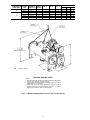
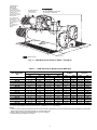
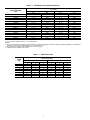
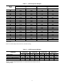
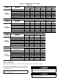
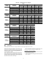
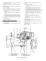
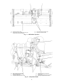
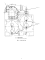
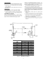
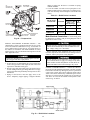
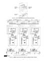
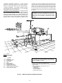
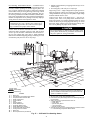
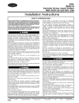
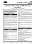
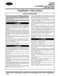
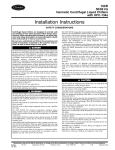
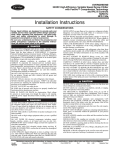
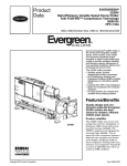
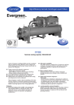
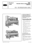
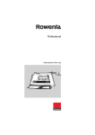
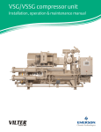
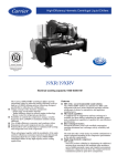
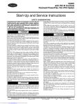
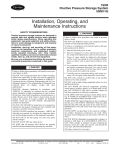
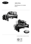
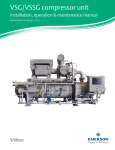
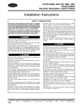
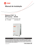
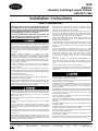
19XR
50/60 Hz
Hermetic Centrifugal Liquid Chillers
with HFC-134a
Installation Instructions
SAFETY CONSIDERATIONS
Centrifugal liquid chillers are designed to provide safe
and reliable service when operated within design specifications. When operating this equipment, use good judgment and safety precautions to avoid damage to equipment and property or injury to personnel.
Be sure you understand and follow the procedures and
safety precautions contained in the machine instructions, as well as those listed in this guide.
DO NOT VENT refrigerant relief devices within a building. Outlet from
rupture disc or relief valve must be vented outdoors in accordance with
the latest edition of ANSI/ASHRAE 15 (American National Standards
Institute/American Society of Heating, Refrigeration and Air-Conditioning
Engineers) (Safety Code for Mechanical Refrigeration). The accumulation of refrigerant in an enclosed space can displace oxygen and cause
asphyxiation.
PROVIDE adequate ventilation in accordance with ANSI/
ASHRAE 15, especially for enclosed and low overhead spaces. Inhalation of high concentrations of vapor is harmful and may cause heart
irregularities, unconsciousness, or death. Intentional misuse can be fatal. Vapor is heavier than air and reduces the amount of oxygen available for breathing. Product causes eye and skin irritation. Decomposition products are hazardous.
DO NOT USE OXYGEN to purge lines or to pressurize a machine for
any purpose. Oxygen gas reacts violently with oil, grease, and other
common substances.
DO NOT USE air to leak test. Use only refrigerant or dry nitrogen.
NEVER EXCEED specified test pressures. VERIFY the allowable test
pressure by checking the instruction literature and the design pressures
on the equipment nameplate.
DO NOT VALVE OFF any safety device.
BE SURE that all pressure relief devices are properly installed and functioning before operating any machine.
RISK OF INJURY OR DEATH by electrocution. High voltage is present
on motor leads even though the motor is not running when a solid state
or inside-delta mechanical starter is used. Open the power supply disconnect before touching motor leads or terminals.
DO NOT WELD OR FLAMECUT any refrigerant line or vessel until
all refrigerant (liquid and vapor) has been removed from chiller. Traces
of vapor should be displaced with dry air or nitrogen and the work area
should be well ventilated. Refrigerant in contact with an open flame
produces toxic gases.
DO NOT USE eyebolts or eyebolt holes to rig machine sections or the
entire assembly.
DO NOT work on high-voltage equipment unless you are a qualified
electrician.
DO NOT WORK ON electrical components, including control
panels, switches, starters, or oil heater until you are sure ALL POWER
IS OFF and no residual voltage can leak from capacitors or solid-state
components.
LOCK OPEN AND TAG electrical circuits during servicing. IF WORK
IS INTERRUPTED, confirm that all circuits are deenergized before
resuming work.
AVOID SPILLING liquid refrigerant on skin or getting it into the eyes.
USE SAFETY GOGGLES. Wash any spills from the skin with soap
and water. If liquid refrigerant enters the eyes, IMMEDIATELY FLUSH
EYES with water and consult a physician.
NEVER APPLY an open flame or live steam to a refrigerant cylinder.
Dangerous over pressure can result. When it is necessary to heat refrigerant, use only warm (110 F [43 C]) water.
DO NOT REUSE disposable (nonreturnable) cylinders or attempt to
refill them. It is DANGEROUS AND ILLEGAL. When cylinder is emptied, evacuate remaining gas pressure, loosen the collar, and unscrew
and discard the valve stem. DO NOT INCINERATE.
CHECK THE REFRIGERANT TYPE before adding refrigerant to the
machine. The introduction of the wrong refrigerant can cause
machine damage or malfunction.
Operation of this equipment with refrigerants other than those cited
herein should comply with ANSI/ASHRAE15 (latest edition). Contact
Carrier for further information on use of this machine with other
refrigerants.
DO NOT ATTEMPT TO REMOVE fittings, covers, etc., while
machine is under pressure or while machine is running. Be sure pressure is at 0 psig (0 kPa) before breaking any refrigerant connection.
CAREFULLY INSPECT all relief valves, rupture discs, and other
relief devices AT LEAST ONCE A YEAR. If machine operates
in a corrosive atmosphere, inspect the devices at more frequent
intervals.
DO NOT ATTEMPT TO REPAIR OR RECONDITION any
relief valve when corrosion or build-up of foreign material (rust, dirt,
scale, etc.) is found within the valve body or mechanism. Replace the
valve.
DO NOT install relief devices in series or backwards.
USE CARE when working near or in line with a compressed spring.
Sudden release of the spring can cause it and objects in its path to act
as projectiles.
DO NOT STEP on refrigerant lines. Broken lines can whip about and
release refrigerant, causing personal injury.
DO NOT climb over a machine. Use platform, catwalk, or staging. Follow safe practices when using ladders.
USE MECHANICAL EQUIPMENT (crane, hoist, etc.) to lift or move
inspection covers or other heavy components. Even if components are
light, use mechanical equipment when there is a risk of slipping or
losing your balance.
BE AWARE that certain automatic start arrangements CAN ENGAGE
THE STARTER, TOWER FAN, OR PUMPS. Open the disconnect ahead
of the starter, tower fan, and pumps. Shut off the machine or pump
before servicing equipment.
USE only repaired or replacement parts that meet the code requirements of the original equipment.
DO NOT VENT OR DRAIN waterboxes containing industrial brines,
liquid, gases, or semisolids without the permission of your process control group.
DO NOT LOOSEN waterbox cover bolts until the waterbox has been
completely drained.
DOUBLE-CHECK that coupling nut wrenches, dial indicators, or other
items have been removed before rotating any shafts.
DO NOT LOOSEN a packing gland nut before checking that the nut
has a positive thread engagement.
PERIODICALLY INSPECT all valves, fittings, and piping for corrosion, rust, leaks, or damage.
PROVIDE A DRAIN connection in the vent line near each pressure
relief device to prevent a build-up of condensate or rain water.
Manufacturer reserves the right to discontinue, or change at any time, specifications or designs without notice and without incurring obligations.
Book 2
PC 211
Catalog No. 531-940
Printed in U.S.A.
Form 19XR-2SI
Pg 1
10-97
Replaces: 19XR-1SI
Tab 5a
CONTENTS
1. Inspect for shipping damage while machine is still on shipping conveyance. If machine appears to be damaged or
has been torn loose from its anchorage, have it examined
by transportation inspectors before removal. Forward claim
papers directly to transportation company. Manufacturer
is not responsible for any damage incurred in transit.
2. Check all items against shipping list. Immediately notify
the nearest Carrier representative if any item is missing.
3. To prevent loss or damage, leave all parts in original packages until beginning installation. All openings are closed
with covers or plugs to prevent dirt and debris from entering machine components during shipping. A full operating oil charge is placed in the oil sump before
shipment.
Page
SAFETY CONSIDERATIONS . . . . . . . . . . . . . . . . . . 1
INTRODUCTION . . . . . . . . . . . . . . . . . . . . . . . . . . . . . 2
General . . . . . . . . . . . . . . . . . . . . . . . . . . . . . . . . . . . . . 2
Job Data . . . . . . . . . . . . . . . . . . . . . . . . . . . . . . . . . . . . 2
INSTALLATION . . . . . . . . . . . . . . . . . . . . . . . . . . . . . 2-35
Receiving the Machine . . . . . . . . . . . . . . . . . . . . . . . 2
• INSPECT SHIPMENT
• IDENTIFY MACHINE
• PROVIDE MACHINE PROTECTION
Rigging the Machine . . . . . . . . . . . . . . . . . . . . . . . . . 2
• RIG MACHINE ASSEMBLY
• RIG MACHINE COMPONENTS
Install Machine Supports . . . . . . . . . . . . . . . . . . . . 17
• INSTALL STANDARD ISOLATION
• INSTALL ACCESSORY ISOLATION
• INSTALL SPRING ISOLATION
Connect Piping . . . . . . . . . . . . . . . . . . . . . . . . . . . . . 19
• INSTALL WATER PIPING TO HEAT
EXCHANGERS
• INSTALL VENT PIPING TO
RELIEF VALVES
Make Electrical Connections . . . . . . . . . . . . . . . . 28
• CONNECT CONTROL INPUTS
• CONNECT CONTROL OUTPUTS
• CONNECT STARTER
• CARRIER COMFORT NETWORK INTERFACE
Install Field Insulation . . . . . . . . . . . . . . . . . . . . . . 35
INSTALLATION START-UP REQUEST
CHECKLIST . . . . . . . . . . . . . . . . . . . . . . . . CL-1, CL-2
IDENTIFY MACHINE — The machine model number,
serial number, and heat exchanger sizes are stamped on
machine identification nameplate (Fig. 1 and 2). Check this
information against shipping papers and job data.
PROVIDE MACHINE PROTECTION — Protect machine
and starter from construction dirt and moisture. Keep protective shipping covers in place until machine is ready for
installation.
If machine is exposed to freezing temperatures after water
circuits have been installed, open waterbox drains and remove all water from cooler and condenser. Leave drains open
until system is filled.
Rigging the Machine — The 19XR machine can be
rigged as an entire assembly. It also has flanged connections
that allow the compressor, cooler, and condenser sections to
be separated and rigged individually.
RIG MACHINE ASSEMBLY — See rigging instructions on
label attached to machine. Also refer to rigging guide
(Fig. 3 and 4), physical data in Fig. 5, and Tables 1-8B. Lift
machine only from the points indicated in rigging guide. Each
lifting cable or chain must be capable of supporting the entire weight of the machine.
INTRODUCTION
General — The 19XR machine is factory assembled, wired,
and leak tested. Installation (not by Carrier) consists
primarily of establishing water and electrical services to
the machine. The rigging, installation, field wiring, field piping, and insulation of waterbox covers are the responsibility
of the contractor and/or customer. Carrier has no installation
responsibilities for the equipment.
Job Data
Necessary information consists of:
• job contract or specifications
• machine location prints
• rigging information
• piping prints and details
• field wiring drawings
• starter manufacturer’s installation details
• Carrier certified print
Lifting machine from points other than those specified
may result in serious damage to the unit and personal
injury. Rigging equipment and procedures must be adequate for machine weight. See Fig. 3 and 4 for machine weights.
NOTE: These weights are broken down into component sections for use when installing the unit in
sections. For the complete machine weight, add all component sections and refrigerant charge together. See
Tables 4-8B for machine component weights.
INSTALLATION
IMPORTANT: Ensure that rigging cable is over the
guide bolt or cable hook on the motor end cover before lifting if cooler size is 10 through 67.
Receiving the Machine
INSPECT SHIPMENT
Do not open any valves or loosen any connections. The
standard 19XR machine is shipped with a full refrigerant charge. Some machines may be shipped with a nitrogen holding charge as an option.
2
Fig. 1 — Model Number Identification
3
FRONT TOP VIEW
1
2
3
4
5
6
7
8
9
10
11
12
13
14
15
16
17
18
19
20
21
22
—
—
—
—
—
—
—
—
—
—
—
—
—
—
—
—
—
—
—
—
—
—
Oil Level Sight Glass
Diffuser Actuator (Hidden/19XR5 Only)
Discharge Isolation Valve
Condenser Pumpout Connection
Condenser Safety Relief Valves
Three-Way Condenser Relief Valve
Hot Gas Bypass Line
Condenser Waterbox Nozzles
Cooler Waterbox Nozzles
Cooler Safety Relief Valves
Cooler Pumpout Connection
Machine Identification Nameplate
Control Panel
Refrigerant Charging Valve
Guide Vane Actuator
Compressor/Transmission
Oil Drain/Charging Valve
Oil Pump
Auxillary Power Panel
Oil Filter Isolation Valve
Oil Filter
Motor
23
24
25
26
27
28
29
30
31
32
33
34
—
—
—
—
—
—
—
—
—
—
—
—
Waterbox Vents
Oil Reclaim Filter
Float Chamber
Unit Mounted Starter
Refrigerant Filter/Drier Isolation Valves
Sight Glass/Moisture Indicator
Refrigerant Filter/Drier
Cooler Liquid Line Isolation Valve
Hot Gas Bypass Valve (Option)
Hot Gas Bypass Isolation Valve (Option)
Oil Reclaim Filter Isolation Valve
Waterbox Vents
BOTTOM REAR VIEW
Fig. 2 — Typical 19XR Installation
4
COMPRESSOR
FRAME SIZE*
2
2 or 3
3
4
COOLER
SIZE
MAXIMUM
WEIGHT (lb)
VESSEL
LENGTH
DIM. ‘‘A’’
10-12
15-17
20-22
30-32
35-37
40-42
45-47
50-52
55-57
50-52
55-57
60-62
65-67
18,500
19,000
19,500
21,000
22,500
29,700
31,800
32,200
33,200
32,530
34,230
39,950
36,950
108
128
108
128
148
128
148
128
148
128
148
128
148
48- 79
58- 99
48- 79
58- 99
78- 49
58- 99
68-109
58- 99
68-109
58- 99
68- 29
58- 99
68- 29
CHAIN LENGTH
‘‘B’’
‘‘C’’
‘‘D’’
128-79
138-09
138-09
138-69
138-29
138-39
128-79
138-09
138-09
138-69
138-29
138-39
148-29
138-49
138-49
128-89
128-89
138-49
138-19
138-29
138-89
128-79
128-99
138-59
138-19
188-39
158-99
138-19
128-99
138-49
138-79
138-19
148-49
138-19
128-99
138-49
138-79
138-19
148-49
DIM. ‘‘E’’
DIM. ‘‘F’’
28-39
28-69
38-19
28-49
38-69
28-69
38-29
28-79
38-49
28-89
*The first digit of the 3-digit compressor code indicates the frame size of the compressor.
MACHINE RIGGING GUIDE
NOTES:
1. Each cable must be capable of supporting the entire weight of the
machine. See chart for maximum weights.
2. Chain lengths shown are typical for 158 lifting height. Some minor
adjustments may be required.
Fig. 3 — Machine Rigging Guide (Cooler Size 10 Through 67)
5
COMPRESSOR
FRAME SIZE*
4
5
COOLER
SIZE
MAXIMUM
WEIGHT (lb)
VESSEL
LENGTH
DIM. ‘‘A’’
DIM. ‘‘B’’
DIM. ‘‘C’’
70-72
75-77
70-72
75-77
80-82
85-87
40,410
44,210
45,600
49,400
54,900
58,300
148
168
148
168
148
168
68- 69
78- 59
68- 29
68-119
68- 29
68-119
38-49
38-59
38-69
38-69
38-69
38-69
38-59
38-59
38-79
38-69
38-79
38-69
CHAIN LENGTH
‘‘D’’
‘‘E’’
‘‘F’’
118-69 128-59 128-99
128-09 138-39 138-69
118-69 128-59 128-99
128-09 138-39 138-69
118-69 128-59 128-99
128-09 138-39 138-69
*The first digit of the 3-digit compressor code indicates the frame size of the compressor.
CG — Center of Gravity
MACHINE RIGGING GUIDE
NOTES:
1. Each chain must be capable of supporting the entire weight of the
machine. See chart for maximum weights.
2. Chain lengths shown are typical for 158 lifting height. Some minor
adjustments may be required.
3. Dimensions ‘‘A’’ and ‘‘B’’ define distance from machine center of
gravity to tube sheet outermost surfaces. Dimension ‘‘C’’ defines
distance from machine center of gravity to floor.
Fig. 4 — Machine Rigging Guide (Cooler Size 70 Through 87)
6
TUBE REMOVAL
SPACE FOR
EITHER END
10'-0" (3048 mm)
(SIZES 10-12, 20-22)
12'-3 1/2" (3747 mm)
(SIZES 15-17)
12'-3 1/2" (3747 mm)
(SIZES 30-32, 40-42,
50-52, 60-62)
14'-3" (4343 mm)
(SIZES 35-37, 45-47,
55-57, 65-67)
14'-0" (4267 mm)
(SIZES 70-72,
80-82)
16'-0" (4877 mm)
(SIZES 75-77,
85-87)
MOTOR SERVICE
CLEARANCE
4'0"- (1219 mm)
3'0" (915 mm)
RECOMMENDED OVERHEAD
SERVICE CLEARANCE
C
2'-61/8" MIN
(362 mm)
A
B
2' MIN
(610 mm)
SERVICE AREA
Fig. 5 — 19XR Dimensions (Refer to Tables 1 Through 3)
Table 1 — 19XR Dimensions (Nozzle-In-Head Waterbox)
HEAT EXCHANGER
SIZE
10
15
20
30
35
40
45
50
55
60
65
70
75
80
85
to
to
to
to
to
to
to
to
to
to
to
to
to
to
to
12
17
22
32
37
42
47
52
57
62
67
72
77
82
87
A (Length,
2-Pass*
ft-in.
11- 37⁄8
13- 73⁄8
11- 51⁄8
13- 81⁄4
15- 43⁄4
13-11
15- 71⁄2
13-111⁄4
15- 73⁄4
13-113⁄4
15- 81⁄4
16- 4
18- 4
16- 43⁄4
18- 43⁄4
with Nozzle-in-Head Waterbox)
1 or 3 Pass†
mm
ft-in.
mm
3451
11-103⁄4
3626
4150
14- 21⁄4
4324
3483
12- 01⁄2
3670
4172
14- 31⁄4
4350
4693
15-113⁄4
4870
4242
14- 61⁄4
4426
4763
16- 23⁄4
4947
4248
14- 63⁄4
4439
4769
16- 31⁄4
4959
4261
14- 71⁄4
4451
4782
16- 33⁄4
4972
4978
17- 01⁄2
5194
5588
19- 01⁄2
5804
4997
17- 11⁄2
5220
5607
19- 11⁄2
5829
B (Width)
ft-in.
4-113⁄4
4-113⁄4
5- 53⁄4
5- 53⁄4
5- 53⁄4
6- 2
6- 2
6- 61⁄2
6- 61⁄2
6-101⁄2
6-101⁄2
7-111⁄2
7-111⁄2
8-103⁄4
8-103⁄4
mm
1518
1518
1670
1670
1670
1880
1880
1994
1994
2096
2096
2426
2426
2711
2711
C (Height)
ft-in.
6- 11⁄4
6- 11⁄4
6- 31⁄4
6- 95⁄8
6- 95⁄8
7- 03⁄4
7- 03⁄4
7- 27⁄8
7- 27⁄8
7- 47⁄8
7- 47⁄8
9- 91⁄2
9- 91⁄2
9-111⁄4
9-111⁄4
mm
1861
1861
1911
2073
2073
2153
2153
2207
2207
2257
2257
2985
2985
3029
3029
*Assumes both cooler and condenser nozzles on same end of chiller.
†1 or 3 pass length applies if either (or both) cooler or condenser is a 1 or 3 pass design.
NOTES:
1. Service access should be provided per American Society of Heating, Refrigeration, and Air Conditioning Engineers (ASHRAE) 15, latest edition,
National Fire Protection Association (NFPA) 70, and local safety code.
2. Allow at least 3 ft (915 mm) overhead clearance for service rigging.
3. Certified drawings available upon request.
7
Table 2 — 19XR Dimensions (Marine Waterbox)
A (Length, Marine Waterbox —
not shown)
HEAT EXCHANGER
SIZE
10
15
20
30
35
40
45
50
55
60
65
70
75
80
85
to
to
to
to
to
to
to
to
to
to
to
to
to
to
to
2-Pass*
1 or 3 Pass†
ft-in.
NA
NA
12- 65⁄8
14- 9
16- 51⁄2
15- 01⁄4
16- 83⁄4
15- 01⁄4
16- 83⁄4
15- 03⁄4
16- 91⁄4
17- 8
19- 8
17- 81⁄2
19- 81⁄2
12
17
22
32
37
42
47
52
57
62
67
72
77
82
87
mm
NA
NA
3826
4496
5017
4591
5099
4591
5099
4591
5112
5385
5994
5398
6007
ft-in.
NA
NA
14- 3
16- 43⁄4
18- 11⁄4
16- 83⁄4
18- 51⁄4
16- 83⁄4
18- 51⁄4
16- 91⁄4
18- 53⁄4
19-101⁄2
21-101⁄2
20- 1
22- 1
mm
NA
NA
4343
4997
5518
5099
5620
5099
5620
5111
5632
6058
6668
6121
6731
*Assumes both cooler and condenser nozzles on same end of chiller.
†1 or 3 pass length applies if cooler is a 1 or 3 pass design.
NOTES:
1. Service access should be provided per American Society of Heating, Refrigeration, and Air Conditioning Engineers (ASHRAE) 15, latest edition,
National Fire Protection Association (NFPA) 70, and local safety code.
2. Allow at least 3 ft (915 mm) overhead clearance for service rigging.
3. Certified drawings available upon request.
Table 3 — 19XR Nozzle Size
NOZZLE SIZE (in.)
(Nominal Pipe Size)
FRAME
SIZE
1
2
3
4
5
6
7
8
1-Pass
8
10
10
10
10
10
14
14
Cooler
2-Pass
6
8
8
8
8
10
12
14
3-Pass
6
6
6
6
6
8
10
12
8
1-Pass
8
10
10
10
10
10
14
14
Condenser
2-Pass
6
8
8
8
10
10
12
14
3-Pass
6
6
6
6
8
8
12
12
Table 4 — 19XR Compressor Weights
MOTOR
CODE
BD
BE
BF
BG
BH
CD
CE
CL
CM
CN
CP
CQ
DB
DC
DD
DE
DF
DG
DH
DJ
EH
EJ
EK
EL
EM
EN
EP
ENGLISH
Total Compressor Weight*
(lb)
60 Hz
50 Hz
3,755
3,755
3,805
3,805
3,870
3,870
3,950
3,950
3,950
3,950
4,659
4,756
4,685
4,771
4,710
4,842
4,737
4,868
4,751
4,883
4,806
4,898
4,874
4,898
6,112
6,158
6,138
6,224
6,216
6,262
6,224
6,351
6,274
6,412
6,364
6,466
6,412
6,868
6,466
6,977
8,025
11,135
11,085
11,265
11,160
11,282
11,181
11,435
11,271
11,435
11,335
11,635
11,434
11,605
SI
Total Compressor Weight*
(kg)
60 Hz
50 Hz
1703
1703
1726
1726
1755
1755
1792
1792
1792
1792
2134
2153
2155
2165
2137
2167
2149
2209
2156
2215
2181
2212
2211
2212
2772
2793
2822
2823
2819
2840
2823
2881
2846
2908
2886
2933
2908
3115
2933
3165
3640
5051
5028
5110
5062
5118
5072
5187
5113
5187
5142
5278
5186
5264
*Compressor weight is comprised of compressor, stator, rotor, end bell, suction elbow, and discharge elbow.
NOTE: For medium voltage motors (over 600 v), add 490 lb (222 kg).
Table 5 — 19XR Component Weights
COMPONENT
Suction Elbow
Discharge Elbow
Control Cabinet*
Optional Unit-Mounted Starter†
Optional Isolation Valves
FRAME 2
COMPRESSOR
lb
kg
50
23
60
27
30
14
800
363
115
52
FRAME 3
COMPRESSOR
lb
kg
54
24
46
21
30
14
800
363
115
52
*Included in total cooler weight.
†Weight of optional factory-mounted starter is not included and must be added to the heat
exchanger weight.
9
FRAME 4
COMPRESSOR
lb
kg
175
79
157
71
30
14
800
363
115
52
FRAME 5
COMPRESSOR
lb
kg
210
95
140
63
30
14
800
363
115
52
Table 6 — 19XR Heat Exchanger Data
ENGLISH
CODE
Dry Rigging Weight
(lb)
Cooler Condenser
Only
Only
10
11
12
15
16
17
20
21
22
30
31
32
35
36
37
40
41
42
45
46
47
50
51
52
55
56
57
60
61
62
65
66
67
70
71
72
75
76
77
80
81
82
85
86
87
2,742
2,812
2,883
3,003
3,089
3,176
3,442
3,590
3,746
4,137
4,319
4,511
4,409
4,617
4,835
5,898
6,080
6,244
6,353
6,561
6,748
7,015
7,262
7,417
7,559
7,839
8,016
8,270
8,462
8,617
8,943
9,161
9,338
12,395
12,821
13,153
13,293
13,780
14,159
16,156
16,530
16,919
17,296
17,723
18,169
2,704
2,772
2,857
2,984
3,068
3,173
3,523
3,690
3,854
3,694
3,899
4,100
4,606
4,840
5,069
6,054
6,259
6,465
6,617
6,851
7,085
7,285
7,490
7,683
7,990
8,214
8,434
8,286
8,483
8,676
9,204
9,428
9,648
13,139
13,568
13,969
14,211
14,702
15,160
15,746
16,176
16,606
17,001
17,492
17,984
SI
Dry Rigging Weight
(kg)
Machine Charge
Machine Charge
Refrigerant
Water
Refrigerant
Water Volume
Cooler Condenser
Weight
Volume
Weight
(gal)
Only
Only
Cooler Condenser Cooler Condenser
Cooler Condenser Cooler Condenser
290
200
34
42
1244
1227
132
91
129
158
310
200
37
45
1276
1257
141
91
140
170
330
200
40
49
1308
1296
150
91
152
185
320
250
39
48
1362
1354
145
113
149
183
340
250
43
52
1401
1392
154
113
163
198
370
250
47
57
1441
1439
168
113
178
216
345
225
48
48
1561
1598
156
102
183
181
385
225
55
55
1628
1674
175
102
207
210
435
225
62
63
1699
1748
197
102
234
239
350
260
55
55
1877
1676
159
118
208
210
420
260
64
65
1959
1769
190
118
242
246
490
260
72
74
2046
1860
222
118
271
282
400
310
61
62
2000
2089
181
141
232
233
480
310
70
72
2094
2195
218
141
266
273
550
310
80
83
2193
2299
249
141
301
314
560
280
89
96
2675
2746
254
127
338
365
630
280
97
106
2757
2839
286
127
368
400
690
280
105
114
2832
2933
313
127
396
433
640
330
98
106
2881
3001
290
150
372
403
720
330
108
117
2976
3108
327
150
407
442
790
330
116
127
3060
3214
358
150
438
481
750
400
115
128
3181
3304
340
181
435
483
840
400
126
137
3293
3397
381
181
477
518
900
400
133
136
3364
3484
408
181
502
552
870
490
127
142
3428
3624
395
222
481
536
940
490
139
152
3555
3725
426
222
527
575
980
490
147
162
3635
3825
445
222
557
613
940
420
144
159
3751
3758
426
190
546
601
980
420
153
168
3838
3847
445
190
578
636
1020
420
160
177
3908
3935
463
190
604
669
1020
510
160
176
4056
4174
463
231
605
668
1060
510
169
187
4155
4276
481
231
641
707
1090
510
177
197
4235
4376
494
231
671
745
1220
780
224
209
5622
5960
553
354
848
791
1340
780
243
229
5816
6154
608
354
919
867
1440
780
257
248
5966
6336
653
354
974
937
1365
925
245
234
6030
6446
619
420
927
885
1505
925
266
257
6251
6669
683
420
1009
971
1625
925
283
278
6423
6877
737
420
1072
1052
1500
720
285
264
7328
7142
680
327
1080
1000
1620
720
302
284
7498
7337
735
327
1143
1075
1730
720
319
304
7674
7532
785
327
1208
1150
1690
860
313
295
7845
7712
767
390
1183
1118
1820
860
331
318
8039
7934
826
390
1254
1205
1940
860
351
341
8241
8158
880
390
1329
1291
*Rigging weights are for standard tubes of standard wall thickness (Turbo-B3 and Spikefin 2,
0.025-in. [0.635 mm] wall).
NOTES:
1. Cooler includes the control panel (LID), suction elbow, and 1⁄2 the distribution piping weight.
2. Condenser includes float valve and sump, discharge elbow, and 1⁄2 the distribution piping
weight.
3. For special tubes refer to the 19XR Computer Selection Program.
4. All weights for standard 2 pass NIH (nozzle-in-head) design.
10
Table 7 — 19XR Additional Data for Marine Waterboxes*
HEAT EXCHANGER
FRAME, PASS
FRAME
FRAME
FRAME
FRAME
FRAME
FRAME
FRAME
FRAME
FRAME
FRAME
FRAME
FRAME
FRAME
FRAME
FRAME
FRAME
FRAME
FRAME
FRAME
FRAME
FRAME
FRAME
FRAME
FRAME
FRAME
FRAME
FRAME
FRAME
2,
2,
3,
3,
4,
4,
5,
5,
6,
6,
7,
7,
8,
8,
2,
2,
3,
3,
4,
4,
5,
5,
6,
6,
7,
7,
8,
8,
1 AND 2
2 PASS
1 AND 2
2 PASS
1 AND 3
2 PASS
1 AND 3
2 PASS
1 AND 3
2 PASS
1 AND 3
2 PASS
1 AND 3
2 PASS
1 AND 3
2 PASS
1 AND 3
2 PASS
1 AND 3
2 PASS
1 AND 3
2 PASS
1 AND 3
2 PASS
1 AND 3
2 PASS
1 AND 3
2 PASS
PASS
PASS
PASS
PASS
PASS
PASS
PASS
PASS
PASS
PASS
PASS
PASS
PASS
PASS
Psig
150
150
150
150
150
150
150
150
150
150
150
150
150
150
300
300
300
300
300
300
300
300
300
300
300
300
300
300
ENGLISH
Rigging Weight
(lb)
730
365
730
365
1060
530
1240
620
1500
750
2010
740
1855
585
860
430
860
430
1210
600
1380
690
1650
825
3100
2295
2745
1630
Water Volume
(gal)
84
42
84
42
123
61
139
69
162
81
326
163
406
203
84
42
84
42
123
61
139
69
162
81
326
163
405
203
kPa
1034
1034
1034
1034
1034
1034
1034
1034
1034
1034
1034
1034
1034
1034
2068
2068
2068
2068
2068
2068
2068
2068
2068
2068
2068
2068
2068
2068
*Add to heat exchanger data for total weights or volumes.
NOTES:
1. Weight adder shown is the same for cooler and condenser of equal frame size.
2. For the total weight of a vessel with a marine waterbox, add these values to the heat
exchanger weights (or volumes).
11
SI
Rigging Weight
(kg)
331
166
331
166
481
240
562
281
680
340
912
336
841
265
390
195
390
195
549
272
626
313
748
374
1406
1041
1245
739
Water Volume
(L)
318
159
317
159
465
231
526
263
612
306
1234
617
1537
768
318
159
317
159
465
231
526
263
612
306
1234
617
1533
768
Table 8A — 19XR Waterbox Cover Weights
ENGLISH (lb)
HEAT
EXCHANGER
WATERBOX
DESCRIPTION
COOLER/
CONDENSER
NIH, 1 Pass Cover, 150 psig
NIH, 2 Pass Cover, 150 psig
NIH, 3 Pass Cover, 150 psig
NIH/MWB End Cover, 150 psig
NIH, 1 Pass Cover, 300 psig
NIH, 2 Pass Cover, 300 psig
NIH, 3 Pass Cover, 300 psig
NIH/MWB End Cover, 300 psig
HEAT
EXCHANGER
WATERBOX
DESCRIPTION
COOLER/
CONDENSER
NIH, 1 Pass Cover, 150 psig
NIH, 2 Pass Cover, 150 psig
NIH, 3 Pass Cover, 150 psig
NIH/MWB End Cover, 150 psig
NIH, 1 Pass Cover, 300 psig
NIH, 2 Pass Cover, 300 psig
NIH, 3 Pass Cover, 300 psig
NIH/MWB End Cover, 300 psig
HEAT
EXCHANGER
WATERBOX
DESCRIPTION
COOLER/
CONDENSER
NIH, 1 Pass Cover, 150 psig
NIH, 2 Pass Cover, 150 psig
NIH, 3 Pass Cover, 150 psig
NIH/MWB End Cover, 150 psig
NIH, 1 Pass Cover, 300 psig
NIH, 2 Pass Cover, 300 psig
NIH, 3 Pass Cover, 300 psig
NIH/MWB End Cover, 300 psig
HEAT
EXCHANGER
WATERBOX
DESCRIPTION
COOLER/
CONDENSER
NIH, 1 Pass Cover, 150 psig
NIH, 2 Pass Cover, 150 psig
NIH, 3 Pass Cover, 150 psig
NIH/MWB End Cover, 150 psig
NIH, 1 Pass Cover, 300 psig
NIH, 2 Pass Cover, 300 psig
NIH, 3 Pass Cover, 300 psig
NIH/MWB End Cover, 300 psig
FRAME 1
Standard
Flanged
Nozzles
177
204
185
218
180
196
136
136
248
301
255
324
253
288
175
175
FRAME 2
Standard
Flanged
Nozzles
320
350
320
350
300
340
300
300
411
486
411
518
433
468
400
400
FRAME 3
Standard
Flanged
Nozzles
320
350
320
350
300
340
300
300
411
486
411
518
433
468
400
400
FRAME 4
Standard
Flanged
Nozzles
485
521
487
540
504
520
379
379
593
668
594
700
621
656
569
569
FRAME 5
Standard
Flanged
Nozzles
616
652
590
663
629
655
428
428
764
655
761
839
795
838
713
713
FRAME 6
Standard
Flanged
Nozzles
802
838
770
843
817
843
583
583
880
956
844
995
901
952
833
833
FRAME 7 COOLER
Standard
Flanged
Nozzles
1392
1469
1345
1461
1434
1471
1022
1022
1985
2150
1934
2174
2009
2090
1567
1567
FRAME 7 CONDENSER
Standard
Flanged
Nozzles
1205
1282
1163
1279
1222
1280
920
920
1690
1851
1628
1862
1714
1831
1923
1923
FRAME 8 COOLER
Standard
Flanged
Nozzles
1831
1909
1739
1893
1851
1909
1480
1480
2690
2854
2595
2924
2698
2861
1440
1440
FRAME 8 CONDENSER
Standard
Flanged
Nozzles
1682
1760
1589
1744
1702
1761
1228
1228
2394
2549
2269
2578
2417
2529
1767
1767
LEGEND
NIH
— Nozzle-in-Head
MWB — Marine Waterbox
NOTE: Weight for NIH 2-Pass Cover, 150 psig is included in the heat exchanger weights shown in Table 6.
RIG MACHINE COMPONENTS — Refer to instructions
below, Fig. 6-9, and Carrier Certified Prints for machine component disassembly.
Do not attempt to disconnect flanges while the machine
is under pressure. Failure to relieve pressure can result
in personal injury or damage to the unit.
IMPORTANT: Only a qualified service technician should
perform this operation.
Before rigging the compressor, disconnect all wires entering the power panel.
12
Table 8B — 19XR Waterbox Cover Weights
SI (kg)
HEAT
EXCHANGER
WATERBOX
DESCRIPTION
COOLER/
CONDENSER
NIH, 1 Pass Cover, 150 psig
NIH, 2 Pass Cover, 150 psig
NIH, 3 Pass Cover, 150 psig
NIH/MWB End Cover, 150 psig
NIH, 1 Pass Cover, 300 psig
NIH, 2 Pass Cover, 300 psig
NIH, 3 Pass Cover, 300 psig
NIH/MWB End Cover, 300 psig
HEAT
EXCHANGER
WATERBOX
DESCRIPTION
COOLER/
CONDENSER
NIH, 1 Pass Cover, 150 psig
NIH, 2 Pass Cover, 150 psig
NIH, 3 Pass Cover, 150 psig
NIH/MWB End Cover, 150 psig
NIH, 1 Pass Cover, 300 psig
NIH, 2 Pass Cover, 300 psig
NIH, 3 Pass Cover, 300 psig
NIH/MWB End Cover, 300 psig
HEAT
EXCHANGER
WATERBOX
DESCRIPTION
COOLER/
CONDENSER
NIH, 1 Pass Cover, 150 psig
NIH, 2 Pass Cover, 150 psig
NIH, 3 Pass Cover, 150 psig
NIH/MWB End Cover, 150 psig
NIH, 1 Pass Cover, 300 psig
NIH, 2 Pass Cover, 300 psig
NIH, 3 Pass Cover, 300 psig
NIH/MWB End Cover, 300 psig
HEAT
EXCHANGER
WATERBOX
DESCRIPTION
COOLER/
CONDENSER
NIH, 1 Pass Cover, 150 psig
NIH, 2 Pass Cover, 150 psig
NIH, 3 Pass Cover, 150 psig
NIH/MWB End Cover, 150 psig
NIH, 1 Pass Cover, 300 psig
NIH, 2 Pass Cover, 300 psig
NIH, 3 Pass Cover, 300 psig
NIH/MWB End Cover, 300 psig
FRAME 1
Standard
Flanged
Nozzles
80
93
84
99
82
89
62
62
112
137
116
147
115
131
79
79
FRAME 2
Standard
Flanged
Nozzles
145
159
145
159
136
154
136
136
186
220
186
235
196
212
181
181
FRAME 3
Standard
Flanged
Nozzles
145
159
145
159
140
154
136
136
186
220
186
235
196
212
181
181
FRAME 4
Standard
Flanged
Nozzles
220
236
221
245
229
236
172
172
269
303
269
318
282
298
258
258
FRAME 5
Standard
Flanged
Nozzles
279
296
268
301
285
297
194
194
347
381
345
398
361
380
323
323
FRAME 6
Standard
Flanged
Nozzles
364
380
349
382
371
381
265
265
399
434
383
451
409
432
378
378
FRAME 7 COOLER
Standard
Flanged
Nozzles
631
666
610
663
650
667
464
464
900
975
877
986
911
948
711
711
FRAME 7 CONDENSER
Standard
Flanged
Nozzles
547
582
528
580
554
581
417
417
767
840
738
845
777
831
872
872
FRAME 8 COOLER
Standard
Flanged
Nozzles
831
866
789
859
840
866
671
671
1220
1295
1177
1326
1224
1298
653
653
FRAME 8 CONDENSER
Standard
Flanged
Nozzles
763
798
721
791
772
799
557
557
1086
1156
1029
1169
1096
1147
802
802
LEGEND
NIH
— Nozzle-in-Head
MWB — Marine Waterbox
NOTE: Weight for NIH 2-Pass Cover, 150 psig is included in the heat exchanger weights shown in Table 6.
NOTE: If the cooler and condenser vessels must be separated, the heat exchangers should be kept level by placing a
support plate under the tube sheets. The support plate will
also help to keep the vessels level and aligned when the vessels are bolted back together.
NOTE: Wiring must also be disconnected. Label each wire
before removal (see Carrier Certified Prints). In order to disconnect the starter from the machine, remove wiring for the
oil pump, oil heater, control wiring at the power panel, and
the main motor leads at the starter lugs.
Remove all transducer and sensor wires at the sensor. Clip
all wire ties necessary to pull heat exchangers apart.
To Separate Cooler and Condenser:
1. Place a support plate under each tube sheet to keep each
vessel level (Fig. 6, Item 6).
2. Cut the refrigerant motor cooling line at the location shown
(Fig. 6, Item 7).
13
3. Disconnect the motor refrigerant return line (Fig. 6,
Item 8).
4. Disconnect the following:
a. compressor oil sump temperature sensor cable
(Fig. 8, Item 4)
b. bearing temperature sensor cable (Fig. 8, Item 2).
c. motor temperature sensor cable (Fig. 8, Item 1)
d. wires and cable housings that cross from the power
panel to the starter and control panel (Fig. 7, Item 2)
e. discharge temperature sensor cable (Fig. 8, Item 6)
f. compressor oil sump pressure cable (Fig. 8, Item 3)
g. compressor oil discharge pressure cable (Fig. 8,
Item 5)
h. guide vane actuator cable (Fig. 7, Item 1).
i. diffuser actuator cable (Frame 5 compressor only —
not shown)
5. Disconnect the flared fitting for the oil reclaim line
(Fig. 6, Item 3).
6. Unbolt the compressor discharge elbow (Fig. 7, Item 3).
7. Cover all openings.
8. Disconnect motor power cables at the starter lugs
(Fig. 6, Item 4).
9. Unbolt the compressor mounting from the cooler
(Fig. 6, Item 9).
10. Rig the compressor.
3. Disconnect the compressor discharge elbow at the compressor (Fig. 7, Item 3).
4. Cut the hot gas bypass line at the location shown (Fig. 6,
Item 1).
5. Unbolt the cooler liquid feed line at the location shown
(Fig. 6, Item 10).
6. Cover all openings.
7. Disconnect all wires and cables that cross from the cooler
side of the machine to the condenser side, including:
a. temperature sensor cable at the waterbox (Fig. 9,
Item 1)
b. condenser transducer cable at the transducer (Fig. 7,
Item 4)
c. motor power wires at the starter (Fig. 6, Item 4)
d. wires and cable housings at the power panel that cross
from the starter to the power panel (Fig. 7, Item 2).
8. Disconnect the rabbet-fit connectors on the tube sheets
(Fig. 6, Item 5).
9. Rig the vessels apart.
To Separate the Compressor from the Cooler:
1. Unbolt the compressor suction elbow at the cooler flange
(Fig. 6, Item 2).
2. Cut the refrigerant motor cooling line at the location shown
(Fig. 6, Item 7).
1
2
3
4
5
—
—
—
—
—
Optional Hot Gas Bypass (Cut)
Compressor Suction Elbow (Unbolt)
Oil Reclaim Line (Unbolt)
Starter Connector (Unbolt)
Vessel Connectors (Unbolt)
6
7
8
9
10
—
—
—
—
—
Tube Sheet
Refrigerant Motor Cooling Line (Cut)
Motor Drain (Unbolt)
Compressor Mounting (Unbolt)
Cooler Liquid Feed Line (Unbolt)
Fig. 6 — Cooler, Side View
14
3 — Compressor Discharge Elbow Joints
4 — Condenser Transducer Cable
1 — Guide Vane Actuator Cable
2 — Power Panel to Starter Cables (Oil Pump Power,
Control Power, and Communication)
Fig. 7 — 19XR Chiller Top View
4 — Compressor Oil Sump Temperature
Sensor Cable
5 — Compressor Oil Discharge Pressure Cable
6 — Discharge Temperature Sensor Cable
1 — Motor Temperature Sensor Cable
2 — Bearing Temperature Sensor Cable
Connection (Inside Box)
3 — Compressor Oil Sump Pressure Cable
Fig. 8 — Compressor Detail
15
1 — Guide Vane Actuator
2 — Diffuser Actuator
3 — Water Temperature Sensor Cables
Fig. 9 — Chiller End View
16
INSTALL ACCESSORY ISOLATION (if required) — Uneven floors or other considerations may dictate the use of
accessory soleplates (supplied by Carrier for field installation) and leveling pads. Refer to Fig. 10 and 12.
Level machine by using jacking screws in isolation soleplates. Use a level at least 24-in. (600 mm) long.
For adequate and long lasting machine support, proper grout
selection and placement is essential. Carrier recommends that
only pre-mixed, epoxy type, non-shrinking grout be used for
machine installation. Follow manufacturer’s instructions in
applying grout.
1. Check machine location prints for required grout
thickness.
2. Carefully wax jacking screws for easy removal from grout.
3. Grout must extend above the base of the soleplate and
there must be no voids in grout beneath the plates.
4. Allow grout to set and harden, per manufacturer’s instructions, before starting machine.
5. Remove jacking screws from leveling pads after grout has
hardened.
To Rig Compressor
NOTE: The motor end of the 19XR compressor is heavy
and will tip backwards unless these directions are followed:
1. Cut two 4 in. × 6 in. wooden beams to the same length
as the compressor.
2. Drill holes into the beams and bolt them to the base of
the compressor.
Additional Notes
1. Use silicon grease on new O-rings when refitting.
2. Use gasket sealant on new gaskets when refitting.
3. Cooler and condenser vessels may be rigged vertically.
Rigging should be fixed to all 4 corners of the tube sheet.
Install Machine Supports
INSTALL STANDARD ISOLATION — Figures 10 and 11
show the position of support plates and shear flex pads, which
together form the standard machine support system.
DIMENSIONS (ft-in.)
A
B
10- 71⁄4
4-111⁄4
12-103⁄4
4-111⁄4
1
10- 7 ⁄4
5- 51⁄4
12-103⁄4
5- 41⁄4
14- 71⁄4
5- 41⁄4
12-103⁄4
6- 0
14- 71⁄4
6- 0
12-103⁄4
6- 51⁄2
14- 71⁄4
6- 51⁄2
12-103⁄4
6- 91⁄2
1
14- 7 ⁄4
6- 91⁄2
15- 17⁄8
7-101⁄2
17- 17⁄8
7-101⁄2
15- 17⁄8
8- 93⁄4
7
17- 1 ⁄8
8- 93⁄4
HEAT EXCHANGER
SIZE
10-12
15-17
20-22
30-32
35-37
40-42
45-57
50-52
55-57
60-62
65-67
70-72
75-77
80-82
85-87
Fig. 10 — 19XR Machine Footprint
17
INSTALL SPRING ISOLATION — Spring isolation may
be purchased as an accessory from Carrier for field installation. It may also be field supplied and installed. Spring isolators may be placed directly under machine support plates
or located under machine soleplates. See Fig. 13. Consult
job data for specific arrangement. Low profile spring isolation assemblies can be field supplied to keep the machine at
a convenient working height.
Obtain specific details on spring mounting and machine
weight distribution from job data. Also, check job data for
methods to support and isolate pipes that are attached to spring
isolated machines.
NOTES:
1. Dimensions in ( ) are in millimeters.
2. Isolation package includes 4 shear flex pads.
VIEW Y-Y
Fig. 11 — Standard Isolation
ACCESSORY SOLEPLATE DETAIL
VIEW X-X
LEGEND
HRS — Hot Rolled Steel
NOTES:
1. Dimensions in ( ) are in millimeters.
2. Accessory (Carrier supplied, field installed) soleplate package
includes 4 soleplates, 16 jacking screws and leveling pads.
3. Jacking screws to be removed after grout has set.
4. Thickness of grout will vary, depending on the amount necessary
to level chiller. Use only pre-mixed non-shrinking grout, Ceilcote
648CP 08-11⁄29 (38.1) to 08-21⁄49 (57) thick.
Fig. 12 — Accessory Isolation
NOTE: The accessory spring isolators are supplied by Carrier for installation in the field.
Fig. 13 — 19XR Accessory Spring Isolation
(Shown with Accessory Soleplates)
18
2. Provide openings in water piping for required pressure
gages and thermometers. For thorough mixing and temperature stabilization, wells in the leaving water pipe should
extend inside pipe at least 2 in. (50 mm).
3. Install air vents at all high points in piping to remove air
and prevent water hammer.
4. Install pipe hangers where needed. Make sure no weight
or stress is placed on waterbox nozzles or flanges.
5. Water flow direction must be as specified in Fig. 15-18.
NOTE: Entering water is always the lower of the 2 nozzles.
Leaving water is always the upper nozzle for cooler or
condenser.
6. Water flow switches must be of vapor-tight construction
and must be installed on top of pipe in a horizontal run
and at least 5 pipe diameters from any bend.
7. Install waterbox vent and drain piping in accordance with
individual job data. All connections are 3⁄4-in. FPT.
8. Install waterbox drain plugs in the unused waterbox drains
and vent openings.
9. Install optional pumpout system or pumpout system and
storage tank as shown in Fig. 19-22.
Connect Piping
INSTALL WATER PIPING TO HEAT EXCHANGERS —
Install piping using job data, piping drawings, and procedures outlined below. A typical piping installation is shown
in Fig. 14.
Factory-supplied insulation is not flammable but can be
damaged by welding sparks and open flame. Protect insulation with a wet canvas cover.
Remove chilled and condenser water sensors before
welding connecting piping to water nozzles. Refer to
Fig. 9. Replace sensors after welding is complete.
1. Offset pipe flanges to permit removal of waterbox cover
for maintenance and to provide clearance for pipe cleaning. No flanges are necessary with marine waterbox
option; however, water piping should not cross in front
of the waterbox or access will be blocked.
*
*
LEGEND
COM — Common
N.O. — Normally Open
*Do not tap connections after shutoff valve.
Fig. 14 — Typical Nozzle Piping
19
NOZZLE-IN HEAD WATERBOXES
FRAMES 1, 2, AND 3
FRAMES 4, 5, AND 6
NOZZLE ARRANGEMENT CODES FOR ALL 19XR NOZZLE-IN-HEAD WATERBOXES
PASS
1
2
3
In
8
5
7
4
7
4
COOLER WATERBOXES
Arrangement
Out
Code*
5
A
8
B
9
C
6
D
6
E
9
F
PASS
1
2
3
In
11
2
10
1
10
1
CONDENSER WATERBOXES
Arrangement
Out
Code*
2
P
11
Q
12
R
3
S
3
T
12
U
*Refer to certified drawings.
Fig. 15 — Piping Flow Data (NIH, Frames 1 Through 6)
20
NOZZLE-IN-HEAD WATERBOXES
FRAMES 7 AND 8
NOZZLE ARRANGEMENT CODES FOR ALL 19XR NOZZLE-IN-HEAD WATERBOXES
PASS
1
2
3
In
8
5
7
4
7
4
COOLER WATERBOXES
Arrangement
Out
Code*
5
A
8
B
9
C
6
D
6
E
9
F
PASS
1
2
3
In
11
2
10
1
10
1
CONDENSER WATERBOXES
Arrangement
Out
Code*
2
P
11
Q
12
R
3
S
3
T
12
U
*Refer to certified drawings.
Fig. 16 — Piping Flow Data (NIH, Frames 7 and 8)
21
MARINE WATERBOXES
FRAMES 2 AND 3*
*There is no Frame 1 marine waterbox.
NOZZLE ARRANGEMENT CODES
PASS
1
2
3
In
8
5
7
4
7
4
COOLER WATERBOXES
Arrangement
Out
Code
5
A
8
B
9
C
6
D
6
E
9
F
In
—
—
10
1
—
—
CONDENSER WATERBOXES
Arrangement
Out
Code
—
—
—
—
12
R
3
S
—
—
—
—
Fig. 17 — Piping Flow Data (MWB, Frames 2 and 3)
22
MARINE WATERBOXES (cont)
FRAMES 4, 5, AND 6
NOZZLE ARRANGEMENT CODES
PASS
1
2
3
In
9
6
7
4
7
4
COOLER WATERBOXES
Arrangement
Out
Code
6
A
9
B
9
C
6
D
6
E
9
F
In
—
—
10
1
—
—
CONDENSER WATERBOXES
Arrangement
Out
Code
—
—
—
—
12
R
3
S
—
—
—
—
FRAMES 7 AND 8
NOZZLE ARRANGEMENT CODES
PASS
1
2
3
In
8
5
7
4
7
4
COOLER WATERBOXES
Arrangement
Out
Code
5
A
8
B
9
C
6
D
6
E
9
F
In
—
—
10
1
—
—
CONDENSER WATERBOXES
Arrangement
Out
Code
—
—
—
—
12
R
3
S
—
—
—
—
Fig. 18 — Piping Flow Data (MWB, Frames 4 Through 8)
23
Table 9 — 19XR Waterbox Nozzle Sizes
FRAME
SIZE
PRESSURE
psig (kPa)
PASS
1
150/300
(1034/2068)
2
150/300
(1034/2068)
3
150/300
(1034/2068)
4
150/300
(1034/2068)
5
150/300
(1034/2068)
6
150/300
(1034/2068)
1
2
3
1
2
3
1
2
3
1
2
3
1
2
3
1
2
3
1
2
3
1
2
3
1
2
3
1
2
3
150
(1034)
7
300
(2068)
150
(1034)
8
300
(2068)
NOMINAL PIPE SIZE (in.)
Cooler
Condenser
8
8
6
6
6
6
10
10
8
8
6
6
10
10
8
8
6
6
10
10
8
8
6
6
10
10
8
10
6
8
10
10
10
10
8
8
14
14
12
12
10
12
14
14
12
12
10
12
14
14
14
14
12
12
14
14
14
14
12
12
24
ACTUAL PIPE ID (in.)
Cooler
Condenser
7.981
7.981
6.065
6.065
6.065
6.065
10.020
10.020
7.981
7.981
6.065
6.065
10.020
10.020
7.981
7.981
6.065
6.065
10.020
10.020
7.981
7.981
6.065
6.065
10.020
10.020
7.981
10.020
6.065
7.981
10.020
10.020
10.020
10.020
7.981
7.981
13.250
13.250
12.000
12.000
10.020
12.000
12.500
12.500
11.376
11.750
9.750
11.750
13.250
13.250
13.250
13.250
12.000
12.000
12.500
12.500
12.500
12.500
11.376
11.376
DIMENSIONS
ENGLISH (ft-in.)
TANK
A
SIZE
0428 10- 5
0452 14-111⁄4
B
C
D
E
F
G
9-10
4-9
2-43⁄4 1-23⁄8 3-13⁄16 4-11
14- 41⁄2 5-07⁄8 2-81⁄2 1-41⁄4 3-47⁄16 7- 21⁄4
H
J
3-81⁄8 3- 8
4-0
3-117⁄8
K
L
M
N
P
R
S
T
2-97⁄16 3-2
0-31⁄2 4-83⁄4 1-77⁄8 1-75⁄16 3-73⁄4 5-01⁄4
3-15⁄16 3-57⁄8 0-33⁄8 7-11⁄2 1-83⁄4 1-79⁄16 3-8
5-01⁄2
SI (mm)
TANK
SIZE
0428
0452
A
B
C
D
E
F
G
H
J
K
L
M
N
P
R
S
T
3175
4553
2997
4382
1448
1546
730
826
365
413
945
1027
1499
2191
1121
1219
1118
1216
849
948
965
1064
89
86
1442
2172
505
528
491
497
1111
1118
1530
1537
NOTES:
1.
2.
3.
4.
5.
Denotes center of gravity.
Dimensions in ( ) are in millimeters.
The weights and center of gravity values given are for an empty storage tank.
For additional information on the pumpout unit, see certified drawings.
The available conduit knockout sizes are:
QTY
1
1
1
1
TRADE SIZE
1⁄29
3⁄49
19
11⁄49
LOCATION
top
bottom
middle
middle
Fig. 19 — Optional Pumpout Unit and Storage Tank
25
RATED DRY WEIGHT AND REFRIGERANT CAPACITY
ENGLISH (lb)
TANK
SIZE
TANK OD
(in.)
0428
0452
24.00
27.25
DRY
WEIGHT*
(lb)
2380
3460
MAXIMUM REFRIGERANT CAPACITY (lb)
ANSI/ASHRAE 15
UL 1963
1860
3563
1716
3286
SI (kg)
TANK
SIZE
TANK OD
(mm)
0428
0452
610
592
DRY
WEIGHT*
(kg)
1080
1569
MAXIMUM REFRIGERANT CAPACITY (kg)
ANSI/ASHRAE 15
UL 1963
844
1616
778
1491
LEGEND
ASHRAE — American Society of Heating, Refrigeration,
and Air Conditioning Engineers
OD
— Outside Diameter
UL
— Underwriters’ Laboratories
*The above dry weight includes the pumpout condensing unit weight of 210 lbs (95 kg).
Fig. 19 — Optional Pumpout Unit and Storage Tank (cont)
26
Fig. 20 — Optional Pumpout System Piping Schematic with Storage Tank
Fig. 21 — Optional Pumpout System Piping Schematic without Storage Tank
27
tubing or piping near the device is essential on springisolated machines.
4. Cover the outdoor vent with a rain cap and place a condensation drain at the low point in the vent piping to prevent water build-up on the atmospheric side of the relief
device.
OIL
RETURN LINE
CONNECTION
Table 10 — Relief Device Locations
RELIEF VALVE
OUTLET SIZE
LOCATION
SERVICE
VALVES
1-in. NPT FEMALE
Cooler
CONNECTOR
1-in.NPT FEMALE
Condenser
CONNECTOR
1-in. NPT FEMALE
Optional
CONNECTOR
Storage Tank
CONDENSER
WATER CONNECTIONS
REFRIGERANT
INLET VALVE
COMPRESSOR
MOUNTING
SPRINGS
QUANTITY
Frame 5
Compressor With
All
Frame 7 or 8
Others
Heat Exchanger
4
2
4
2
2
2
NOTE: All valves relieve at 185 psi (1275 kPa).
Make Electrical Connections — Field wiring must
be installed in accordance with job wiring diagrams and all
applicable electrical codes.
Fig. 22 — Pumpout Unit
INSTALL VENT PIPING TO RELIEF VALVES — The
19XR chiller is factory equipped with relief devices on the
cooler and condenser shells. Refer to Fig. 23 and Table 10
for size and location of relief devices. Vent relief devices to
the outdoors in accordance with ANSI/ASHRAE 15 (latest
edition) Safety Code for Mechanical Refrigeration and all
other applicable codes.
Do not run 120-v wiring into the control cabinet. The
control cabinet should only be used for additional extralow voltage wiring (50 v maximum).
Wiring diagrams in this publication (Fig. 24-31) are for
reference only and are not intended for use during actual installation; follow job specific wiring diagrams.
Refrigerant discharged into confined spaces can displace oxygen and cause asphyxiation.
Do not attempt to start compressor or oil pump (even
for a rotation check) or apply test voltage of any kind
while machine is under dehydration vacuum. Motor insulation breakdown and serious damage may result.
1. If relief devices are manifolded, the cross-sectional area
of the relief pipe must at least equal the sum of the areas
required for individual relief pipes.
2. Provide a pipe plug near outlet side of each relief device
for leak testing. Provide pipe fittings that allow vent piping to be disconnected periodically for inspection of valve
mechanism.
3. Piping to relief devices must not apply stress to the
device. Adequately support piping. A length of flexible
CONNECT CONTROL INPUTS — Connect the control input wiring from the chilled and condenser water flow switches
to the starter terminal strip. Wiring may also be specified for
a spare safety switch, and a remote start/stop contact can be
wired to the starter terminal strip. Additional spare sensors
and Carrier Comfort Network modules may be specified as
well. These are wired to the machine control panel as indicated in Fig. 24 and 25.
Fig. 23 — Relief Valve Locations
28
Fig. 24 — Carrier Comfort Network Communication Bus Wiring
LEGEND
Factory Wiring
Field Wiring
*Field supplied terminal strip must be located in control panel.
Fig. 25 — COMM1 CCN Communication Wiring For Multiple Chillers (Typical)
29
CONNECT CONTROL OUTPUTS — Connect auxiliary
equipment, chilled and condenser water pumps, and spare
alarms as required and indicated on job wiring drawings.
CONNECT STARTER — The 19XR is available with either
a unit-mounted, factory-installed starter or a free-standing,
field-installed starter (Fig. 28 and 29).
Unit Mounted, Factory-Installed Starter— Attach power leads
by connecting them from inside the starter cabinet to the line
side circuit breaker terminals. See Fig. 26 and 28. Machines
with electro-mechanical starters (wye-delta) will have a top
hat shipped with the machine if the RLA (rated load amps)
is greater than 935 amps. If the machine is equipped with a
solid-state starter, a top hat is provided if the RLA exceeds
740 amps. The top hat is shipped in the knocked-down position and must be assembled and installed on top of the starter
cabinet, over the line side circuit breaker. During assembly,
remove the access plate and use it as the cover piece of the
top hat. The top hat provides additional wire bending space
to attach line side power leads to the circuit breaker within
the starter.
IMPORTANT: Be sure to ground the power circuit in
accordance with the National Electrical Code (NEC),
applicable local codes, and job wiring diagrams. Also,
make sure correct phasing is observed for proper
rotation.
3
8
7
Piping
Control Wiring
Power Wiring
LEGEND
1
2
3
4
5
6
7
8
9
10
11
—
—
—
—
—
—
—
—
—
—
—
IMPORTANT: Wiring and piping shown are for general pointof-connection only and are not intended to show details for a
specific installation. Certified field wiring and dimensional diagrams are available on request.
Disconnect
Unit Mounted Starter
Control Cabinet
Power Panel
Vents
Pressure Gages
Chilled Water Pump
Condenser Water Pump
Chilled Water Pump Starter
Condensing Water Pump Starter
Cooling Tower Fan Starter
NOTES:
1. All wiring must comply with applicable codes.
2. Refer to Carrier System Design Manual for details regarding piping techniques.
3. Wiring not shown for optional devices such as:
• remote start-stop
• remote alarm
• optional safety device
• 4 to 20 mA resets
• optional remote sensors
Fig. 26 — 19XR with Optional Unit-Mounted Starter
30
1. Insulate each terminal by wrapping with one layer of insulation putty.
2. Overwrap putty with 4 layers of vinyl tape.
High Voltage Units — High-voltage units require special terminal preparation. Follow local electrical codes for highvoltage installation. Vinyl tape is not acceptable; a high voltage
terminal method must be used.
Connect Power Wires to Oil Pump Starter — See Fig. 30.
Connect power wires to oil pump starter mounted in machine power panel. Use separate fused disconnect or circuit
breaker as shown on job wiring diagrams and Fig. 30. Check
that power supply voltage agrees with oil pump voltage. Follow correct phasing for proper motor rotation.
Free-Standing, Field-Installed Starter — Assemble and install compressor terminal box in desired orientation, and cut
necessary conduit openings in conduit support plates. See
Fig. 27 and 29. Attach power leads to compressor terminals
in accordance with job wiring drawings, observing caution
label in terminal box. Use only copper conductors. The motor must be grounded in accordance with NEC (National Electrical Code), applicable local codes, and job wiring diagrams.
Installer is responsible for any damage caused by improper
wiring between starter and compressor motor.
IMPORTANT: Do not insulate terminals until wiring
arrangement has been checked and approved by
Carrier start-up personnel. Also, make sure correct phasing is followed for proper motor rotation.
Insulate Motor Terminals and Lead Wire Ends — Insulate
compressor motor terminals, lead wire ends, and electrical
wires to prevent moisture condensation and electrical arcing. For low-voltage units (up to 600 v), obtain insulation
material from machine shipping package consisting of 3 rolls
of insulation putty and one roll of vinyl tape.
Do not punch holes or drill into the top surface of the
power panel. Knockouts are provided in the bottom of
the power panel for wiring connections.
Piping
Control Wiring
Power Wiring
1
2
3
4
5
6
7
8
9
10
11
12
13
14
—
—
—
—
—
—
—
—
—
—
—
—
—
—
IMPORTANT: Wiring and piping shown are for general pointof-connection only and are not intended to show details for a
specific installation. Certified field wiring and dimensional diagrams are available on request.
LEGEND
Disconnect
Free-Standing Compressor Motor Starter
Compressor Motor Terminal Box
Chiller Power Panel
Control Cabinet
Vents
Pressure Gages
Chilled Water Pump
Condenser Water Pump
Chilled Water Pump Starter
Condensing Water Pump Starter
Cooling Tower Fan Starter
Disconnect
Oil Pump Disconnect (see Note 4)
NOTES:
1. All wiring must comply with applicable codes.
2. Refer to Carrier System Design Manual for details regarding piping techniques.
3. Wiring not shown for optional devices such as:
• remote start-stop
• remote alarm
• optional safety device
• 4 to 20 mA resets
• optional remote sensors
4. Oil pump disconnect may be located within the enclosure of Item
2 — Free-Standing Compressor Motor Starter.
Fig. 27 — 19XR with Free-Standing Starter
31
IMPORTANT: Wiring shown is typical and not intended to show
detail for a specific installation. Refer to certified field wiring
diagrams.
AWG
N.C.
N.O.
PR
RLA
ST
TB
—
—
—
—
—
—
—
LEGEND
American Wire Gage
Normally Closed
Normally Open
Pilot Relay
Rated Load Amps
Shunt Trip
Terminal Block
Required Power Wiring
Required Control Wiring
Options Wiring
fan motors must be provided to assure machine protection. If primary pump
and tower fan motor are controlled by other means, also provide a parallel
means for control by Carrier. Do not use starter control transformer as the
power source for pilot relay loads.
NOTES:
I. GENERAL
1.0 Starters shall be designed and manufactured in accordance with
Carrier Engineering Requirement Z-375.
1.1 All field-supplied conductors, devices, field-installation wiring, and termination of conductors and devices must be in compliance with all applicable codes and job specifications.
1.2 The routing of field-installed conduit and conductors and the location
of field-installed devices must not interfere with equipment access or
the reading, adjusting, or servicing of any component.
1.3 Equipment, installation, and all starting and control devices must comply with details in equipment submittal drawings and literature.
1.4 Contacts and switches are shown in the position they would assume
with the circuit deenergized and the chiller shut down.
1.5 WARNING — Do not use aluminum conductors.
1.6 Installer is responsible for any damage caused by improper wiring between starter and machine.
3.4 Do not route control wiring carrying 30 v or less within a conduit which has
wires carrying 50 v or higher or alongside wires carrying 50 v or higher.
3.5 Voltage selector switch in machine power panel is factory set for 115 v
control power source. When 230 v control power source is used, set switch
to 230 v position.
3.6 Control wiring cables between starter and power panel must be shielded
with minimum rating of 600 v, 80 C. Ground shield at starter.
3.7 If optional oil pump circuit breaker is not supplied within the starter enclosure as shown, it must be located within sight of the machine with wiring
routed to suit.
IV. POWER WIRING BETWEEN STARTER AND COMPRESSOR MOTOR
4.0 Low voltage (600 v or less) compressor motors have (6) 3⁄4 in. terminal
studs (lead connectors not supplied by Carrier). Either 3 or 6 leads
must be run between compressor motor and starter, depending on type
of motor starter employed. If only 3 leads are required, jumper motor
terminals as follows: 1 to 6, 2 to 4, 3 to 5. Center to center distance
between terminals is 215⁄16 inches. Compressor motor starter must have
nameplate stamped as conforming with Carrier requirement Z-375.
4.1 When more than one conduit is used to run conductors from starter to
compressor motor terminal box, one conductor from each phase must
be in each conduit to prevent excessive heating. (e.g., conductors to
motor terminals 1, 2 & 3 in one conduit, and those to 4, 5 & 6 in
another.)
4.2 Compressor motor power connections can be made through top, top
rear, or sides of compressor motor terminal box using holes cut by contractor to suit conduit. Flexible conduit should be used for the last few
feet to the terminal box for unit vibration isolation. Use of stress cones
or 12 conductors larger than 500 MCM may require an oversize (special) motor terminal box (not supplied by Carrier). Lead connections
between 3-phase motors and their starters must not be insulated until
Carrier personnel have checked compressor and oil pump rotations.
4.3 Compressor motor frame to be grounded in accordance with the National Electrical Code (NFPA-70) and applicable codes. Means for grounding compressor motor is a pressure connector for No. 4 to 500 MCM
wire, supplied and located in the back lower left side corner of the compressor motor terminal box.
4.4 Do not allow motor terminals to support weight of wire cables. Use cable
supports and strain reliefs as required.
4.5 Use backup wrench when tightening lead connectors to motor terminal
studs. Torque to 45 lb-ft max.
II. POWER WIRING TO STARTER
2.0 Power conductor rating must meet minimum unit nameplate voltage
and compressor motor RLA.
When (3) conductors are used:
Minimum ampacity per conductor = 1.25 x compressor RLA
When (6) conductors are used:
Minimum ampacity per conductor = 0.721 x compressor RLA
2.1 Lug adapters may be required if installation conditions dictate that conductors be sized beyond the minimum ampacity required. Contact starter
supplier for lug information.
2.2 Compressor motor and controls must be grounded by using equipment grounding lugs provided inside starter enclosure.
III. CONTROL WIRING
3.0 Field supplied control conductors to be at least 18 AWG or larger.
3.1 Chilled water and condenser water flow switch contacts, optional remote start device contacts, and optional spare safety device contacts
must have 24 vdc rating. Max current is 60 mA; nominal current is
10 mA. Switches with gold plated bifurcated contacts are
recommended.
3.2 Remove jumper wire between 12A and 12B before connecting auxiliary safeties between these terminals.
3.3 Pilot relays can control cooler and condenser pump and tower fan motor contactor coil loads rated 10 amps at 115 vac up to 3 amps at
600 vac. Control wiring required for Carrier to start pumps and tower
Fig. 28 — 19XR Typical Field Wiring with Optional Unit-Mounted Starter
32
AWG
N.C.
N.O.
PR
RLA
IMPORTANT: Wiring shown is typical and not intended to show detail
for a specific installation. Refer to certified field wiring diagrams.
—
—
—
—
—
American Wire Gage
Normally Closed
Normally Open
Pilot Relay
Rated Load Amps
LEGEND
SMM — Starter Management
Module
TB
— Terminal Block
Required Power Wiring
Required Control Wiring
Options Wiring
3.4 Do not route control wiring carrying 30 v or less within a conduit which
has wires carrying 50 v or higher or alongside wires carrying 50 v or
higher.
3.5 Voltage selector switch in machine power panel is factory set for
115 v control power source. When 230 v control power source is used,
set switch to 230 v position.
3.6 Control wiring cables between starter and power panel must be shielded
with minimum rating of 600 v, 80 C. Ground shield at starter.
3.7 If optional oil pump circuit breaker is not supplied within the starter enclosure as shown, it must be located within sight of the machine with
wiring routed to suit.
3.8 For 19XR chillers with free-standing starts, voltage to terminals LL1
and LL2 comes from a control transformer in a starter built to Carrier
specifications. Do not connect an outside source of control power to
the compressor motor starter terminals (LL1 and LL2). An outside power
source will produce dangerous voltage at the line side of the starter,
because supplying voltage at the transformer secondary terminals produces input level voltage at the transformer primary terminals.
IV. POWER WIRING BETWEEN STARTER AND COMPRESSOR MOTOR
NOTES:
I. GENERAL
1.0 Starters shall be designed and manufactured in accordance with
Carrier Engineering Requirement Z-375.
1.1 All field-supplied conductors, devices, field-installation wiring, and termination of conductors and devices must be in compliance with all applicable codes and job specifications.
1.2 The routing of field-installed conduit and conductors and the location
of field-installed devices must not interfere with equipment access or
the reading, adjusting, or servicing of any component.
1.3 Equipment, installation, and all starting and control devices must comply with details in equipment submittal drawings and literature.
1.4 Contacts and switches are shown in the position they would assume
with the circuit deenergized and the chiller shut down.
1.5 WARNING — Do not use aluminum conductors.
1.6 Installer is responsible for any damage caused by improper wiring between starter and machine.
II. POWER WIRING TO STARTER
2.0 Power conductor rating must meet minimum unit nameplate voltage
and compressor motor RLA.
When (3) conductors are used:
Minimum ampacity per conductor = 1.25 x compressor RLA
When (6) conductors are used:
Minimum ampacity per conductor = 0.721 x compressor RLA
2.1 Lug adapters may be required if installation conditions dictate that conductors be sized beyond the minimum ampacity required. Contact starter
supplier for lug information.
2.2 Compressor motor and controls must be grounded by using equipment grounding lugs provided inside starter enclosure.
III. CONTROL WIRING
4.0 Low voltage (600 v or less) compressor motors have (6) 3⁄4 in. terminal
studs (lead connectors not supplied by Carrier). Either 3 or 6 leads
must be run between compressor motor and starter, depending on type
of motor starter employed. If only 3 leads are required, jumper motor
terminals as follows: 1 to 6, 2 to 4, 3 to 5. Center to center distance
between terminals is 215⁄16 inches. Compressor motor starter must have
nameplate stamped as conforming with Carrier requirement Z-375.
4.1 When more than one conduit is used to run conductors from starter to
compressor motor terminal box, one conductor from each phase must
be in each conduit to prevent excessive heating. (e.g., conductors to
motor terminals 1, 2 & 3 in one conduit, and those to 4, 5 & 6 in
another.)
4.2 Compressor motor power connections can be made through top, top
rear, or sides of compressor motor terminal box using holes cut by contractor to suit conduit. Flexible conduit should be used for the last few
feet to the terminal box for unit vibration isolation. Use of stress cones
or 12 conductors larger than 500 MCM may require an oversize (special) motor terminal box (not supplied by Carrier). Lead connections
between 3-phase motors and their starters must not be insulated until
Carrier personnel have checked compressor and oil pump rotations.
4.3 Compressor motor frame to be grounded in accordance with the National Electrical Code (NFPA-70) and applicable codes. Means for grounding compressor motor is a pressure connector for No. 4 to 500 MCM
wire, supplied and located in the back lower left side corner of the compressor motor terminal box.
4.4 Do not allow motor terminals to support weight of wire cables. Use cable
supports and strain reliefs as required.
4.5 Use backup wrench when tightening lead connectors to motor terminal
studs. Torque to 45 lb-ft max.
3.0 Field supplied control conductors to be at least 18 AWG or larger.
3.1 Chilled water and condenser water flow switch contacts, optional remote start device contacts, and optional spare safety device contacts
must have 24 vdc rating. Max current is 60 mA; nominal current is
10 mA. Switches with gold plated bifurcated contacts are
recommended.
3.2 Remove jumper wire between 12A and 12B before connecting auxiliary safeties between these terminals.
3.3 Pilot relays can control cooler and condenser pump and tower fan motor contactor coil loads rated 10 amps at 115 vac up to 3 amps at
600 vac. Control wiring required for Carrier to start pumps and towerfan motors must be provided to assure machine protection. If primary
pump and tower fan motor are controlled by other means, also provide
a parallel means for control by Carrier. Do not use starter control transformer as the power source for pilot relay loads.
Fig. 29 — 19XR Typical Field Wiring with Free-Standing Starter
33
The negative pins must be wired to the negative pins. The
signal ground pins must be wired to the signal ground pins.
See Fig. 24 for location of the CCN network connector
(COMM1) on the processor module.
NOTE: Conductors and drain wire must be 20 AWG
(American Wire Gage) minimum stranded, tinned copper. Individual conductors must be insulated with PVC, PVC/
nylon, vinyl, Teflon, or polyethylene. An aluminum/polyester
100% foil shield and an outer jacket of PVC, PVC/nylon,
chrome vinyl, or Teflon with a minimum operating temperature range of −4 F to 140 F (−20 C to 60 C) is required. See
table below for cables that meet the requirements.
Connect Power Wires to Oil Heater Contactor — Connect
control power wiring between the oil heater contactor terminals and terminals LL1 and LL2 on the field wiring strip
in the compressor motor starter. Refer to Fig. 31 and wiring
label on the machine power panel.
Voltage to terminals LL1 and LL2 comes from a control transformer in a starter built to Carrier specifications. Do not connect an outside source of control power
to the compressor motor starter (terminals LL1 and LL2).
An outside power source will produce dangerous voltage at the line side of the starter, because supplying voltage at the transfomer secondary terminals produces input level voltage at the transformer primary terminals.
MANUFACTURER
Alpha
American
Belden
Columbia
Connect Wiring from Starter to Power Panel — Connect control wiring from main motor starter to the machine power
panel. All control wiring must use shielded cable. Also, connect the communications cable. Refer to the job wiring diagrams for cable type and cable number. Make sure the control circuit is grounded in accordance with applicable electrical
codes and instructions on machine control wiring label.
CABLE NO.
2413 or 5463
A22503
8772
02525
When connecting the CCN communication bus to a system element, a color code system for the entire network is
recommended to simplify installation and checkout. The following color code is recommended:
SIGNAL TYPE
+
Ground
−
CCN BUS CONDUCTOR
INSULATION COLOR
Red
White
Black
COMM1 PLUG
PIN NO.
1
2
3
If a cable with a different color scheme is selected, a similar color code should be adopted for the entire network.
At each system element, the shields of its communication
bus cables must be tied together. If the communication bus
is entirely within one building, the resulting continuous shield
must be connected to ground at only one single point. See
Fig. 25. If the communication bus cable exits from one building and enters another, the shields must be connected to ground
at the lightening suppressor in each building where the cable
enters or exits the building (one point only).
To connect the 19XR chiller to the network, proceed as
follows (Fig. 24 and 25):
1. Cut power to the PIC control panel.
2. Remove the COMM1 plug from the processor module.
3. Cut a CCN wire and strip the ends of the RED, WHITE,
and BLACK conductors.
4. Using a wirenut, connect the drain wires together.
5. Insert and secure the RED wire to Terminal 1 of the
COMM1 plug.
6. Insert and secure the WHITE wire to Terminal 2 of the
COMM1 plug.
7. Insert and secure the BLACK wire to Terminal 3 of the
COMM1 plug.
8. Mount a terminal strip in a convenient location.
9. Connect the opposite ends of each conductor to separate
terminals on the terminal strip.
10. Cut another CCN wire and strip the ends of the
conductors.
11. Connect the RED wire to the matching location on the
terminal strip.
12. Connect the WHITE wire to the matching location on
the terminal strip.
13. Connect the BLACK wire to the matching location on
the terminal strip.
LEGEND
Factory Wiring
Field Wiring
Oil Pump Terminal
Power Panel Component Terminal
Fig. 30 — Oil Pump Wiring
LEGEND
Field Wiring
Power Panel Component Terminal
NOTE: The voltage selector switch in the machine power panel is
factory set for 115 v control power source. When a 230 v control power
source is used, set the voltage selector switch at 230 v.
Fig. 31 — Oil Heater and Control Power Wiring
CARRIER COMFORT NETWORK INTERFACE — The
Carrier Comfort Network (CCN) communication bus wiring
is supplied and installed by the electrical contractor. It consists of shielded, 3-conductor cable with drain wire.
The system elements are connected to the communication
bus in a daisy chain arrangement. The positive pin of each
system element communication connector must be wired to
the positive pins of the system element on either side of it.
34
• cooler tube sheets
• suction piping
• motor cooling drain
• oil reclaim piping
• oil cooler refrigerant side tubing
• refrigerant liquid line to cooler
NOTE: Insulation of the waterbox covers is applied only at
the jobsite by the contractor. When insulating the covers, make
sure there is access for removal of waterbox covers for servicing (Fig. 32).
Install Field Insulation
Protect insulation from weld heat damage and weld
splatter. Cover with wet canvas cover during water
piping installation.
When installing insulation at the jobsite, insulate the following components:
• compressor motor
• cooler shell
Fig. 32 — 19XR Insulation Area
35
Copyright 1997 Carrier Corporation
Manufacturer reserves the right to discontinue, or change at any time, specifications or designs without notice and without incurring obligations.
Book 2
PC 211
Catalog No. 531-940
Printed in U.S.A.
Form 19XR-2SI
Pg 38
10-97
Replaces: 19XR-1SI
Tab 5a
INSTALLATION START-UP REQUEST CHECKLIST
Machine Model Number: 19XR
Serial Number:
To:
Date
Project Name
Attn:
Carrier Job Number
The following information provides the status of the chiller installation.
YES/NO
(N/A)
1. The machine is level.
2. The machine components are installed and connected in
accordance with the installation instructions.
3. The isolation package and grouting (if necessary)
are installed.
4. The relief valves are piped to the atmosphere.
5. All piping is installed and supported. Direction of flow
is indicated in accordance with the installation instructions
and job prints.
a. Chilled water piping
b. Condenser water piping
c. Waterbox drain piping
d. Pumpout unit condenser piping (if installed)
e. Other
6. Gages are installed as called for on the job prints required
to establish design flow for the cooler and condenser.
a. Water pressure gages IN and OUT
b. Water temperature gages IN and OUT
7. The machine’s starter wiring is complete. The wiring is
installed per installation instructions and certified prints.
a. Power wiring to compressor motor. (Motor leads will
not be taped until the Carrier technician megger tests
the motor.)
b. Oil pump wiring
c. Oil heater/control wiring
d. Other
8. The motor starter has not been supplied by Carrier. It
has been installed according to the manufacturer’s
instructions.
9. The motor starter has not been supplied by Carrier and it
has been checked for proper operation.
COMMENTS:
CL-1
DATE TO BE
COMPLETED
1. The cooling tower fan has been checked for blade pitch and
proper operation.
2. The chilled water and condenser water lines have been:
a. Filled
b. Tested
c. Flushed
d. Vented
e. Strainers cleaned
3. The chilled water and condenser water pumps have been
checked for proper rotation and flow.
4. The following cooling load will be available for start-up:
a. 25%
b. 50%
c. 75%
d. 100%
5. The refrigerant charge is at the machine.
6. Services such as electrical power and control air will be available at start-up.
7. The electrical and mechanical representatives will be available
to assist in commissioning the machine.
8. The customer’s operators will be available to receive instructions for proper operation of the chiller after start-up.
Concerns about the installation/request for additional assistance:
I am aware that the start-up time for a Carrier chiller can take between 2 and 6 days depending on the model of the machine and
the options and accessories used with it.
Your contact at the jobsite will be
Phone number
Beeper number
Fax number
In accordance with our contract, we hereby request the services of your technician to render start-up services per contract terms
for this job on
(Date). I understand that the technician’s time will be charged as extra services due to correcting items
in this checklist that are incomplete.
Signature of Purchaser
Signature of Jobsite Supervisor
Copyright 1997 Carrier Corporation
Manufacturer reserves the right to discontinue, or change at any time, specifications or designs without notice and without incurring obligations.
Book 2
PC 211
Catalog No. 531-940
Printed in U.S.A.
Form 19XR-2SI
Pg CL-2
10-97
Replaces: 19XR-1SI
Tab 5a
CUT ALONG DOTTED LINE
DATE TO BE
COMPLETED
CUT ALONG DOTTED LINE
YES/NO
- - - - - - - - - - - - - - - - - - - - - - - - - - - - - - - - - - - - - - - - - - - - - - - - - - - - - - - - - - - - - - - - - - - - - - - - - - - - - - - - - - - - - - - -
TESTING