1
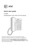
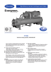
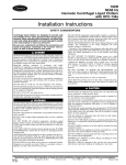
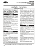
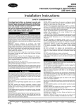
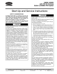
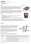
Product Data EVERGREEN® 23XRV High-Efficiency Variable Speed Screw Chiller with FOXFIRE™ Compression Technology 50/60 Hz HFC-134a 300 to 550 Nominal Tons (1055 to 1934 Nominal kW) ® Carrier’s Evergreen® 23XRV chiller is the world’s first integrated variable speed, water-cooled, screw chiller. It incorporates significant breakthroughs in water-cooled chiller technology to provide excellent reliability and achieve superior efficiencies at true operating conditions without compromising the environment. The 23XRV chiller provides: • Variable speed, positive displacement screw compressor. • Air Conditioning, Heating, and Refrigerant Institute (AHRI) certified efficiencies to 0.33 kW/ton (AHRI IPLV). • Chlorine-free HFC-134a refrigerant. • IEEE-519 compliance for harmonic distortion. • An ideal solution for constant and variable flow pumping systems. Features/Benefits Quality design and construction make the Evergreen 23XRV chillers the best choice for modern, efficient chilled water plants. Product reliability 23XRV SEISMICOMPLIANT* * Meets IBC 2006, ASCE-7-05, CBC 2007, and OSHPD seismic requirements. ® 2008 AHR EXPO INNOVATION AWARD The 23XRV chiller uses proven technology from Carrier’s existing line of Evergreen chillers along with innovations that increase reliability. The 23XRV compressors are designed for extremely high reliability. The advanced tri-rotor compressor features a balanced rotor geometry and shorter screw lengths, resulting in vastly reduced compressor bearing loads and a minimum L10 compressor bearing life in excess of 500,000 hours when operated at AHRI conditions. WINNER – Green Building Copyright 2010 Carrier Corporation Form 23XRV-3PD Features/Benefits (cont) Variable speed capacity control eliminates slide valves, their associated losses, and their potential failure modes. Component count (both rotating and total) has been minimized assuring maximum reliability under a wide range of operating conditions. High efficiency Per AHRI 550/590, chillers operate at design conditions less than one percent of the time. As a result, superior part load efficiency is required for today’s chilled water applications. The Evergreen® 23XRV screw chiller maximizes chiller efficiency by optimizing compressor operation. Electric power consumption drops dramatically when the motor speed slows. The 23XRV screw chiller delivers industry-leading integrated part load values (IPLV) in an extremely broad range of applications and climates. Environmental leader Carrier has long been committed to the environment and its sustainability. The Evergreen 23XRV screw chillers provide our customers with a highefficiency, chlorine-free, long-term solution unaffected by refrigerant phase outs. Carrier’s decision to utilize non-ozone depleting HFC-134a refrigerant provides our customers with a safe and environmentally sound product without compromising efficiency. In addition, HFC-134a was given an A1 safety rating by ASHRAE (American Society of Heating, Refrigerating and Air Conditioning Engineers), meaning that it is the safest refrigerant available. Quality design Positive displacement compression — Positive displacement compression ensures stable operation under all load conditions without the possibility of compressor surge. Superior oil management/cold condenser water operation — All Evergreen 23XRV chillers regulate oil temperature, viscosity and pressure. A patented process assures high quality oil is delivered to the compressor bearings by a positive displacement pump. Bearing lubrication is assured, allowing continuous operation with cold condenser water at all loads. Screw chillers no longer need to rely on differential system pressure to effectively lubricate the compressor. Should the 2 0.99 power factor — The Everinput power to the chiller be lost, the green 23XRV chiller can operate at up system design assures proper lubrication of the bearings during coast down. to 0.99 displacement power factor, which helps building owners avoid Small footprint — The Evergreen power factor penalties and decreases 23XRV chiller’s positive pressure electrical losses in cables and transdesign reduces the chiller size by up to 35% compared to negative-pressure formers. High power factor may also reduce KVA requirements, saving elecdesigns. Extremely high compression trical system costs on new projects or efficiencies allow for compact, high-efficiency chillers that require less freeing up electrical resources on existing systems operating near their maximechanical room floor space. mum capacity. Constant or variable evaporator Refrigerant-cooled VFD — Refrigflow — The 23XRV chiller combines erant cooling of the VFD minimizes the advantages of positive displaceVFD size and ensures proper cooling ment compression with variable speed capacity control. This process provides of the transistors for extended life. Using R-134a refrigerant instead of a chiller that reacts substantially better water also eliminates costly maintethan chillers equipped with inlet guide nance associated with the water coolvanes or slide valves. This allows for ing pump, heat exchanger and rubber easier transition when bringing additubing used with water-cooled VFDs. tional chillers on line in multiple chiller plants and eliminates any possibility of Optional seismic kit — A seismic surge, regardless of the changes in the isolation package is available to meet International Building Code and ASCE system. 7 seismic qualification requirements in Low harmonic distortion — The Evergreen 23XRV chiller will generate concurrence with ICC ES AC156 Acceptance Criteria for Seismic Qualificaless than 5% total harmonic distortion tion by Shake-Table Testing of Nonat the input to the VFD (variable structural Components and Systems. frequency drive) without the use of Hermetic motor — The Evergreen any external filters or line reactors. 23XRV chiller utilizes motors that are This assures the VFD alone cannot hermetically sealed from the machine exceed the IEEE-519 standard for room. Cooling is accomplished by distortion at the point of common spraying liquid refrigerant on the coupling. Ultra-low harmonics can motor windings. This highly efficient eliminate the need for complicated motor cooling method results in coolerharmonic system studies. running motors than could be realized Low starting current (inrush) — with air-cooled designs of the same The inrush current is limited to the type. chiller full load amps (rated load In addition, Carrier’s hermetic deamperes). No other starting means can sign eliminates: equal this level of starting current. The combination of low current and ultra • Compressor shaft seals that require low harmonics can reduce backup maintenance and increase the likeligenerator size requirements. hood of refrigerant leaks. Table of contents Page Features/Benefits . . . . . . . . . . . . . . . . . . . . . . . . . . . . . . . . . . . . . . . . . 1-4 Model Number Nomenclature . . . . . . . . . . . . . . . . . . . . . . . . . . . . . . . . . . . 4 Physical Data . . . . . . . . . . . . . . . . . . . . . . . . . . . . . . . . . . . . . . . . . . . . 5, 6 Options and Accessories . . . . . . . . . . . . . . . . . . . . . . . . . . . . . . . . . . . . . . 7 Dimensions . . . . . . . . . . . . . . . . . . . . . . . . . . . . . . . . . . . . . . . . . . . . . . . 8 Performance Data . . . . . . . . . . . . . . . . . . . . . . . . . . . . . . . . . . . . . . . . . . 9 Electrical Data . . . . . . . . . . . . . . . . . . . . . . . . . . . . . . . . . . . . . . . . . . . . . 10 Controls . . . . . . . . . . . . . . . . . . . . . . . . . . . . . . . . . . . . . . . . . . . . . . 11-14 Typical Piping and Wiring . . . . . . . . . . . . . . . . . . . . . . . . . . . . . . . . . . . . 15 Control Wiring Schematic . . . . . . . . . . . . . . . . . . . . . . . . . . . . . . . . . . . . 16 Application Data . . . . . . . . . . . . . . . . . . . . . . . . . . . . . . . . . . . . . . . . 17-23 Guide Specifications . . . . . . . . . . . . . . . . . . . . . . . . . . . . . . . . . . . . . 24-31 910 • Machine room cooling requirements associated with air-cooled motors, which dissipate heat to the mechanical room. • High noise levels common with aircooled motors, which radiate noise to the machine room and adjacent areas. • Shaft alignment problems that occur with open-drive designs during startup and operation, when equipment temperature variations cause thermal expansion. Positive pressure design — Positive pressure designs eliminate the need for costly low pressure containment devices, reducing the initial cost of the system. The Evergreen® 23XRV chiller’s positive pressure design ensures that air, moisture and other performance degrading contaminants are not sucked inside the chiller. Purge units and their associated maintenance are no longer necessary. Optional refrigerant isolation valves — The optional refrigerant isolation valves allow the refrigerant to be stored inside the chiller during shipment from the factory, minimizing start-up time. During servicing, the “in-chiller” storage reduces refrigerant loss and eliminates time-consuming transfer procedures. As a self-contained unit, the Evergreen 23XRV chiller does not require additional remote storage systems. Optional pumpdown unit — Combined with the refrigerant isolation valves listed above, the optional pumpdown unit eliminates complex connections to portable transfer systems, thereby reducing service costs. The optional pumpdown compressor meets Environmental Protection Agency’s (EPA) vacuum level requirements that mandate minimizing refrigerant emissions during service. Modular construction — The cooler, condenser, and compressor assemblies are bolted together, making Evergreen 23XRV chillers ideally suited for replacement jobs where ease of disassembly and reassembly at the jobsite are essential. Single point power — The 23XRV chiller features internal control power transformers to provide low voltage power (115 v and 24 vdc) for machine controls. Simply connecting the three input power leads to the VFD provides all unit power. Marine container shipment — The compact design allows for open-top container shipment to export destinations, ensuring quality while reducing shipping cost. Heat exchanger combinations — The Evergreen 23XRV chillers are available with a complete line of heat exchangers, ensuring the best combination of chiller components to meet project specific tonnage and efficiency requirements. One, 2 and 3-pass arrangements are available to meet a wide variety of flow conditions. Nozzlein-head and marine waterboxes are available to meet 150 psig and 300 psig piping requirements. Heat exchanger features ASME certified construction — An independent agency certifies the design, manufacture, and testing of all heat exchangers to American Society of Mechanical Engineers (ASME) standards, ensuring heat exchanger safety, reliability and long life. The ASME U-stamp is applied to the refrigerant side of the evaporator and condenser and is applied to the water side of heat exchangers when 300 psig marine water boxes are provided. High performance tubing — Carrier’s Evergreen chillers utilize advances in heat transfer technology, providing compact, high-efficiency heat exchangers. Tubing with advanced internally and externally enhanced geometry improves chiller performance by reducing overall resistance to heat transfer while reducing fouling. Cooler tube expansion — Cooler tube expansion at center support sheets prevents unwanted tube movement and vibration, thereby reducing the possibility of premature tube failure. Tube wall thickness is greater at the expansion location, support sheets, and end tube sheets in order to provide maximum strength and long tube life. Double-grooved end tube sheet holes — This design provides a more robust seal than single rolled joints, reducing the possibility of leaks between the water and refrigerant sides of the chiller. Condenser baffle — The baffle deflects hot discharge gas before it contacts condenser tubes, reducing tube vibration and wear while distributing refrigerant more evenly over the length of the vessel for improved efficiency. Closely spaced intermediate support sheets — Support sheets prevent tube sagging and vibration, thereby increasing heat exchanger life. Refrigerant filter isolation valves — These valves allow filter replacement without pumping down the chiller, reducing service time and expense. FLASC (flash subcooler) — The subcooler, located in the bottom of the condenser, increases the refrigeration effect by cooling the condensed liquid refrigerant to a lower temperature, thereby reducing compressor power consumption. AccuMeter™ system — The AccuMeter system regulates refrigerant flow according to load conditions, providing a liquid seal at all operating conditions, eliminating unintentional hot gas bypass. Microprocessor controls features Direct Digital Product Integrated control (PIC III) — Carrier’s PIC III provides unmatched flexibility and functionality. Each unit integrates directly with the Carrier Comfort Network® (CCN) system, providing a solution to controls applications. International Chiller Visual Controller (ICVC) — The ICVC provides an unparalleled ease of operation and can be configured to display English or metric values. For convenience, a single display located on the chiller VFD panel displays chiller and VFD data. The VGA 320 x 240 element LCD (liquid crystal display) features 4 menu specific softkeys. The default display offers an all-in-one glance review of key chiller operation data, simplifying the interaction between chiller and user. The display includes 4 standard languages: • English • Chinese • Japanese • Korean Other languages are available. Automatic capacity override — This function unloads the compressor whenever key safety limits are approached, increasing unit life. This 3 Features/Benefits (cont) feature also allows the machine to operate at reduced capacity, rather than shut down, when key safety limits are approached. Chilled liquid reset — Reset can be accomplished manually or automatically from the building management system. For a given capacity, reset allows operation at slower compressor speeds, saving energy when warmer chilled liquid can be used. Demand limiting — This feature limits the power draw of the chiller during peak loading conditions. When incorporated into the Carrier Comfort Network® building automation system, a red line command holds chillers at their present capacity and prevents any other chillers from starting. If a load shed signal is received, the compressors are unloaded to avoid demand charges whenever possible. Ramp loading — Ramp loading ensures smooth pulldown of liquid loop temperature and prevents a rapid increase in compressor power consumption during the pulldown period. Automated controls test — The test can be executed prior to start-up to verify that the entire control system is functioning properly. 365-day real time clock — This feature allows the operator to program a yearly schedule for each week, weekends, and holidays. Occupancy schedules — Schedules can be programmed into the controller to ensure that the chiller operates when cooling is required and remains off when not needed by the tenants or process. Extensive service menu — Unauthorized access to the service menu can be prevented through password protection. Built-in diagnostic capabilities assist in troubleshooting and recommend proper corrective action for preset alarms, resulting in greater working time. Alarm file — This file maintains the last 25 time-and date-stamped alarm messages in memory. This function reduces troubleshooting time and cost. Alert file — This file maintains the last 25 alert messages in memory. This function provides prognostic information and corrective actions that can avoid unit shutdown. Configuration data backup — Non-volatile memory provides protection during power failures and eliminates time consuming control reconfiguration. Model number nomenclature S – Special Not Used 23XRV – High Efficiency Variable Speed Screw Chiller Voltage Code 3 – 380-3-60 4 – 416-3-60 5 – 460-3-60 9 – 380/415-3-50 Cooler Size* 30-32 35-37 40-42 45-47 50-52 55-57 Drive Code AA BA BB CC Condenser Size* 30-32 35-37 40-42 45-47 50-52 55-57 Amps In† 440 520 520 608 Amps Out† 442 442 520 608 Motor Code P T Q U R V S Economizer Option E – With Economizer N – No Economizer a23-1648 *First number denotes frame size. †Maximum limits only. Additional application limits apply that may reduce these ampacities. R – Compressor Quality Assurance Certified to ISO 9001:2000 ASME ‘U’ Stamp SEISMICOMPLIANT* AHRI (Air Conditioning, Heating and Refrigeration Institute) Performance Certified * Meets IBC 2006, ASCE-7-05, CBC 2007, and OSHPD seismic requirements. 4 Physical data 23XRV COMPRESSOR AND MOTOR WEIGHTS ENGLISH MOTOR SIZE Total Compressor Weight (lb) Stator Weight (lb) 4866 441 P,Q,R,S, T,U,V SI Rotor Weight (lb) Motor Terminal Cover (lb) Compressor Weight (kg) Stator Weight (kg) Rotor Weight (kg) Motor Terminal Cover (kg) 229 46 2207 200 104 21 COMPONENT WEIGHTS FRAME 3 HEAT EXCHANGER lb kg 70 32 179 81 747 339 1650 749 700 318 542 246 COMPONENT Isolation Valves Suction Elbow Discharge Elbow/Muffler Control Center/VFD Vaporizer and Oil Sump Economizer VFD FRAME 4 HEAT EXCHANGER lb kg 70 32 237 108 747 339 1650 749 700 318 542 246 FRAME 5 HEAT EXCHANGER lb kg 115 52 232 105 747 339 1650 749 700 318 542 246 LEGEND — Variable Frequency Drive 23XRV HEAT EXCHANGER WEIGHTS ENGLISH CODE NUMBER OF TUBES Cooler Cond. 30 31 32 35 36 37 40 41 42 45 46 47 50 51 52 55 56 57 200 240 282 200 240 282 324 364 400 324 364 400 431 485 519 431 485 519 218 266 315 218 266 315 366 415 464 366 415 464 507 556 602 507 556 602 Dry Rigging Weight (lb)* Cooler Only Cond. Only 4148 4330 4522 4419 4627 4845 5008 5178 5326 5463 5659 5830 5827 6053 6196 6370 6631 6795 3617 3818 4023 4529 4758 4992 4962 5155 5347 5525 5747 5967 6013 6206 6387 6708 6930 7138 Machine Charge METRIC (SI) Dry Rigging Weight (kg)* Machine Charge Refrigerant Liquid Weight Refrigerant Liquid Weight Weight (lb) (lb) Weight (kg) (kg) Cooler Cond. Only Only With Without With Without Economizer Economizer Cooler Cond. Economizer Economizer Cooler Cond. 800 650 464 464 1877 1676 363 295 210 210 800 650 531 542 1959 1769 363 295 241 246 800 650 601 621 2046 1860 363 295 273 282 910 760 511 513 2000 2089 413 345 232 233 910 760 587 602 2094 2195 413 345 266 274 910 760 667 692 2193 2299 413 345 303 314 900 825 863 915 2675 2746 408 375 391 415 408 375 422 451 900 825 930 995 2758 2839 900 825 990 1074 2832 2932 408 375 449 487 1015 960 938 998 2882 3001 460 436 425 453 1015 960 1014 1088 2976 3108 460 436 460 494 1015 960 1083 1179 3061 3214 460 436 491 535 1250 1100 1101 1225 3182 3304 567 499 499 556 1250 1100 1192 1304 3294 3397 567 499 541 591 1250 1100 1248 1379 3364 3485 567 499 566 626 1430 1280 1201 1339 3429 3620 649 581 545 607 1430 1280 1304 1429 3556 3726 649 581 591 648 1430 1280 1369 1514 3636 3826 649 581 621 687 COND — Condenser *Rigging weights are for standard tubes of standard wall thickness (EDE and Spikefin 3, 0.025-in. [0.635 mm] wall). NOTES: 1. Cooler includes the suction elbow and 1/2 the distribution piping weight. 2. Condenser includes float valve and sump, discharge elbow, and 1/2 the distribution piping weight. 3. For special tubes, refer to the 23XRV Computer Selection Program. 4. All weights for standard 2-pass NIH (nozzle-in-head) design with victaulic grooves. 5 Physical data (cont) ADDITIONAL WEIGHTS FOR 23XRV MARINE WATERBOXES* 150 psig (1034 kPa) MARINE WATERBOXES FRAME NUMBER OF PASSES 1 and 3 2 1 and 3 2 1 and 3 2 3 4 5 ENGLISH (lb) Cooler Condenser Rigging Wgt Liquid Wgt Rigging Wgt Liquid Wgt 730 700 N/A N/A 365 350 365 350 1888 908 N/A N/A 944 452 989 452 2445 1019 N/A N/A 1223 510 1195 499 SI (kg) Cooler Condenser Rigging Wgt Liquid Wgt Rigging Wgt Liquid Wgt 331 318 N/A N/A 166 159 166 159 856 412 N/A N/A 428 205 449 205 1109 462 N/A N/A 555 231 542 226 300 psig (2068 kPa) MARINE WATERBOXES FRAME 3 4 5 NUMBER OF PASSES 1 and 3 2 1 and 3 2 1 and 3 2 ENGLISH (lb) Cooler Condenser Rigging Wgt Liquid Wgt Rigging Wgt Liquid Wgt 860 700 N/A N/A 430 350 430 350 2162 908 N/A N/A 1552 393 1641 393 2655 1019 N/A N/A 1965 439 1909 418 SI (kg) Cooler Condenser Rigging Wgt Liquid Wgt Rigging Wgt Liquid Wgt 390 318 N/A N/A 195 159 195 159 981 412 N/A N/A 704 178 744 178 1204 462 N/A N/A 891 199 866 190 *Add to cooler and condenser weights for total weights. Cooler and condenser weights may be found in the 23XRV Heat Exchanger Weights table on page 5. The first digit of the heat exchanger code (first column) is the heat exchanger frame size. 23XRV WATERBOX COVER WEIGHTS — ENGLISH (lb) FRAMES 3, 4, AND 5 WATERBOX DESCRIPTION NIH,1 pass Cover 150 psig NIH,2 pass Cover 150 psig NIH,3 pass Cover 150 psig NIH Plain End, 150 psig MWB End Cover, 150 psig* NIH,1 pass Cover 300 psig NIH,2 pass Cover 300 psig NIH,3 pass Cover 300 psig NIH Plain End, 300 psig MWB End Cover, 300 psig* COOLER Frame 4 Frame 3 Frame 5 Frame 3 CONDENSER Frame 4 Frame 5 Victaulic Nozzles Flanged Victaulic Nozzles Flanged Victaulic Nozzles Flanged Victaulic Nozzles Flanged Victaulic Nozzles Flanged Victaulic Nozzles Flanged 282 287 294 243 243/315 411 411 433 294 445/619 318 340 310 243 243/315 486 518 468 294 445/619 148 202 472 138 138/314 633 626 660 522 522/522 185 256 488 138 138/314 709 733 694 522 522/522 168 222 617 154 154/390 764 760 795 658 658/658 229 275 634 154 154/390 840 867 830 658 658/658 282 287 294 225 225/234 411 411 433 270 359/474 318 340 310 225 225/234 486 518 468 270 359/474 148 191 503 138 138/314 633 622 655 522 658/658 185 245 519 138 138/314 709 729 689 522 658/658 168 224 628 154 154/390 764 727 785 658 658/658 229 298 655 154 154/390 840 878 838 658 658/658 LEGEND NIH — Nozzle-in-Head MWB — Marine Waterbox *Nozzle end weight/return end weight. NOTE: Weight for NIH 2-pass cover, 150 psig (1034 kPa), is included in the heat exchanger weights shown on page 5. 23XRV WATERBOX COVER WEIGHTS — SI (kg) FRAMES 3, 4, AND 5 WATERBOX DESCRIPTION NIH,1 pass Cover 1034 kPa NIH,2 pass Cover 1034 kPa NIH,3 pass Cover 1034 kPa NIH Plain End, 1034 kPa MWB End Cover, 2068 kPa* NIH,1 pass Cover 2068 kPa NIH,2 pass Cover 2068 kPa NIH,3 pass Cover 2068 kPa NIH Plain End, 2068 kPa MWB End Cover, 2068 kPa* LEGEND NIH — Nozzle-in-Head MWB — Marine Waterbox 6 Frame 3 COOLER Frame 4 Frame 5 Frame 3 CONDENSER Frame 4 Frame 5 Victaulic Nozzles Flanged Victaulic Nozzles Flanged Victaulic Nozzles Flanged Victaulic Nozzles Flanged Victaulic Nozzles Flanged Victaulic Nozzles Flanged 128 130 133 110 110/143 186 186 196 132 202/281 144 154 141 110 110/143 220 235 212 132 202/281 67 92 214 63 63/142 287 284 299 237 237/237 84 116 221 63 63/142 322 332 315 237 237/237 76 101 280 70 70/177 347 344 361 298 298/298 104 125 288 70 70/177 381 393 376 298 298/298 128 130 133 102 102/106 186 186 196 122 163/215 144 154 141 102 102/106 220 235 212 122 163/215 67 87 228 63 63/142 287 282 297 237 298/298 84 111 235 63 63/142 322 331 313 237 298/298 76 102 285 70 70/177 347 330 356 298 298/298 104 135 297 70 70/177 381 398 380 298 298/298 *Nozzle end weight/return end weight. NOTE: Weight for NIH 2-pass cover, 150 psig (1034 kPa), is included in the heat exchanger weights shown on page 5. Options and accessories ITEM .028 or .035 in. (0.711 or 0.889 mm) Internally/Externally Enhanced Copper Tubing — Cooler/Condenser .028 or .035 in. (0.711 or 0.889 mm) Internally/Externally Enhanced Cupronickel Tubing — Condenser .028 or .035 in. (0.711 or 0.889 mm) Smooth Bore/Externally Enhanced Copper Tubing — Cooler/Condenser .028 or .035 in. (0.711 or 0.889 mm) Smooth Bore/Externally Enhanced Cupronickel Tubing — Condenser Flanged Cooler and/or Condenser Waterbox Nozzles** Hinged Waterboxes Marine Waterboxes, 150 psig (1034 kPa)†† Marine Waterboxes, 300 psig (2068 kPa)†† Nozzle-in Head Waterbox, 300 psig (2068 kPa) One, 2, or 3 Pass Cooler or Condenser Waterside Construction Seismic Kit Zinc Anodes 100K AIC (Amp Interrupt Capacity) High Interrupt Circuit Breaker with Shunt Trip Analog Voltmeter and Ammeter with 3 Phase Selector Switch BACnet*** Communications LonWorks††† Carrier Translator Sensor Package Refrigerant Isolation Valves Separate Storage Tank and Pumpout Unit Shipped Factory Charged with Refrigerant Stand-Alone Pumpout Unit Unit-Mounted Pumpout Unit Hot Gas Bypass Soleplate Package Spring Isolator Kit Acoustical Sound Insulation Kit Full Cold Surface Thermal Insulation (Except Waterbox Covers) Customer Factory Performance Testing Export Crating Extended Warranty (North American Operations [NAO] only) Service Contract *Factory-installed. †Field-installed. **Standard waterbox nozzles are victaulic type. Flanged nozzles are available as an option with either nozzle-in-head type waterboxes or marine waterboxes. 910 OPTION* ACCESSORY† X X X X X X X X X X X X X X X X X X X X X X X X X X X X X X X ††Optional marine waterboxes available for 23XRV heat exchanger frames 3-5 only. Standard waterboxes for 23XRV are nozzle-in-head type, 150 psig (1034 kPa). ***Sponsored by ASHRAE (American Society of Heating, Refrigerating, and Air Conditioning Engineers). †††Registered trademark of Echelon Corporation. 7 Dimensions 23XRV DIMENSIONS TUBE REMOVAL SPACE FOR EITHER END SIZES 30-32, 40-42 50-52 14’-3” (4343 mm) SIZES 35-37, 45-47 55-57 14’-0” (4267 mm) MOTOR SERVICE CLEARANCE 1’-10” (559 mm) FRAME R COMPRESSOR 3’-0” (915mm) RECOMMENDED OVERHEAD SERVICE CLEARANCE a23-1646 C 2’ MIN (610 mm) B (WIDEST POINT) A 4’ MIN (1219 mm) SERVICE AREA 4’-10” MIN (1475 mm) 23XRV DIMENSIONS (NOZZLE-IN-HEAD WATERBOX) HEAT EXCHANGER SIZE 30 to 32 1 Pass ft-in. 14- 31/4 35 to 37 15-113/4 A (Length, with Nozzle-in-Head Waterbox) 2-Pass* 3 Pass mm ft-in. mm ft-in. mm 4350 13- 81/4 4172 14- 31/4 4350 4870 15- 43/4 31/ 4693 15-113/4 4870 B (Width) C (Height) ft-in. 6- 4 mm 1930 ft-in. 7- 25/8 mm 2200 6- 4 1930 7- 25/8 2200 81/2 2045 7- 61/2 2299 40 to 42 14- 9 4496 14- 8 4347 14- 6 4420 6- 45 to 47 16- 51/2 5017 15-115/8 4867 16- 21/2 4940 6- 81/2 2045 7- 61/2 2299 50 to 52 14-10 4521 14- 41/2 4382 14- 61/2 4432 6-113/4 2127 7- 63/4 2305 55 to 57 16- 61/2 5042 16- 1 4902 16- 3 4953 6-113/4 2127 7- 63/4 2305 23XRV DIMENSIONS (MARINE WATERBOX) HEAT EXCHANGER SIZE 30 to 32 A (Length, Marine Waterbox) 2-Pass* 1 or 3 Pass† ft-in. mm ft-in. 14- 9 4496 16- 43/4 mm 4997 C (Height) ft-in. 6- 93/8 mm 2067 35 to 37 16- 51/2 5017 18- 11/4 5518 6- 93/8 2067 40 to 42 15- 23/4 4642 16- 31/4 5086 6- 93/4 2076 45 to 47 16-113/4 5163 18- 43/4 5607 6- 93/4 2076 50 to 52 15- 31/2 4661 16- 81/2 5093 7- 1 2159 55 to 57 17- 0 5182 18- 5 5613 7- 1 2159 *Assumes both cooler and condenser nozzles on same end of chiller. †1 or 3 pass length applies if cooler is a 1 or 3 pass design. NOTES: 1. Service access should be provided per American Society of Heating, Refrigerating, and Air Conditioning Engineers (ASHRAE) 15, latest edition, National Fire Protection Association (NFPA) 70, and local safety code. 2. Allow at least 3 ft (915 mm) overhead clearance for service rigging for the compressor. 8 B (Width) See unit certified drawings 3. Certified drawings available upon request. 4. Marine waterboxes may add 6 in. (152 mm), to the width of the machine. See certified drawings for details. 5. ‘A’ length and ‘B’ width dimensions shown are for standard 150 psig (1034 kPa) design and victaulic connections. The 300 psig (2068 kPa) design and/or flanges will add length. See certified drawings. 6. Dished head waterbox covers not available for the 3-pass design. Performance data NOZZLE SIZE NOZZLE SIZE (in.) (Nominal Pipe Size) FRAME SIZE 3 4 5 1-Pass 10 10 10 Cooler 2-Pass 8 8 8 3-Pass 6 6 6 1-Pass 10 10 10 Condenser 2-Pass 8 8 10 3-Pass 6 6 8 23XRV HEAT EXCHANGER MIN/MAX FLOW RATES* ENGLISH (GPM) COOLER Frame Size 30 31 32 3 35 36 37 40 41 42 4 45 46 47 50 51 52 5 55 56 57 1 PASS Min Max 611 2,444 733 2,933 855 3,422 611 2,444 733 2,933 855 3,422 989 3,959 1112 4,448 1222 4,888 989 3,959 1112 4,448 1222 4,888 1316 5,267 1482 5,927 1586 6,343 1316 5,267 1482 5,927 1586 6,343 2 PASS Min Max 305 1222 367 1466 428 1710 305 1222 367 1466 428 1710 495 1979 556 2224 611 2444 495 1979 556 2224 611 2444 658 2634 741 2964 793 3171 658 2634 741 2964 793 3171 3 PASS Min Max 204 815 244 978 285 1141 204 815 244 978 285 1141 330 1320 371 1482 407 1775 330 1320 371 1482 407 1775 439 1756 494 1976 529 2114 439 1756 494 1976 529 2114 CONDENSER Frame Size 30 31 32 3 35 36 37 40 41 42 4 45 46 47 50 51 52 5 55 56 57 1 PASS Min Max 646 2,582 791 3,162 932 3,731 646 2,582 791 3,162 932 3,731 1096 4,383 1235 4,940 1371 5,485 1096 4,383 1235 4,940 1371 5,485 1507 6,029 1646 6,586 1783 7,131 1507 6,029 1646 6,586 1783 7,131 2 PASS Min Max 323 1291 395 1581 466 1865 323 1291 395 1581 466 1865 548 2192 618 2470 686 2743 548 2192 618 2470 686 2743 754 3015 823 3293 891 3565 754 3015 823 3293 891 3565 3 PASS Min Max 215 861 263 1054 311 1244 215 861 263 1051 311 1244 365 1461 412 1647 457 1828 365 1461 412 1647 457 1828 502 2010 549 2195 594 2377 502 2010 549 2195 594 2377 *Flow rates based on standard tubes in the cooler and condenser. Minimum flow based on tube velocity of 3 ft/sec (0.91 m/sec); maximum flow based on tube velocity of 12 ft/sec (3.66 m/sec). Consult the factory if variable primary flow. SI (L/s) COOLER Frame Size 30 31 32 3 35 36 37 40 41 42 4 45 46 47 50 51 52 5 55 56 57 1 PASS Min Max 38 154 46 185 54 215 38 154 46 185 54 215 62 249 70 281 77 307 62 249 70 281 77 307 83 332 93 374 100 400 83 332 93 374 100 400 2 PASS Min Max 19 77 23 92 27 108 19 77 23 92 27 108 31 125 35 140 38 154 31 125 35 140 38 154 42 166 47 187 50 200 42 166 47 187 50 200 3 PASS Min Max 13 51 15 62 18 72 13 51 15 62 18 72 21 83 23 93 26 112 21 93 23 93 26 112 28 111 31 125 33 133 28 111 31 125 33 133 CONDENSER Frame Size 30 31 32 3 35 36 37 40 41 42 4 45 46 47 50 51 52 5 55 56 57 1 PASS Min Max 41 163 50 199 59 235 41 163 50 199 59 235 69 277 78 312 86 346 69 277 78 312 86 346 95 380 104 416 112 450 95 380 104 416 112 450 2 PASS Min Max 20 81 25 100 29 118 20 81 25 100 29 118 35 138 39 156 43 173 35 138 39 156 43 173 48 190 52 208 56 225 48 190 52 208 56 225 3 PASS Min Max 14 54 17 67 20 79 14 54 17 67 20 79 23 92 26 104 29 115 23 92 26 104 29 115 32 127 35 138 37 150 32 127 35 138 37 150 *Flow rates based on standard tubes in the cooler and condenser. Minimum flow based on tube velocity of 3 ft/sec (0.91 m/sec); maximum flow based on tube velocity of 12 ft/sec (3.66 m/sec). Consult the factory if variable primary flow. 9 Electrical data VFD FRAME SIZES FRAME SIZE AA BA BB CC MAX INPUT CURRENT* 440 520 520 608 MAX OUTPUT CURRENT* 442 442 520 608 *Maximum limits only. Additional application limits apply that will reduce these ampacities. AUXILIARY RATINGS* VOLTAGE MAXIMUM PROTECTIVE DEVICE SIZE (AMPS) WATTS Controls, Oil Pump And Heater Circuit† Oil Pump Oil Sump Heater 115 115 115 15 1.48 4.35 — 130 500 Oil Vaporizer Heater Circuit† Oil Vaporizer Heater 115 115 15 13 — 1500 ITEM *Factory wired to VFD. †Minimum circuit ampacity of 15 amps. 10 Controls Microprocessor controls Microprocessor controls provide the safety, interlock, capacity control, indications and accessibility necessary to operate the chiller in a safe and efficient manner. Control system The microprocessor control on each Carrier chiller is factory-mounted, factory-wired, and factory-tested to ensure machine protection and efficient capacity control. In addition, the program logic ensures proper starting, stopping, and recycling of the chiller and provides a communication link to the Carrier Comfort Network® (CCN) system. Features Control system • Component test and diagnostic check • Programmable recycle allows chiller to recycle at optimum loads for decreased operating costs • Menu-driven keypad interface for status display, set point control, and system configuration • CCN system compatible • Primary and secondary status messages • Individual start