1
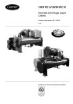
High-Efficiency Hermetic Centrifugal Liquid Chillers
Quality and Environment
Management System
Approval
19XR/19XRV
Nominal cooling capacity 1000-5300 kW
■■
■■
■■
■■
■■
The Carrier 19XR/19XRV centrifugal chillers provide
exceptional value by achieving energy efficiency levels as
high as 6.8 (EER) utilising proven technology designed
specifically for chlorine-free refrigerants:
Unique concept of the hermetic compressor:
-- Single-stage aerodynamic impeller
-- Tunnel diffusers, based on aircraft engine technology
-- Motor cooled by refrigerant gas injection
Possibility to control the compressors using a variablefrequency drive (19XRV) to maximise machine energy
efficiency.
Use of high-efficiency evaporator and condenser tubes
Expansion sub-cooler integrated into the condenser
Patented float valve technology for optimised sub-cooling
and refrigerant level in the evaporator
Features
These advantages, together with the modularity of the units
and their efficiency, economical operation and dimensional
constraints allow the use of the Carrier 19XR/19XRV
centrifugal chillers in any high-capacity water cooling
applications.
The units also offer a wide choice of possible combinations to
ensure optimised matching of the compressor performance
to the specific requirements.
■■ Single-stage hermetic compressor
This design:
-- increases product reliability by eliminating the additional
moving parts associated with multiple stage machines,
such as additional guide vanes and complex economizers.
-- eliminates refrigerant leaks from the compressor/motor
transmission joints in open-drive compressors.
■■ HFC-134a - an environmentally-sound solution
The 19XR/19XRV chillers use chlorine-free HFC-134a
refrigerant with zero ozone-depletion potential, still the
refrigerant of choice for automotive and appliance
manufacturers.
■■ Mix-match capabilities
A complete line of compressors and heat exchangers is
available for these chillers, optimising the machine component combination regardless of capacity, lift, and efficiency
specifications.
■■ Heat exchangers feature:
European pressure vessel code certified construction,
ensuring maximum heat exchanger safety, reliability and
long life.
■■ Compressor with variable-frequency drive (VFD)
19XRV chillers are equipped with a compressor variablefrequency system. By changing the compressor operating
mode this system considerably reduces power consumption
based on the motor rotational speed.
In addition, the variable-frequency drive control box is
cooled by refrigerant minimising its size and ensuring
optimal component cooling for an extended operating life.
This concept makes water cooling unnecessary and eliminates the associated maintenance cost and water pump
power consumption.
■■ Aerodynamically-contoured impellers
Impellers that utilize high back sweep main blades with
low-profile intermediate splitter blades are aerodynamically contoured to improve compressor full-load and
part-load operating efficiency.
Easy installation
■■ Chilled-water reset
■■
■■
■■
■■
■■ Modular construction
The cooler, condenser, and compressor assemblies are
completely bolted together, making the 19XR/19XRV
chillers ideally suited for replacement projects where ease
of disassembly and reassembly at the jobsite are essential.
■■ Water piping
The unit has quick and easy piping: the standard unit
includes nozzle-in head water boxes with Victaulic grooves
to allow for use of Victaulic couplings. Flanges are available
as an option.
■■ Optional unit-mounted electronic starter
Carrier’s unit-mounted electronic starter is only available
as a low-voltage version and provides a single point power
connection, reducing machine installation time and expense.
■■ Quick start-up
The 19XR/XRV unit manufacturing site uses a quality
management process that is certified to ISO 9001. All units
undergo factory checks to ensure easy and reliable start-up.
Compressors are run-tested to ensure proper operation of
all compressor systems, including oil management, vibration,
electrical, power transmission, and compression.
■■
■■
■■
■■
Power supply and controls
1 - Control boxes
■■ Serviceability and convenience have been “designed-in”,
for example:
-- Control transformer is fitted as standard
-- Single-point mains power connection if unit-mounted
■■
starter is supplied
-- All components are mounted using connectors to facilitate
fast servicing and replacement
-- Components are labelled and numbered according to
wiring diagrams
-- IP 23C protection on the whole unit
■■
2 - Controls system
■■ Numerical product-integrated control (PIC)
The Carrier numerical product-integrated PIC control
provides unmatched flexibility and functionality. Each unit
integrates directly with an installation control system (using
several communication protocols) that offers a global
system solution.
■■ Human interface (ICVC)
The ICVC (Interface Chiller Visual Control), that can be
configured to display units in Imperial or metric, provides
unparalleled ease of operation. A 16-line by 40-character
LCD (Liquid Crystal Display) features four menu-specific
soft keys. Default display offers easy, quick display of key
chiller operation data, simplifying the interaction between
machine and user.
Local languages are available upon request.
2
Reset can be accomplished manually or automatically from
the building management system. Reset saves energy when
warmer chilled water can be utilized.
Demand limiting
This function limits the power draw of the chiller during
peak loading conditions. When incorporated into the
Carrier Comfort Network building automation system, a
red line command will hold chillers at their present capacity
and prevent any other chillers from starting. If a load shed
signal is received, the compressors are unloaded to avoid
high demand charges whenever possible.
Ramp loading
Ramp loading ensures a smooth pulldown of water loop
temperature and prevents a rapid increase in compressor
power consumption during the pulldown period.
Automated controls test
The test can be easily executed prior to start-up to verify
that the entire control system is functioning properly.
365-day real time clock
This feature allows for the operator to programme a
yearly schedule for each week, weekends, and holidays.
Occupancy schedules
Schedules can be programmed into the controller to ensure
that the chiller only operates when cooling is required.
Extensive service menu
Unauthorized access to the service menu can be passwordprotected. Built-in diagnostic capabilities assist in troubleshooting and recommend proper corrective action for
preset alarms, resulting in less down time.
Battery backup
Battery backup provides protection during power failures
and eliminates time consuming control reconfiguration.
Encapsulated circuit boards are designed, built and tested
in-house. Each board meets Carrier’s stringent quality
standards for superior reliability compared to open board
designs.
Other control features include:
Display of over 125 operating, status, and diagnostic
messages for improved user interface.
Examples:
-- Monitoring of over 100 functions and conditions to
protect the chiller from abnormal conditions.
-- Modular plug-in design, reducing wiring requirements
and providing easy installation.
-- Low-voltage (24 V ac) design, providing the ultimate
assurance of personal safety and control integrity.
Microprocessor-controlled oil heater
The heater prevents excessive absorption of refrigerant into
the oil during compressor shutdown, ensuring a plentiful
supply of undiluted lubrication oil in the oil sump.
Safeties
Unit is automatically shut down when any of the following
conditions occur:
-- Motor overcurrent
-- Over voltage*
-- Under voltage*
-- Single cycle dropout*
-- Bearing oil high temperature
-- Low evaporator refrigerant temperature
-- High condenser pressure
-- High motor temperature
-- High compressor discharge temperature
-- Low oil pressure
-- Prolonged surge
-- Loss of cooler water flow
-- Loss of condenser water flow
-- Starter fault
Each of these protective limits shall require manual reset
and cause an alarm message to be displayed on the LCD
screen, informing the operator of the shutdown cause.
* Do not require manual reset or cause an alarm if auto-restart after power failure is enabled.
■■ Alarm file
This file maintains the last 25 time- and date-stamped
alarm and alter messages in memory; this function reduces
troubleshooting time and cost.
■■ Overrides
The control system detects conditions which approach
protective limits and takes self-corrective action prior to
an alarm occurring.
The system automatically reduces chiller capacity when
any of the following parameters are outside their normal
operating range:
-- High condenser pressure
-- High motor temperature
-- Low evaporator refrigerant temperature
-- High motor current
During the capacity override period, a pre-alarm (alert)
message is displayed, informing the operator which condition is causing the capacity override. Once the condition is
again within acceptable limits, the override condition is
terminated and the chiller reverts to normal chiller water
control.
During either condition, if the protective limit is reached,
the chiller shuts down and a message is displayed informing
the operator which condition has caused the shutdown
and alarm. This function increases unit life.
Capacity control
■■ On the19XR base units capacity control is by means of
variable inlet guide vanes located at the impeller inlet. Load
modulation is from 100% to 15% of compressor full load
under nominal ARI conditions without the use of hot gas
bypass. The guide vanes are precisely positioned by a PID
(proportional-integral-derivative) control algorithm to
ensure precise and quick control of desired chilled-water
temperature without hunting or overshooting the set point.
If the machine includes a factory-installed variable-frequency
drive (19XRV), the compressor speed is regulated by the
control of the voltage-frequency values, applied to the
motor. The voltage applied, generated by pulse width
modulation, is proportional to the frequency.
The calculation of the water temperature parameter
deviation measured results in an adjustment of the machine
capacity through a simultaneous and coordinated action
on guide vane opening and compressor speed.
Simple to service
■■ Mechanically cleanable cooler and condenser.
■■ The machine concept allows the refrigerant to be stored
inside the chiller during servicing, reducing refrigerant loss
and eliminating time-consuming transfer procedures.
■■ Easy-access suction and discharge pressure and temperature
information using enhanced display module.
3
Refrigeration cycle of the 19XR/19XRV units
Suction
Motor and oil cooling
The compressor continuously draws refrigerant vapour
from the evaporator at a rate set by the amount of guide
vane opening or the compressor rotation speed.
FLASC (flash subcooler)
After the condensing phase the liquid refrigerant passes
through the orifices into the FLASC chamber (flash
subcooler - see figure below).
Passing over these orifices a part of the liquid refrigerant
flashes to vapour. By coming into contact with the
entering condenser water tubes (colder) this vapour is
recondensed and the liquid refrigerant is collected in a
chamber where a float valve forms a liquid seal to prevent
the FLASC chamber vapour from entering the evaporator.
The motor and the lubricating oil are cooled by liquid
refrigerant taken from the bottom of the condenser vessel
(at the level of the float chamber – see figure below). Flow
of refrigerant is maintained by the pressure differential that
exists due to compressor operation. The flow is split between
motor cooling and oil cooling systems..
If the machine includes a factory-installed variable-frequency
drive (19XRV), the motor and oil cooling system is the
same as for the base machines. In this case the liquid
refrigerant used for the motor and oil cooler also supplies
a cooling heat exchanger in the variable-frequency drive
cabinet.
This device allows subcooling of the liquid refrigerant
entering the evaporator, resulting in an enthalpy gain and
improved unit energy efficiency.
19XR refrigeration cycle
1.
2.
3.
4.
5.
6.
7.
8.
9.
10.
11.
12.
4
FLASC chamber
Condenser water
Condenser
Condenser isolation valve
Transmission
Diffuser
Guide vane motor
Motor
Guide vanes
Impeller
Compressor
19XR: Back pressure orifice
19XRV: Coooling line shut-off valve
13.
14.
15.
16.
17.
18.
19.
20.
21.
22.
23.
24.
Oil cooling
Oil filter
Oil pump
Stator
Rotor
Motor cooling isolation valve
Float valve chamber
Filter drier
Orificed fitting
Moisture/flow indicator
Orificed fitting
Thermostatic expansion valves (TXV)
- two TXVs for 19XRV units
19XRV refrigeration cycle
25.
26.
27.
28.
29.
30.
31.
32.
33.
34.
35.
Distribution pipe
Evaporator isolation valve
Evaporator
Chilled water
Refrigerant liquid
Refrigerant vapour
Refrigerant liquid/vapour
Oil*
Cooling line shut-off valve*
Variable-frequency drive cooling heat exchanger*
Variable-frequency drive cooling control solenoid valve*
* For 19XRV units only
Model number nomenclature
Service number: 19XR_50 52 4V6 LFH 52
Unit designation
19XR or 19XRV
Motor voltage code
Model: 19XR 50 52 --- 001--EE--
Unit designation
19XR / 19XV
Evaporator size
- 6 sizes
- 3 lengths
Motor efficiency code
S: standard
H: high efficiency
Evaporator size
- 6 sizes
- 3 lengths
Condenser size
- 6 sizes
- 3 lengths
Motor code
Condenser size
- 6 sizes
- 3 lengths
Unit produced in Montuel
Chronological number
Compressor code
4 sizes (2-3-4-5)
Options and accessories
Options
IP54 protection for control box
Tropicalisation
No.
20A
22
Description
Control boxes with increased leak tightness
Heating system controlled and inside the control box
Unit equipped with soft starter
Unit with star/delta starting
Unit with separate variable-frequency drive
25
25A
25F
Hot gas bypass
29
Unit supplied in foursections
51A
Unit with aluminium protection jacket for
evaporator and compressor
External refrigerant level for the evaporator
88A
Evaporator with three passes
100A
Electronic starter integrated with the control
Integrated star/delta starter connection
Unit with control box interface for wiring with separate variablefrequency drive + PICII control
Cooling line between the high-pressure discharge side and the
evaporator, equipped with a motorised butterfly valve
Unit supplied in four sections (compressor/piping + control box +
secondary components/evaporator/condenser
Additional aluminium jacket on the evaporator shell and the
water boxes, on the motor and the compressor suction elbow
Additional external refrigerant level on the evaporator with
shut-off valves
Evaporator with three heat exchange passes.
Evaporator with one pass
100C
Condenser with three passes
102A
Condenser with one pass
102C
Evaporator with 21 bar water-side pressure
104
Condenser with 21 bar water-side pressure
104A
Machine equipped with a transfer unit
CCN-JBus gateway
110
148
Unit with heat exchangers in accordance
with Swiss code
Unit equipped with flanges and counterflanges on evaporator and condenser
Unit supplied with anti-vibration platform
197
Unit supplied with spring isolation kit
261
Accessories
CCN JBus gateway
Separate transfer unit
800-litre storage tank only
1500-litre storage tank only
800-litre storage tank with transfer unit
1500-litre storage tank with transfer unit
Anti-vibration platform
Spring isolation kits
97A
259
260
Advantages
Increased protection of control boxes
Prevents condensation inside the control
box
More efficient compressor start-up control
Adaptation to the customer power network
More effient, especially at part load
Hot gas injection into the evaporator for
optimised operation
Adaptation to the customer installation
requirements
Aesthetics/maintenance
Reading of the evaporator refrigerant level
Adaptation to customer installation
requirements
Evaporator with one heat exchange pass.
Adaptation to customer installation
requirements
Condenser with three heat exchange passes.
Adaptation to customer installation
requirements
Condenser with one heat exchange pass.
Adaptation to customer installation
requirements
Evaporator with 21-bar NiH water box
Adaptation to customer installation
requirements
Condenser with 21-bar NiH water box
Adaptation to customer installation
requirements
Unit-mounted transfer unit
Ease-of-maintenance and service
Two-way communication board according to JBus protocol
Connection facilitated by communication
bus to a BMS system
Unit with PED heat exchangers in accordance with special Swiss Adaptation to the certification requirements
code
Additional flanges and counter-flanges on the heat exchanger
Adaptation to the customer installation
water box inlets/outlets for customer system connections
requirements
Anti-vibration platform for installation on each heat exchanger
Mechanical isolation
foot (accessory in part)
Spring isolation kit for each heat exchanger foot with level control Mechanical isolation
screw (supplied as accessory)
Description
Advantages
See option 148
See option 148
Separate refrigerant charge transfer unit
Ease-of-maintenance and service
800-litre refrigerant storage tank
Ease-of-maintenance and service
1500-litre refrigerant storage tank
Ease-of-maintenance and service
800-litre refrigerant storage tank with transfer unit and associated Ease-of-maintenance and service
control box
1500-litre refrigerant storage tank with transfer unit and associated Ease-of-maintenance and service
control box
See option 260
See option 260
See option 261
See option 261
5
Physical data, 19XR/19XRV units
Unit operating weight
19XR size
Operating weight*
With starter (option 25)
Without starter**
19XR size
Operating weight*
With starter (option 25)
Without starter**
3030
3232
3535
3737
4040
4242
4545
4747
5050
5252
5555
5757
kg
kg
7300
7300
6060
7700
7700
6262
7800
7800
6565
8300
8300
6767
9000
9000
7070
9500
9500
7272
9800
9800
7575
10400
10400
7777
11400
11190
8080
12000
11790
8282
12300
12090
8585
12900
12690
8787
kg
kg
12600
12390
13400
13190
13700
13490
14200
13990
20510
20300
21610
21400
21600
21390
22900
22690
23655
23500
24805
24650
24955
24800
25955
25800
4242
10050
7272
22620
4545
10350
7575
22610
4747
10950
7777
23910
5050
11930
8080
24625
5252
12530
8282
25775
5555
12830
8585
25925
5757
13430
8787
26925
* Weights given for information only. For more details please refer to the dimensional drawings.
** Standard unit with control box interface.
19XRV size**
Operating weight*
19XRV size**
Operating weight*
kg
kg
3030
7850
6060
13100
3232
8250
6262
13900
3535
8350
6565
14200
3737
8850
6767
14700
4040
9550
7070
21520
* Weights given for information only. For more details please refer to the dimensional drawings.
** With variable-frequency drive.
1219 mm
915 mm
Dimensions/clearances, 19XR/XRV units
1.
2.
Motor service space
Recommended clearance above the machine
Clearances required
D. Clearance area for heat exchanger tubes
E. Clearance for float valve, variable depending on the unit height
- see rear view, figure ”19XR Machine components” - item No. 28
on the next page.
NOTE: Non-certified drawings. Refer to the certified dimensional
drawings supplied with the unit or available on request, when designing
an installation.
610
362
mm
Note for 19XRV units: The width (B) and height (C) dimensions may
differ for units with variable-freqency drive. Please refer to the
dimensional drawings supplied with the machine.
mm
Dimensions (± 10 mm)
A (length, with nozzle-in-head water-box)
19XR heat
exchanger size
2 pass*
1 or 3 pass**
30 to 32
4230
4380
35 to 37
4754
4904
40 to 42
4230
4380
45 to 47
4754
4904
50 to 52
4230
4380
55 to 57
4754
4904
60 to 62
4230
4380
65 to 67
4754
4904
70 to 72
4919
5104
75 to 77
5525
5710
80 to 82
4919
5104
85 to 87
5525
5710
B (Width except 19XRV)
C (height)***
D
E****
1670
1670
1880
1880
2054
2054
2124
2124
2530
2530
2530
2530
2127
2127
2294
2294
2781
2780
2879
2878
3276
3276
3343
3343
3747
4278
3747
4278
3754
4278
3754
4280
4278
4884
4278
4884
250
250
250
250
250
250
250
250
460
460
460
460
* Assumes that both cooler and condenser nozzles are on the same end of the chiller.
** One- or three-pass length applies if either (or both) cooler or condenser is a 1 or 3 pass design.
*** Sizes < 50-52: maximum height given for units with starter cabinet.
Sizes ≥ 50-52 and above: maximum height given for units with high-voltage terminal box.
For more details see dimensional drawings for each unit.
**** Clearance for float valve is variable, depending on the unit height - see chapter "19XR Machine components” - item No. 28.
Nominal diameter - water inlet/outlet size (inches)
Evaporator
19XR heat
exchanger size
1 pass
2 pass
3
10
8
4
10
8
5
10
8
6
10
10
7
14
12
8
14
14
NOTES
1. Service clearance must comply with local regulations.
2. Certified drawings available upon request.
6
3 pass
6
6
6
8
10
12
Condenser
1 pass
10
10
10
10
14
14
2 pass
8
8
10
10
12
14
3 pass
6
6
8
8
12
12
19XR/XRV Machine components
Front view
1
3
Rear view
2
8
15
18
16
19
17
4
32
20
5
14
6
21
13 12
11
31
10
9
1.
2.
3.
4.
5.
6.
7.
8.
9.
10.
11.
12.
13.
14.
15.
16.
17.
30
7
29
Guide vane actuator
Suction elbow
Compressor
Cooler valve*
Cooler pressure transducer
Condenser in/out temperature thermistors
Cooler in/out temperature thermistors
Machine identification nameplate (situated on the starter cabinet side) - see
right-hand figure 'Rear view'
Refrigerant charging valve
Typical flange connections
Oil drain valve
Oil level sight glass
Refrigerant oil cooler (hidden)
Branch circuit control box
Condenser relief valve*
Circuit breaker/disconnect switch
ICVC
28
27
26 25
24 23
22
18.
19.
20.
21.
22.
23.
24.
25.
26.
27.
28.
29.
30.
31.
32.
Unit-mounted starter (19XR) or variable-frequency drive (19XRV)
Motor sight glass
Cooler return-end waterbox cover
Cooler nameplate
Condenser nameplate
Waterbox drain port
Condenser return-end waterbox cover
Refrigerant moisture/flow indicator
Refrigerant filter/drier
Liquid line isolation valve (optional)
Linear float valve chamber
Vessel take-apart connector
Discharge isolation valve (optional)
Pumpout valve
Condenser pressure transducer
*
One relief valve is standard. The optional dual relief valves include change-over
for each heat exchanger.
Compressor cut-away view
1
1
2
3
4
5
6
7
8
9
10
11
12
13
14
15
16
2
3
4
13
12
5
6
Motor stator
Motor rotor
Motor shaft journal bearings
Low-speed bull gear
High-speed shaft thrust bearing
High-speed shaft journal bearing
Variable inlet guide vanes
Impeller shroud
Impeller
Pipe diffuser
High-speed pinion gear
Oil heater
High speed shaft journal bearing
Oil pump motor
Oil filter
Oil filter cover
16
15
14
11
10
9
8
7
7
Electrical data, 19XR/XRV units
Standard voltages for 50 Hz units
Nominal voltage, V
400
690
3000
3300
6300
11000
Operating range, V
380 to 415
656 to 716
2900 to 3100
3200 to 3400
6000 to 6600
10800 to 11200
NOTES:
Motor nameplates can be stamped for any voltage within the listed supply/voltage range.
Chillers shall not be selected at voltages above or below the listed supply voltage range.
The installer is responsible for the installation arrangement of the machine power supply. This must be defined using the data
supplied on the specific machine selection sheet.
19XR/19XRV
Start-up current**
Maximum permanent operating current
Machine with variable-frequency drive (19XRV)
N/A
Chiller rated line current*
Across-the-line start
Star/delta start (Y/Δ)
Electronic starter
Motor LRDA*
Motor LRYA*
3*Motor Rated Load Amps*
Motor OLTA*
Motor OLTA*
Motor OLTA*
* Value given on the specific machine selection sheet.
** The maximum start-up current duration is less than 10 s.
NOTE: The installation data must comply with any other short-circuit requirements supplied for the machine. In all cases, the machine power supply protection of the conductors against
overloads is not guaranteed by the machine. It must be provided at the original conductor connection point in the installation.
Electrical data notes and operating conditions
•
•
19XR units have one or two power connection points.
The control box always includes the protection and control elements, as well as
the power circuit for the oil pump and the heaters. As an option or as standard
on the 19XRV machines, the electrical equipment also includes the start-up
and protection elements for the compressor motor.
•
Field connections:
All connections to the system and the electrical installations must be in full
accordance with all applicable codes*.
The Carrier 19XR units are designed and built to ensure conformance with local
codes. The recommendations of European standard EN 60204-1 (corresponds
to IEC 60201-1) (machine safety - electrical machine components - part 1:
general regulations) are specifically taken into account, when designing the
electrical equipment.
•
Notes:
• Generally the recommendations of IEC 60364 are accepted as compliance
with the requirements of the installation directives. Conformance with EN
60204-1 is the best means of ensuring compliance with the Machines Directive
and § 1.5.1.
• Annex B of EN 60204 1 describes the electrical characteristics used for the
operation of the machines.
1. The operating environment for the 19XR/19XRV units is specified below:
Environment* Environment as classified in IEC 60364 § 3:
- ambient temperature range: +5°C to +40°C, class AA4*
- humidity range (non-condensing)*:
50% relative humidity at 40°C
90% relative humidity at 20°C
Operating limits
Operating range, 19XR/XRV units
Evaporator
Evaporator entering water temperature*, °C
Evaporator leaving water temperature*, °C
Condenser (cooled by water)
Condenser entering water temperature*, °C
Condenser leaving water temperature*, °C
4.
5.
6.
- altitude: ≤ 2000 m for 19XR machines (≤ 1000 m for 9XRV machines)
- indoor installation
- presence of water: class AD2* (possibility of water droplets)
- presence of hard solids, class AE2* (no significant dust present)
- presence of corrosive and polluting substances, class AF1 (negligible)
- vibration and shock, class AG2, AH2
Competence of personnel, class BA4* (trained personnel - IEC 60364)
Power supply frequency variation: ± 2 Hz.
The neutral (N) conductor must not be connected directly to the unit (if
necessary use a transformer).
Overcurrent protection of the power supply conductors is not provided with the
unit.
The factory installed disconnect switch(es)/circuit breaker(s) is (are)
disconnect devices of a type suitable for power interruption in accordance with
EN 60947-3 (corresponds to IEC 60947-3).
The units are designed for connection to TN networks (IEC 60364). For IT
networks the earth connection must not be at the network earth. Provide a
local earth, consult competent local organisations to complete the electrical
installation.
Note: If particular aspects of an actual installation do not conform to the conditions
described above, or if there are other conditions which should be considered,
always contact your local Carrier representative.
*
The protection level required to conform to this class is IP21B (according to
reference document IEC 60529). All 19XR/19XRV units are protected to IP23
and fulfil this protection condition.They are also protected against accidental
and exceptional non-pressurised water jets.
Maximum ambient temperatures
Minimum
7
3,3
Minimum
10
29
Maximum
29
12
Maximum
35
46
NOTES:
1. The selected unit operating range must always be verified at full and part load by the selection
programme for the chosen configuration.
2. The values from the selection programme apply.
3. Applications at temperatures below zero at the evaporator are possible, depending on the
temperatures at the condenser.
4. Unit selections are obtained from the Carrier sales force.
8
2.
3.
The permitted minimum and maximum temperatures for
storage and transport of 19XR/XRV units are -20°C and 48°C.
Standard waterboxes and nozzle arrangements
19XR/19XRV frames 3 - 4 - 5- 6
W Motor side
X Compressor side
Y Condenser
Z Evaporator
* Code shown in certified drawings
NOTE: Non-certified drawings. Refer to the certified dimensional drawings supplied with the unit or available on request, when designing an installation.
19XR/19XRV - frames 7 - 8
Nozzle arrangement codes for all standard 19XR/19XRV nozzle-in-head waterboxes
Pass
Evaporator waterbox
1
2
3
Inlet
8
5
7
4
7
4
Outlet
5
8
9
6
6
9
Arrangement code*
A
B
C
D
E
F
Condenser waterbox
Inlet
11
2
10
1
10
1
Outlet
2
11
12
3
3
12
Arrangement code*
P
Q
R
S
T
U
* Code shown in certified drawings
9
Marine waterboxes and nozzle arrangements - 19XR/19XRV
Frame 3
Nozzle arrangement codes for all 19XR/19XRV marine waterboxes
Pass
1
2
3
Evaporator waterbox
Inlet
Outlet
Arrangement code*
8
5
A
5
8
B
7
9
C
4
6
D
7
6
E
4
9
F
Condenser waterbox
Inlet
Outlet
10
12
1
3
-
Arrangement code*
R
S
-
W
X
Y
Z
Motor side
Compressor side
Condenser
Evaporator
*
Code shown in certified drawings
NOTE:
Non-certified drawings. Refer to the certified dimensional drawings
supplied with the unit or available on request, when designing an
installation.
Frames 4 - 5 -6
Nozzle arrangement codes for all 19XR/19XRV marine waterboxes
Pass
1
2
3
Evaporator waterbox
Inlet
Outlet
Arrangement code*
9
6
A
6
9
B
7
9
C
4
6
D
7
6
E
4
9
F
Condenser waterbox
Inlet
Outlet
10
12
1
3
-
Arrangement code*
R
S
-
W
X
Y
Z
Motor side
Compressor side
Condenser
Evaporator
*
Code shown in certified drawings
NOTE:
Non-certified drawings. Refer to the certified dimensional drawings
supplied with the unit or available on request, when designing an
installation.
Frames 7 - 8
Nozzle arrangement codes for all 19XR/19XRV marine waterboxes
Pass
1
2
3
10
Evaporator waterbox
Inlet
Outlet
Arrangement code*
8
5
7
5
8
9
A
B
C
Condenser waterbox
Inlet
Outlet
Arrangement code*
W
X
Y
Z
Motor side
Compressor side
Condenser
Evaporator
-
-
*
Code shown in certified drawings
NOTE:
Non-certified drawings. Refer to the certified dimensional drawings
supplied with the unit or available on request, when designing an
installation.
-
10
-
-
12
-
R
4
6
D
1
3
S
4
9
F
-
-
-
7
6
E
-
-
-
Application data, anti-vibration platform
Standard isolation
Level base line
1.
2.
Machine foot
Anti-vibration platform
Shear flex pad
NOTE: The isolation package includes four shear flex pads.
Levelling support pate for 19XR/XRV units (option)
1.
2.
3.
4.
Machine foot (side view)
System base (concrete)
Anti-vibration platform
Soleplate
Adjusting pads
Adjusting screws
NOTE:
1.
2.
Install spring isolation
Accessory (Carrier supplied, field-installed) soleplate package includes 4
anti-vibration platforms/soleplates, 16 adjusting screws and levelling pads.
Thickness of grout will vary, depending on the amount necessary to level
chiller. Use only pre-mixed non-shrinking grout. Celcote HT-648 or Master
Builders 636, 38 to 57 mm thick.
19XR Spring isolation
Spring isolation may be purchased as an accessory from
Carrier for field installation. It may also be field supplied
and installed.
Spring isolators may be placed directly under machine
support plates or located under machine soleplates.
1.
2.
3.
4.
5.
Accessory spring isolator
Soleplate (accessory) attaches securely to isolator
Level foundation
Resilient shear flex pad, bonded to top and bottom of spring mount
Support plate
11
Guide specification
Water-cooled packaged liquid chiller for indoor installation,
equipped with numerical control, and operating with
chlorine-free refrigerant HFC-134a.
■■ Regulations
The unit characteristics must be published in accordance
with ARI standards.
The machines with CE marking must comply with the
following European directives:
-- Pressurised equipment directive (PED) 97/23/EC
-- Machinery directive 2004/108/EEC, modified
-- Low voltage directive 2006/90/EC, modified
-- Electromagnetic compatibility directive 2004/108/EEC,
modified
-- Machine safety: electrical equipment in machines,
general regulations, EN 60204-1
-- Electromagnetic immunity, industrial levels: EN61000-6-4
for 19XR machines, and EN61800-3, second installation
environment for 19XRV machines.
-- Electromagnetic emission, industrial levels: EN61000-6-2
for 19XR machines and 61800-3 for 19XRV machines.
■■ Quality assurance
-- The unit shall be designed, manufactured and tested at a
facility with a quality assurance system certified ISO 9001.
-- The unit shall be manufactured at a facility with a
environment management system certified ISO 14001.
-- The unit must satisfy the quality control tests in the
factory (pressure and electrical tests).
Compressor
■■ One high-performance, single-stage centrifugal hermetic
compressor. Connections to the compressor casing use
O-rings instead of gaskets to reduce the occurrance of
refrigerant leakage.
■■ The open type impeller with machined shroud contours
and impeller diameter optimise compressor efficiency for
each specified application.
Evaporator and condenser
■■ Tubing is copper, high-efficiency type, with integral internal
■■
■■
■■
■■
■■
12
and external enhancement. Tubes are nominal 3/4-in. OD
with nominal wall thickness of 0.635 mm measured at the
root of the fin. Tubes are rolled into tube sheets and are
individually replaceable. Tube sheet holes are double
grooved for joint structural integrity. Intermediate support
sheet spacing does not exceed 914 mm.
Waterboxes and nozzle connections are designed for 1034
kPa maximum working pressure unless otherwise noted.
Nozzles have grooves to allow use of Victaulic couplings.
The tube sheets of the cooler and condenser are bolted
together to allow for field disassembly and reassembly.
Waterboxes have vents, drains, and covers to permit tube
cleaning within the space shown on the drawings. A
thermistor type temperature sensor is factory installed in
each water nozzle.
The heat exchangers display a European code nameplate
which shows the pressure-temperature data. A pressure
relief valve is installed on each heat exchanger. A pressure
relief valve device is installed on each heat exchanger
which permits verification of the set point without transfer
of the charge.
Cooler is designed to prevent liquid refrigerant from
entering the compressor.
■■ Tubes are individually replaceable from either end of the
heat exchanger without affecting the strength and durability
of the tube sheet and without causing leakage in adjacent
tubes.
■■ The condenser shell includes a FLASC (flash subcooler)
which cools the condensed liquid refrigerant to a reduced
temperature, thereby increasing the refrigeration cycle
efficiency.
Power and control wiring box
Galvanized sheet steel, polyester paint finish, colour light
grey, with hinged access doors, containing:
-- The variable-frequency drive/starter with the unit disconnect device and the short-circuit protections (standard
for 19XRV machines and optional for 19XR machines)
-- The heater and oil pump control and power supply
equipment.
-- The automated electronic control devices including the
ICVC interface and the electronic input/output boards.
Control functions
■■ Set point functions
The control provides the capability to view and change the
leaving chilled water set point, entering chilled water set
point, and demand limit set point at any time during chiller
operating or shutdown periods. The controls allow for the
specification of capacity control by either leaving chilled
water or entering chilled water.
■■ Service function
The control provides a password protected service
function which allows authorized individuals to:
-- View an alarm history file which contains the last 25
alarm/alert messages with time and date stamp. These
messages are displayed in text form, not codes.
-- Execute a chiller controls test function for quick
identification of malfunctioning components
-- View/modify chiller configuration
-- View/modify chiller occupancy periods
-- View/modify schedule holiday periods
-- View/modify schedule override periods
-- View/modify system time and date
■■ Lead/lag function
Lead/lag function automatically controls two chillers,
including the reversing sequence. A third chiller can be
added to the lead lag system as a standby chiller.
■■ Communication
Interface with other CCN devices is available as standard.
A CCN/JBus (Carrier Comfort Network) interface
facilitates communication with other BMS systems.
Typical piping and wiring for 19XR/19XRV units
Unit with unit-mounted starter/variable-frequency drive
1.
2.
3.
4.
5.
6.
7.
8.
9.
10.
11.
12.
13.
14.
15.
16.
Disconnect
Unit mounted starter with control
(factory-installed)
Guide vane motor
Oil pump terminal box
Vents
Pressure gauges
Chilled water pump
Condenser water pump
Chilled water pump starter
Condenser water pump starter
Cooling tower fan starter
To cooling tower
From cooling tower
To load
From load
Drain
Piping
Control wiring
Power wiring
Unit with separate starter/variable-frequency drive
1.
2.
3.
4.
5.
6.
7.
8.
9.
10.
11.
12.
13.
14.
15.
16.
17.
18.
19.
15
16
18
17
Disconnect
Freestanding compressor motor
starter/variable-frequency drive
Compressor motor terminal box
Oil pump terminal box
Control cabinet
Vents
Pressure gauges
Chilled water pump
Condenser water pump
Chilled water pump starter
Condensing water pump starter
Cooling tower fan starter
Disconnect
Oil pump disconnect
To cooling tower
From cooling tower
To load
From load
Drain
Piping
Control wiring
Power wiring
19
IMPORTANT:
Ensure correct phasing is followed for proper motor rotation (clockwise). Do not
isolate the terminals until the wiring has been verified and approved by the Carrier
personnel in charge of the commissioning.
NotE: The oil pump disconnect switch can be placed near element 2, (separate
starter cabinet).
1.
2.
3.
4.
NOTES.
Wiring and piping shown are for general point-of-connection only and are not
intended to show details for a specific installation. Certified field wiring and
dimensional diagrams are available on request.
All wiring must comply with applicable codes.
Refer to Carrier System Design Manual for details regarding piping techniques.
Wiring not shown for optional devices such as:
• remote start-stop
• remote alarm
• optional safety device
• 4 to 20 mA resets
• optional remote sensors
13
Order No.: 11988-20.11.2009. Supersedes order No.: 11995-20, 05.2004.
Manufactured by: Carrier SCS, Montluel, France.
Manufacturer reserves the right to change any product specifications without notice.
Printed in the Netherlands.
The images in this document are solely for illustrative purposes, and are not contractually binding.