1
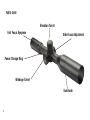
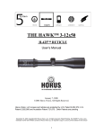
This manual should only be used for Elite 3.5-21x50 & 4.5-30x50 Tactical Riflescopes with these reticle designs: Bushnell Mil Dot Reticle Bushnell G2DMR Reticle Horus Vision H59 Reticle Horus Vision TRMR2 Reticle Including new models featuring Zero Stop PROUD USA COMPANY Lit #: 98-2293/01-13 TABLE OF CONTENTS Contents Page # Parts Guide 4 Fast Focus Eyepiece 5 Power Change Ring 5 Side Focus (Parallax) 5 Elevation and Windage Turrets 6 Special Note: Scopes Equipped with the Z-Lok™ Elevation Turret Setting a Zero Stop (Z-Stop™ models only) Resetting the Zero Stop (Z-Stop models only) 7 8-9 10-11 First Focal Plane Reticle 12 Bore Sighting and Zeroing the Scope 12 Bushnell Mil Dot Reticle 14 Bushnell G2DMR Reticle 20 Horus Vision H59 Reticle 24 Horus Vision TRMR2 Reticle 26 Maintenance and Storage 30 3 PARTS GUIDE Elevation Turret Fast Focus Eyepiece Side Focus Adjustment Power Change Ring Windage Turret Sunshade 4 Fast Focus Eyepiece The fast-focus eyepiece dial is found on the ocular end of the Bushnell Elite Tactical Riflescope. Use this adjustment to obtain a reticle image that appears sharp to your eyes. If adjustment is needed, look at a distant object for several seconds without using your scope. Then, shift your vision quickly, looking through the scope at a plain background. Turn the fast-focus eyepiece dial clockwise or counterclockwise until the reticle pattern is sharp and clear. The eyepiece has a large adjustment range and should be used in conjunction with the side focus (parallax) adjustment to obtain maximum resolution when viewing targets at long ranges. Power Change Ring Changing the magnification of the Bushnell Elite Tactical Riflescope can be accomplished by grasping the knurled knob marked with the scope’s magnification range (located on the far end of the ocular bell end). Turn the power change ring clockwise for higher magnifications, counterclockwise for lower magnifications. The magnification setting can be identified by noting the number that is in front of the stationary dot on the scope tube. Side Focus The Side Focus adjustment corrects Parallax error. Parallax error is experienced when the intended target and the reticle are not on the same focal plane. The side focus adjustment relocates an optical element within the scope, manipulating the incoming image to appear on the same focal plane as the reticle within the riflescope, thus eliminating parallax error. Parallax error results in inconsistencies regarding point of impact. This can be best experienced by looking at a 100 yard target with the side focus set to 500 yards. While slightly moving your head left and right, or up and down, you will notice movement at the location where the crosshairs intersect. However, if you change your side focus adjustment to 100 yards while looking at the 100 yard target, the intersection of the crosshairs will not move. Please note the distance markings on the dial are intended as reference points only. Exact side focus adjustments may needed after making adjustments to the eyepiece in order to achieve a high resolution, parallax free image. 5 Elevation and Windage Turrets The Bushnell Elite Tactical Riflescope features T-Lok™ (locking) turrets, which provide audible and visual references. When a turret is lifted (elevated) into the upward position it can be rotated in either direction to make appropriate adjustments. Each turn of the turret provides an audible “click” which coincides with a movement of the visible reference point on the turret knob. Additionally, clicks can be felt by your fingers as the turret knob moves. Each “click” represents .1 mil. After adjustments are made, the turret can be pushed back into the downward position to prevent movement, or left elevated and ready for further adjustments if preferred. With the turrets pulled fully upward, rotate the elevation turret knob counterclockwise to move the reticle plane up, or clockwise to move it down. Rotate the windage dial counterclockwise to move the reticle plane right, or clockwise to move it left. Bushnell HDMR and DMR riflescopes provide 5 mils of adjustment per complete revolution of the turret. Bushnell ERS and XRS riflescopes with Z-Stop™ provide 10 mils of adjustment per revolution. After adjustments have been made, you can reset the turret to zero by following the steps below: 1. Ensure the turret is in the lock position. 2. Use a coin or flathead screwdriver to remove the turret screw found on top of the turret knob, being careful not to displace the o-ring found under the turret knob. 3. Remove the turret knob and return it to the turret, with the “zero” mark on the knob lining up with the vertical index line on the turret. 4. Return turret screw to top of knob and tighten down, making sure the turret knob is in the locked position so the turret knob does not turn while tightening the screw. step 1 6 step 2 step 3 step 4 Special Note: Scopes Equipped with the Z-Lok™ elevation turret If your scope is equipped with the Z-Lok zero stop elevation turret, the scope’s windage and elevation controls are positioned in the center of their travel at the factory. This will allow a minimum of 15 mils (or 50 moa) of reticle travel in the up or down direction on the elevation turret. The zero stop is not set at the factory, and will not interfere with reticle travel in the up or down direction. Use of the zero stop is optional and the scope will operate normally with the Z-Lok remaining at the original factory set position. If you decide not to use the Z-Lok, after zeroing your weapon please refer back to the instructions on page 6, which will help you to re-index your turret(s) to the zero position. If you would like to engage the Z-Lok after zeroing your weapon please proceed to the next section. 7 SETTING A ZERO STOP (Z-Stop™ Models Only) For ERS and XRS Tactical Scopes with a zero stop feature, follow these steps to initially set your zero stop: 1) Ensure the turret is in its locked position by pressing down on the turret knob. Remove the turret knob cap screw using a coin or flathead screwdriver, set aside (Fig. 1). 2) Remove the turret knob and set aside (Fig. 2). There are two holes on the black inner locking cap which will provide access to the zero stop set screws. Loosen the two Allen screws found on the black inner locking cap 1 ½ turns counter-clockwise with the 1.5 mm Allen wrench (provided with your scope) (Fig.3). In order to prevent loss, the set-screws are permanently held in place by a keeper nut and cannot be completely removed. 3) Pull up the black inner locking cap. Place the long end of the hex wrench in the hole in the top of the black inner locking cap and push down the brass zero stop (Fig. 4). You should feel the zero stop seat as it hits bottom, the amount of movement is dependent on the location of the zero. 4) Now with the inner locking cap in the up position rotate it in a clockwise direction until you hear a distinct “click” (Fig. 5). This indicates that the zero stop is set at your zero position. Push the inner locking cap to its downward position (Fig. 6). Fig. 1 8 Fig. 2 Fig. 3 Fig. 4 SETTING A ZERO STOP (Z-Stop™ Models Only) Fig. 5 Fig. 6 Fig. 7 5) Utilizing the 1.5mm Allen wrench, re-tighten the zero stop set screws inside the black inner locking cap (Fig. 7). The screws should be tightened until you feel them seat and then an additional ¼ revolution (approximately 1.5-2 inch pounds). Do not over-tighten as this will cause damage to the screws. 6) Replace the turret knob on to the turret by aligning the splines in the turret cap and the turret and orient your turret to “O” position and seat the cap (Fig. 8 & 9). Once the cap is properly seated insure that the rubber o-ring is in place then replace cap screw and tighten, finger tight with a coin or until snug with a screw driver (Fig. 10). 7) Your zero stop is now set. Fig. 8 Fig. 9 Fig. 10 9 RESETTING THE ZERO STOP (Z-Stop™ Models Only) 1) Ensure the turret is in its locked position by pressing down on the turret knob. Remove the turret knob cap screw using a coin or flathead screwdriver (Fig. 1). 2) Remove the turret knob and set aside (Fig. 2). There are two holes on the black inner locking cap which will provide access to the zero stop set screws. Loosen the two Allen screws found on the black inner locking cap 1 ½ turns counter-clockwise (1.5mm Allen wrenchprovided) (Fig. 3). In order to prevent loss, the screws are permanently held in place by a keeper nut and cannot be completely removed. 3) Place a flathead screwdriver into the cross-slotted screw located in the middle of the inner locking cap (Fig. 4). Turn the screwdriver clockwise until a stop is felt (do not over tighten the screw at this point to prevent damage to the zero stop). Once the stop is felt, turn the screw back ¼ turn counter-clockwise (approx. 2.5-3 mils) in order to move the zero stop up off of its lowermost position. Fig. 1 Fig. 2 Fig. 3 10 Fig. 4 4) Utilizing the 1.5mm Allen wrench, re-tighten the zero stop set screws inside the black inner locking cap (Fig. 5). The screws should be tightened to approximately 1.5-2 inch pounds. Do not over-tighten as this will cause damage to the screws. 5) Push the inner cap to its “down” position (Fig. 6). Replace the turret knob onto the turret by aligning the splines in the turret cap and the turret (Fig. 7). Once the cap is properly seated (Fig. 8) insure that the rubber o-ring is in place replace cap screw and tighten, finger tight with a coin or until snug with a screw driver (Fig. 9). 6) You are now ready to re-zero your weapon. Once you have achieved proper zero, refer back to the steps for setting the zero stop on pg. 7. Fig. 5 Fig. 6 Fig. 7 Fig. 8 Fig. 9 11 First Focal Plane Reticle The Bushnell Elite Tactical Riflescopes covered by this manual have their reticles located in the first focal plane. Therefore, the reticle will increase in size when the magnification is increased. This feature allows the continued use of the mil measurement system contained in the reticle, regardless of the power setting. Second focal plane reticles restrict the user to making measurements at a specific power, as the reticle remains the same size and will not account for different magnification levels. Bore Sighting and Zeroing the Scope Bore sighting is a preliminary procedure to achieve proper alignment of the scope with the rifle bore. It is best done using a Bushnell Bore Sighter. If a bore sighter is not available, it can be done as follows: Remove the bolt and sight through the gun barrel at a 100 yard target. Then sight through the scope and bring the crosshairs to the same point on the target using the turrets or windage adjustments. Return the bolt and prepare to shoot down range at the 100 yard target. Your next step will be to zero the scope using live rounds. Fire your first shot and note the location of impact. You can use the turrets to change the point of impact accordingly. For example, if your first shot went 1 mil high and 1 mil left, adjust your elevation dial down 1 Mil and your windage dial 1 mil right. Always adjust in the opposite direction from your point of impact. As you fire your second shot, you should see the point of impact hit closer to your intended target. Multiple rounds may need to be fired before achieving consistent results. You may also use reticle within your scope to help decipher the correct adjustments. The following page shows how this works, using the H59 reticle as an example. 12 In the example to the left using the H59 reticle, the shooter was attempting to hit a target in the center of the crosshairs. The actual point of impact hit 4 Mils down and 3 Mils left indicated by the red dot. Adjust the elevation dial 4 Mils up/windage dial 3 Mils right. Another way to look at this is to determine what adjustment needs to be done with the turrets to move the red dot so it is centered in the middle of the crosshairs. (up 4 Mils/over to the right 3 Mils) 13 Bushnell Mil Dot Reticle The Bushnell Mil Dot Reticle provides a total of ten Mils on both the vertical and horizontal crosshairs. One Mil is measured from the middle of one dot to the middle of the next dot. The last Mil on the outer edges portion of the horizontal and vertical crosshair is measured from the center of the fourth Mil Dot from center to the edge of the thick line. You will notice the intersection of the crosshairs does not contain a Mil dot. This is to allow maximum target acquisition without interference from the reticle. 1 Mil The space from center-dot to center- dot is one mil, which is an angular measurement that widens with distance. One mil at 100 yards equals 3.6 inches, at 1000 yards, that same one mil will have widened by ten times to 36 inches. The distance is ten times further, so the mil represents a space that’s ten times larger. The Bushnell Elite Tactical scope features the Mil Dot reticle in the FIRST FOCAL PLANE. The reticle is placed after the magnification portion of the scope tube and results in both the target and reticle increasing or decreasing in size with different magnification levels. The first focal plane reticle will maintain accuracy regarding Mil Dot measurements. This design syncs the measurement of the Mil Dot in the scope with each power throughout its range thus; Mil Dot measurements can be used within any power of the scope. Some scopes have the Mil Dot reticle in the second focal plane. Second focal plane reticles do not change in size with a magnification change and therefore the measurements do not coincide. Second focal plane Mil Dot reticles will only provide a reference at a specific magnification. 14 The Mil Dot Reticle Measurement System in the First Focal Plane Applies at any Magnification Level. 2 Mils at 12x (100 yards) 2 Mils at 3.5x (100 yards) 15 Using the Mil Dot Reticle for Ranging The Equations: Size of target in yards X 1000 Size of Target in Mils = Range in Yards Size of target in inches X 27.778 Size of target in Mils Size of target in inches X 25.4 Size of target in Mils = Range in Yards = Range in Meters Example 1: Looking through the riflescope, I located a preset target that has a known size of 12”x12” square. By using the Mil Dots I measured the target to have a Mil reading of 1. What is my distance to the target? Known size of target: 12”x 12” Mil Reading: 1Mil 16 12 X 27.778 = 333.33 Yards 1 Mil Example 2: Take the same size target but now the Mil reading is .75 (from crosshair intersection to bottom of first Mil Dot). Known size of target: 12”x 12” Mil Reading: .75 Mil 12 X 27.778 .75 Mil = 444.44 Yards Converting Trajectory Data to Mil Holdovers To calculate holdovers you must first obtain your round’s trajectory data. Look at the ammunition manufacturer’s website, in a manufacturer’s brochure, or use a ballistic software program. You will need the Bullet Path data for a 100-yard zero, in hundred-yard increments. The following ballistic information example refers to the Federal .308 168-gr. BTHP Match Round and a 100-yard zero. The left column lists the cartridge’s trajectory in inches at 100-yard increments. The next column contains the mil-size in inches at these same distances. Divide the trajectory by the mil size at each distance to find the holdover in Mils. 17 Federal .308 168-gr BTHP Holdovers for a Mil-Dot Reticle 18 Distance Trajectory 1 Mil Size Actual Holdover 100 Yards 0 0 Mils 0 Mils 200 Yards 4.5” 7.2 Mils .62 Mils 300 Yards 15.9” 10.8 Mils 1.47 Mils 400 Yards 35.5” 14.4 Mils 2.46 Mils 500 Yards 64.6” 18.0 Mils 3.58 Mils Trajectory Mil Size at given Distance = Holdover Using the Mil Dot Reticle for Holdover Once you know how to range your target with the Mil Dot reticle, and using the previous example, you can use the reticle instead of the turrets to make adjustments with holdover. For example, your range tells you that the 12” target is 300 yards away, (12”*27.778) / (1.1Mil). Based on the Federal .308 Win ballistic info in the previous example, you will need to hold 1.47 Mils down on the vertical crosshair and fire. Yards Mil value in inches 100 3.6 200 7.2 300 10.8 400 14.4 500 18.0 600 21.6 700 25.2 800 28.8 900 32.4 1000 36.0 19 Bushnell G2DMR™ Reticle The G2DMR reticle, developed in conjunction with G.A. Precision, provides a clean reticle space while giving you the ability to range targets with extreme accuracy using .1 Mil reference points. The extended horizontal mil markings on the lower portion of the vertical crosshair can be used for both ranging and windage holds. The entire reticle is shown below, but the following pages will provide a detailed look at the markings on the horizontal and vertical crosshairs. 20 The Horizontal Crosshair On the horizontal crosshair, numerically designated Mil markings extend from the center of the crosshairs outward to the right in 2 Mil increments. To keep the reticle plane clean, the numbers were removed on the left side of the reticle but the reference points coincide with the markings from the right side of the crosshair. Moving from the center point to the right in the picture below measurements are as follows: .5 Mil, 1 Mil, 1.5 Mil, 2 Mil…etc. 1 Mil from center .5 Mil from center 1 Mil from center .5 Mil from center 21 Extending past the 8 Mil mark, the numerals stop. 1 Mil increments are then designated by the longer hash marks which measure 1.5 Mil in height from top to bottom. Ten .1 Mil markings are visible between each 1 Mil marking, continuing out to 13 Mils from center. The height from top to bottom of the .1 Mil markings is 1 Mil. The .1 Mil markings provide you with a very precise horizontal measurement of your target. 1 Mil consisting of ten .1 mil marks 1 Mil Mark 9 Mil Mark 1.5 Mil Height 1 Mil Height 22 1 Mil Mark The VerticAL Crosshair Similar to the horizontal crosshair, the vertical crosshair places the numerically designated Mil markings on only one side. Once again, the numerically designated markings are found in 2 Mil increments with hash marks every .5 Mil. Note the vertical cross hair extends to provide numerically designated markings up to 10 Mils from center. From the 11th Mil measurement downward the reticle returns to the .1 Mil markings, before the next 1 Mil marking is seen measuring 1.5 Mils across. The lower portion of the vertical crosshair is different than all other portions of the reticle. Starting with the 2 and 3 Mil mark, the horizontal hash mark seen in the picture below measures 1 Mil across. See list below for horizontal hash mark measurements extending down to 10 Mils. Mil Values of horizontal hash marks left to right across Vertical Crosshair A. 1 Mil B. 2 Mil C. 3 Mil D. 4 Mil E. 5 Mil At the 11th Mil mark the reticle returns to .1 Mil vertical markings. A. 1 Mil B. 2 Mil C. 3 Mil D. 4 Mil E. 5 Mil 23 Horus Vision H59 Reticle The H59 reticle is a “field-tuned” version of the H58 reticle from Horus Vision. The horizontal grid is widened by one mil for increased wind holdover. Additionally, the center cross has been turned into a “broken cross” so groupings are less obscured and more easily seen. The H59 reticle is free of the clutter of more complex reticles, while still providing more windage and elevation hold capability than any optic in its class. The clean design includes wind hold dots that extend beyond the grid. In addition to HorusVision’s standard gridded, mil-based reticle, the HDMR’s H59 reticle incorporates the Accuracy 1st Speed Shooting Formula to provide rapid moving target holds, as well as a system for engaging distant targets quickly without knowing specific ranges. CALCULATING HOLDS FOR ELEVATION The H59’s moving target lead lines incorporate the Accuracy 1st Speed Shooting Formula to help you rapidly determine an elevation hold your target without using the traditional mil relation formula for range-finding. The steps for determining an expedient hold are as follows: 1. Locate a 12” portion of a target. 2. F ind the line above the horizontal stadia that best brackets the 12” target between the moving target lead line and the horizontal stadia. 24 3. N ote the number corresponding to the lead line in step 2; divide that line value in half. For example, if the 12” target fits between the 4 mph lead line and the horizontal stadia line, divide that in half to get a value of 2. 4. Place the 2 mil elevation hold (usually expressed as “2 mils high” or “+2 mils”) on target and fire. This process works well for many cartridges and weapon systems,but not all will impact exactly the same. However this system should place you close enough to make a solid hit, all else being equal. If shooting with a different caliber or muzzle velocity, you may need to add to or subtract from the original elevation hold to adapt the formula for your needs. CALCULATING HOLDS FOR MOVING TARGETS The H59 reticle has a series of even numbers above the main horizontal stadia. These numbers represent speeds for moving targets at 2, 4, 6, 8 and 10 mph, with additional holds starting at 20 mils and continuing every 10 mph thereafter to the left and right. These speeds are optimized for .308 caliber, but may be used with many other calibers. To hold on a target moving at one of these speeds, simply hold the portion of the horizontal stadia that intersects with the short line nearest the number representing the target speed over the moving target, accounting for possible adjustments for distances different from optimal. If using the Horus grid (below 25 center) for elevation, use a hold point in line with the appropriate speed. To hold on a target traveling at a speed between markings (such as 5 mph) you hold between the even numbers on either side of it (4 and 6 mph). For more detailed information regarding this reticle and its use, please visit www.horusvision.com or call 650-588-8862 Horus Vision TRMR2 Reticle The TRMR2 is a refined-mil reticle. Precision mil-marking clusters interspersed throughout the reticle enable fast accurate measurements at .1, .2, .5 and 1 mil increments. With the 12” ranging brackets located on the lower portion of the vertical stadia, there is no need to make an additional adjustment once the correct bracket is found. The TRMR2 is a fast acting, precise reticle designed to engage targets quickly and accurately. CALCULATING HOLDS FOR ELEVATION The TRMR2 12” bracket system (Drop Finder) on the lower vertical stadia, incorporates the Accuracy First Speed Shooting Formula to help you rapidly determine an elevation hold for your target without using the traditional Mil relation formula for range finding. The steps for determining an expedient hold are as follows: 26 1. Locate a 12” portion of a target. 2. Find the bracket on the lower vertical stadia that best fits the target. You will notice 5 brackets are available with a ranging capability of over 600 yards when using Ballistic Coefficients of .4 (see diagram to the right). 3. Send your shot. This process works well for many cartridges and weapon systems, but not all will impact exactly the same. However, this system should place you close enough to make a solid hit, all else being equal. If shooting with a different caliber or muzzle velocity (BC’s), you may need to add to or subtract from the original elevation hold to adapt the formula for your needs. 1st Drop Down Bracket (.9 Mil) 2nd Drop Down Bracket (.8 Mil) 3rd Drop Down Bracket (.7 Mil) 4th Drop Down Bracket (.6 Mil) 5th Drop Down Bracket (.5 Mil) 27 CALCULATING HOLDS FOR MOVING TARGETS The TRMR2 reticle has 14 wind dots left to right. 7 wind dots to the left and 7 wind dots to the right of center. Each dot accounts for 3,4, or 5 mph of wind depending on the Ballistic Coefficient you are using. Ballistic Coefficient Wind Dot Value .3 5 mph .4 4 mph .5 3mph For example, if you were holding +8 Mils of elevation and accounting for a right to left crosswind at 20 mph wind using a .4 BC you would use the 5th wind mark. You will notice the 4th wind marking is designated by a cross rather than a dot. This can be used to make wind adjustments faster as you memorize the unique mark as a specific wind hold value (varies dependant on BC). Additionally, you will find wind dots located at the ½ mil marks down the vertical stadia. CALCULATING FOR MOVERS Calculations for movers have been designated by numbers (1-9). These numbers not only represent the elevation Mil markings as you move down the stadia but also represent holds for movers moving at 4 mph. To adjust for 4 mph movers, first adjust for elevation and then move reticle so the number is covering your intended target; send your shot. 28 holds at any range. HORIZONTAL STADIA The horizontal stadia holds a .2,.5,.8,1 Mil series from center throughout it length. The same series is found on the upper portion of the vertical stadia. Please note; starting at the 3.5 Mil marking the reticle offers .1 Mil markings for precise ranging. At the 4 Mil mark the previous series of .2,.5,.8,1 Mil returns. RETICLE FROM 10TH MIL TO 38TH MIL DOWN ON Vertical STADIA The standard Horus grid is found from the 10th Mil down on the vertical stadia to a total of 38 Mils. The Horus grid evolves reticles beyond outdated crosshairs and mil dots. The patented grid eliminates the need to adjust windage or elevation knobs. As a result you find your target faster, minimize frustrating mechanical factors and do away with counting clicks. The standard Horus grid can be used to mil targets and place holds at any range. Starting at the 3.5 Mil mark you will find a series of 5, .1 Mil markings HORIZONTAL STADIA The horizontal stadia holds a .2,.5,.8,1 Mil series from center throughout it length. The same series is found on the upper portion of the vertical stadia. Please note; *For more information regarding the Horus Vision TRMR2 Reticle please go to www.horusvision.com or call 650-588-8862 starting at the 3.5 Mil marking the reticle offers .1 Mil markings for precise ranging. At the 4 Mil mark the previous series of .2,.5,.8,1 Mil returns. *For more information regarding the Horus Vision TRMR2 Reticle please go to www.horusvision.com or call 650-588-8862 29 MAINTENANCE Your Bushnell Elite Tactical HDMR riflescope, though amazingly tough, is a precision instrument that deserves reasonably cautious care. 1. When cleaning the lenses, first blow away any dry dirt and dust, or use a soft lens brush. Fingerprints and lubricants can be wiped off with lens tissue, or a soft clean cloth, moistened with lens cleaning fluid. Microfiber cleaning cloths are also recommended. WARNING: Unnecessary rubbing or use of a coarse cloth may cause permanent damage to the lens coatings. 2. All moving parts of the scope are permanently lubricated. Do not try to lubricate them. 3. No maintenance is needed on the scope’s outer surface, except to occasionally wipe off dirt or fingerprints with a soft cloth. 4. Use lens covers whenever it is convenient. STORAGE • Avoid storing the scope in hot places, such as the passenger compartment of a vehicle on a hot day. The high temperature could adversely affect the lubricants and sealants. A vehicle’s trunk, a gun cabinet or a closet is preferable. • Never leave the scope where direct sunlight can enter either the objective or the eyepiece lens. Damage may result from the concentration (burning glass effect) of the sun’s rays. H59 and TReMoR reticle designs are used under license, and are protected by patents owned by Horus Vision, LLC. 30 ELITE® LIFETIME LIMITED WARRANTY We are so proud of our Bushnell® ELITE® Tactical HDMR™ Riflescopes that their materials and workmanship are warranted to be free of defects for the life of the ELITE Tactical HDMR Riflescope.The warranty is available to any owner of the ELITE Tactical HDMR Riflescope. No receipt or warranty card is required. This warranty does not cover damages caused by misuse or improper handling, installation or maintenance of the riflescope. At our option, we will repair or replace any defective ELITE Tactical HDMR Riflescope, which shall be your sole remedy under this warranty. In no event shall we be liable for transportation costs to us, costs of removal or reinstallation of the riflescope, or incidental or consequential damages. Some states do not allow the exclusion of limitation of incidental or consequential damages, so the above limitation or exclusion may not apply to you. No agent, representative, dealer or unauthorized employee of Bushnell has the authority to increase or alter the obligation of this warranty. Any return made under this warranty must be accompanied by the items listed below: 1) Name and address for product return 2) An explanation of the defect 3) You are responsible for transport of the defective product, but we will pay for shipping the repaired or replacement product back to you anywhere in the continental United States. 4) P roduct should be well packed in a sturdy outside shipping carton, to prevent damage in transit, to the following address: IN U.S.A. Send To: IN CANADA Send To: Bushnell Outdoor Products Bushnell Outdoor Products Attn.: Repairs Attn.: Repairs 9200 Cody 25A East Pearce Street, Unit 1 Overland Park, Kansas 66214 Richmond Hill, Ontario L4B 2M9 For products purchased outside the United States or Canada please contact your local dealer for applicable warranty information. In Europe you may also contact Bushnell at: Bushnell Germany GmbH European Service Centre Mathias-Brüggen-Str. 80 D-50827 Köln GERMANY Tel: +49 221 995568-0 Fax: +49 221 995568-20 This warranty gives you specific legal rights. You may have other rights which vary from country to country. ©2013 Bushnell Outdoor Products For further questions or additional information please contact: Bushnell Outdoor Products 9200 Cody, Overland Park, Kansas 66214 (800) 423-3537 www.bushnell.com ©2013 Bushnell Outdoor Products