1
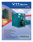
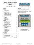
www.commercialcastiron.com
for Commercial Boiler Applications
The Burnham Commercial RTC Return Temperature Control provides an economical and effective means of boiler
protection from thermal shock and sustained condensing operation. The RTC monitors the boiler return water
temperature and operates a 3-way diverting valve and boiler circulator to maintain a minimum return temperature
of 135°F or greater. An outdoor reset function is also available to reset the system water temperature based on
outdoor air temperature. Studies indicate that resetting the boiler and system water temperature increases efficiency and reduces operating costs. The controls is available in two configurations: Basic RTC Kit and RTC kit with
Outdoor Reset Control.
3-way
Diverting
Valve
Boiler
Circulator
RTC
Return Temperature Control
Includes:
Outdoor Reset option
LCD display of return water temperature
Maintains
Minimum 135°F
Return Water
Temperature
Return Sensor
Monitors Boiler Return
Water Temperature
1
RTC RETURN TEMPERATURE CONTROL
Why Boiler Protection?
Today’s demands for comfort
and efficiency require greater
attention to the temperature and
volume of return water to the
boiler. Many premature boiler
failures can be traced to these two
uncontrolled variables. Operating
below minimum temperatures
and flow rates creates thermal
shock conditions and flue gas
condensation issues, each of which
can shorten the life expectancy of
a boiler. Other factors that affect
return temperature and flow
include:
• snow melt and radiant flooring applications
• complex system integration and
control
The concept of boiler protection
has existed for many years.
However, the primary focus in
hydronic systems is often the
demand and delivery design
characteristics. Frequently, little
attention is given to the heat
source – the boiler.
Controlling Return
Temperatures
The Burnham Commercial RTC Return
Temperature Control provides an
economical and effective means of
boiler protection from thermal shock
and sustained condensing operation.
By expanding the “boiler envelope”
to incorporate a 3-way valve and
flow control system, the RTC Return
Temperature Control maintains a
minimum return water temperature of
135°F or greater.
The RTC system is supplied as a kit
and can be incorporated into most
hydronic hot water applica-tions with
minimal modifications to the system
design and operation. It provides a
simple means for boiler protection and
an opportunity to increase operational
efficiency.
Outdoor Reset Option
The addition of the outdoor reset
option provides additional energy
savings by modulating the system
supply water temperature based upon
outdoor air temperature. This allows
the system to closely match the heating needs of the building regardless of
weather conditions.
Features Include:
• Indoor/Outdoor Reset Control
• Thermal Shock and Flue Gas Condensation Protection
• outdoor reset and warm weather shutdown
• Maintains Minimum Return Water Temperature
• misunderstanding the protection value of primary/secondary systems
• Simple Self-Diagnostic Test
Sequence with Error Messages
• conversion of steam or gravity flow systems to pumped water
systems, while retaining the original oversized distribution systems
• Off-Season Built-in Pump and
Valve Exerciser
• Adjustable Boiler Pump Purge
•24 Vac Floating Motor Actuator on 3-way Valve
Standard Equipment
Basic RTC Kit
3 x 12 Nipple with Tapping
24 Vac Actuator 3-way Valve
J-Box
Mounting Bracket
RTC Kit with Outdoor Reset
Basic RTC Kit with additional
items below:
917-14 Universal Sensor for Mixing
070 Outdoor Sensor
Additional Components
Boiler Circulator
one required per RTC kit
(not included)
Flange Kits for 3-way valves
available in 2-1/2” to 5” sizes
www.commercialcastiron.com
RTC Kit Selection Chart (1)
SELECT BOILER SIZE
20° ∆ T
—
—
V903
V904
V905
V1104
V906, V907, V908
V1105, V1106
V909, V910, V911
V1107, V1108, V1109
V912
V1110, V1111, V1112, V1113
V1114, V1115
V1116, V1117, V1118
V1119, V1120
V1121, V1122, V1123
BASED ON ∆ T (4)
VALVE
SIZE
(1) (2)
1.0 NPT"
1.25 NPT"
BASIC
RTC KIT
PART #
60160851
60160852
RTC KIT w/
OUTDOOR RESET
PART #
60160861
60160862
APPROXIMATE
SHIPPING
WEIGHT
17
17
1.5 NPT"
60160853
60160863
20
2.0 NPT"
60160854
60160864
24
2.5" FLG (3)
60160855
60160865
47
2.5" FLG (3)
60160856
60160866
47
3.0" FLG
60160857
60160867
55
—
4.0" FLG
60160858
60160868
80
—
5.0" FLG
60160859
60160869
93
40° ∆ T
V903
V904
V905, V906
V1104, V1105
V907, V908, V909
V1106, V1107, V1108
V910, V911, V912
V1109, V1110, V1111
V1112, V1113, V1114
V1115, V1116, V1117
V1118 V1119, V1120
V1121, V1122, V1123
1. Requires addition of a boiler circulator, to be provided by installer. See back page for circulator selection.
2. Pipe size varies on application – Refer to I & O Manual for details.
3. The 2.5” valves have diferent Cv values. Refer to the I & O Manual for details.
4. RTC can be used on other Burnham Commercial products. Consult factory for application.
RTC Return Temperature Control Specification
1. The Burnham RTC Return Temperature Control is a CSA certified microprocessor based control that will control boiler return water temperature to prevent thermal shock and flue gas condensation.
2. The control shall have a 120V power supply with a built in 24V transformer to power a floating action type actuator.
3. The control shall provide a 24V floating output signal to modulate a three-way or a four-way diverting valve based on a signal from the return temperature sensor mounted in the return piping to the boiler.
4. The control shall have an LCD display to view system status and operating information.
5. The control shall have a non-volatile memory to monitor supply and return water temperatures and boiler run times.
6. The control shall have a boiler minimum setting of 135°F and shall not be programmable any lower than 135°F.
7. The control shall have a warm weather shut down feature, a heat demand input, boiler contact and pump contact.
8. The control must receive a heat demand before it can operate. When the demand is removed, the diverting valve shall fully close before it is allowed to respond to the new heat demand.
9. The control shall have a test sequence to ensure proper component operation, an adjustable pump post purge of zero to 240 seconds, exercising of pump and diverting valve, error messages when it detects a malfunction and an adjustable actuator motor speed setting of 30 to 230 seconds.
10. The control shall have the ability to operate with an outdoor reset function. This requires the use of a mixed water sensor and an outdoor air sensor.
www.commercialcastiron.com
20° ∆ T Circulator Sizing (1)
TACO (1)
BELL & GOSSETT (1)
GRUNDFOS (1)
BOILER TOTAL
SIZE
GPM MODEL # IMP " HP
RPM
MODEL #
IMP " HP RPM
MODEL #
IMP " HP
V903A
35
IL 111
N/A
1/8
1725
PL-36-1.5"
Std. 1/6 3300 UPS32-40/4
3.39 1/3
V904A
48
1615
4.7
1/3
1750
PL-75-2"
Std. 1/6 3400 UPS32-80/4
2.52 1/2
V905A
65
1611
4.5
1/3
1750
PL-130-2"
Std. 2/5 3200 UPS40-80/4
4.86 1/2
V906A
81
KV2006
4.3
1
1750
PL-130-2"
Std. 2/5 3200 UPS40-80/4
4.86 1/2
V907A
96
1635
4.5
1/2
1750
PL-130-2"
Std. 2/5 3200 UPS50-80/4
4.97 3/4
V908A
111
1635
4.9
3/4
1750
Ser. 60, Mod. 610-2
4
1/2 1750 UPS50-80/2
2.91 3/4
V909A
134
KV3006
4.7
1
1750
Ser. 60, Mod. 610-2
4
1/2 1750
TP80-40/4
3.73 1/2
V910A
153
KV3006
5.0
1
1750
Ser. 80, Mod. 3x3x7B
5
1
1750 TP100-40/4
4.10
1
V911A
171
KV3006
5.3
1
1750
Ser. 80, Mod. 3x3x7B
5
1
1750 TP100-40/4
4.10
1
V912A
190
KV3007
5.6
1
1750
Ser. 80, Mod. 3x3x7B
5
1
1750 TP100-80/4
5.24
2
V1104
67
KV2606
4.7
1
1750
PL-130-2"
Std. 2/5 3200 UPS40-80/4
4.86 1/2
V1105
86
KV2006
4.5
1
1750
PL-130-2"
Std. 2/5 3200 UPS40-80/4
4.86 1/2
V1106
107
1635
4.8
3/4
1750
Ser. 60, Mod. 610-2
4
1/2 1750 UPS50-80/4
4.97 3/4
V1107
128
KV3006
4.4
1
1750
Ser. 60, Mod. 610-2
4
1/2 1750 UPS50-80/2
2.91 3/4
V1108
152
KV3006
5.0
1
1750
Ser. 80, Mod. 3x3x7B
5
1
1750 TP100-40/4
4.1
1
V1109
173
KV3007
5.5
1
1150
Ser. 80, Mod. 3x3x7B
5
1
1750 TP100-40/4
4.1
1
V1110
194
KV3007
5.5
1
1150
Ser. 80, Mod. 4x4x7
5.5
3/4 1150
—
—
—
V1111
215
KV3007
6.0
1
1150
Ser. 80, Mod. 4x4x7
5.5
3/4 1150
—
—
—
V1112
233
KV3007
6.2
1
1150
Ser. 80, Mod. 5x5x7
5.25 3/4 1150
—
—
—
V1113
250
KV4007
5.6
1
1160
Ser. 80, Mod. 5x5x7
5.375 3/4 1150 UPS80-160/2 3.56
3
V1114
273
KV4007
5.8
1
1160
Ser. 80, Mod. 5x5x7
5.25 3/4 1150
—
—
—
V1115
296
KV5007
5.7
1
1160
Ser. 80, Mod. 5x5x7
5.5
1
1150
—
—
—
V1116
313
KV5007
5.5
1
1160
Ser. 80, Mod. 5x5x7
5.5
1
1150
—
—
—
V1117
335
KV5007
5.8
1
1160
Ser. 80, Mod. 5x5x7
5.5
1
1150
—
—
—
V1118
358
KV5007
5.9
1-1/2 1160
Ser. 80, Mod. 5x5x7
5.875 1.5 1150
—
—
—
V1119
374
C13009
6.3
1-1/2 1160
Ser. 80, Mod. 5x5x7
6
1.5 1150
—
—
—
V1120
396
C13009
6.5
1-1/2 1160
Ser. 80, Mod. 5x5x7
6.5
1.5 1150
—
—
—
V1121
417
C14007
6.6
1-1/2 1160
Ser. 80, Mod. 5x5x7
6.5
1.5 1150
—
—
—
V1122
433
C14007
6.7
2
1160
Ser. 80, Mod. 6x6x7
5.625 1
1150
—
—
—
V1123
455
C14007
6.9
2
1160
Ser. 80, Mod. 6x6x7
6
1.5 1150
—
—
—
1. For any motor over 1/3 hp, use additional relay for single phase power. Use motor starter for 3 phase power.
RPM
1667
3400
1587
1587
1607
3426
1750
1750
1750
1750
1587
1688
1694
3426
1750
1750
—
—
—
3513
—
—
—
—
—
—
—
—
—
—
ARMSTRONG (1)
MODEL #
IMP " HP
E-10
Full
1/6
E-16
Full
1/6
S-46
4.25 1/3
S-46
4.25 1/3
4380 3x3x6
5.04 1/3
4380 3x3x6 5.567 1/2
4380 3x3x6
5.23 1/3
4380 4x4x6 4.971 1/2
4380 4x4x6 5.371 1/2
4380 4x4x6 4.891 1/2
S-45
3.875 1/4
4380
4.529 1/3
4380 3x3x6 5.418 1/2
4380 3x3x6 5.057 1/3
4380 4x4x6 4.983 1/2
4380 4x4x6
5.01 1/2
4380 4x4x6
4.91 1/2
4380 4x4x6 5.149 1/2
4380 4x4x6
5.78 3/4
4380 4x4x6
5.9
3/4
4380 4x4x6
6
3/4
4380 5x5x8
7.03 1.5
4380 6x6x8 5.662 1.5
4380 6x6x8
5.72 1.5
4380 6x6x8 5.774 1.5
4380 6x6x8 5.811 1.5
4380 6x6x8
5.16 1.0
4380 6x6x8 5.319 1.0
4380 6x6x8
5.3
1.0
4380 6x6x8
6.56 1.0
RPM
1800
1200
1200
1200
1200
1200
1200
1200
1200
1200
1800
1200
1200
1200
1200
1200
1200
1200
1200
1200
1200
1200
1200
1200
1200
1200
1200
1200
1200
1200
ARMSTRONG (1)
MODEL # IMP " HP
S-25
2.75 1/6
S-25
2.75 1/12
E-8
Full
1/6
S-35
3.375 1/6
S-46
3.375 1/4
S-45
3.875 1/4
S-46
3.875 1/3
4380 3x3x6 4.998 1/3
4380 3x3x6 4.667 1/3
4380 3x3x6 5.019 1/3
E-8
Full
1/6
S-35
3.375 1/6
S-45
3.875 1/4
S-45
3.875 1/4
S-46
4.25 1/3
S-46
4.25 1/3
4380 3x3x6 5.147 1/3
4380 3x3x6 5.579 1/2
4380 3x3x6 5.119 1/3
4380 3x3x6
5.0
1/3
4380 4x4x6 4.569 1/3
4380 4x4x6 4.92 1/2
4380 4x4x6 5.168 1/2
4380 4x4x6 5.520 3/4
4380 4x4x6 4.654 1/3
4380 4x4x6 4.808 1/3
4380 4x4x6 5.03 1/2
4380 4x4x6 5.21 1/2
4380 4x4x6 6.19 1/2
4380 4x4x6 5.520 3/4
RPM
1800
1800
3600
1800
1800
1800
1800
1200
1200
1200
3600
1800
1800
1800
1800
1800
1200
1200
1200
1200
1200
1200
1200
1200
1200
1200
1200
1200
1200
1200
40° ∆ T Circulator Sizing (1)
BOILER TOTAL
SIZE
GPM
V903A
17
V904A
24
V905A
32
V906A
40
V907A
48
V908A
56
V909A
67
V910A
76
V911A
86
V912A
95
V1104
33
V1105
43
V1106
53
V1107
64
V1108
76
V1109
86
V1110
97
V1111
108
V1112
117
V1113
125
V1114
137
V1115
148
V1116
156
V1117
168
V1118
179
V1119
187
V1120
198
V1121
209
V1122
217
V1123
228
MODEL #
007
0010
111C
121C
120C
1611
122C
121C
131
1635
111
120
120
121
131
121
1635
1635
1635
1635
1635
KV3006
KV3006
KV3007
KV3007
KV3007
KV3007
KV3007
KV3007
KV3007
TACO (1)
IMP " HP
N/A
1/25
N/A
1/8
N/A
1/8
N/A
1/7
N/A
1/6
4.1
1/4
N/A
1/4
N/A
1/4
N/A
1/3
4.5
1/2
N/A
1/8
N/A
1/6
N/A
1/6
N/A
1/4
N/A
1/3
N/A
1/4
4.5
1/2
4.8
3/4
4.9
3/4
5.2
3/4
5.5
1
4.9
1
5.1
1
5.9
1
5.6
1
5.6
1
5.7
1
5.9
1
6.1
1
6.3
1
RPM
3250
3250
1725
1725
1725
1750
1725
1725
1725
1750
1725
1725
1725
1725
1725
1725
1750
1750
1750
1750
1750
1750
1750
1160
1160
1160
1160
1160
1160
1160
BELL & GOSSETT (1)
MODEL #
IMP " HP
NRF-33
Std.
1/5
PL-36
Std.
1/6
PL-36
Std.
1/6
PL-45
Std.
1/6
PL-75
Std.
1/6
PL-75
Std.
1/6
PL-130-2"
Std.
2/5
PL-130-2"
Std.
2/5
PL-130-2"
Std.
2/5
PL-130-2"
Std.
2/5
PL-1361-1/2"
Std.
1/6
PL-75
Std.
1/6
PL-75
Std.
1/6
PL-130-2"
Std.
2/5
PL-130-2"
Std.
2/5
PL-130-2"
Std.
2/5
PL-130-2"
Std.
2/5
Ser. 60, Mod. 610-2
4
1/2
Ser. 60, Mod. 610-2
4
1/2
Ser. 60, Mod. 610-2
4
1/2
Ser. 80, Mod. 3x3x7B
5
1
Ser. 80, Mod. 3x3x7B
5
1
Ser. 80, Mod. 3x3x7B
5
1
Ser. 80, Mod. 3x3x7B
5
1
Ser. 80, Mod. 3x3x7B
5
1
Ser. 80, Mod. 3x3x7B
5
1
Ser. 80, Mod. 3x3x7B
5
1
Ser. 80, Mod. 3x3x7B
5.5 1-1/2
Ser. 80, Mod. 3x3x7B
5.5 1-1/2
Ser. 80, Mod. 3x3x7B
5.5 1-1/2
RPM
2950
3300
3300
3300
3400
3400
3200
3200
3200
3200
3300
3400
3400
3200
3200
3200
3200
1750
1750
1750
1750
1750
1750
1750
1750
1750
1750
1750
1750
1750
GRUNDFOS (1)
MODEL #
IMP " HP
UPS32-40/4
3.39 1/3
UPS32-40/4
3.39 1/3
UPS32-40/4
3.39 1/3
UPS32-80/2
2.52 1/2
UPS32-80/2
2.52 1/2
UPS40-80/4
4.86 1/2
UPS40-80/4
4.86 1/2
UPS40-80/4
4.86 1/2
UPS40-80/4
4.86 1/2
UPS50-80/4
4.97 3/4
UPS32-40/4
3.39 1/3
UPS32-80/2
2.52 1/2
UPS32-80/2
2.52 1/2
UPS40-80/4
4.86 1/2
UPS40-80/4
4.86 1/2
UPS40-80/4
4.86 1/2
UPS50-80/4
4.97 3/4
UPS50-80/4
4.97 3/4
UPS50-80/4
4.97 3/4
UPS50-80/4
4.97 3/4
UPS50-80/4
5.03 1/2
UPS50-160/2
4.1
1
UPS50-160/2 3.57
3
UPS50-160/2 3.57
3
UPS100-40/4 3.57
3
UPS100-40/4 3.57
3
UPS100-40/4 3.57
3
UPS80-160/2 3.57
3
UPS80-160/2 3.57
3
UPS80-160/2 3.57
3
RPM
1594
1667
1712
3400
3400
1450
1587
1587
1688
1607
1667
3281
3400
1587
1688
1688
1694
1694
1607
1694
1694
3395
3395
3513
1712
1712
1712
3513
3513
3513
1. For any motor over 1/3 hp, use additional relay for single phase power. Use motor starter for 3 phase power.
Form No. PL81465701000-9/07-5Ms
©2011 Burnham Commercial - Lancaster, PA
Phone: 1-888-791-3790
2
www.burnhamcommercialcastiron.com
4
Printed in the U.S.A.