1
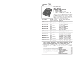
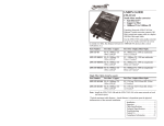
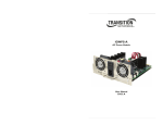
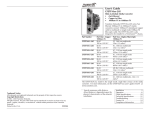
User’s Guide
BSS Audio MC-1
Stand-Alone Media Converter
• Gigabit Ethernet
• Copper to Fiber
• 1000Base-T to 1000Base-SX/LX
BSS Audio MC-1 Gigabit Ethernet media
converter connects 1000Base-T
shielded or unshielded twisted-pair copper
cable to 1000Base-SX or 1000Base-LX, fiberoptic cable. MC-1 is a standalone media converter
MC-1
RJ-45 1000Base-T
100 m (328 ft)*
SC, 1000Base-LX, 1310 nm single mode
10 km (6.2 miles)*
*Typical maximum cable distance. Actual
distance is dependent upon the physical
characteristics of the network installation.
Installation . . . . . . . . . . . . . . . . . .3
Operation . . . . . . . . . . . . . . . . . . .7
Cable Specifications . . . . . . . . . . .9
Technical Specifications . . . . . . .11
Troubleshooting . . . . . . . . . . . . .12
Contact Us . . . . . . . . . . . . . . . . .13
Compliance Information . . . . . . .15
Installation
Set the 6-position switch
The 6-position switch is located
on the side of the media
converter.
• Use a small flat blade
screwdriver to set the
recessed switches.
• All switches are shown in
the default position, UP.
1. Remote Fiber Fault Detect
2. Pause (symmetric)
3. Pause (asymmetric)
4. Transparent Link Pass-Through
5. Auto-Negotiation
6. Loop Back
Note: Switch positions S2 and S3 work together to configure the media
converter for Pause conditions.
S1 Remote-Fault Detection
up
Disabled
down
Enable
S2 & S3 work in combination
Pause
10 sw position 2 up and 3 down:
01 sw position 2 down and 3 up:
11 sw positions 2 and 3 up:
00 sw positions 2 and 3 down:
Symmetric
Asymmetric
Pause is OFF (default position)
Symmetric and Asymmetric
S4 Transparent Link Pass-Through
up
Enable Link Pass-Through
down
Disable Link Pass-Through
S5 Fiber Auto-Negotiation
up
Disable Fiber Auto-Negotiation for the fiber link
(default setting)
down
Enable Fiber Auto-Negotiation for the fiber link
S6 Loop Back
up
Disable RX/TX signal loop back (default setting)
down
Enable RX/TX signal loop back
2
BSS Audio 800-931-2357 8760 South Sandy Parkway, Sandy, Utah 84070
www.bssaudio.com 800-931-2357
3
Installation -- Continued
Installation -- continued
Install the fiber cable
Install Mode
During installation, set converter DIP switch 4 DOWN; leave all other switches
in the UP position (default). This disables Transparent Link Pass-Through and
Auto-Negotiation, allowing individual copper and fiber links to be established
(both copper port LEDs will turn ON with each device-to-device connection)
independent of a complete end-to-end connection.
1.
2.
Operation Mode
After installation is complete (all copper and fiber ports connected and linked),
set all switches to the UP position (default)).
3.
Locate a 1000Base-SX/LX compliant fiber cable with male, two-stranded
TX to RX connectors installed at both ends.
Connect the fiber cables to the MC-1 media converter as
described:
• Connect the male TX cable connector to the female TX port.
• Connect the male RX cable connector to the female RX port.
Connect the fiber cables to the other device (another media converter,
hub, etc.) as described:
Fiber Auto-Negotiation
Fiber Auto-Negotiation allows the fiber interface to detect and then advertise the
supported features of the remote device; this occurs only when a fiber cable is
connected to a device with a negotiating port. The process is as follows:
1.
2.
3.
4.
The fiber interface detects the supported features of the remote partner.
These abilities are passed to the twisted-pair interface and advertised.
Once the twisted-pair interface has a link at the highest common
capability, it passes the result to the fiber interface.
The fiber interfaces then start advertising these capabilities. At this point,
the link between the fiber and the negotiating port is complete.
If the MC-1 is connected via fiber to another MC-1, both media converters
must have the Fiber Auto-Negotiation setting disabled (switch 5 UP).
RX
RX
TX
TX
Device
•
•
Device
Connect the male TX cable connector to the female RX port.
Connect the male RX cable connector to the female TX port.
Note: Transparent Link Pass-Through (switch position 4 enabled) cannot be
turned OFF (disabled) when Fiber Auto-Negotiation is ON (enabled).
4
BSS Audio 800-931-2357 8760 South Sandy Parkway, Sandy, Utah 84070
www.bssaudio.com 800-931-2357
5
Installation -- Continued
Status LEDs
Install the copper cable
1.
2.
3.
Operation
Locate a 1000Base-T compliant copper cables with male, RJ-45
connectors installed at both ends.
Connect the RJ-45 connector at one end of the cable to the RJ-45 port on
the MC-1 media converter.
Connect the RJ-45 connector at the other end of the cable to the RJ-45
port on the other device (switch, workstation, etc.).
Use the status LEDs to monitor the MC-1 media converter operation
in the network.
PWR (Power)
ON = Connected to external AC power.
LKF
(Fiber link)
RXC
(Copper receive) Flashing =
ON = Fiber Connection
Duplex
Copper Link connection
ON =
Full
RJ-45 port
on the other device
(switch, work station, etc.)
Power the media converter
AC
The external power supply provided with this device is UL listed by the
manufacturer of the power supply.
1.
Install the power adapter cord to the back of the media converter.
2.
Connect the power adapter plug to AC power.
3.
Verify that the media converter is powered by observing the illuminated
LED power indicator light.
Converter R ear Panel
PWR
RJ-45 port
on the media
converter
LKF
RXC LED
TX
1000Base-X
Receiving data on the copper link.
ON =
Duplex LED
RX
1000Base-T
Remote-Fault Detect
Remote fiber fault detect (RFD) monitors the status of the fiber link. RFD must
only be enabled on the remote converter. If RFD is enabled in the device at
each end of the link, a link pass-through event will put the converters into an
unrecoverable state (unable to establish a link).
Pause
The pause feature can improve network performance by allowing one end of
the link to signal the other to discontinue frame transmission for a set period
of time to relieve buffer congestion.
The pause feature can be set to one of four settings:
• Disable (i.e., no pause)
• Symmetrical pause
• Asymmetric TX (transmit) pause
• Asymmetric RX (receive) pause
Enable the pause feature if it is present on ALL network devices attached to
the media converter(s); otherwise, disable the pause feature.
AutoCross (always on)
P ower Connector
6
BSS Audio 800-931-2357 8760 South Sandy Parkway, Sandy, Utah 84070
The AutoCross feature allows either straight-through (MDI) or crossover (MDIX) cables to be used when connecting to 10Base-T, 100Base-TX, or 1000BaseT devices, such as hubs, transceivers, or network interface cards (NICs).
AutoCross determines the characteristics of the cable connection and
automatically configures the unit to link up to its companion device regardless
of the cable configuration.
www.bssaudio.com 800-931-2357
7
Operation - Continued
Cable Specifications
Link Pass-Through
The physical characteristics must meet or exceed IEEE 802.3™ specifications.
The Link Pass-Through feature allows the media converter to monitor both the
fiber and copper RX (receive) ports for loss of signal. Refer to the illustration
below. For example, in the event of a loss of an RX signal (1), the media
converter will automatically disable the fiber TX (transmit) signal (2), thus,
“passing through” the link loss (3). The far-end device is automatically notified
of the link loss (4), which prevents the loss of valuable data unknowingly
transmitted over an invalid link.
media converter A
disables the fiber TX link
Near-End
Device
1
Media
Converter A
2
original fault
on the copper link
media converter B
loses the fiber RX link
3
Media
Converter B
4
Far-End
Device
media converter B
disables the copper link
Transparent Link Pass-Through
Transparent Link Pass-Through operates similar to Link Pass-Through with one
exception: the fiber link between the converters remains active. A signal is
passed through to the remote converter, causing it to shutdown the copper
link, notifying the end device of the link failure.
Fiber cable
Bit Error Rate:
Single mode fiber (recommended):
Multimode fiber (recommended):
Multimode fiber (optional):
<10-9
9 µm
62.5/125 µm
100/140, 85/140, 50/125 µm
BSS Audio MC-1
Fiber-optic Transmitter Power:
Fiber-optic Receiver Sensitivity:
Link Budget:
1310 nm single mode
min: -9.5 dBm
max: -3.0 dBm
min: -20.0 dBm
max: -3.0 dBm
10.5 dB
Copper cable (Category 5 -- minimum requirement)
• Gauge = 24 to 22 AWG; Attenuation = 22.0 dB /100m @ 100 MHz
• Straight-through OR crossover cable may be used.
• Shielded twisted-pair (STP) OR unshielded twisted-pair (UTP) may be used
• All pin pairs (1&2, 3&6, 4&5, 7&8) are active in a gigabit network.
• Use only dedicated wire pairs for the active pins; e.g., blue/white & white/blue,
orange/white & white/orange, etc.
• Do not use flat or silver satin wire.
Auto-Negotiation
Auto-Negotiation enables automatic configuration to achieve the best possible
mode of operation over a link between devices. A device with this feature
enabled will broadcast its speed (10Mbs, 100Mbs, etc.) and duplex (half/full)
capabilities to another device with this feature, then negotiate the best mode
of operation between them—no user intervention required.
Fiber Auto-Negotiation
Fiber Auto-Negotiation allows the fiber interface to detect and then advertise
the support abilities of the remote device. It is supported only when the fiber
is connected to a device with a negotiating port.
Loop Back
This diagnostic feature enables the media converter to loop back the signal
from the RX port to the TX port for testing and troubleshooting purposes. Test
signals from a bit-error test unit can then be inserted into either the copper or
fiber link to test a particular segment.
This type of diagnostic test can only be performed from the local to the
remote device with loop back enabled on the remote device.
SNMP
Note: SNMP is not supported in the MC-1.
8
BSS Audio 800-931-2357 8760 South Sandy Parkway, Sandy, Utah 84070
www.bssaudio.com 800-931-2357
9
Technical Specifications
For BSS Audio Model MC-1 or equivalent
Standards:
IEEE 802.3ab™, IEEE 802.3 2000
Data Rate / Delay:
1000 Mbs/300 nsec
Dimensions:
3.25" x 0.1" x 4.8" (82mm x 25mm x 122mm)
Weight:
3 oz. (91 g) approximately
Power Consumption:
5.4W, 450mA @ 12VDC
Packet Size:
10 Kbytes (maximum)
MTBF*
382,000 hours (MIL217F2 V5.0) (MIL-HDBK-217F)
1,345,000 hours (Bellcore7 V5.0)
Operating Temp:
Storage Temp:
Humidity:
Altitude:
Tmra** 0°C to 50°C (32°F to 122°F)
-15°C to 65°C (5°F to 149°F)
10% to 90%, non condensing
0 to 10,000 feet
Warranty:
Lifetime
*MTBF is estimated using the predictability method. This method is based on MIL-217F at
25°C ambient temperature, typical enclosure heat rise of 10°C, and nominal operating
conditions and parameters. Installation and configuration specific MTBF estimates are
available upon request. Contact Technical Support.
**Manufacturer’s rated ambient temperature.
For the most up-to-date information on the MC-1 media converter, view the
user’s guide on-line at: www.bssaudio.com.
The fiber optic transmitters on this device meet Class I Laser safety requirements per IEC825/CDRH standards and comply with 21 CFR1040.10 and 21CFR1040.11.
WARNING: Visible and invisible laser radiation when open. Do not stare into the beam or
view the beam directly with optical instruments. Failure to observe this warning could
result in an eye injury or blindness.
WARNING: Use of controls, adjustments or the performance of procedures other than
those specified herein may result in hazardous radiation exposure.
IMPORTANT: Copper based media ports, e.g., Twisted Pair (TP) Ethernet, USB, RS232,
RS422, RS485, DS1, DS3, Video Coax, etc., are intended to be connected to intra-building
(inside plant) link segments that are not subject to lightening transients or power faults.
Copper-based media ports, e.g., Twisted Pair (TP) Ethernet, USB, RS232, RS422, RS485,
DS1, DS3, Video Coax, etc., are NOT to be connected to inter-building (outside plant) link
segments that are subject to lightening transients or power faults.
10
BSS Audio 800-931-2357 8760 South Sandy Parkway, Sandy, Utah 84070
www.bssaudio.com 800-931-2357
11
Troubleshooting
If the media converter fails, isolate and correct the fault by determining the
answers to the following questions and then taking the indicated action:
1.
Is the PWR (power) LED illuminated?
NO
• Is the power adapter the proper type of voltage and cycle frequency
for the AC outlet?
• Is the power adapter properly installed in the media converter and in
the outlet?
• Contact Tech Support: 1-800-931-2357.
YES
• Proceed to step 2.
2.
Is the RXC (copper link) LED illuminated?
NO
• Check the twisted-pair copper cables for proper connection.
• Contact Tech Support: 1-800-931-2357.
YES
• Proceed to step 3.
3.
Is the LKF (fiber link) LED illuminated?
NO
• Check the fiber cables for proper connection.
• Verify that the TX and RX cables on the media converter are
connected to the RX and TX ports, respectively, on the other device.
• If the media converter is connected to another MC-1 using
fiber, verify the fiber Auto Negotiate is disabled (DIP-switch 5 in the
UP position).
• Contact Tech Support: 1-800-931-2357.
YES
• Proceed to step 4.
4.
Is the RXC (copper receive) LED flashing?
NO
• If there is activity on the 1000Base-T port, disconnect and reconnect
the twisted-pair copper cable to restart the initialization process.
• Restart the workstation to restart the initialization process.
• Contact Tech Support: 1-800-931-2357.
YES
• Contact Tech Support: 1-800-931-2357 .
12
BSS Audio 800-931-2357 8760 South Sandy Parkway, Sandy, Utah 84070
Contact Us
Technical support
1-800-931-2357
Address
BSS Audio
8760 S. Sandy Parkway
Sandy, Utah 84070
office:
801-566-8800
tech support:
800-931-2357
www.bssaudio.com 800-931-2357
13
Compliance Information
CE Mark
FCC regulations
This equipment has been tested and found to comply with the limits for a Class A digital
device, pursuant to Part 15 of the FCC rules. These limits are designed to provide reasonable
protection against harmful interference when the equipment is operated in a commercial
environment. This equipment generates, uses and can radiate radio frequency energy and, if
not installed and used in accordance with the instruction manual, may cause harmful
interference to radio communications. Operation of this equipment in a residential area is
likely to cause harmful interference, in which case the user will be required to correct the
interference at the user's own expense.
Canadian regulations
This digital apparatus does not exceed the Class A limits for radio noise for digital apparatus
set out on the radio interference regulations of the Canadian Department of Communications.
Le présent appareil numérique n'émet pas de bruits radioélectriques dépassant les limites
applicables aux appareils numériques de la Class A prescrites dans le Règlement sur le
brouillage radioélectrique édicté par le ministère des Communications du Canada.
European regulations
Warning
This is a Class A product. In a domestic environment this product may cause radio
interference in which case the user may be required to take adequate measures.
Achtung !
Dieses ist ein Gerät der Funkstörgrenzwertklasse A. In Wohnbereichen können bei Betrieb
dieses Gerätes Rundfunkstörungen auftreten. In diesem Fäll is der Benutzer für
Gegenmaßnahmen verantwortlich.
Attention !
Ceci est un produit de Classe A. Dans un environment domestique, ce produit risque de créer
des interférences radioélectriques, il appartiendra alors à l'utilsateur de prende les measures
spécifiques appropriées.
In accordance with European Union Directive 2002/96/EC of the European
Parliament and of the Council of 27 January 2003, Transition Networks will
accept post usage returns of this product for proper disposal. The contact
information for this activity can be found in the 'Contact Us' portion of this
document.
CAUTION: RJ connectors are NOT INTENDED FOR CONNECTION TO THE
PUBLIC TELEPHONE NETWORK. Failure to observe this caution could result in
damage to the public telephone network.
Der Anschluss dieses Gerätes an ein öffentlickes Telekommunikationsnetz in den EGMitgliedstaaten verstösst gegen die jeweligen einzelstaatlichen Gesetze zur Anwendung der
Richtlinie 91/263/EWG zur Angleichung der Rechtsvorschriften der Mitgliedstaaten über
Telekommunikationsendeinrichtungen einschliesslich der gegenseitigen Anerkennung ihrer
Konformität.
14
BSS Audio 800-931-2357 8760 South Sandy Parkway, Sandy, Utah 84070
www.bssaudio.com 800-931-2357
15
Trademark notice
All trademarks and registered trademarks are the property of their respective owners.
Copyright restrictions
All rights reserved. No part of this work may be reproduced or used in any form or by any
means - graphic, electronic or mechanical - without written permission from BSS Audio
16
Printed in the U.S.A.