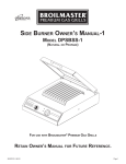
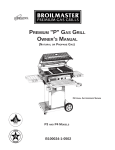
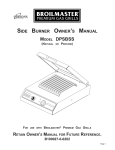
1
S5
SERIES GRILLS
(PROPANE GAS AND NATURAL GAS TYPES)
OWNER’S MANUAL
THESE GRILLS ARE FOR OUTDOOR USE ONLY.
IMPORTANT
READ THIS OWNER’S MANUAL CAREFULLY BEFORE INSTALLING OR USING THIS
PRODUCT. INSTALLER SHOULD LEAVE THIS MANUAL WITH THE CONSUMER AND THE
CONSUMER SHOULD RETAIN IT FOR FUTURE REFERENCE.
WARNING
IMPROPER INSTALLATION, ADJUSTMENT, ALTERATION, SERVICE OR
MAINTENANCE CAN CAUSE INJURY OR PROPERTY DAMAGE. REFER
TO THIS MANUAL. FOR ASSISTANCE OR ADDITIONAL INFORMATION
CONSULT A QUALIFIED INSTALLER, SERVICE AGENCY OR THE GAS
SUPPLIER.
FOR YOUR SAFETY
IF YOU SMELL GAS:
1. SHUT OFF GAS TO APPLIANCE.
2. EXTINGUISH ANY OPEN FLAME.
3. OPEN GRILL LID.
4. IF ODOR CONTINUES, IMMEDIATELY
CALL YOUR GAS SUPPLIER OR YOUR
FIRE DEPARTMENT.
FOR YOUR SAFETY
1. DO NOT STORE OR USE GASOLINE
OR OTHER FLAMMABLE VAPORS
AND LIQUIDS IN THE VICINITY OF
THIS OR ANY OTHER APPLIANCE.
2. AN LP CYLINDER NOT CONNECTED
FOR USE SHALL NOT BE STORED IN
THE VICINITY OF THIS OR ANY
OTHER APPLIANCE.
5. DO NOT TOUCH ELECTRICAL SWITCHES.
B100029-1-0502
S5
CONTENTS
INTRODUCTION. . . . . . . . . . . . . . . . . . . . . . . . . . . . . . . . . . . . . . . . . . . . . . . . . . . . . . . . . . . . . . . . . . . . . . . . . . . . . 2
SAFETY . . . . . . . . . . . . . . . . . . .
GAS. . . . . . . . . . . . . . . . . . . . .
GRILL LOCATION . . . . . . . . . .
ELECTRICAL ACCESSORIES .
.
.
.
.
.
.
.
.
.
.
.
.
.
.
.
.
.
.
.
.
.
.
.
.
.
.
.
.
.
.
.
.
.
.
.
.
.
.
.
.
.
.
.
.
.
.
.
.
.
.
.
.
.
.
.
.
.
.
.
.
.
.
.
.
.
.
.
.
.
.
.
.
.
.
.
.
.
.
.
.
.
.
.
.
.
.
.
.
.
.
.
.
.
.
.
.
.
.
.
.
.
.
.
.
.
.
.
.
.
.
.
.
.
.
.
.
.
.
.
.
.
.
.
.
.
.
.
.
.
.
.
.
.
.
.
.
.
.
.
.
.
.
.
.
.
.
.
.
.
.
.
.
.
.
.
.
.
.
.
.
.
.
.
.
.
.
.
.
.
.
.
.
.
.
.
.
.
.
.
.
.
.
.
.
.
.
.
.
.
.
.
.
.
.
.
.
.
.
.
.
.
.
.
.
.
.
.
.
.
.
.
.
.
.
.
.
.
.
.
.
.
.
.
.
.
.
.
.
.
.
.
.
.
.
.
.
.
.
.
.
.
.
.
.
.
.
.
.
.
.
.
.
.
.
.
.
3
3
4
4
ASSEMBLY AND INSTALLATION INSTRUCTIONS . . . . . . . . . . . . . . . . . . . . . . . . . . . . . . . . . . . . . . . . . . . . . . . . . . . 4
PREPARATION . . . . . . . . . . . . . . . . . . . . . . . . . . . . . . . . . . . . . . . . . . . . . . . . . . . . . . . . . . . . . . . . . . . . . . . . . . . . 4
GRILL ASSEMBLY AND INSTALLATION . . . . . . . . . . . . . . . . . . . . . . . . . . . . . . . . . . . . . . . . . . . . . . . . . . . . . . . . . 5
OPERATING INSTRUCTIONS . . . . . . . . . . . . . . . . . . . . . . . . . . . . . . . . . . . . . . . . . . . . . . . . . . . . . . . . . . . . . . . . . 10
IGNITOR LIGHTING PROCEDURE . . . . . . . . . . . . . . . . . . . . . . . . . . . . . . . . . . . . . . . . . . . . . . . . . . . . . . . . . . . . 10
MATCH LIGHTING PROCEDURE . . . . . . . . . . . . . . . . . . . . . . . . . . . . . . . . . . . . . . . . . . . . . . . . . . . . . . . . . . . . . 10
IF A BURNER DOES NOT IGNITE . . . . . . . . . . . . . . . . . . . . . . . . . . . . . . . . . . . . . . . . . . . . . . . . . . . . . . . . . . . . . 11
BREAK-IN . . . . . . . . . . . . . . . . . . . . . . . . . . . . . . . . . . . . . . . . . . . . . . . . . . . . . . . . . . . . . . . . . . . . . . . . . . . . . . . 11
PREHEAT . . . . . . . . . . . . . . . . . . . . . . . . . . . . . . . . . . . . . . . . . . . . . . . . . . . . . . . . . . . . . . . . . . . . . . . . . . . . . . . 11
COOKING . . . . . . . . . . . . . . . . . . . . . . . . . . . . . . . . . . . . . . . . . . . . . . . . . . . . . . . . . . . . . . . . . . . . . . . . . . . . . . . 11
MAINTENANCE . . . . . . . . . . . . . . . . . . . . . . . . . . . . . . . . . . . . . . . . . . . . . . . . . . . . . . . . . . . . . . . . . . . . . . . . . . . . 11
LOW FLAME ADJUSTMENT . . . . . . . . . . . . . . . . . . . . . . . . . . . . . . . . . . . . . . . . . . . . . . . . . . . . . . . . . . . . . . . . . 11
BURNER AIR ADJUSTMENT . . . . . . . . . . . . . . . . . . . . . . . . . . . . . . . . . . . . . . . . . . . . . . . . . . . . . . . . . . . . . . . . . 11
CARE AND CLEANING . . . . . . . . . . . . . . . . . . . . . . . . . . . . . . . . . . . . . . . . . . . . . . . . . . . . . . . . . . . . . . . . . . . . . 12
TROUBLESHOOTING . . . . . . . . . . . . . . . . . . . . . . . . . . . . . . . . . . . . . . . . . . . . . . . . . . . . . . . . . . . . . . . . . . . . . . 13
REPAIR PARTS AND WARRANTY. . . . . . . . . . . . . . . . . . . . . . . . . . . . . . . . . . . . . . . . . . . . . . . . . . . . . . . . . . . 14 - 18
INTRODUCTION
Congratulations! You have chosen the finest grill for your barbecuing pleasure. Please take the time to read through this
entire manual before assembling your Broilmaster® gas grill. Outdoor cooking is an art you will master.
Your Broilmaster® grill is identified by its model number, serial number, and gas type on a product identification label
located on the grill. Always reference the grill’s model number, serial number, and gas type when contacting your
Broilmaster® dealer. Record information from label here for easy reference.
Model Number:
Serial Number:
Gas Type: NATURAL
PROPANE
2
S5
SAFETY
Both NATURAL gas and PROPANE (also known as LP) gas have a long history of safe use when rules listed
below are followed. If they are not followed, there is a danger of fire, explosion or personal injury.
Installation must conform to local codes or, in the absence of local codes, with the National Fuel Gas Code ANSI
Z223.1. In Canada, installation shall be in accordance with CAN/CGA-B149.2 Propane Installation Code, or
CAN/CGA-B149.1 Natural Gas Installation Code, and local codes where applicable. Consult your local
NATURAL gas company or PROPANE gas dealer for code regulations and recommended procedures.
Never use PROPANE gas in a grill designed for NATURAL gas or NATURAL gas in a grill designed for
PROPANE gas. Please consult your local gas company for any questions about propane or natural gas.
Propane Gas Grills
On PROPANE gas grills, use only the PROPANE gas cylinder (tank) recommended or supplied. Broilmaster’s
PROPANE gas grills are for use with standard 20 pound PROPANE gas cylinders. DO NOT CONNECT A
BROILMASTER PROPANE GAS GRILL TO A PROPANE GAS CYLINDER EXCEEDING 20 POUNDS
CAPACITY. A cylinder of approximately 12-1/8” (30.8 centimeters) tall is the maximum size cylinder allowed.
The LP gas supply cylinder to be used must be:
1. constructed and marked in accordance with the specifications for LP gas cylinder of the U.S.
Department of Transportation (D.O.T.) or the National Standard of Canada, CAN/CSA-B339,
Cylinders, Spheres, and Tubes for Transportation of Dangerous Goods; and Commission as applicable.
2. provided with a listed overfilling prevention device;
3. provided with a listed safety device having direct access with the vapor space of the cylinder and
the cylinder supply system must be arranged for vapor withdrawal;
4. provided with a shutoff valve terminating in a valve outlet as specified in the Standard for
Compressed Gas Cylinder Valve Outlet and Inlet Connections, ANSICGA-V-1;
5. provided with a plug to effectively seal off the cylinder outlet when the cylinder is being stored or
transported;
6. provided with a collar to protect the cylinder valve.
Always use the pressure regulator and hose assembly supplied with each PROPANE gas grill. The pressure
regulator has an outlet pressure of not more than 11 inches water column and is to be connected to the
PROPANE gas cylinder’s female valve before the grill can be operated. Keep the pressure regulator’s fitting
clean and free of nicks and scratches. A dirty, nicked or scratched fitting can cause a gas leak, resulting in an
explosion or fire when connected to the PROPANE gas cylinder. Replacement parts must be as specified by
the repair parts list or as specified by Broilmaster.
CAUTION: OPERATION OF A PROPANE GAS GRILL WITHOUT THE PRESSURE REGULATOR AND
HOSE ASSEMBLY WILL CAUSE GAS LEAKS WHICH COULD CAUSE A FIRE, EXPLOSION OR
PERSONAL INJURY.
NOTE: SOME VALVE AND TANK COMBINATIONS ARE NOT COMPATIBLE. CHECK WARNING TAG ON
VALVE AND TANK; ALSO CHECK EXTERNAL THREADS OF FITTINGS. Broilmaster pressure regulator and
hose assemblies are equipped for cylinders with a Type 1 cylinder connection device.
Handle PROPANE gas cylinders with care:
A. If the cylinder’s outlet valve is damaged, do not attempt to use or repair. The cylinder must be replaced.
B. DO NOT store a grill indoors unless the PROPANE gas cylinder is disconnected and removed from the grill.
When the cylinder is installed on the grill they must be stored outdoors in a well-ventilated area.
C. Disconnected cylinders must have a threaded valve plug tightly installed and must not be stored in a build
ing, garage or any other enclosed space. KEEP OUT OF REACH OF CHILDREN.
D. Do not apply heat directly to a PROPANE gas cylinder.
E. Always transport, store and use PROPANE gas cylinders in an upright secure position.
F. DO NOT carry PROPANE gas cylinders in the passenger area of a vehicle.
G. For PROPANE gas grills, have PROPANE gas cylinders filled by a qualified gas dealer; cylinders are to be
filled by weight, to no more than 80% of physical capacity.
3
S5
Natural Gas Grills
NATURAL gas grills do not have a pressure regulator. Broilmaster Natural gas grills operate at a manifold
pressure of 7 inches water column.
For NATURAL gas grills, contact your local gas company to have a gas supply line installed for the grill. For
NATURAL gas grills installed on a cart, use Broilmaster’s NG12 twelve foot flexible hose and quick disconnect
kit to connect the grill to a pre-installed gas supply line.
All Grills
Check for gas leaks, after connecting a PROPANE gas cylinder, when a cylinder has not been used recently,
or when a grill is being used for the first time. Use soapy water to check for leaks. Refer to CHECKING FOR
LEAKS at the end of the Installation section.
CAUTION: DO NOT USE CANDLES, MATCHES OR OTHER IGNITION SOURCES WHEN CHECKING FOR
LEAKS. GASES ARE VERY FLAMMABLE AND, IN CERTAIN CONCENTRATIONS, EXPLOSIVE.
CHECKING FOR LEAKS WITH AN OPEN FLAME MAY LEAD TO FIRE, EXPLOSION OR PERSONAL
INJURY.
DO NOT use grill until all leaks are repaired. Always turn gas OFF at the valve on the PROPANE gas cylinder
or, for NATURAL gas, at the supply line shutoff valve when grill is not in use.
Inspect grill’s hose before each use of the grill. If there is excessive wear, or the hose is cut, it must be replaced.
Replace only with the hose assembly specified by the repair parts list or as specified by Broilmaster.
GRILL LOCATION
This grill was designed for outdoor use and should not be used in any building, garage or other enclosed area,
nor is it intended for use in or on any recreational vehicle or boat.
Never use the grill under combustible materials. (carport, covered porch, patio umbrella, etc.)
Minimum clearance from sides of grill to combustible materials (walls, fences, etc.) must be at least 16 inches.
Minimum clearance from back of grill must not be less than 18 inches.
CAUTION: IF THIS GRILL IS INSTALLED AND OPERATED AT CLEARANCES LESS THAN THOSE
SPECIFIED BY THESE INSTRUCTIONS, THE POSSIBILITY OF A FIRE, PROPERTY DAMAGE OR
PERSONAL INJURY MAY EXIST.
CAUTION: DO NOT INSTALL OR USE THIS GRILL IN ANY AREA WHERE EXPLOSIVE MATERIALS SUCH
AS GASOLINE OR OTHER FLAMMABLE VAPORS AND LIQUIDS ARE BEING USED OR STORED, THE
FLAME PRODUCED BY THE GRILL IS EXPOSED AND FLAME CONTACT WITH ANYTHING EXPLOSIVE
OR FLAMMABLE WILL RESULT IN EXPLOSION OR FIRE.
Keep area around grill clear. Do not obstruct grill’s combustion and ventilation air flow.
Keep the ventilation opening(s) of the cylinder enclosure free and clear of debris.
Make sure grill is level prior to use.
ASSEMBLY AND INSTALLATION INSTRUCTIONS
All Broilmaster grills require some assembly and installation. Some models require more than others. Some of the following
assembly and installation instructions do not pertain to all grill models. Some grill models come equipped with accessories
(i.e. side burner, cart, etc.) which were assembled and installed at the factory. Some grill models come with accessories
(i.e. cart) which are ready to be assembled and installed. Follow the instructions provided with the accessory to complete
it’s installation on a specific grill model.
PREPARATION
1. Before assembling the grill determine which post or cart the grill will be mounted on. See the enclosed “GRILL
MOUNTING” sheet for mounting options. Obtain and assemble the desired mount (post or cart) per instructions
furnished with it.
NOTE: If grill is to be mounted on an in-ground post, the post shall be protected against corrosion as warranted by
soil conditions. Corrosion protection shall be provided as needed with a suitable coating to retard the effects of
corrosion conditions existing in local areas.
4
S5
2. Gather the following items. They will be needed for grill assembly and installation.
Phillips Screwdriver
Two adjustable wrenches or a set of open end wrenches or a socket/ratchet set
Soapy water solution (to test for gas leaks)
Pencil (to check off steps as completed)
3. Remove all loose parts from inside the grill carton and grill housing which are to be assembled and installed.
GRILL ASSEMBLY AND INSTALLATION
1. If the grill is to be mounted on a cart, assemble the cart as shown in figure 1A & 2 with #10-3/8" sheet metal screws.
2. Attach the valve to the control panel with two No. 10-24 x 1/2" Phillips head screws. See figure 2A.
A. Push the gas knobs onto valve stems as shown by figure 2A. Turn knobs clockwise to OFF.
B. If the grill is furnished with a pushbutton ignitor, insert the ignitor into the ignitor hole of the control panel and then
secure it to the control panel with a nut as shown by figure 4.
3. Install the Piezo Ignitor
A. If your grill is furnished with an ignitor, assemble the ignitor’s collector box as shown by figure 5.
Caution: do not cut or damage the ignitor wire protruding from the collector box.
B. Install the collector box in the grill bottom thru the 15/32 hole located toward the front of the grill as shown in figure
5A. Flat washer, lock washer, 2 nuts align control panel with casting front and tighten nuts. See step 5 in Patio Base
Instructions to hook up gas.
4. Insert 10-24 x 3/4 bolt through 7/32" dia. hole located right of center towards rear of grill bottom. Attach speed nut and
tighten. See figure 6.
5. Install Control Panel. Post Models Only.
A. For post models, route two 1/4-20 x 1-1/2" screws install flat washer, lock washer and nuts through two holes in
bottom of the grill bottom and the top of the control panel. Align control panel with casting front and tighten nuts.
See figure 3. See step 5 in Patio Base instructions for gas hook up.
6. Mount the grill per Figure 1 or Figure 2A.
A. If the grill is to be mounted on a post, mount the grill bottom to the prepared post assembly so the eyebolts will
protrude through the holes at the corners of the rectangular opening in the grill bottom. Secure the grill bottom with
four 1/4 shakeproof washers and four 1/4-20 hex nuts. See figure 1.
B. For cart models, install the control panel between the cart angle brackets, and grill bottom. align holes. Insert four
1/4-20 x 1-1/2" screws, install flat washer, lock washer and 1/4-20 nut, then tighten. See figure 2A.
7. Attach the lid handle to grill lid using two No. 10-24 x 3 1/2" carriage bolts, two handle spacers, two shakeproof washers
and two No. 10-24 hex nuts. See figure 1 for cart installation.
8. Mount the grease tray as shown in figure 6. See Patio Base instructions for base installation.
A. Use the #10-24 wing nut and 5/8" O.D. flat washer to attach the grease tray bracket to the screw installed in step 4.
Do not tighten wing nut yet.
B. Place the provided aluminum grease tray in the bracket and adjust the bracket to align the tray with the grill’s
grease drain hole in grill bottom.
C. Tighten the wing nut. When the grease tray is full replace with a new empty tray.
D. Mount grease cup assembly as shown in Patio Base Instructions (figure 6)
9. Attach side shelf, if included, using two 1/4-20 x 1/2" hex bolts, 1/4 I.D. lock washers, and 1/4-20 hex nuts as shown
by figure 7. Use the #8 x 1/2” sheet metal screw and the 1/4" x 5/16" O.D. spacer to keep the wood shelf from sliding.
5
S5
FIGURE 1
FIGURE 1A
INSTALL FRONT SCREWS FIRST
GRILL TO POST
MOUNTING
CART ASSEMBLY
FIGURE 2
FIGURE 2A
CONTROL PANEL ASSY.
TO CART
CART
ANGLE BRACKETS
FIGURE 3
FIGURE 4
IGNITOR TO CONTROL PANEL
CONTROL PANEL ASSY. TO POST
6
S5
FIGURE 5
FIGURE 7
COLLECTOR BOX ASSEMBLY
SIDE SHELF ASSEMBLY
(S5 MODEL ONLY)
FIGURE 8
FIGURE 5A
BURNER
INSTALLATION
FIGURE 9
COLLECTOR BOX
INSTALLED
S5 MODEL
ONLY
VENTURI TUBE LOCATION
SPEED NUT
FIGURE 6
5/8 O.D. WASHER
GREASE CUP
INSTALLATION
7
S5
11. Install the burner as shown by figure 8 and figure 9.
A. Tilt the burner forward and guide its two venturi tubes through the rectangular hole in the bottom of the grill as shown
by figure 9. CAUTION: During installation of the burner, care should be taken to not damage the grill’s ignitor wire.
B. Push the ends of venturi tubes onto the corresponding factory-installed gas orifices located beneath the grill. See
figure 10.
C. Install ignitor wire, female end, by pushing it onto male ignitor, if equipped with piezo.
See Patio Base Instructions, step 8 for control housing installation.
12. Place the Briquet Rack in the grill bottom. See figure 10.
13. Spread the Briquets in a single layer evenly over the Briquet Rack. Do not overlap or stack briquet. There may be some
briquets left over. Save them for future use. See figure 10.
14. Put cooking grids in place in the grill bottom. The cooking grids can be independently placed in different positions for
different cooking heights above the Briquets. See figure 10.
15. Install Warming Rack as shown by figures 11, depending on your grill model.
16. If your grill is equipped with a side burner, the side burner has been factory-assembled and its gas hose has been
factory-connected to the grill. Mount the side burner on whichever side of the grill you choose and install two knobs on
the side burner. See figure 12.
A. Determine which side of the grill the side burner is to be mounted on.
B. Install the side burner’s mounting bracket. The side burner mounting bracket installs exactly like a side shelf mounting
bracket. See figure 7.
C. Lower the side burner onto the mounting bracket so that the side burner’s rear clamp is clamped around the back tube
of the mounting bracket as shown by figure 12.
D. Attach the front clamp to side burner and the front tube of the mounting bracket with two No. 10-24 x 3/8" screws, two
3/16” ID shakeproof washers, and two No. 10-24 nuts as shown by figure 12.
E. Push gas knob onto valve stem protruding through the side burner’s front panel as shown by figure 12. The knob will
fit only one way on the stem. After knob is on the stem, turn the knob to the OFF position if not already there.
F. Attach lid knob to the side burner’s lid with one 1/4-20 x 1/2" screw and one 1/2" OD shakeproof washer as shown by
figure 12.
Figure 13 shows a side burner mounted on the left side of a grill.
The side burner can be used to simmer, saute, boil or fry.
NOTE: PROPANE-gas grills can only be equipped with PROPANE - gas side burners and NATURAL-gas grills can only
be equipped with NATURAL-gas side burners.
17. Connect gas supply to grill per A or B below.
A. For PROPANE-gas grills:
1. Place properly filled PROPANE-gas cylinder in position and secure with the retainer provided.
2. Screw the grill’s regulator fitting onto the PROPANE - gas cylinder’s valve outlet male thread clockwise and tighten
securely.
NOTE: Regulator’s female fitting has right hand threads. Check fittings on tank and regulator, they may be different or
could be left hand threads. Vent on regulator must point down while the regulator is connected to the PROPANE - gas
cylinder.
3. The gas supply must be turned OFF at the PROPANE - gas cylinder when the grill is not in use.
B. For NATURAL - gas grills:
1. Arrange with local gas company to have a gas supply line installed for the grill.
2. If the grill is mounted on an in-ground post or patio base post, arrange with the local gas company to have the gas
supply line connected to the grill.
3. If the grill is mounted on a cart, obtain Broilmaster’s NG12 twelve-foot flexible hose and quick-disconnect kit to
connect the grill to the gas supply line installed by the local gas company. Connect the flexible hose to the grill
and gas supply line per the instructions furnished with the NG12 kit.
4. Always turn gas OFF at the gas supply line shutoff valve when a grill is not in use.
18. Check for gas leaks:
A. The appliance and its individual shutoff valve must be disconnected from the gas supply piping system during any
pressure testing of that system at test pressures in excess of 1/2 psi (3.5kPa).
B. The appliance must be isolated from the gas supply piping system by closing its individual manual shutoff valve during
any pressure testing of the gas supply piping system at test pressures equal to or less than 1/2 psi (3.5 kPa).
Check for gas leaks after connecting a PROPANE - gas cylinder to a grill, or when a cylinder has not been used for a
long time, or when a grill (PROPANE or NATURAL model) is being used for the first time or has not been used for
long time.
8
S5
FIGURE 11
FIGURE 10
S5 WARMING RACK
INSTALLATION
COOKING GRID
INSTALLATION
FIGURE 12
FIGURE 13
SIDE BURNER
INSTALLED
SIDE BURNER ASSEMBLY
FIGURE 14
LIGHTING INSTRUCTIONS
9
S5
Use soapy water to check for leaks.
DANGER: DO NOT USE CANDLES, MATCHES OR OTHER IGNITION SOURCES WHEN CHECKING FOR GAS
LEAKS. FUEL GASES ARE VERY FLAMMABLE AND, IN CERTAIN CONCENTRATIONS, EXPLOSIVE. CHECKING
FOR LEAKS WITH AN OPEN FLAME MAY LEAD TO FIRE OR EXPLOSION.
To check for gas leaks:
1. Use water and dish washing soap to make a soapy water solution.
2. Turn gas knobs located on grill’s control panel to OFF. Turn gas knob located on side burner’s control panel to
OFF.
3. For PROPANE - gas grills, turn gas ON at PROPANE - gas cylinder. For NATURAL - gas grills, turn gas ON at gas
supply line shutoff valve. (A hissing sound indicates a leak: Turn OFF gas supply, repair leak, turn ON gas supply
and proceed.)
4. Apply the soapy water solution to all gas connections.
5. Look for bubbles. Bubbles indicate gas leaks.
6. If bubbles are detected, turn gas OFF and tighten or repair leaking gas connections.
7. Turn gas ON and recheck for leaks. All gas connections must be leak-free.
8. For PROPANE - gas grills, turn gas OFF at PROPANE - gas cylinder until ready for use. For NATURAL - gas grills,
turn gas OFF at gas supply line shutoff valve until ready for use.
OPERATING INSTRUCTIONS
Before lighting a grill’s burner, make sure its venturi tubes are properly positioned on the gas orifices as described earlier
and as shown by figure 9. Check for gas leaks as described earlier.
Burners may be lit by ignitor or wooden match as described below. Light one burner at a time and light only the burners
needed.
Avoid moving a portable grill when the gas is turned on and a burner is lit.
IGNITOR LIGHTING PROCEDURE
Turn all gas knobs on the grill and side burner clockwise to OFF, then turn gas on at source and light the desired
burners as described below.
To light the grill’s double burner:
1. Raise the grill lid.
2. Push in and turn either the left gas knob or the right gas knob counterclockwise to HI.
3. If the grill’s ignitor is a pushbutton type, push the ignitor three or four times until the chosen section of the double burner
ignites; ignition should occur within about five seconds.
4. After the first section of the double burner is lit, ignite the other section by pushing in and turning its gas knob
counterclockwise to HI; ignition should occur automatically within about five seconds.
NOTE: Both sections of the double burner may be lit simultaneously by pushing in and turning both gas knobs to HI and
then operating the ignitor three or four times as described by step 3 above; ignition should occur within about five seconds.
If your grill was not furnished with an ignitor and you decide you want one for your grill, you may order an ignitor kit from
your Broilmaster dealer: Just read the lighting instructions on your grill’s control panel label to determine which type of
ignitor kit to order, then ask your Broilmaster dealer for pushbutton ignitor kit B056596.
To light the side burner:
1. Raise the side burner lid.
2. Push in and turn the side burner’s gas knob counterclockwise to HI.
3. Push the side burner’s ignitor three or four times until the side burner ignites; ignition should occur within about five
seconds.
NOTE: If a burner fails to ignite within five seconds, turn that burner’s gas knob clockwise to OFF, wait five minutes for the
gas to clear, then reattempt the ignitor lighting procedure or light with a wooden match as described by the following
MATCH LIGHTING PROCEDURE.
MATCH LIGHTING PROCEDURE
Turn all gas knobs on the grill and side burner clockwise to OFF, then turn gas on at source and light the desired
burners as described below.
To light the grill’s double burner:
1. Raise the grill lid.
2. Light a long wooden match and insert it through lighter hole in either side of the grill (which lighter hole depends on which
section of the burner is being lit). See figure 14.
3. Push in and turn the corresponding gas knob on the grill’s control panel counterclockwise to HI. That section of the burner
should ignite within about five seconds.
4. Light the other section of the burner by pushing in and turning the outer gas knob on the grill’s control panel
counterclockwise to HI. That section of the burner should ignite automatically within about five seconds.
10
S5
To light the side burner:
1. Raise the side burner lid.
2. Light a long wooden match and place its lit end against side of burner.
3. Push in and turn the side burner’s gas knob counterclockwise to HI; the burner should ignite within about five seconds.
IF A BURNER DOES NOT IGNITE
1. Turn that burner’s gas knob clockwise to OFF.
2. Wait five minutes for the gas to clear before again attempting to ignite that burner.
3. If the burner still does not ignite, turn that burner’s gas knob clockwise to OFF and refer to the TROUBLESHOOTING
section of this manual for solutions to the problem.
BREAK- IN
Before cooking on a new grill for the first time, break it in to get rid of fumes and oil from the manufacturing process.
1.
2.
3.
4.
5.
Raise grill lid.
Ignite grill burner (both sides).
Burn on HI for ten minutes with grill lid open.
Close grill lid and burn on HI for an additional ten minutes.
Grill is ready for cooking, or the burner may be turned off.
PREHEAT
Before cooking on a grill, always preheat it for at least five minutes on HI burner setting with its grill lid closed. This gives
the briquets time to heat up in the gas flames. Hot briquets cause better, quicker cooking and better flavor.
CAUTION: DO NOT LEAVE THE GRILL PREHEATING ON HI BURNER SETTING WITH THE GRILL LID CLOSED
FOR LONGER THAN 30 MINUTES.
NOTE: NEVER OPERATE THE SIDE BURNER WITH ITS LID CLOSED.
COOKING
A cookbook is provided with each new grill. The cookbook contains helpful cooking tips and instructions as well as great
recipes which tell exactly how to prepare many delicious foods on a Broilmaster grill.
MAINTENANCE
LOW FLAME ADJUSTMENT
Low flame setting for the burners is preset at factory. To adjust the flame height up or down at the lowest valve setting.
1. Light the burner on HI setting.
2. Turn the burner’s gas knob to LO setting.
3. Remove the gas knob and locate screw in center of the hollow valve stem.
4. Use a small screwdriver to turn the screw counterclockwise for a higher flame or clockwise for a lower flame.
CAUTION: If flame is adjusted to low, a strong wind condition could blow out the flame. The flame’s maximum height
(see A of figure 15) at LO valve setting should be no more than 1-1/2".
5. Put gas knob back on the valve stem after adjustment is complete.
BURNER AIR ADJUSTMENT
Venturi air shutters on grill burners are preset at the factory so that after five minutes of operation the burner flames
should be blue with well-defined cones. However, if after five minutes of operation, the burner flame is yellow or there is
a gap between the burner and flame, adjust the burner’s venturi air shutter as follows:
1.
2.
3.
4.
Turn gas OFF and let burner cool.
Loosen venturi air shutter’s set screw figure 16.
Close the venturi by rotating the air shutter (figure 16) to the minimum air opening.
Light the burner, wait five minutes and then carefully open the venturi air shutter until the burner flame is blue with welldefined cones.
5. Tighten the venturi air shutter’s set screw (figure 16).
NOTE: Other causes for a yellow flame are spider webs in venturi, seasoning salts on burner, and oil film on burner.
See the TROUBLESHOOTING section of this manual for solutions.
11
S5
CARE AND CLEANING
1. COOKING GRID: Wipe with paper towels immediately after cooking and while grease is hot. DO NOT use a
commercial oven cleaner. Brush with brass bristle brush (available as accessory #DPA21). DO NOT use steel wire
brush.
2. BURN OFF: After each use of grill - A. Turn gas knob to HI.
B. Close grill lid and allow grill to burn for 10 minutes or until smoke no longer comes from grill.
CAUTION: A flare-up may occur if grill lid is opened.
C. Turn gas knob to OFF and allow grill to cool.
3. INSIDE AIR HOLES: Periodically, remove grids, briquet rack, and clean. COVER orifice openings with aluminum foil
and scrape accumulations inside grill with a putty knife. Clean bottom air holes with small knife. Rinse with water.
4. BURNER MAINTENANCE: Stainless steel burners often oxidize to a reddish brown color. This will not affect
performance. At least twice a year, remove and clean burners with a brass - not steel - brush and a mild detergent.
Spiders and other small insects can build webs or nests in the venturi tubes of a grill’s burner and obstruct the gas
flow. A fire in and around the venturi tubes could occur because of the obstruction, This type of fire, known as
flashback, could damage components located beneath the grill and create an unsafe operating condition. To reduce
chances of flashback, frequent inspection and cleaning inside the venturi tubes is necessary. Cleanings are
recommended at least twice a month during late summer and early fall when spiders are most active; cleaning is also
recommended if the grill has not been used in a long while. To clean the venturi tubes, remove them and flush them
out with water, then use a wire or a small flexible bottle brush to remove any debris which was not flushed out by the
water. Allow the tubes to dry before reinstalling. If the grill is equipped with a side burner, its burner should also be
removed along with the grill’s venturi tubes and cleaned too in the same manner as the grill’s venturi tubes. If flashback
ever does occur, turn the gas knobs to their OFF position and turn off source of gas; wait until the burners cool, then
remove and clean accordingly as described above. Check for damage and make any necessary repairs before using
the grill or side burner again.
5. EXTERIOR: Clean regularly with a solution of mild detergent and hot water . Touch-Up paint (accessory number
DPA18) is available from your Broilmaster dealer. Protective vinyl covers are also available and recommended.
6. BRIQUETS: If they are not cleaned after a burn-off, wait until they cool and turn them over. The next time your use
your grill, the residue will burn off during normal warm-up.
FIGURE 15
FIGURE 16
FLAME HEIGHT
AIR SHUTTER ADJUSTMENT
12
S5
TROUBLESHOOTING
While the manufacturer has made every reasonable effort to insure that these grills operate properly and satisfactorily,
sometimes problems do arise. The following troubleshooting chart lists several possible problems with their probable cause
and solution.
PROBLEM
GRILL’S
BURNER
WON’T
LIGHT
GRILL NOT HOT
ENOUGH
FLAME BLOWS
OUT ON LO
YELLOW FLAME
CAUSE
SOLUTION
1. Misalignment of burner/venturi
on orifice.
Reposition venturi opening to make sure it is properly
positioned on the orifice.
2. Plugged orifice.
Remove orifice from gas control assembly and clean.
Turn gas knob to HI for 1 second only to blow out any
debris which might be in gas valve. Turn gas knob to
OFF and reinstall the orifice.
3. Obstruction in gas line.
For propane models, make sure gas valve on cylinder is
OFF. Remove the flexible hose and blow out any dirt.
4. Spider webs in venturi tubes.
Clean venturi tubes (see instructions).
5. Misalignment of collector box
and burner.
Check for proper positioning of electrode and clean
collector box.
6. Out of gas.
Refill propane-gas cylinder. If natural model, turn on gas
at source.
1. Poor combustion.
Air shutter needs adjusting.
2. Misalignment of burner/venturi
on orifice.
See 1 under “Grill’s Burner Won’t Light” above.
3. Inadequate gas pressure.
Have gas company check.
1. Cold grill.
Allow grill to preheat at least 5 minutes on HI with the
grill lid closed before turning to LO.
2. Misalignment of burner/venturi
on orifice.
See 1 under “Grill’s Burner Won’t Light” above.
3. Poor combustion.
Air shutter needs adjusting.
4. Low flame setting
Turn low flame setting higher.
5. Extreme wind.
Turn or shield grill.
1. Air shutter improperly set.
Open air shutter (see instructions).
2. Spider webs in venturi.
Clean venturi tubes (see instructions).
3. Seasoning salts on burner.
Clean and wash burner with mild detergent.
4. Oil film on burner.
Allow burner to operate 10-15 minutes at HI.
13
S5
REPAIR PARTS
See figures 18 for CP Grill repair parts. Order all repair parts from your Broilmaster dealer. To help ensure prompt and
accurate filling of orders, please supply the following information when placing a repair order:
1. MODEL NUMBER OF CART
2. PART NAME
3. PART NUMBER
4. QUANTITY OF PARTS NEEDED
FIGURE 17
ASSEMBLY OF CART
FOR CP GRILLS
KEY
NO.
1
2
3
4
5
6
7
8
9
10
11
12
13
14
15
16
PART NAME
Pedestal Cart Ptd.
Base Cylinder Shelf Ptd.
Axle 17"
Plastic Wheel 7"
Hub Cap
Foot Cart
#10 x 3/8" Screw
Rear Cart Brace Ptd.
1/4 - 20 x 1-1/4 Screw
1/4 x 5/8" Lock Washer
1/4 - 20 Hex Nut
Cylinder Retainer Assembly
1/4 - 20 Wing Nut
Bracket Ped/Grill (Left)
Bracket Ped/Grill (Right)
Rubber Grommet
14
QTY.
PER CART
S5 CP
PART NO.
1
1
1
2
2
1
20
1
1
1
1
1
1
1
1
3
B057825
B057819
B058124
B100095
B100108
B058619
B053779
B057812
B100114
B100139
B100120
B064791
B100126
B057815
B057816
B100103
S5
FIGURE 18
6
ASSEMBLY OF GRILL
HOUSING FOR CP AND NWO GRILLS
15
S5
ITEM
NO.
DESCRIPTION
1
2
3
4
6
7
8
9
10
10
11
11
12
13
14
15
16
17
18
19
19
20
21
21
22
23
24
25
26
27
28
29
30
31
32
33
34
35
Lid Casting Ptd.
Bottom Casting Ptd.
Hinge Pin
Bridge Pin
10-24 Keps Nut
Standoff Lid Handle
10-24 x 3 1/2 Carriage
Lid Handle
1/4 x 5/8 Lock Washer
1/4 x 5/8 Lock Washer
1/4 - 20 Hex Nut
1/4 - 20 Hex Nut
1/4 - 20 x 1-1/2 Hex Bolt
Wood Side Shelf
Pull Handle Bracket
10 - 24 x 1 Screw
10 - 24 Wing Nut
Grease Tray Bracket
Grease Tray
1/4 - 20 x 1-1/4
1/4 - 20 x 1-1/4
#10 - 24 Speed Nut
9/32 ID X 5/8 Washer
9/32 ID X 5/8 Washer
45° Copreci Valve
Hose & Regulator
Control Panel Assembly w/Label
Control Panel Label (Not Shown)
Ignitor (Pushbutton)
Valve Knob
10 - 24 x 3/8 Screw
Burner Assembly
Collector Box Assembly
Warming Rack
Briquet Rack
Ceramic Briquets
Cooking Grids
#8 x 1/2 Screw
Handle Spacer
QTY.
S5CP
S5NWO
1
1
2
2
2
2
2
1
7
2
7
2
2
1
1
1
1
1
2
4
2
1
5
3
1
1
1
B100062
B100063
B057804
B057805
B073967
B059271
B059273
B060312
B100139
B100062
B100063
B057804
B057805
B073967
B059271
B059273
B060312
B100139
B100120
B100112
B060324
B053783
B100138
B100125
B060336
B060337
B100114
B100121
B100136
B069751
B069756
B100188
B058123
B885160
B070084
B100137
B053791
B056482
B878363
B070404
B058122
B878361
B100140
B662325
1
2
2
1
1
1
1
1
1
1
1
B100120
N/A
N/A
N/A
B100138
B100125
B060336
B060337
B100114
B100121
B100136
B069750
N/A
B100188
B058123
N/A
B070084
B100137
B053791
N/A
B878363
B070404
B058122
B878361
N/A
N/A
REPAIR PARTS AND WARRANTY
Periodic inspections and maintenance are essential. All Gas Grill products eventually begin to wear due to environment,
contaminants, erosion or aging or components made of metal or rubber. Inspect all components at least two times per
year and replace when necessary.
A repair parts pamphlet is provided with this manual. When placing a repair part order with your Broilmaster dealer, refer
to the pamphlet for repair part information.
A warranty is provided with this manual. For warranty claims, follow the instructions provided by the warranty.
SAVE THIS MANUAL FOR FUTURE REFERENCE.
16
S5
WARRANTY
LIMITED WARRANTY
Manufactured in U.S.A. by Broilmaster, a Division of Empire Comfort Systems, Inc., P.O. Box 529,
Belleville, Illinois 62222.
WHAT IS COVERED AND FOR HOW LONG.
From the date this grill is first purchased for use, Broilmaster will make available, at our factory, a
free replacement for any defective part covered by this warranty on the following basis:
LIMITED LIFETIME WARRANTY
• Aluminum Grill Housing
• Stainless Steel Burners
• Stainless Steel Carts
• Stainless Steel Carts and/or Mountings
• Side Burner & Housing
• Porcelain Coated Cast Iron Cooking Grids (Damaged by dropping, scraping or abrasive cleaning
voids the warranty for the cooking grids)
• Stainless Components for Built-in Series (BIKH, BIKSB, BIKBIN, BIKDR)
LIMITED 5-YEAR WARRANTY
• Painted Electrogalvanized Steel Components
LIMITED 2-YEAR WARRANTY
• Porcelain Coated Steel Cooking Racks
• All Other Parts
LIMITED 1-YEAR WARRANTY
• Rotisserie Units
• Premium Tool Set
• Grill Covers
• Shelving
17
S5
WARRANTY
WHAT IS NOT COVERED
• Removal and reinstallation cost.
• Labor for replacement or repairs.
• The costs of a service call to diagnose a problem.
• Transportation and shipping cost.
• Finishes on surface that are damaged by
improper installation, improper storage, accident, misuse, abuse or alteration.
• Inoperable due to improper or lack of cleaning.
• Damage from accident, misuse, alteration, abuse, improper installation or storage.
This warranty does not imply or assume any responsibility for consequential damages that might
result from use, misuse, or improper installation of this cooking appliance.
This warranty does not cover claims, which do not involve defective workmanship or materials.
A bill of sale, cancelled check, or payment record should be kept to verify purchase date and
establish warranty period.
HOW TO GET SERVICE
Service under this warranty must be obtained by contacting your Broilmaster dealer. (See telephone
directory or call 800-851-3153, Consumer Relations Department, Empire Comfort Systems, Inc.)
Provide the dealer with Model number, Serial number, type of gas and purchase verification
information.
YOUR RIGHTS UNDER STATE LAW
This warranty gives you specific legal rights, and you may also have other rights, which vary from
state to state.
This warranty applies only to the original purchaser and may not be transferred. This warranty
applies as long as the grill can be used safely as a residential gas grill.
BROILMASTER®
A Division of Empire Comfort Systems, Inc.
918 Freeburg Ave.
Belleville, Illinois 62220
Phone: 1-800-851-3153
FAX: 1-800-443-8648
Visit our web site at www.broilmaster.com
This warranty gives you specific legal rights, and you may also have other rights which vary from state to state.
18
S5
BROILMASTER®
A Division of Empire Comfort Systems, Inc.
918 Freeburg Ave.
Belleville, Illinois 62220
Phone: 1-800-851-3153
FAX: 1-800-443-8648
Visit our web site at www.broilmaster.com
B100029-1-0502
19
S5