1
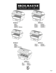
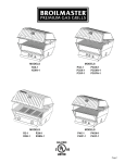
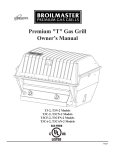
PREMIUM "P" GAS GRILL
OWNER’S MANUAL
(NATURAL
OR
PROPANE GAS)
OPTIONAL ACCESSORIES SHOWN
P3
AND
P4 MODELS
B100024-1-0502
P3, P4
Page 1
IMPORTANT
THIS MANUAL SHOULD BE READ THOROUGHLY BY THE PERSON INSTALLING THE GRILL AND ALL PERSONS
THE INSTALLER SHOULD BE SURE THE MANUAL IS LEFT IN THE
POSSESSION OF THE USER. THE USER SHOULD RETAIN THIS MANUAL FOR FUTURE REFERENCE WHEN
USING OR CLEANING THE GRILL AND TO PROPERLY IDENTIFY ANY REPAIR PARTS THAT MAY BE REQUIRED.
WHO WILL USE AND MAINTAIN THE GRILL.
WARNING
REFERENCE
THIS MANUAL FOR PROPER INSTALLATION AND MAINTENANCE INSTRUCTIONS.
IMPROPER
INSTALLATION, ADJUSTMENT, ALTERATION, SERVICE OR MAINTENANCE CAN CAUSE PERSONAL INJURY OR
PROPERTY DAMAGE.
FOR ASSISTANCE OR ADDITIONAL INFORMATION CONSULT A QUALIFIED INSTALLER,
SERVICE AGENCY OR THE GAS SUPPLIER.
CAUTION: FOR YOUR SAFETY
IF YOU SMELL GAS:
1.
2.
3.
4.
SHUT OFF GAS TO THE APPLIANCE.
EXTINGUISH ANY OPEN FLAME.
OPEN THE GRILL LID.
IF ODOR CONTINUES, IMMEDIATELY CALL
FIRE DEPARTMENT.
5. DO NOT TOUCH ELECTRICAL SWITCHES.
YOUR GAS SUPPLIER OR
CAUTION: FOR YOUR SAFETY
1. DO NOT STORE OR USE GASOLINE OR OTHER FLAMMABLE VAPORS AND LIQUIDS IN THE VICINITY OF
THIS OR ANY OTHER APPLIANCE.
2. AN LP CYLINDER NOT CONNECTED FOR USE SHALL NOT BE STORED IN THE VICINITY OF THIS OR ANY
OTHER APPLIANCE.
CAUTION:
PARTS
MAY HAVE SHARP EDGES.
WEAR
LEATHER WORK GLOVES AND HANDLE PARTS CAREFULLY
DURING THE UNPACKING, ASSEMBLY AND INSTALLATION.
WARNING
BROILMASTER® GAS GRILLS MUST ONLY USE PROPANE CYLINDERS EQUIPPED WITH AN OVERFILL
PROTECTION DEVICE (OPD). USE ONLY A REPUTABLE PROPANE DEALER WHEN EXCHANGING OR FILLING
CYLINDERS. AN OVERFILLED OR IMPROPERLY FILLED PROPANE CYLINDER CAN BE DANGEROUS.
Page 2
P3, P4
Congratulations!
Welcome to the beauty, durability, and prestige of a
PREMIUM GAS GRILL by BROILMASTER®. With award-winning
excellence built into every feature and durability that
surpasses other premium gas grills, BROILMASTER has
manufactured the ultimate gas grill for discriminating
outdoor chefs for over 30 years.
At Broilmaster, we continually strive to enhance the
performance and quality of our products for your grilling
enjoyment. Every effort will be made to ensure that
Broilmaster continues to be your choice as the premium grill
of the future.
Whether you are at the lake or in the privacy of your own
backyard, the BROILMASTER® PREMIUM GAS GRILL performs
far beyond the ordinary and is designed to provide your
family with years of outdoor cooking pleasure.
Thank You!
Broilmaster® is a registered trademark of
Empire Comfort Systems, Inc.
918 Freeburg Ave.
Belleville, Illinois 62220
Telephone 800-851-3153
P3, P4
Page 3
TABLE
OF
CONTENTS
C ONGRATULATIONS !
You have chosen the finest grill for your outdoor cooking pleasure. Please take time to read
this entire manual before assembling your premium Broilmaster® gas grill.
Parts
Diagram .............................................................................................................................. 5
List ...................................................................................................................................... 6
Grill Assembly ............................................................................................................... 7-11
Propane Gas Grills ...................................................................................................... 12-14
Gas Conversion ............................................................................................................... 15
Natural Gas Grills ............................................................................................................. 16
Operation- Propane & Natural Grills ........................................................................... 17-18
Maintenance ........................................................................................................................ 19
Troubleshooting................................................................................................................... 20
Notes ................................................................................................................................... 21
Warranty ......................................................................................................................... 22-23
Your Broilmaster® Premium Gas Grill is identified by model number, serial number, and
gas type. This information is provided on a product identification label located on the
grill’s control panel. For your convenience, complete this section for future reference
when contacting your dealer.
Model No.
Dealer
Serial No.
Dealer Phone No.
Gas Type: Propane
Page 4
Natural
Date of Purchase
P3, P4
PARTS DIAGRAM
All repair part orders should be placed through your local Broilmaster® dealer. To locate a dealer in
your area, contact Broilmaster Customer Service at 800-851-3153 • WWW.broilmaster.com. To ensure
prompt and accurate service, please provide the following information when placing a repair part
order: Model Number, Serial Number, Part Name, Part Number, and Quantity of parts needed.
P3, P4
Page 5
PREMIUM "P" SERIES PARTS LIST
KEY
NO.
1
2
3
4
5
6
7
8
9
10
11
11
11A
11A
11B
11B
11C
12
13
14
15
16
17
18
19
20
21
23
24
25
26
27
28
29
30
32
33
36
37
38
39
40
41
42
43
PART NAME
BRIDGE PIN
HINGE PIN
RETRACT-A-RACK
COOKING GRID
BRIQUETTE BAG
GRID LIFTER ASSEMBLY
HOSE & LP REGULATOR
GRILL BODY BOTTOM
LID STOP KNOB
LID STOP
CONTROL VALVE ASSEMBLY (LP)
CONTROL VALVE ASSEMBLY (NAT)
VALVE (LP)
VALVE (NAT)
MANIFOLD (LP)
MANIFOLD (NAT)
MOUNTING PLATE
NATURAL CAP ORIFICE *
GRILL BODY TOP
HEAT INDICATOR
HANDLE STAINLESS
FOAM GRIP
BRIQUETTE RACK
BURNER ASSEMBLY
COLLECTOR BOX ASSEMBLY
RADIATION SHIELD
COLLECTOR BOX SPACER
ELECTRONIC IGNITOR
IGNITOR GROUND LUG
IGNITOR GROUND WIRE
CONTROL PANEL ASSEMBLY W/LABEL
CONTROL PANEL LABEL (NOT SHOWN)
VALVE KNOB
KEPS NUT
SHELF PIN
CONVERSION LABEL *
SPACER
9/32 I.D. X 5/8 O.D. FLAT WASHER
#10-24 X 3/4 SCREW
3/8-16 X 1 1/2 SCREW
3/8 STAR WASHER
#10-24 X 1 SCREW
STABILIZER ARM **
STABILIZER BRACKET **
#10-24 X 3/8 SCREW **
10-24 WING NUT
P3BL
PART NO.
B057805
B057804
B072695
B743100
B058122
B064539
B069756
B076539
B100098
B076521
B070501
B070502
B076790
B076789
B069002
B069003
B064787
B056647
B076538
B076625
B070282
B073097
B063066
B878531
B072701
B063065
B069743
B072218
B069747
B072684
B100152
B072686
B070084
B073967
B073963
B100033
B662325
B076332
B076522
B100117
B100135
B073978
B906180
B905048
B100137
B100125
P3HG
PART NO.
B057805
B057804
B072695
B743100
B058122
B064539
B069756
B100146
B100098
B076521
B070501
B070502
B076790
B076789
B069002
B069003
B064787
B056647
B100147
B076625
B070282
B073097
B063066
B878531
B072701
B063065
B069743
B072218
B069747
B072684
B100152
B072686
B070084
B073967
B073963
B100033
B662325
B076332
B076522
B100117
B100135
B073978
B906180
B905048
B100137
B100125
P3GY
PART NO.
B057805
B057804
B072695
B743100
B058122
B064539
B069756
B100144
B100098
B076521
B070501
B070502
B076790
B076789
B069002
B069003
B064787
B056647
B100145
B076625
B070282
B073097
B063066
B878531
B072701
B063065
B069743
B072218
B069747
B072684
B100152
B072686
B070084
B073967
B073963
B100033
B662325
B076332
B076522
B100117
B100135
B073978
B906180
B905048
B100137
B100125
P4BL
PART NO.
B057805
B057804
B072696
B804687
B058122
B064539
B069756
B076622
B100098
B076521
B070501
B070502
B076790
B076789
B069002
B069003
B064787
B056647
B076621
B076625
B070486
B073097
B067449
B814801
B072701
B063065
B069743
B072218
B069747
B072684
B100153
B072197
B070084
B073967
B073963
B100033
B662325
B076332
B076522
B100117
B100135
B073978
B906180
B905048
B100137
B100125
P4HG
PART NO.
B057805
B057804
B072696
B804687
B058122
B064539
B069756
B100150
B100098
B076521
B070501
B070502
B076790
B076789
B069002
B069003
B064787
B056647
B100151
B076625
B070486
B073097
B067449
B814801
B072701
B063065
B069743
B072218
B069747
B072684
B100153
B072197
B070084
B073967
B073963
B100033
B662325
B076332
B076522
B100117
B100135
B073978
B906180
B905048
B100137
B100125
P4GY
PART NO.
B057805
B057804
B072696
B804687
B058122
B064539
B069756
B100148
B100098
B076521
B070501
B070502
B076790
B076789
B069002
B069003
B064787
B056647
B100149
B076625
B070486
B073097
B067449
B814801
B072701
B063065
B069743
B072218
B069747
B072684
B100153
B072197
B070084
B073967
B073963
B100033
B662325
B076332
B076522
B100117
B100135
B073978
B906180
B905048
B100137
B100125
* INCLUDED WITH PROPANE GRILLS ONLY.
** BURNER STABILIZER KIT IS INCLUDED WITH YOUR CART.
Page 6
P3, P4
GRILL ASSEMBLY
Before You Begin
Recommended Tools
All Broilmaster grills require some assembly and
installation. Follow all instructions unless noted
to apply only to other specific models.
These items are recommended for the assembly
of your grill:
If you purchased an accessory with your
Broilmaster, follow the instructions provided with
the accessory for assembly and installation. If
an instruction refers to a step that is not required
for your grill model, please continue to the next
step.
Each step of the installation is illustrated. In
each illustration parts are identified with “Key”
numbers. Key numbers appear in parenthesis
after a part name is mentioned for the first time in
the instructions and are labeled on the
illustrations. You can reference each part by its
key number on the Parts List if you need help in
identifying a part.
• Phillips screwdriver
• Adjustable wrench set
• Socket set
• Soapy water solution (to test for leaks)
• Liquid soap (for foam grip)
Grill Mountings
Assemble your base option before assembling
your Broilmaster® grill head.
Refer to the Broilmaster® Cart, Base, and Post
instructions provided with each accessory for
assembly, installation, and mounting procedures.
Compare the parts found in the shipping
container to the parts list provided. If any parts
are missing contact your Broilmaster® dealer
before beginning assembly.
CAUTION: FOR YOUR SAFETY
PARTS MAY HAVE SHARP EDGES. WEAR LEATHER WORK
GLOVES AND HANDLE PARTS CAREFULLY DURING THE
UNPACKING, ASSEMBLY AND INSTALLATION.
P3, P4
Page 7
GRILL ASSEMBLY
Igniter Assembly
FIGURE 5
19
Slide the collector box spacer (21) and nut
(provided on assembly) onto the collector box
shaft and tighten. FIGURE 5.
Note: Peel protective film from control panel
before installing igniter.
21
Nut
24
25
FIGURE 6
Installing the Igniter
-
AA ALKALINE
BATTERY
CAUTION: DO NOT CUT OR DAMAGE IGNITER WIRE.
+
Carefully thread the end of the igniter wire
through the center hole in the grill bottom. Slide
the ground lug (24) over the igniter wire and
fasten with nut provided.
GROUND
SPARK
Attach one end of the ground wire (25) to the
terminal on the rear of the electronic igniter.
Attach the remaining end to the ground lug.
FIGURES 5 AND 6.
24
Battery Installation: Slide the spring onto the negative end of the battery.
Drop the battery and spring into the igniter and replace the button.
Burner Stabilizing Arm
FIGURE 7
(Portable Cart Models Only)
On the burner assembly (18) remove the rear
screw, insert the burner stabilizing arm (40), and
reinstall the screw as shown. FIGURE 7.
Note: Burner Stabilizing Arm, Burner Stabilizing
Bracket, and Securing the Burner sections of this
manual apply only to portable cart models ONLY.
Hardware is packaged with your cart.
Page 8
Venturi
Tubes
40
18
P3, P4
GRILL ASSEMBLY
Burner Stabilizing Bracket
FIGURE 8
(Portable Cart Models Only)
Tip: Test the alignment of the burner stabilizing
brackets before tightening the burner stabilizing
bracket.
36
Install the burner stabilizing bracket (41) and
fasten with the 10-24 x 3/4 phillips screw and
10-24 wing nut.
FIGURE 9
41
8
Radiation Shield
Place the radiation shield (20) in the grill
bottom. FIGURE 9.
INSTALL THIS SIDE UP
20
19
Installing the Burner
FIGURE 10
Insert the burner assembly into the grill bottom with
the venturi tubes facing the front of the grill. FIGURE
10.
The gas jets from the control valve will be inside the
ends of the venturi tubes when properly installed.
FIGURE 11.
FIGURE 11
Air
Shutter
Venturi
Tube
P3, P4
Shutter Set
Screw
11
Page 9
GRILL ASSEMBLY
Securing the Burner
18
(Portable Cart Models Only)
Secure the burner by aligning the burner stabilizing
bracket and the burner stabilizing arm and
fastening with a screw (42) and a keps nut (28).
FIGURE 12.
41
42
28
FIGURE 12
FIGURE 13
Lid Stop
Attach the lid stop assembly to the grill bottom as
shown. FIGURE 13.
32
28
33
36
Handle
For your added comfort a foam grip (16) has been
provided. FIGURE 15.
Tip: For ease of installation, slightly lubricate the
front handle with liquid soap before pushing the
foam grip into place.
Fasten the stainless steel front handle (15) to the
grill lid (13) with two #10-24 x 1" screws (39).
FIGURE 14.
FIGURE 14
13
14
39
15
16
39
FIGURE 15
Page 10
P3, P4
GRILL ASSEMBLY
Installing Racks
Place the briquet rack on the burner assembly.
Position the ceramic briquets evenly on the
briquette rack without overlapping.
Set the multilevel cooking grids FIGURE 17.
4
FIGURE 17
5
17
Installing Char-Master
Briquets
Individually place the ‘Char-Master’ briquets in a
single layer evenly on your grill’s briquet rack;
DO NOT dump them onto the briquet rack. A
single layer of ‘Char-Master’ briquets is all that’s
needed. DO NOT overlap or stack the briquets.
See FIGURE 17.
After properly placing the ‘Char-Master’ briquets
on your grill’s briquet rack, there may be some
briquets left over. Save them for future use.
Before cooking, always preheat the grill as
directed by the grill’s operating instructions. Hot
briquets cause better, quicker cooking and
better flavor.
Cleaning
Routine preheating and routine burn-off (also
called postheating) of a grill will clean the ‘CharMaster’ briquets. Periodically turn the briquets
over while they are cool.
Grid Lifter
FIGURE 18
Assemble the grid lifter as shown. FIGURE 18.
When positioning or removing grids always use the
grid lifter provided with your grill.
37
P3, P4
38
37
38
Page 11
PROPANE GAS GRILLS
Grill Location
Gas Type
When choosing the ideal location for your
Broilmaster® Premium Gas Grill, remember this
grill is designed for outdoor use ONLY.
Never use Liquid Propane (LP) gas with a grill
designed for Natural gas, or Natural gas with a
grill designed for Liquid Propane gas. The type
gas required for your grill can be determined
from the product identification label located on
the grill’s control panel. Questions regarding
different types of gases should be directed to
your gas supplier.
You should never install or operate your grill in
any building, garage, or other enclosed area.
For your safety, this grill should not be installed
or operated under any combustible materials,
such as carports, covered porches, awnings, or
overhangs.
Never install or operate your grill in or on any
recreational vehicle or boat.
CAUTION: THE INSTALLATION AND OPERATION OF
THIS GRILL AT CLEARANCES LESS THAN SPECIFIED BELOW
MAY LEAD TO THE POSSIBILITY OF FIRE, PROPERTY
DAMAGE, OR PERSONAL INJURY.
A minimum clearance of sixteen (16") inches is
required from the sides of the grill to any
combustible material.
A minimum clearance of eighteen (18") inches is
required from the back of the grill to any
combustible material.
Some examples of combustible materials are a
wall, a fence, patio furniture, or the wall of your
home.
The area surrounding the grill should be clear to
ensure proper ventilation. Do not obstruct the
flow of combustion and ventilation air in any way.
The ventilation openings on the propane cylinder
enclosure must also remain free and clear of
debris.
Portable grills should be level and positioned
away from direct wind prior to each use.
WARNING: DO NOT INSTALL OR OPERATE THIS GRILL
WHERE GASOLINE OR OTHER FLAMMABLE MATERIALS ARE
USED OR STORED. FAILURE TO COMPLY WITH THIS
WARNING COULD RESULT IN EXPLOSION OR FIRE CAUSING
PROPERTY DAMAGE OR PERSONAL INJURY.
Page 12
Cylinder Requirements
YouR Broilmaster® Premium Gas Grill requires a
standard twenty (20) pound propane gas cylinder.
The maximum height allowable for a replacement
cylinder is approximately twelve (12") inches
(30.5 centimeters).
The propane gas cylinder used must be:
1. constructed and marked in accordance with the
specifications for LP gas cylinder of the U.S.
Department of Transportation (D.O.T.) or the
National Standard of Canada, CAN/CSA-B339,
Cylinders, Spheres, and Tubes for Transportation
of Dangerous Goods; and Commission as
applicable.
2. provided with a listed overfilling protection device
(OPD).
3. provided with a listed safety device having direct
access with the vapor space of the cylinder and
the cylinder supply system must be arranged for
vapor removal.
4. provided with a shutoff valve terminating in a
valve outlet as specified in the Standard for
Compressed Gas Cylinder Outlet and Inlet
Connections, ANSICGA-V-1.
5. provided with a plug to effectively seal off the
cylinder outlet when the cylinder is being stored
or transported.
6. provided with a collar to protect the cylinder valve.
CAUTION: DO NOT USE A PROPANE GAS CYLINDER
WHICH HAS A CAPACITY GREATER THAN TWENTY (20)
POUNDS WITH THIS GRILL AND SIDE BURNER.
P3, P4
PROPANE GAS GRILLS
Propane Cylinder Safety
Connection Requirements
Liquid Propane (LP) gas has a long history of
safe use when the safety precautions provided
in this manual are followed.
CAUTION: NEVER USE LIQUID PROPANE (LP) GAS IN
A GRILL DESIGNED FOR NATURAL GAS, OR NATURAL
GAS IN A GRILL DESIGNED FOR LIQUID PROPANE GAS.
QUESTIONS REGARDING DIFFERENT TYPES OF GASES
SHOULD BE DIRECTED TO YOUR LOCAL GAS SUPPLIER.
FAILURE TO FOLLOW THESE SAFETY PRECAUTIONS
COULD RESULT IN A FIRE OR EXPLOSION CAUSING
PROPERTY DAMAGE OR PERSONAL INJURY.
Propane gas cylinders should always be
handled, stored, and transported with extreme
caution in a secured upright position.
Never attempt to use or repair a propane gas
cylinder that has been damaged. Never attempt
to use or repair a cylinder with a faulty or
damaged valve outlet. A cylinder that has been
dropped, dented, or otherwise damaged must
be replaced.
A propane gas cylinder should never be
transported in the passenger area of a vehicle.
Installation must conform to local codes or, in the
absence of local codes, with the National Fuel
Gas Code, ANSI Z223.1. In Canada, installation
shall be in accordance with CAN/CGA-B149.2
Propane Installation Code, or CAN/CGA-B149.1
Natural Gas Installation Code, and local codes
where applicable. Consult your local gas
supplier or propane gas dealer for code
regulations and recommended procedures.
WARNING: BROILMASTER® PREMIUM GAS GRILLS
REQUIRE LIQUID PROPANE (LP) CYLINDERS EQUIPPED
WITH AN OVERFILL PROTECTION DEVICE (OPD). AN
OVERFILLED OR IMPROPERLY FILLED PROPANE
CYLINDER CAN BE DANGEROUS.
Keep cylinders out of direct sunlight and never
apply any other source of direct heat to them.
Always use the pressure regulator and hose
assembly supplied with your Propane gas grill.
When refilling your cylinder, always insist on a
reputable, qualified gas dealer. Your propane
gas cylinder is filled by weight, and should
never exceed eighty (80%) percent of its weight
limit. If the cylinder is not completely empty, the
gas dealer must make necessary adjustments
to ensure it is not overfilled. Never use an
overfilled Propane gas cylinder.
Note: Not all valve and cylinder combinations are
compatible. Check warning tag on valve and
cylinder as well as external fitting threads.
Cylinder Storage
All Broilmaster® pressure regulators and hose
assemblies require Propane cylinders with a Type
1 connection device as illustrated. FIGURE 19.
FIGURE 19
Your grill must be stored outdoors in a well
ventilated area if the cylinder is attached to it.
Disconnected cylinders must have a threaded
valve plug tightly installed and must not be
stored in any building, garage, or other enclosed
area.
Flammable materials (gasoline, grill covers,
etc.) must not be stored in the cylinder
enclosure.
Always store Propane cylinders in a secured
upright position, out of the reach of children.
P3, P4
Page 13
PROPANE GAS GRILLS
Pressure Regulator and
Hose Assembly
The pressure regulator has an outlet pressure of
not more than eleven (11”) inches water column.
It must be connected to the Propane gas
cylinder’s female valve outlet before the grill can
be operated.
CAUTION: OPERATION
OF A PROPANE GAS GRILL
WITHOUT THE PRESSURE REGULATOR AND HOSE
ASSEMBLY WILL CAUSE GAS LEAKS WHICH COULD LEAD
TO FIRE OR EXPLOSION, RESULTING IN PROPERTY
DAMAGE OR PERSONAL INJURY.
Connecting to Propane Gas
(Continued)
Attach the pressure regulator to the Propane
gas cylinder’s valve using the plastic handwheel.
Tighten in a clockwise motion to achieve a gas
tight seal. FIGURE 21.
CAUTION: DO NOT USE A WRENCH OR ANY OTHER TOOL
TO TIGHTEN. USE OF A WRENCH OR OTHER TOOL WILL
DAMAGE THE PLASTIC HANDWHEEL.
FIGURE 21
The pressure regulator’s fitting must remain
clean and free of nicks and scratches. A dirty,
nicked or scratched fitting can cause a gas leak,
resulting in an explosion or fire. Use only
genuine Broilmaster® replacement parts unless
otherwise specified by the manufacturer.
Clockwise
Connecting to Propane Gas
Position the cylinder in the opening in the bottom of
the cart and secure with the cylinder retaining
bracket. FIGURE 20.
FIGURE 20
Page 14
To disconnect the Propane gas cylinder, turn
OFF the cylinder’s valve and the grill’s control
valve. Remove the regulator by turning the
plastic handwheel counterclockwise.
Cylinder
Retaining
Bracket
P3, P4
GAS C ONVERSION
Gas Conversion
Propane grills include a conversion kit for
natural gas. If you have a natural grill and wish
to convert it to propane you will need to
purchase the optional conversion kit #CK195.
Begin by removing all the components from the
inside of your grill. Locate and remove the
orifice hoods mounted on the underside of the
grill body. FIGURE 20.
Remove the hose and regulator from the valve.
Replace the components inside of your grill.
Remove the knobs from the valve assembly and
locate the adjustment screws on the inside of the
valve stem. Using a small screw driver, turn the
screws four (4) turns counterclockwise. Do not
back the screws out more than 4 1/2 turns or a
leak may result. FIGURE 22.
Connect the grill to the natural gas supply.
FIGURE 20
IMPORTANT: BEFORE LIGHTING YOUR GRILL, CHECK
THE GAS CONNECTIONS AND THE ADJUSTMENT SCREWS
FOR LEAKS USING A SOAPY WATER SOLUTION.
CAUTION: NEVER USE THIS OR ANY GAS APPLIANCE
WHICH MAY BE LEAKING GAS.
HOSE AND
REGULATOR
ORIFICE HOOD
SUPPLY TUBE
Replace the knobs.
FIGURE 22
CONTROL PANEL
Before installing the natural hoods, inspect them
for damage and note the number stamped on
the side. The correct hood will be marked "48".
The hoods are self-sealing, requiring no
additional pipe sealant. If you wish to use
sealant, take care to add it to the threads only to
avoid blocking the orifice.
LEFT
RIGHT
OFF
OFF
HI
HI
3
3
2
Thread the hoods onto the supply tubes leaving
about a 1/8" gap between the hood and the
locking nut. FIGURE 21.
2
1
LO
1
LO
VALVE STEM
ADJUSTMENT SCREW
FIGURE 21
NUT
1/8"
Place the completed conversion label adjacent
to the product identification label, located on the
control panel (26).
48
SUPPLY
TUBE
ORIFICE
HOOD
P3, P4
Page 15
N ATURAL G AS G RILLS
Grill Location
Gas Type
When choosing the ideal location for your
Broilmaster® Premium Gas Grill, remember this
grill is designed for outdoor use ONLY.
The type gas required for your grill can be
determined from the product identification label
located on the grill’s control panel. Questions
regarding different types of gases should be
directed to your local gas supplier.
You should never install or operate your grill in
any building, garage, or other enclosed area.
For your safety, this grill should not be installed
or operated under any combustible materials,
such as carports, covered porches, awnings, or
overhangs.
CAUTION: NEVER USE LIQUID PROPANE (LP) GAS IN
A GRILL DESIGNED FOR NATURAL GAS, OR NATURAL
GAS IN A GRILL DESIGNED FOR LIQUID PROPANE GAS.
QUESTIONS REGARDING DIFFERENT TYPES OF GASES
SHOULD BE DIRECTED TO YOUR LOCAL GAS COMPANY.
Never install or operate your grill in or on any
recreational vehicle or boat.
CAUTION: THE INSTALLATION AND
Connection Requirements
A minimum clearance of sixteen (16") inches is
required from the sides of the grill to any
combustible material.
Installation must conform to local codes or, in the
absence of local codes, with the National Fuel
Gas Code, ANSI Z223.1. In Canada, installation
shall be in accordance with CAN/CGA-B149.2
Propane Installation Code, or CAN/CGA-B149.1
Natural Gas Installation Code, and local codes
where applicable. Contact your local gas
company for code regulations, recommended
procedures, and the installation of your grill’s gas
supply line.
OPERATION OF
THIS GRILL AT CLEARANCES LESS THAN SPECIFIED BELOW
MAY LEAD TO THE POSSIBILITY OF FIRE, PROPERTY
DAMAGE, OR PERSONAL INJURY.
A minimum clearance of eighteen (18") inches is
required from the back of the grill to any
combustible material.
Some examples of combustible materials are a
wall, a fence, patio furniture, or the wall of your
home.
The area surrounding the grill should be clear to
ensure proper ventilation. Do not obstruct the
flow of combustion and ventilation air in any way.
The ventilation openings on the propane cylinder
enclosure must also remain free and clear of
debris.
Portable grills should be level and positioned
away from direct wind prior to each use.
WARNING: DO NOT INSTALL OR OPERATE THIS GRILL
WHERE GASOLINE OR OTHER FLAMMABLE MATERIALS ARE
USED OR STORED. FAILURE TO COMPLY WITH THIS
WARNING COULD RESULT IN EXPLOSION OR FIRE CAUSING
PROPERTY DAMAGE OR PERSONAL INJURY.
Page 16
Broilmaster® grills are not equipped with
pressure regulators. Your gas grill operates at a
manifold pressure of seven (7") inches water
column.
Connect cart mounted Natural gas grills to a
pre-installed gas supply line using the twelve
(12’) foot flexible hose and quick disconnect kit
which can be purchased from your local dealer.
CAUTION: THE GRILL AND ITS INDIVIDUAL SHUTOFF VALVE
MUST BE DISCONNECTED FROM THE GAS SUPPLY PIPING
SYSTEM DURING ANY SYSTEM PRESSURE TESTING AT TEST
PRESSURES IN EXCESS OF 1/2 PSIG.
CAUTION: THE
GRILL MUST BE ISOLATED FROM THE
GAS SUPPLY PIPING SYSTEM BY CLOSING ITS INDIVIDUAL
MANUAL SHUTOFF VALVE DURING ANY PRESSURE TESTING
OF THE GAS SUPPLY PIPING SYSTEM AT TEST PRESSURES
EQUAL TO OR LESS THAN 1/2 PSIG.
P3, P4
OPERATION - PROPANE
&
NATURAL GRILLS
Checking for Gas Leaks
Operating Instructions
Check for gas leaks every time you connect
your Broilmaster® propane gas grill to a Propane
gas cylinder, when a connected cylinder has not
been used recently, or when either a natural or
propane grill is being used for the first time.
Using the Igniter
CAUTION: DO NOT USE AN OPEN FLAME WHEN CHECKING
FOR LEAKS. CHECKING FOR LEAKS WITH AN OPEN FLAME
MAY LEAD TO A FIRE OR EXPLOSION, RESULTING IN
PROPERTY DAMAGE OR PERSONAL INJURY.
1. Turn knob on the grill CLOCKWISE to the
OFF position.
CAUTION: IF A BURNER FAILS TO LIGHT AFTER 5
SECONDS, TURN THE BURNER OFF FOR 5 MINUTES,
TO ALLOW THE GAS TO CLEAR, THEN TRY AGAIN.
2. Turn ON gas at the source.
To check for gas leaks:
3. With the grill lid open, push and turn the burner
control knob COUNTERCLOCKWISE to Hi.
1. Use dish washing liquid and a little water to
make a soapy solution.
4. Push and hold the igniter button until the
burner lights (approximately 5 seconds).
2. Turn OFF the knob on the control panel.
5. If a burner does not light, turn OFF all gas
and refer to the Troubleshooting section of
this manual.
3. Turn ON the gas at the supply or cylinder. A
hissing sound indicates a leak. Turn OFF the
gas and repair the leak.
4. Apply the soapy water solution to all gas
connections.
Operating Instructions
5. Look for bubbles. Bubbles indicate a leak.
Using Matches
6. If there are bubbles turn OFF the gas and repair
the leak.
CAUTION: IF A BURNER FAILS TO LIGHT AFTER 5
SECONDS, TURN THE BURNER OFF FOR 5 MINUTES,
TO ALLOW THE GAS TO CLEAR, THEN TRY AGAIN.
7. Turn the gas back ON and repeat the above
procedures until all leaks are repaired.
1. Turn knob on the grill CLOCKWISE to the
OFF position.
2. Turn ON gas at the source.
Air Shutter Adjustment
The venturi air shutter(s) are preset at the
factory so that after five minutes the burner
flames are blue with well defined cones. If, after
five minutes the flame is yellow, or there is a gap
between the burner and the flame, adjust the
venturi air shutter as follows:
1. Turn gas OFF and let the burner cool.
3. Open the grill lid.
4. Insert a burning long wooden match through
the lighter hole on either side of the grill.
5. Turn the burner control knob
COUNTERCLOCKWISE to HI.
6. If a burner does not light, turn OFF all gas
and refer to the Troubleshooting section of
this manual. FIGURE 23.
2. Loosen shutter set screw
3. Close the air shutter to the minimum opening.
Refer to Figure 11.
4. Light the burner, wait five minutes and then
carefully open the air shutter until the flame is
blue and well defined.
FIGURE 23
5. Retighten the set screw.
P3, P4
Page 17
O PERATION
Before Cooking
Electrical Accessories
Before cooking on a grill for the first time, it
should be broken in to burn off any oil residue
from the manufacturing process.
If an electrical accessory (e.g. rotisserie) is used
on your grill, the accessory must be electrically
grounded in accordance with local codes or, in the
absence of local codes, with the National Electric
Code, ANSI/NFPA 70. In Canada, the electrical
accessory must be electrically grounded in
accordance with the applicable section of the
current Canadian Electrical Code, CSA C22.1.
1. Raise the grill lid.
2. Light grill burner.
3. Burn on HI for ten minutes.
4. Close the lid and burn on HI for an additional
ten minutes.
5. Turn OFF gas. The grill is now ready for use.
Preheating
Before cooking on a gas grill, allow the grill to
preheat on HI for 5 minutes with the lid closed.
This uses very little fuel and hot briquette cook
quicker and provide better flavor.
Cooking
Broilmaster® is happy to provide a cookbook with
each of its grills. The cookbook contains helpful
cooking tips and instructions as well as great
tasting recipes for preparing many delicious
foods on your grill.
Page 18
Any electrical accessory should be equipped
with a three-prong (grounding) plug, and plugged
into a properly grounded three-prong receptacle
or wall outlet. Do not cut or remove the
grounding prong from the plug.
If an extension cord is required, use only a threeprong cord and plug into a properly grounded
receptacle as described above.
Do not expose an electrical accessory to water.
Avoid using any electrical accessory in wet
weather as it may present a shock hazard.
Keep any electrical cord and fuel supply hose
away from all heated surfaces.
P3, P4
MAINTENANCE
Cleaning the Grill
Venturi Tubes
CAUTION: TO
The venturi tubes allow air and gas to mix prior to
burning, thus ensuring an efficient flame. Spiders
or other small insects may build webs or nests
inside the tubes obstructing air flow. Fire, or
flashback, can occur, in and/or around obstructed
venturi tubes and can cause damage to
components beneath the grill or an unsafe
condition. To reduce risk, inspections and
cleaning should be performed at least twice
monthly when spiders are active. If the grill has
been unused for an extended period of time
inspect the tubes before using the grill.
PREVENT INJURY, USE CARE WHEN
CLEANING A HOT GRILL.
NOTE: DO NOT USE A COMMERCIAL CLEANER ON THE
COOKING GRID. DO NOT BRUSH GRIDS WHILE THEY
ARE HOT. DO NOT SCRAPE GRIDS.
For baked on residue use a brass (NOT STEEL)
brush on the cooking grid and other components.
Burn Off
This process is much like that used in self-cleaning
ovens and is most efficient when completed after
each use of the grill.
CAUTION: DO NOT OPEN THE GRILL DURING THE BURN
OFF PROCESS. OPENING THE GRILL DURING THE BURN
OFF PROCESS MAY CAUSE A SUDDEN GREASE FIRE
FLARE UP THAT COULD BURN YOUR FACE AND ARMS.
WAIT UNTIL THE GRILL HAS COOLED BEFORE OPENING.
1. Turn gas knob to HI. Close lid and allow the
grill to burn for ten minutes, or until no smoke
is present. Do not allow the grill to burn for
more than 30 minutes.
2. Turn gas knob and supply to OFF and allow
the grill to cool.
3. Wipe COOL grill with a damp cloth to remove
soot.
Clean venturi tubes as follows:
1. Remove the cooking grids and briquette rack.
2. Remove the burner from the grill.
3. Lay the burner face down and remove the four
retaining screws from the venturi tube plate
and the burner. FIGURE 24.
4. Use a small flexible brush to remove any
debris for the tube(s).
5. Flush with water.
6. Allow the tube(s)
to dry before
reinstalling.
7. Reinstall the
venturi tubes
and burner.
Grill Bottom
L
Periodically remove cooking grids and flare guard
to clean the interior of the grill. Scrape off baked
on residue with a putty knife or brass brush and
rinse with water. Clean the bottom air holes with a
small knife.
R
FIGURE 24
Exterior
Burner Maintenance
Stainless steel burners often turn reddish brown
after use. This does not effect the performance of
the grill. When cleaning the interior of the grill,
remove the burners and clean with a brass brush.
Wash with water and a mild detergent.
Grease Tray
Empty periodically. Replacement tray liners can
be purchased at most supermarkets where
disposable aluminum baking pans are displayed.
P3, P4
Clean regularly with a solution of mild detergent
and hot water. Touch-up paint is available from
your dealer. Broilmaster® protective covers are
recommended. Stainless steel components can
be easily cleaned with a spray-on stainless steel
cleaner found in most hardware stores.
Briquettes
If the briquettes did not come clean during burn
off, after cooling turn them over. The residue will
burn off during warm-up for the next use.
Page 19
T ROUBLESHOOTING
Although the manufacturer has attempted to ensure that your grill will operate properly and
satisfactorily, sometimes problems do arise. The following troubleshooting guide lists several possible
problems and their probable cause and solution.
Problem
Cause
Solution
Burner will not light.
Gas injector not inserted in venturi
tube.
Realign/engage gas injector with the venturi tube.
Clogged gas injector.
Remove gas injector from gas control assembly
and clean.
Obstruction in gas line.
For propane models, ensure gas valve on
cylinder is OFF. Remove flexible hose and blow
out any debris.
Spider webs in venturi tubes.
Clean venturi tubes. See Maintenance Section.
Misalignment of collector box and
burner.
Position electrode properly. Clean collector box.
Out of gas.
Refill LP gas cylinder. If natural model, turn on
gas at source.
Dead battery.
Replace with AA Alkaline battery.
Poor combustion.
Adjust air shutter.
Misalignment of venturi tube and
gas injector.
Realign/engage gas injector with the venturi tube.
Inadequate gas pressure.
Contact gas supplier for assistance.
Incorrect orifice/valve setting.
Refer to gas conversion instructions in this manual.
Cold grill.
Preheat grill at least 5 minutes on HI with the
grill lid closed.
Misalignment of burner tube and
gas injector.
Realign/engage gas injector with the burner tube.
Poor combustion.
Adjust air shutter.
Extreme wind.
Turn or shield grill.
Air shutter improperly set.
Open air shutter. See Maintenance Section.
Spider webs in venturi tubes.
Clean venturi tubes. See Maintenance Section.
Seasoning salts on burner.
Clean by washing burner with mild detergent.
Oil film on burner.
Allow burner to operate on HI for 10-15 minutes.
Inadequate grill
temperature.
Flames blow out.
Yellow flames.
Page 20
P3, P4
NOTES
P3, P4
Page 21
W ARRANTY
LIMITED WARRANTY
Manufactured in U.S.A. by Broilmaster, a Division of Empire Comfort Systems, Inc., P.O. Box
529, Belleville, Illinois 62222.
WHAT IS COVERED AND FOR HOW LONG.
From the date this grill is first purchased for use, Broilmaster will make available, at our factory, a
free replacement for any defective part covered by this warranty on the following basis:
LIMITED LIFETIME WARRANTY
• Aluminum Grill Housing
• Stainless Steel Burners
• Stainless Steel Carts
• Stainless Steel Carts and/or Mountings
• Side Burner & Housing
• Porcelain Coated Cast Iron Cooking Grids (Damaged by dropping, scraping or abrasive
cleaning voids the warranty for the cooking grids)
• Stainless Components for Built-in Series (BIKH, BIKSB, BIKBIN, BIKDR)
LIMITED 5-YEAR WARRANTY
• Painted Electrogalvanized Steel Components
LIMITED 2-YEAR WARRANTY
• Porcelain Coated Steel Cooking Racks
• All Other Parts
LIMITED 1-YEAR WARRANTY
• Rotisserie Units
• Premium Tool Set
• Grill Covers
• Shelving
Page 22
P3, P4
WARRANTY
WHAT IS NOT COVERED
• Removal and reinstallation cost.
• Labor for replacement or repairs.
• The costs of a service call to diagnose a problem.
• Transportation and shipping cost.
• Finishes on surface that are damaged by
improper installation, improper storage, accident, misuse, abuse or alteration.
• Inoperable due to improper or lack of cleaning.
• Damage from accident, misuse, alteration, abuse, improper installation or storage.
This warranty does not imply or assume any responsibility for consequential damages that might
result from use, misuse, or improper installation of this cooking appliance.
This warranty does not cover claims, which do not involve defective workmanship or materials.
A bill of sale, cancelled check, or payment record should be kept to verify purchase date and
establish warranty period
.
HOW TO GET SERVICE
Service under this warranty must be obtained by contacting your Broilmaster dealer. (See
telephone directory or call 800-851-3153, Consumer Relations Department, Empire Comfort
Systems, Inc.) Provide the dealer with Model number, Serial number, type of gas and purchase
verification information.
YOUR RIGHTS UNDER STATE LAW
This warranty gives you specific legal rights, and you may also have other rights, which vary from
state to state.
This warranty applies only to the original purchaser and may not be transferred. This warranty
applies as long as the grill can be used safely as a residential gas grill.
BROILMASTER®
A Division of Empire Comfort Systems, Inc.
918 Freeburg Ave.
Belleville, Illinois 62220
Phone: 800-851-3153
This warranty gives you specific legal rights, and you may also have other rights which vary from state to state.
P3, P4
Page 23
THE MOST DURABLE GRILL
KNOWN TO MAN
BROILMASTER®
A Division of Empire Comfort Systems, Inc.
918 Freeburg Ave.
Belleville, Illinois 62220
Phone: 1-800-851-3153
FAX: 1-800-443-8648
VISIT OUR WEB SITE AT WWW.broilmaster.com
FORM NO. B100024-1-0502
Page 24
P3, P4