1
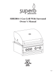
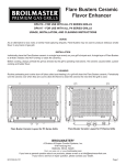
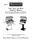
SIDE BURNER OWNER’S MANUAL
MODEL DPSBSS
(NATURAL
FOR
USE WITH
OR
PROPANE)
BROILMASTER® PREMIUM GAS GRILLS
RETAIN OWNER’S MANUAL FOR FUTURE REFERENCE.
B100027-0-0202
DPSBSS
Page 1
THIS GAS APPLIANCE IS DESIGNED FOR OUTDOOR USE ONLY
IMPORTANT
THIS
MANUAL SHOULD BE READ THOROUGHLY BY THE PERSON INSTALLING THE SIDE BURNER AND ALL
PERSONS WHO WILL USE AND MAINTAIN THE SIDE BURNER.
IS LEFT IN THE POSSESSION OF THE USER.
THE INSTALLER SHOULD BE SURE THE MANUAL
THE USER SHOULD RETAIN THIS MANUAL FOR FUTURE REFERENCE
WHEN USING OR CLEANING THE SIDE BURNER AND TO PROPERLY IDENTIFY ANY REPAIR PARTS THAT MAY
BE REQUIRED.
WARNING
REFERENCE
THIS MANUAL FOR PROPER INSTALLATION AND MAINTENANCE INSTRUCTIONS.
IMPROPER
INSTALLATION, ADJUSTMENT, ALTERATION, SERVICE OR MAINTENANCE CAN CAUSE PERSONAL INJURY OR
PROPERTY DAMAGE.
FOR ASSISTANCE OR ADDITIONAL INFORMATION CONSULT A QUALIFIED INSTALLER,
SERVICE AGENCY OR THE GAS SUPPLIER.
CAUTION: FOR YOUR SAFETY
IF YOU SMELL GAS:
1.
2.
3.
4.
SHUT OFF GAS TO THE APPLIANCE.
EXTINGUISH ANY OPEN FLAME.
OPEN THE GRILL LID.
IF ODOR CONTINUES, IMMEDIATELY CALL YOUR GAS SUPPLIER OR
FIRE DEPARTMENT.
5. DO NOT TOUCH ELECTRICAL SWITCHES.
CAUTION: FOR YOUR SAFETY
1. DO NOT STORE OR USE GASOLINE OR OTHER FLAMMABLE VAPORS AND LIQUIDS IN THE VICINITY OF
THIS OR ANY OTHER APPLIANCE.
2. AN LP CYLINDER NOT CONNECTED FOR USE SHALL NOT BE STORED IN THE VICINITY OF THIS OR ANY
OTHER APPLIANCE.
CAUTION:
PARTS MAY HAVE SHARP EDGES. WEAR LEATHER WORK GLOVES AND HANDLE PARTS CAREFULLY DURING
THE UNPACKING, ASSEMBLY AND THE INSTALLATION.
WARNING
BROILMASTER SIDE BURNERS EQUIPPED FOR PROPANE GAS MUST ONLY USE PROPANE CYLINDERS
EQUIPPED WITH AN OVERFILL PROTECTION DEVICE (OPD). USE ONLY A REPUTABLE PROPANE DEALER
WHEN EXCHANGING OR FILLING CYLINDERS. AN OVERFILLED OR IMPROPERLY FILLED PROPANE CYLINDER
CAN BE DANGEROUS.
Page 2
DPSBSS
TABLE
OF
CONTENTS
C ONGRATULATIONS !
You have chosen the finest side burner for your outdoor cooking pleasure. Please take time
to read this entire manual before assembling your premium Broilmaster® gas side burner.
C22
Parts Diagram ............................................................................................................................... 4
Parts List ...................................................................................................................................... 5
Side Burner Assembly ...............................................................................................................6-7
Propane Gas Connection ........................................................................................................ 8-10
Natural Gas Connection ........................................................................................................ 11-12
Operation and Maintenance ....................................................................................................... 13
Gas Leaks ............................................................................................................................... 13
Operation ................................................................................................................................... 13
Notes ........................................................................................................................................ 14-15
Your Broilmaster® Side Burner is identified by model number, serial number, and gas
type. This information is provided on a product identification label located on the Side
Burner. The grill’s model number, serial number, and gas type must also be provided
when contacting your Broilmaster® dealer. For your convenience, complete this section
for future reference when contacting your dealer.
Grill Information
Model No.
Dealer
Serial No.
Dealer Phone No.
Gas Type: Propane
Natural
Date of Purchase
Side Burner Information
Model No.
DPSBSS
Dealer
Serial No.
Gas Type: Propane
DPSBSS
Dealer Phone No.
Natural
Date of Purchase
Page 3
PARTS DIAGRAM
SIDE BURNER EXPLODED VIEW
Page 4
DPSBSS
4
PARTS LIST
All repair part orders should be placed through your local Broilmaster® dealer. To locate a dealer in your
area, contact Broilmaster Customer Service at 800-851-3153 • WWW.broilmaster.com. To ensure prompt and
accurate service, please provide the following information when placing a repair part order: Model number
of your Side Burner, Part Name, Part Number, and Quantity of parts needed.
Key
No.
1
2
3
4
5
6
7
8
9
10
11
12
13
14
15
16
17
18
18
19
20
21
22
23
24
25
26
27
28
DPSBSS
Part Name
Bumper
10 X 3/8 Screw
Cooking Grid
Control Panel Label
Ignitor Ground Wire
Valve
Valve Knob
Electronic Ignitor
10-24 X 3/8 Screw
Tie-Down Bracket
Ignitor Ground Lug
9/32 Flat Washer
10-24 Wing Nut
Handle
Side Burner Lid
Side Burner Body
1/4-20 X 3/4 Phillips Truss Screw
Orifice (LP) No. 89
Orifice (NAT) No. 173
Burner Complete (Includes 18, 25, 26, 27)
Tee Fitting
Mounting Plate
Side Burner S/S Flex Line 10"
Side Burner S/S Flex Line 34"
Manifold Tube
Burner Cap
Ring (LP Only) (Not SHown)
Burner (Not Shown)
Handle Shelf Bracket
Qty.
2
2
1
1
2
1
1
1
2
1
1
1
1
1
1
1
1
1
1
1
1
1
1
1
1
1
1
1
1
Part Number
B100103
B053779
B070100
B072698
B072684
B070483
B070084
B072218
B100130
B070081
B069747
B100136
B100125
B059229
B076984
B076985
B072217
B100226
B073270
B100278
B070323
B070142
B070487
B070289
B070108
B070584
B073953
B100227
B073100
Page 5
S IDE BURNER ASSEMBLY
Instructions
®
All Broilmaster side burners require some assembly
and installation. Certain instructions may not apply
to your model of side burner. This side burner requires
the same gas type (natural or liquid propane) as your
Broilmaster® gas grill. Your side burner is factory
equipped for LP gas. Natural gas conversion
instructions are located in the Natural Gas section of
this manual.
Igniter Assembly
Attach one end of the igniter wire (5) to the open terminal
on the back of the electronic igniter.
Install AA Alkaline battery
FIGURE 2
Igniter Wire (5)
Electronic
Igniter (8)
Please locate and follow in listed order only the
instructions for assembly and installation of the
correct gas type. Skip any sections that do not pertain
to the side burner model you have purchased.
PreAssembly
Every assembly and installation instruction includes
detailed illustrations to aid in assembly.
Compare the materials found in the shipping container
to the parts list provided. Every effort has been made
to ensure the correct parts have been provided. In
the event of an error, please contact your local
Broilmaster® dealer regarding the replacement of
missing parts.
The following items are needed for the assembly of
your side burner:
Phillips screwdriver
Two adjustable wrenches
Soapy water solution (to test for leaks)
+
-
Burner (21)
AA Alkaline
Battery
Positioning Side Burner
Slide side burner right side up onto right grill pull handle.
Attach with one 1/4-20 x 3/4 screw (17). FIGURE 3.
FIGURE 3
Grill Pull Handle
Attach the pull handle to the right side of the grill as
illustrated in Figure 1. Place two bolts into holes in
pull handle and through holes on right sides of grill
bottom. Fasten each bolt with a washer, lock washer
and nut.
17
FIGURE 1
Page 6
DPSBSS
S IDE B URNER ASSEMBLY
Mounting Side Burner
Lid Handle
Insert the notched end of the tie-down bracket
(10) into the slot on the mounting plate (21). Push
the other end of the tie-down bracket onto the
screw. Fasten with an igniter ground lug (11), a
washer (12) and wing nut (13). FIGURE 4.
Attach the lid handle (14) to the side burner lid
(15) using two phillips head self-tapping screws
(2). FIGURE 6.
Handle (14)
FIGURE 6
FIGURE 4
13
Lid (15)
12
11
Tie-Down
Bracket (10)
Mounting
Plate (23)
Cooking Grid
Position the cooking grid (3) over the burner as
shown by FIGURE 7.
FIGURE 7
Attach the igniter ground wire (5) onto the igniter
ground lug (11) terminal. FIGURE 5.
Cooking Grid (3)
FIGURE 5
Igniter
Ground Wire (5)
11
DPSBSS
Page 7
P ROPANE G AS C ONNECTION
Side Burner Location
Gas Type
Your grill and side burner have been designed for
outdoor use ONLY.
Your Broilmaster® side burner is factory equipped
for LP gas. Natural gas conversion instructions
are located in the Natural Gas section of this
manual. Never use liquid propane gas with a grill
designed for natural gas, or natural gas with a grill
designed for liquid propane gas. The type gas
required for your grill can be determined from its
product identification label. Questions regarding
different types of gases should be directed to your
gas supplier.
This side burner mounts on the right side of a
Broilmaster® gas grill and cannot be used with
another grill or for any other purpose.
You should never install or operate your grill and
side burner in any building, garage, or other
enclosed area.
For your safety, the grill and side burner
should not be installed or operated under any
combustible materials, such as carports,
covered porches, awnings, or overhangs.
Never install or use your grill and side burner
in or on any recreational vehicle or boat.
CAUTION: THE INSTALLATION AND OPERATION OF
THIS GRILL AND SIDE BURNER AT CLEARANCES LESS
THAN SPECIFIED BELOW MAY CAUSE A FIRE, PROPERTY
DAMAGE, OR PERSONAL INJURY.
A minimum clearance of sixteen (16") inches is
required from all sides of the side burner to any
combustible material. Refer to the grill’s Owner’s
Manual for specific grill clearances.
Examples of combustible materials are patio
furniture, fences, or the wall of your home.
The area surrounding the grill and side burner
should be clear to ensure proper ventilation. Do
not obstruct the flow of combustion and ventilation
air in any way. The ventilation openings on the
propane cylinder enclosure must also remain free
and clear of debris.
Portable grills with side burners should be level
and positioned away from direct wind prior to each
use.
WARNING: DO
NOT INSTALL OR OPERATE THIS
GRILL AND SIDE BURNER WHERE GASOLINE OR OTHER
FLAMMABLE MATERIALS ARE USED OR STORED. FAILURE
TO COMPLY WITH THIS WARNING COULD RESULT IN
EXPLOSION OR FIRE CAUSING PROPERTY DAMAGE OR
PERSONAL INJURY.
Page 8
Cylinder Requirements
Your Broilmaster® Premium Gas Grill requires a
standard twenty (20) pound propane gas cylinder.
The propane gas cylinder used must be:
1. constructed and marked in accordance with the
specifications for LP gas cylinder of the U.S.
Department of Transportation (D.O.T.) or the
National Standard of Canada, CAN/CSA-B339,
Cylinders, Spheres, and Tubes for Transportation
of Dangerous Goods; and Commission as
applicable.
2. provided with a listed overfilling protection device
(OPD).
3. provided with a listed safety device having direct
access with the vapor space of the cylinder and
the cylinder supply system must be arranged
for vapor removal.
4. provided with a shutoff valve terminating in a
valve outlet as specified in the Standard for
Compressed Gas Cylinder Outlet and Inlet
Connections, ANSICGA-V-1.
5. provided with a plug to effectively seal off the
cylinder outlet when the cylinder is being stored
or transported.
6. provided with a collar to protect the cylinder
valve.
CAUTION: DO NOT USE A PROPANE GAS CYLINDER
WHICH HAS A CAPACITY GREATER THAN TWENTY (20)
POUNDS WITH THIS GRILL AND SIDE BURNER.
DPSBSS
P ROPANE G AS C ONNECTION
Propane Cylinder Safety
Connection Requirements
Liquid propane gas has a long history of safe use
when the safety precautions provided in this
manual are followed.
CAUTION: NEVER USE LIQUID PROPANE GAS IN A GRILL
DESIGNED FOR NATURAL GAS, OR NATURAL GAS IN A
GRILL DESIGNED FOR LIQUID PROPANE GAS. QUESTIONS
FAILURE
REGARDING DIFFERENT TYPES OF GASES SHOULD BE
DIRECTED TO YOUR LOCAL GAS COMPANY.
TO FOLLOW THESE SAFETY PRECAUTIONS
COULD RESULT IN A FIRE OR EXPLOSION CAUSING
PROPERTY DAMAGE OR PERSONAL INJURY.
Propane gas cylinders should always be handled,
stored, and transported with extreme caution in a
secured upright position.
Never attempt to use or repair a propane gas
cylinder that has been damaged. Never attempt
to use or repair a cylinder with a faulty or damaged
valve outlet. A cylinder that has been dropped,
dented, or otherwise damaged must be replaced.
A propane gas cylinder should never be
transported in the passenger area of a vehicle.
Keep cylinders out of direct sunlight and never
apply any other source of direct heat to them.
When refilling your cylinder, always insist on a
reputable, qualified gas dealer. Your propane gas
cylinder is filled by weight, and should never
exceed eighty (80%) percent of its weight limit. If
the cylinder is not completely empty, the gas
dealer must make necessary adjustments to
ensure it is not overfilled. Never use an overfilled
Propane gas cylinder.
Cylinder Storage
Installation must conform to local codes or, in the
absence of local codes, with the National Fuel Gas
Code, ANSI Z223.1. In Canada, installation shall
be in accordance with CAN/CGA-B149.2 Propane
Installation Code, or CAN/CGA-B149.1 Natural
Gas Installation Code, and local codes where
applicable. Consult your local gas company or
Propane gas dealer for code regulations and
recommended procedures.
WARNING: BROILMASTER® GAS GRILLS AND SIDE
BURNERS REQUIRE LIQUID PROPANE CYLINDERS
EQUIPPED WITH AN OVERFILL PROTECTION DEVICE
(OPD). AN OVERFILLED OR IMPROPERLY FILLED
PROPANE CYLINDER CAN BE DANGEROUS.
Always use the pressure regulator and hose
assembly supplied with your propane gas grill.
Note: Not all valve and cylinder combinations are
compatible. Check warning tag on valve and
cylinder as well as external fitting threads.
All Broilmaster® pressure regulators and hose
assemblies require propane cylinders with a Type
1 connection device as illustrated by Figure 8.
FIGURE 8
Your grill must be stored outdoors in a well
ventilated area if the cylinder is attached to it.
Disconnected cylinders must have a threaded
valve plug tightly installed and must not be stored
in any building, garage, or other area.
Flammable materials (gasoline, grill covers, etc.)
must not be stored in the cylinder enclosure.
Always store propane cylinders in a secured
upright position, out of the reach of children.
DPSBSS
Page 9
P ROPANE G AS C ONNECTION
Pressure Regulator and
Hose Assembly
The pressure regulator has an outlet pressure of not
more than eleven (11") inches water column. It must
be connected to the propane gas cylinder’s female
valve outlet before the grill and side burner can be
operated.
CAUTION: OPERATION OF A PROPANE GAS GRILL AND
SIDE BURNER WITHOUT THE PRESSURE REGULATOR AND
HOSE ASSEMBLY WILL CAUSE GAS LEAKS WHICH COULD
LEAD TO FIRE OR EXPLOSION, RESULTING IN PROPERTY
DAMAGE OR PERSONAL INJURY.
The pressure regulator’s fitting must remain clean
and free of nicks and scratches. A dirty, nicked or
scratched fitting can cause a gas leak, resulting in
an explosion or fire. Use only genuine Broilmaster®
replacement parts unless otherwise specified by the
manufacturer.
FIGURE 10
10" S/S flex line (22)
Grill Gas Valve
"Tee" (20)
Connecting to Propane Gas
Attach one end of the 34" S/S flex line (23) to the
end of the side burner valve (6). Attach the remaining
end of the hose to the "tee" (20) and use two
wrenches to tighten the S/S flex line connections.
One wrench should be used to turn the S/S flex line
connector while the "tee" or valve is held with the
second wrench. FIGURE 11.
"Tee" (20) 34" S/S flex line (23) 6
FIGURE 11
Installing "Tee" Connector
If your grill is equipped with a factory installed gas
"tee" behind the grill’s control panel, please skip to
the next section.
For old Broilmaster grill, this alternate tee fitting kit
must be ordered.
Turn OFF the gas valve at the propane cylinder.
Disconnect the regulator and hose assembly from
the cylinder. Disconnect hose from the gas valve
located under the grill’s control panel. FIGURE 9.
FIGURE 9
Grill Gas Valve
Hose Assembly
Attach the regulator and hose assembly to the brass
tee" (20). Reconnect the assembly to the cylinder.
Use two adjustable wrenches to hold and tighten
the joint between the hose and "tee". FIGURE 12.
Installing “Tee” Connector
20
FIGURE 12
(Continued)
Attach one end of the 10" S/S flex line (22) to the
end of the grill’s gas valve. Attach the other end of
the S/S flex line to the brass "tee" (20). FIGURE 10.
NOTE: GRILLS MANUFACTURED PRIOR TO 1999 MAY REQUIRE
"TEE" CONNECTOR.
THE ALTERNATE
Page 10
DPSBSS
N ATURAL G AS C ONNECTION
Side Burner Location
Gas Type
Your grill and side burner have been designed for
outdoor use ONLY.
Your Broilmaster® side burner is factory equipped
for LP gas and must be converted for use with
Natural gas grills. Never use liquid propane gas
with a grill designed for natural gas, or natural gas
with a grill designed for liquid propane gas. The
type gas required for your grill can be determined
from its product identification label. Questions
regarding different types of gases should be
directed to your gas company.
This side burner mounts on the right side of a
Broilmaster® gas grill and cannot be used with
another grill or for any other purpose.
You should never install or operate your grill and
side burner in any building, garage, or other
enclosed area.
For your safety, the grill and side burner should
not be installed or operated under any combustible
materials, such as carports, covered porches,
awnings, or overhangs.
Never install or use your grill and side burner in
or on any recreational vehicle or boat.
CAUTION: THE INSTALLATION AND OPERATION OF
THIS GRILL AND SIDE BURNER AT CLEARANCES LESS
THAN SPECIFIED BELOW MAY CAUSE A FIRE, PROPERTY
DAMAGE, OR PERSONAL INJURY.
A minimum clearance of sixteen (16") inches is
required from all sides of the side burner to any
combustible material. Refer to the grill’s Owner’s
Manual for specific grill clearances.
CAUTION: NEVER USE LIQUID PROPANE GAS IN A GRILL
DESIGNED FOR NATURAL GAS, OR NATURAL GAS IN A
GRILL DESIGNED FOR LIQUID PROPANE GAS. QUESTIONS
REGARDING DIFFERENT TYPES OF GASES SHOULD BE
DIRECTED TO YOUR LOCAL GAS COMPANY.
BURNER
TOP
89
BRASS
ORIFICE
89
DENOTES (LP)
BRASS ORIFICE
SHUTTER
SCREW
SHUTTER
RING
173
SIDE
BURNER
173
DENOTES
(NAT) BRASS
ORIFICE
Examples of combustible materials are patio
furniture, fences, or the wall of your home.
1. Remove shutter screw. Important: Do not
discard this screw; it will be reinstalled.
The area surrounding the grill and side burner
should be clear to ensure proper ventilation. Do
not obstruct the flow of combustion and ventilation
air in any way. The ventilation openings on the
propane cylinder enclosure must also remain free
and clear of debris.
2. Remove shutter ring. The shutter ring is not
used for Natural gas, but retain for future use
if LP conversion is desired.
Portable grills with side burners should be level
and positioned away from direct wind prior to each
use.
WARNING: DO
NOT INSTALL OR OPERATE THIS
GRILL AND SIDE BURNER WHERE GASOLINE OR OTHER
FLAMMABLE MATERIALS ARE USED OR STORED. FAILURE
TO COMPLY WITH THIS WARNING COULD RESULT IN
EXPLOSION OR FIRE CAUSING PROPERTY DAMAGE OR
PERSONAL INJURY.
DPSBSS
3. Use a 7 mm nut driver or socket wrench to
remove the LP orifice and replace it with the
Natural gas orifice supplied.
4. Replace the shutter screw.
5. Turn set screw in center of valve stem 1/2 turn
counterclockwise.
6. Apply soapy solution to test for leaks around
the set screw. If a leak is found, turn screw
clockwise until bubbles cease.
IMPORTANT : PLACE
CONVERSION LABEL INSIDE LID
ADJACENT TO SERIAL NUMBER LABEL.
Page 11
N ATURAL G AS C ONNECTION
Connection Requirements
Installation must conform to local codes or, in the
absence of local codes, with the National Fuel Gas
Code, ANSI Z223.1. In Canada, installation shall
be in accordance with CAN/CGA-B149.2 Propane
Installation Code, or CAN/CGA-B149.1 Natural
Gas Installation Code, and local codes where
applicable. Contact your local gas company for
code regulations, recommended procedures, and
the installation of your grill’s gas supply line.
Attach one end of the 10" S/S flex line (22) to the
end of the grill’s gas valve.
Attach the other end of the S/S flex line to the
brass “tee” (20). FIGURE 14.
FIGURE 14
7" S/S flex line (22)
“Tee” (20)
Broilmaster® gas grills and side burners are not
equipped with pressure regulators. Your gas grill
operates at a manifold pressure of seven (7")
inches water column.
Connect cart mounted natural gas grills to a preinstalled gas supply line using the twelve (12') foot
flexible hose and quick disconnect kit supplied or
specified by the manufacturer.
CAUTION: THE
GRILL AND ITS INDIVIDUAL SHUTOFF
VALVE MUST BE DISCONNECTED FROM THE GAS SUPPLY
PIPING SYSTEM DURING ANY SYSTEM PRESSURE TESTING
Grill Gas Valve
Attach one end of the 34" S/S flex line (23) to the
end of the side burner valve (6).
Attach the remaining end of the S/S flex line to
the end of the “tee” (20) connector. FIGURE 15.
AT TEST PRESSURES IN EXCESS OF 1/2 PSIG.
CAUTION: THE GRILL MUST BE ISOLATED FROM THE
20
34" S/S flex line (23)
6
GAS SUPPLY PIPING SYSTEM BY CLOSING ITS INDIVIDUAL
MANUAL SHUTOFF VALVE DURING ANY PRESSURE
TESTING OF THE GAS SUPPLY PIPING SYSTEM AT TEST
PRESSURES EQUAL TO OR LESS THAN 1/2 PSIG.
FIGURE 15
Connection Instructions
The grill’s natural gas supply line valve installed
by your gas company must be turned to OFF.
IMPORTANT:
THE GAS SUPPLY LINE MUST HAVE A
SHUTOFF VALVE INSIDE THE WALL. CONTACT YOUR
LOCAL GAS COMPANY FOR DIRECTIONS.
Disconnect the copper gas supply line from the
gas valve located under the grill’s control panel.
FIGURE 13.
FIGURE 13
Gas Supply Line
Attach the copper gas supply line to the brass
“tee” (20). Use two adjustable wrenches to tighten
the joint. FIGURE 16.
FIGURE 16
“Tee” (20)
Gas Supply Line
Grill Gas Valve
Page 12
DPSBSS
O PERATION
AND
M AINTENANCE
Checking for Gas Leaks
Operating Instructions
Check for gas leaks each time you connect your
Broilmaster® gas grill and side burner to a propane
gas cylinder, when a connected cylinder has not
been used recently, or when the grill and side
burner are initially used.
CAUTION: IF A BURNER FAILS TO LIGHT AFTER 5
SECONDS, TURN THE BURNER OFF FOR 5 MINUTES, TO
ALLOW THE GAS TO CLEAR, THEN TRY AGAIN.
CAUTION: DO NOT USE AN OPEN FLAME TO CHECK
FOR LEAKS. CHECKING FOR LEAKS WITH AN OPEN
FLAME MAY LEAD TO A FIRE OR EXPLOSION, RESULTING
IN PROPERTY DAMAGE OR PERSONAL INJURY.
WARNING: NEVER OPERATE THE SIDE BURNER WITH
THE LID CLOSED.
Care and Cleaning
To check for gas leaks:
CAUTION: TO PREVENT INJURY DO NOT CLEAN SIDE
BURNER WHILE HOT.
1. Using dish washing detergent and water, make
a soapy solution.
For baked on residue use a brass (NOT STEEL)
brush on the cooking grid.
2. Turn OFF the knob on both the grill and side
burner’s control panel.
Clean the exterior regularly with a solution of mild
detergent and hot water.
3. Turn ON the gas at the supply. A hissing sound
indicates a leak. Turn OFF the gas and repair
all leaks.
4. If no hissing occurs, apply the soapy solution
to all gas connections.
5. Look for bubbles. Bubbles indicate a leak.
6. If there are bubbles, turn OFF the gas and
repair all leaks.
7. Turn the gas ON and repeat the above
procedure until all leaks are repaired.
Operating Instructions
Using the Igniter
1. Open the side burner lid.
2. Push and turn the burner control knob
counterclockwise to MAX.
3. Push and hold igniter button until burner lights.
(Approximately 5 seconds).
Using Matches
1. Open the side burner lid.
2. Light and place a long wooden match next to
Stainless steel surfaces can be easily cleaned
with a stainless steel cleaner found at your
Low Flame Adjustment
The low flame setting is set at the factory. To adjust
the flame height at the lowest setting:
A. Light the side burner
B. Turn the valve knob to MIN.
C. Remove the knob and locate the screw in the
center of the valve stem.
D. Use a small screwdriver to adjust the flame:
Clockwise - Lower Flame
Counterclockwise - Higher Flame
Do not unseat the adjustment screw. If the screw
is unseated a gas leak will occur at the valve stem.
NOTE: IF THE FLAME IS ADJUSTED TOO LOW, A STRONG
WIND COULD BLOW IT OUT. THE FLAME MAXIMUM HEIGHT
(A) SHOULD BE APPROXIMATELY 1/2 INCH AT THE MINIMUM
SETTING. FIGURE 17.
FIGURE 17
BURNER
the burner ports under the cooking grid.
3. Push and turn the burner control knob
1/2
counterclockwise to MAX.
DPSBSS
Page 13
NOTES
Page 14
DPSBSS
NOTES
DPSBSS
Page 15
BROILMASTER®
A Division of Empire Comfort Systems, Inc.
918 Freeburg Ave.
Belleville, Illinois 62220
Phone: 800-255-0403
RETAIN OWNER’S MANUAL FOR FUTURE REFERENCE.
FORM B100027-2-0202
Page 16
DPSBSS