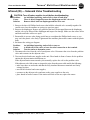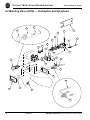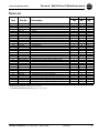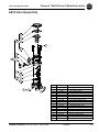
1
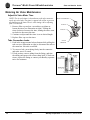
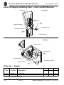
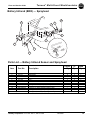
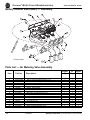
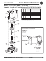
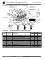
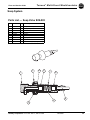
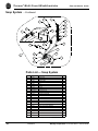
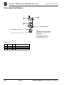
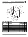
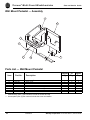
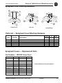
Multi-Fount Washfountains
Terreon® Models
Parts & Service Guide
215-1447 Rev. F; EN 07-005A
©2007 Bradley Corporation
Page 1 of 34 1/30/2008
P.O. Box 309, Menomonee Falls, WI 53052-0309
TEL. 1-800-Bradley FAX 262-251-5817
http://www.bradleycorp.com
Terreon ® Multi-Fount Washfountains
Parts and Service Guide
Table of Contents
Washfountain Identification
Page #
Identification Chart and Model Numbers . . . . . . . . . . . . . . . . . . . . . . . . . . . . . . . . . . . . . . . . . . . . . . .3
Terreon® Multi-Fount Washfountains
Infrared (IR) — Sprayhead (24V plug-in transformer) . . . . . . . . . . . . . . . . . . . . . . . . . . . . . . . . . . . . .4
Infrared (IR) — Valves (24V plug-in transformer) . . . . . . . . . . . . . . . . . . . . . . . . . . . . . . . . . . . . . .5-6
Infrared (IR)— Solenoid Valve Troubleshooting . . . . . . . . . . . . . . . . . . . . . . . . . . . . . . . . . . . . . . . . .7
Air Metering Valve (AST4) — Pushbutton and Sprayhead . . . . . . . . . . . . . . . . . . . . . . . . . . . . . . .8-9
Air Metering Valve (AST4) — Assembly . . . . . . . . . . . . . . . . . . . . . . . . . . . . . . . . . . . . . . . . . . . . . .10
Air Metering Valve (AST4) — Repair Kits . . . . . . . . . . . . . . . . . . . . . . . . . . . . . . . . . . . . . . . . . . . .11
Metering Air Valve Maintenance and Troubleshooting . . . . . . . . . . . . . . . . . . . . . . . . . . . . . . . . .12-13
AST4 & IR Supply and Mixing Valve — Floor and Wall Mounted . . . . . . . . . . . . . . . . . . . . . . . . .14
Battery Infrared (BIR3) — Sprayhead . . . . . . . . . . . . . . . . . . . . . . . . . . . . . . . . . . . . . . . . . . . . . . . .15
Battery Infrared (BIR3) — Valves . . . . . . . . . . . . . . . . . . . . . . . . . . . . . . . . . . . . . . . . . . . . . . . . .16-17
Troubleshooting (BIR3) Components . . . . . . . . . . . . . . . . . . . . . . . . . . . . . . . . . . . . . . . . . . . . . . . . .18
TouchTime® (TT) — Sprayhead (24V plug-in transformer) . . . . . . . . . . . . . . . . . . . . . . . . . . . . .19-21
TouchTime® (TT) Solenoid Valve Troubleshooting . . . . . . . . . . . . . . . . . . . . . . . . . . . . . . . . . . . . . .22
Mixing Valve — Vernatherm® — Thermostatic S01-520 Valve . . . . . . . . . . . . . . . . . . . . . . . . . .23-24
Cleaning the Strainer . . . . . . . . . . . . . . . . . . . . . . . . . . . . . . . . . . . . . . . . . . . . . . . . . . . . . . . . . . .23-24
Soap System . . . . . . . . . . . . . . . . . . . . . . . . . . . . . . . . . . . . . . . . . . . . . . . . . . . . . . . . . . . . . . . . . .25-27
Drain Spud and Strainer . . . . . . . . . . . . . . . . . . . . . . . . . . . . . . . . . . . . . . . . . . . . . . . . . . . . . . . . . . .28
Floor Pedestal — Assembly . . . . . . . . . . . . . . . . . . . . . . . . . . . . . . . . . . . . . . . . . . . . . . . . . . . . . . . .29
Wall Mount Pedestal — Assembly . . . . . . . . . . . . . . . . . . . . . . . . . . . . . . . . . . . . . . . . . . . . . . . . . . .30
Sprayhead Cover Attaching Hardware . . . . . . . . . . . . . . . . . . . . . . . . . . . . . . . . . . . . . . . . . . . . . . . .31
Sprayhead Covers — Replacement Parts . . . . . . . . . . . . . . . . . . . . . . . . . . . . . . . . . . . . . . . . . . . .31-32
Pedestal Panels . . . . . . . . . . . . . . . . . . . . . . . . . . . . . . . . . . . . . . . . . . . . . . . . . . . . . . . . . . . . . . . . . . .32
Terreon Care and Maintenance . . . . . . . . . . . . . . . . . . . . . . . . . . . . . . . . . . . . . . . . . . . . . . . . . . . . . .33
Bowl Assembly . . . . . . . . . . . . . . . . . . . . . . . . . . . . . . . . . . . . . . . . . . . . . . . . . . . . . . . . . . . . . . . . . .34
Part numbers are subject to change without formal notice.
2
1/30/2008
Bradley Corporation • 215-1447 Rev. F; EN 07-005A
Terreon ® Multi-Fount Washfountains
Parts and Service Guide
Terreon® Multi-Fount Washfountains
•
•
•
•
Unique, Repairable, Solid Surface Material
Highly Vandal Resistant
Saves Water, Energy, and Space
Available with Air Metering, Infrared or Battery
Operated Infrared and TouchTime® Control
Models Available:
MF2922
MF2933
MF2939
MF2944
MF2949
Terreon
Terreon
Terreon
Terreon
Terreon
Corner-Fount
Tri-Fount
Tri-Fount Wall Hung
Quadra-Fount
Quadra-Fount Wall Hung
MF2922
Air Valve
Shown (AST)
MF2933
Air Valve
Shown (AST)
MF2939
Air Valve
Shown (AST)
Bradley Corporation • 215-1447 Rev. F; EN 07-005A
MF2944
Infrared Shown (IR)
MF2949
Infrared Shown (IR)
1/30/2008
3
Terreon ® Multi-Fount Washfountains
Parts and Service Guide
Infrared (IR) — Sprayhead (24V Plug-in Transformer)
1
10
6
4
7
8
5
3
1
2
9
Parts List — Infrared Sensor and Sprayhead Assembly
*
4
Item
Part No.
1
*
2
3
4
5
6
7
8
9
10
10
10
10
269-1608
P10-569
269-1190
115-131
176-119
140-748
161-026
142-002BS
269-871
269-628
R68-600011-R
R68-600011-G
R68-600011-B
R68-600011-Y
Corner
Qty
Description
Sensor - Adaptive
Hook and Loop Fastener Strip (sensor mounting)
Window
Sprayhead
Threaded Rod
Backplate
Nut
Lockwasher
Fitting Straight (front sprayhead)
Fitting Swivel 90° (side sprayheads)
Tubing 1/4", Red (Specify Length in feet)
Tubing 1/4", Green (Specify Length in feet)
Tubing 1/4", Black (Specify Length in feet)
Tubing 1/4", Yellow (Specify Length in feet)
2
2
4
2
4
2
4
4
—
2
—
—
—
—
Tri
Qty
3
3
6
3
6
3
6
6
1
2
—
—
—
—
Quad
Qty
4
4
8
4
8
4
8
8
2
2
—
—
—
—
Not Illustrated.
1/30/2008
Bradley Corporation • 215-1447 Rev. F; EN 07-005A
Terreon ® Multi-Fount Washfountains
Parts and Service Guide
Infrared (IR) — Valves (24V Plug-in Transformer)
13
7
9
10
Black Supply Tube
(From Sprayhead)
Green Supply Tube
(From Sprayhead)
15
Red Supply Tube
(From Sprayhead)
8
12
11
Red Spade Terminal
Green Spade Terminal
1
4
2
Black Spade Terminal
5
3
6
White Jumper Terminals
Tri-Fount Shown
14
Parts List — Solenoid Assembly and Valve Parts
Item
1
2
3
4
5
6
7
8
9
10
11
12
13
14
15
Part No.
Description
S45-2084
S45-2085
S45-2090
S45-2091
S45-2162
S45-2163
S01-520
140-928
P18-054
S07-068A
S07-068
110-231
160-447
S39-685
S83-152
IR TMA Dual Valve Assembly (includes 7-13)
IR TL Dual Valve Assembly (includes 8-14)
IR TMA Tri Valve Assembly (includes 7-13)
IR TL Tri Valve Assembly (includes 8-14)
IR TMA Quad Valve Assembly (includes 7-13)
IR TL Quad Valve Assembly (includes 8-14)
Vernatherm Valve, 4 GP
Bracket, Ganged Valve
Screw 10-24 x 3/8 PN
Solenoid Valve, 24 VAC, through
Solenoid Valve, 24 VAC, closed
Compression Nut, 1/4"
Screw 8-16 x 5/8 PN
Adapter, Valve Inlet
Transformer
Bradley Corporation • 215-1447 Rev. F; EN 07-005A
Corner
Qty
1
1
—
—
—
—
1
1
2
1
1
2
2
1
1
1/30/2008
Tri
Qty
—
—
1
1
—
—
1
1
2
2
1
3
3
1
1
Quad
Qty
—
—
—
—
1
1
1
1
2
3
1
4
4
1
1
5
Terreon ® Multi-Fount Washfountains
Parts and Service Guide
Infrared Valve (IR) — Assembly —
Solenoid Valve S07-068 (closed body) and S07-068A (thru body)
8
7
8
REF.
1
1
2
3
4
5
6
7
8
9
10
QTY.
1
1
1
1
1
1
1
1
3
1
1
PART NO.
118-307
118-307A
269-983
269-577
269-578
269-1729
269-1730
269-579
160-447
125-165
125-160
DESCRIPTION
VALVE BODY, 1/4" CLOSED
VALVE BODY, 1/4" THRU
DIAPHRAGM
ARMATURE
SPRING
ARMATURE HOUSING
CLAMP, ARMATURE HOUSING
COIL, SOLENOID VALVE
SCREW, #8 X 5/8
O-RING, #2-013
FLOW RESTRICTOR, .5 GPM
11
1
S65-113
REPAIR KIT
6
5
4
11
3
2
10
1
9
6
1/30/2008
Bradley Corporation • 215-1447 Rev. F; EN 07-005A
Parts and Service Guide
Terreon ® Multi-Fount Washfountains
Infrared (IR) — Solenoid Valve Troubleshooting
CAUTION:
Problem:
Cause:
Solution:
Turn off water supplies to unit before troubleshooting.
An individual operating station fails to shut off and drips.
There is debris trapped between the diaphragm and the valve seat.
Remove debris between diaphragm and the valve seat.
1. Remove the three #8 Phillips-head screws that hold the solenoid valve assembly together. Be
careful not to lose the armature or spring (see previous page).
2. Remove the diaphragm. Remove any particles that have been trapped between the diaphragm
and the valve seat. Rinse off the diaphragm and inspect for damage. Make sure the center orifice
and both small side orifices are open.
3. Reassemble in reverse order, being careful not to overtighten the Phillips-head screws or you
may crack the plastic valve body. Tighten until the armature plate makes contact with the plastic
body.
4. Reconnect the wiring per diagram.
Problem:
An individual operating station fails to turn on.
Cause:
A failed coil for the valve or loose electrical connection to the terminal.
Solution:
Test the station to determine cause.
1. Disconnect the wires from the coil of an adjacent valve. Disconnect the wires from the problem
valve and reconnect to the adjacent valve.
2. Turn on electrical and water supplies to the unit. Place hands in front of sensor for the problem
station; the adjacent station should turn on.
If the adjacent station turns on and cycles normally, replace the coil on the problem valve.
If the adjacent valve fails to turn on, inspect the wires from the sensor cable and do the following:
• make sure there are no breaks and that the fully insulated disconnect terminals are firmly
crimped in place;
• turn off the electrical and water supplies;
• reconnect to the adjacent valve and turn on the water supplies to the unit;
• place hands in front of sensor. If the station still fails to turn on, replace the sensor.
Bradley Corporation • 215-1447 Rev. F; EN 07-005A
1/30/2008
7
Terreon ® Multi-Fount Washfountains
Parts and Service Guide
Air Metering Valve (AST4) — Pushbutton and Sprayhead
4
3
2
27
16
11 *
10 *
9
17
*
14 *
7
15
† 14
6
13
12
*
*
22
23
1
26
5
24
21
26
19
18
20
25
8
1/30/2008
Bradley Corporation • 215-1447 Rev. F; EN 07-005A
Parts and Service Guide
Terreon ® Multi-Fount Washfountains
Parts List
Item
Part No.
1
2
3
4
5
6
7
9*
10*
11*
12*
13*
14
15†
16
17
17
17
17
18
19
20
21
22
23
24
25
26
26
26
26
27
S08-340
128-090
179-104
147-034
182-110
140-743
110-115
S65-168
S65-168A
119-227A
125-099
135-065
118-279
198-010
169-890
269-1186
160-165
R68-600008-R
R68-600008-G
R68-600008-B
R68-600008-Y
115-131
176-119
269-1190
140-748
161-026
142-002BS
269-871
269-628
R68-600011-R
R68-600011-G
R68-600011-B
R68-600011-Y
130-023
Corner
Qty
Description
Pushbutton Assy. (Includes Items 2 thru 4)
Pushbutton only
Guide for pushbutton
Shoulder Screw for pushbutton
Spacer
Bracket
Nut
Actuator Assy. (Includes items 9 thru 14)
Actuator Assy. (Includes itmes 9 thru 15)
Piston
U-Cup
Spring
Actuator Body
Duckbill Check
Tube Connector 1/8" straight
Fitting Adj J
Screw
Tubing 1/8" OD, Red (specify length in feet)
Tubing 1/8" OD, Green (specify length in feet)
Tubing 1/8" OD, Black (specify length in feet)
Tubing 1/8" OD, Yellow (specify length in feet)
Sprayhead
Threaded Rod
Window Hole Plug
Backplate
Nut
Lockwasher
Fitting Straight (front sprayhead)
Fitting Swivel 90° (side sprayheads)
Tubing 1/4" ID, Red (specify Length in feet)
Tubing 1/4" ID, Green (specify Length in feet)
Tubing 1/4" ID, Black (specify Length in feet)
Tubing 1/4" ID, Yellow (specify Length in feet)
Spanner Wrench
2
2
2
2
2
2
2
2
—
2
2
2
2
2
2
—
4
—
—
—
—
2
4
4
2
4
4
—
2
—
—
—
—
1
Tri
Qty
3
3
3
3
3
3
3
1
2
3
3
3
3
3
3
2
6
—
—
—
—
3
6
6
3
6
6
1
2
—
—
—
—
1
Quad
Qty
4
4
4
4
4
4
4
2
2
4
4
4
4
4
4
2
8
—
—
—
—
4
8
8
4
8
8
2
2
—
—
—
—
1
* Repair Kit S65-168 (incl. parts 9, 10, 11, 12, 13)
*, † Repair Kit S65-168A (incl. parts 9, 10, 11, 12, 13, 15)
Bradley Corporation • 215-1447 Rev. F; EN 07-005A
1/30/2008
9
Terreon ® Multi-Fount Washfountains
Parts and Service Guide
Air Metering Valve (AST4) — Assembly
13
9
12
7
11
8
10
1
2
3
4
5
6
Tri-Fount Shown
14
Parts List — Air Metering Valve Assembly
10
Item
Part No.
1
2
3
4
5
6
7
8
9
10
11
12
13
14
S08-452TMA
S08-452TL
S08-453TMA
S08-453TL
S08-454TMA
S08-454TL
S01-520
140-928
P18-054
S07-078A
S07-078
110-231
160-447
S39-685
Corner
Qty
Description
TMA Dual Valve Assembly (includes 7-13 )
TL Dual Valve Assembly (includes 8-14 )
TMA Tri Valve Assembly (includes 7-13 )
TL Tri Valve Assembly (includes 8-14 )
TMA Quad Valve Assmbly (includes 7-13 )
TL Quad Valve Assmbly (includes 8-14 )
Vernatherm Valve, 4 GP
Bracket, Ganged Valve
Screw 10-24 x 3/8 PN
AST4 Valve, through
AST4 Valve, closed
Compression Nut, 1/4"
Screw 8-16 x 5/8 PN
Adapter, Valve Inlet
1/30/2008
1
1
—
—
—
—
1
1
2
1
1
2
2
1
Tri
Qty
—
—
1
1
—
—
1
1
2
2
1
3
3
1
Quad
Qty
—
—
—
—
1
1
1
1
2
3
1
4
4
1
Bradley Corporation • 215-1447 Rev. F; EN 07-005A
Terreon ® Multi-Fount Washfountains
Parts and Service Guide
AST4 Valve Repair Kits
14
13
16
12
15
11
10
9
18
8
7
6
17
5
4
2
3
1
Bradley Corporation • 215-1447 Rev. F; EN 07-005A
ITEM
PART NO.
DESCRIPTION
1
2
3
4
5
6
7
8
9
10
11
12
13
14
15
16
17
18
125-165
118-307A
118-307
269-983
269-577
269-578
118-309
107-538
S27-305
125-001BY
110-234
S39-591
107-535
110-233
160-449
S65-261
S65-262
S65-260
O-Ring
Valve Body-Manifolded
Valve Body-Closed
Diaphragm
Armature, Valve
Spring, Valve
Cover, AST4 Valve
Cover, AST4 Valve Timer
Timer, ASM, AST4 Valve
O-Ring
Compression Nut, 1/8”
Magnet/Diaphragm Assy
Cover, AST4 Valve
Clamp Nut, AST4 Valve
Screw 8-16 x 7/8”
Repair Kit-AST4Valve
Repair Kit-AST4 Valve-Upper
Repair Kit-AST4 Valve-Complete
1/30/2008
11
Terreon ® Multi-Fount Washfountains
Parts and Service Guide
Metering Air Valve Maintenance
Adjust Air Valve Meter Time
NOTE: The air valve timer is located next to the tube connector
on the air valve body. The timer is capped with a filter to prevent
dirt build-up on the timer. The air valve timing can be adjusting
from 5–60 seconds.
1. Remove filter cap and use a screwdriver to tighten or
loosen the timer (see illustration at right). Turning the
timer clockwise increases the time; turning the timer counterclockwise decreases the time.
2. Continue to adjust until the timer is set at desired length.
3. Replace filter cap over the timer.
Tube Connection Leaks
1. Push in the orange manual release button while pulling the
tube out (see illustration at right) to disconnect the tube at
the connector. No tools are needed.
2. To correct a leak, press tubing firmly into the connector
and make sure it is seated.
3. If leak persists, remove tubing from the fitting, and trim
the tubing end square with a razor-sharp knife. If leak continues, replace the fitting or contact your Bradley representative for assistance.
12
1/30/2008
WATER TUBE CONNECTOR
AIR VALVE
FILTER CAP
AIR TUBE
CONNECTOR
Bradley Corporation • 215-1447 Rev. F; EN 07-005A
Parts and Service Guide
Terreon ® Multi-Fount Washfountains
Metering Air Valve Troubleshooting
Problem: Valve will not shut off.
Cause: Timing mechanism is clogged.
Solution: Clean and inspect timing mechanism:
1. If compressed air is available, blow water and debris from timer cover of timing mechanism.
2. Turn adjusting screw out all the way. Clean and inspect screw and valve body.
3. Turn adjusting screw in to desired cycle time.
Problem: Valve will not turn on.
Cause: Water is not being supplied to unit.
Solution: Open all stops on mixing valve.
Cause: Water pressure is over 80 PSI.
Solution: Install a pressure reducing valve.
Cause: Failed diaphragm/magnet assembly.
Solution: Unscrew the valve clamp nut on valve. Remove valve cover. Gently press the the
diaphragm. The valve should activate. If not, replace the diaphragm/magnet assembly.
Problem: Timing can not be adjusted for more than 5 seconds.
Cause: There is an air leak
Solution: Check the valve assembly:
1. Check all tubing and fittings for proper assembly.
2. Tighten cap and nut on 1/8" tubing.
Problem: Pushbutton does not work properly.
Cause: Air volume may not be sufficient to operate valve.
Solution: Check for leaks and lubricate U-cup:
1. Check all fittings for air leaks.
2. Disassemble pushbutton and lubricate U-cup seal (see pushbutton assembly diagram on page 8).
Problem: Water is dripping from the streamformers.
Cause: Debris has accumulated on valve seat or orifices.
Solution: Clean and inspect valve seat.
1. Remove screws and disassemble metering valve.
2. Clean valve seat and inspect for deep gouges or scratches. Replace valve body if necessary.
3. Remove any debris clogging off-center hole in rubber diaphragm.
Bradley Corporation • 215-1447 Rev. F; EN 07-005A
1/30/2008
13
Terreon ® Multi-Fount Washfountains
Parts and Service Guide
AST4 & IR Supply and Mixing Valve — Floor and Wall Mounted
3
Floor Mount
Hot Supply
Inlet
2
Air Valve Assembly
Cold Supply Inlet
Vernatherm™ TMV
1
Tri-Fount Shown
Wall Mount
Hot Supply Inlet
3
Cold Supply Inlet
2
Air Valve Assembly
Quadra-Fount Shown
Vernatherm™ TMV
1
Parts List — Supply
Item
*1
*2
3
*
Part No.
269-1735
S27-102
160-169
Corner
Qty
Description
Flex Hose ½" NPT x 24" (Supply to TMV)
Check Stop
Screw
2
2
2
Tri
Qty
2
2
2
Quad
Qty
2
2
2
Use Qty 1 for TL option, all models.
14
1/30/2008
Bradley Corporation • 215-1447 Rev. F; EN 07-005A
Terreon ® Multi-Fount Washfountains
Parts and Service Guide
Battery Infrared (BIR3) — Sprayhead
10
4
6
7
8
5
3
1
2
9
Parts List — Battery Infrared Sensor and Sprayhead
Item
1
2
3
4
5
6
7
8
9
10
10
10
10
Part No.
251-019A
269-1190
115-131
176-119
140-748
161-026
142-002BS
269-871
269-628
R68-60001-R
R68-60001-G
R68-60001-B
R68-60001-Y
Corner
Qty
Description
Sensor Eye Leads
Window
Sprayhead
Threaded Rod
Backplate
Nut
Lockwasher
Fitting Straight (front sprayhead)
Fitting Swivel 90° (side sprayheads)
Tubing 1/4", Red (Specify Length in feet)
Tubing 1/4", Green (Specify Length in feet)
Tubing 1/4", Black (Specify Length in feet)
Tubing 1/4", Yellow (Specify Length in feet)
Bradley Corporation • 215-1447 Rev. F; EN 07-005A
2
4
2
4
2
4
4
—
2
—
—
—
—
1/30/2008
Tri
Qty
3
6
3
6
3
6
6
1
2
—
—
—
—
Quad
Qty
4
8
4
8
4
8
8
2
2
—
—
—
—
15
Terreon ® Multi-Fount Washfountains
Parts and Service Guide
Battery Infrared Valve (BIR3) — Assembly
13
9
12
11
8
16
7
10
1
2
3
4
17
5
6
Tri-Fount Shown
14
19
18
Parts List — Air Metering Valve Assembly
16
Item
Part No.
1
2
3
4
5
6
7
8
9
10
11
12
13
14
16
17
18
19
20
S08-432TMA
S08-432TL
S08-433TMA
S08-433TL
S08-434TMA
S08-434TL
S01-520
140-928
P18-054
S07-083
S07-083A
110-231
160-447
S39-685
S83-178
160-451
S83-177
261-010
S45-2083
Corner
Qty
Description
TMA Dual Valve Assembly (includes 7-13 )
TL Dual Valve Assembly (includes 8-14 )
TMA Tri Valve Assembly (includes 7-13 )
TL Tri Valve Assembly (includes 8-14 )
TMA Quad Valve Assembly (includes 7-13 )
TL Quad Valve Assembly (includes 8-14 )
Vernatherm Valve, 4 GP
Bracket, Ganged Valve
Screw 10-24 x 3/8 PN
BIR3 Valve, through (includes 15-17)
BIR3 Valve, closed (includes 15-17)
Compression Nut, 1/4"
Screw 8-16 x 5/8 PN
Adapter, Valve Inlet
Circuit Board
Screw #6-19 x 3/4
Battery Holder
Lithium Battery, Type DL223A or Equivalent
Battery Prepack (includes 18,19)
1/30/2008
1
1
—
—
—
—
1
1
2
1
1
2
2
1
2
2
2
2
2
Tri
Qty
—
—
1
1
—
—
1
1
2
2
1
3
3
1
3
3
3
3
3
Quad
Qty
—
—
—
—
1
1
1
1
2
3
1
4
4
1
4
4
4
4
4
Bradley Corporation • 215-1447 Rev. F; EN 07-005A
Terreon ® Multi-Fount Washfountains
Parts and Service Guide
Battery Infrared Valve (BIR3) — Assembly —
Solenoid Valve S07-073 (closed body) and S07-073A (thru body)
REF.
1
1
2
3
4
5
6
7
8
9
10
8
7
8
QTY.
1
1
1
1
1
1
1
1
3
1
1
PART NO.
118-307
118-307A
269-983
192-017
135-093
269-1729
269-1730
269-1731
160-447
125-165
125-160
DESCRIPTION
VALVE BODY, 1/4" CLOSED
VALVE BODY, 1/4" THRU
DIAPHRAGM
ARMATURE
SPRING
ARMATURE HOUSING
CLAMP, ARMATURE HOUSING
COIL, SOLENOID VALVE
SCREW, #8 X 5/8
O-RING, #2-013
FLOW RESTRICTOR, .5 GPM
Parts not sold separately. Hand Tuned.
6
5
SOLENOID VALVE W/CIRCUIT BOARD
CLOSED BODY
(S07-083)
4
THRU BODY
(S07-083A)
CIRCUIT BOARD
(S83-178)
3
2
PAN-HEAD SCREW
6-19 x 3/4"
(160-451)
10
VALVE ASSEMBLY
CLOSED BODY
(S07-073)
THRU BODY
(S07-073A)
1
9
Bradley Corporation • 215-1447 Rev. F; EN 07-005A
1/30/2008
17
Terreon ® Multi-Fount Washfountains
Parts and Service Guide
Troubleshooting BIR3 Components
CAUTION: Turn off water supplies to unit before troubleshooting.
Problem: An individual operating station drips and fails to shut off.
Cause:
There is debris trapped between the diaphragm and the valve seat.
Solution:
Remove debris between diaphragm and the valve seat.
Disconnect the plug from the battery to the circuit board of the problem valve. Remove the three #8 Phillips-head
screws that hold the solenoid valve assembly together. Be careful not to lose the armature or spring (see previous
page). Remove the diaphragm. Remove any particles that are trapped between the diaphragm and the valve seat.
Rinse off the diaphragm and inspect for damage. Make sure the center orifice and both small side orifices are open.
Reassemble in reverse order, being careful not to overtighten the Phillips-head screws or you may crack the plastic
valve body. Tighten until the armature plate makes contact with the plastic body. Reconnect the battery plug per diagram. Turn on water supplies to the unit.
Problem:
Cause:
Solution:
An individual operating station fails to turn on or off.
Excessive line pressure.
Install Pressure Reducing Valve.
Check the static line pressure. If the pressure exceeds 80 psi, install a pressure reducer valve at the street main.
Excessive line pressure (over 60 psi) will shorten the life of any valve.
Problem:
Cause:
Solution:
required.
An individual operating station fails to turn on or off.
A dead or faulty battery.
Test the station to determine cause and replace battery if
Disconnect the plug from the battery to the circuit board of the problem valve.
Disconnect the plug from the battery to the circuit board of an adjacent valve.
Connect the battery plug from the adjacent working valve to the problem valve.
Wait for ten seconds. Activate the problem station’s sensor ten times. The station
should turn on. If the station turns on, and cycles normally, replace the battery.
Cause:
Faulty sensor eyes.
Solution:
Test station to determine cause; replace sensor eyes if required.
Disconnect the sensor cable from the circuit board of the problem valve.
Disconnect the sensor cable from the circuit board of an adjacent working valve.
Connect the sensor cable from the adjacent working valve to the problem valve.
Activate the problem station’s sensor. The station should turn on. If the station turns
on and cycles normally, replace the sensor eyes.
Cause:
Faulty solenoid valve.
Solution:
Test station to determine cause; replace solenoid valve if required.
Remove the screw, circuit board and standoff from the problem valve. Remove the
battery holder. With a good working battery, briefly contact the solenoid valve
directly with the battery as shown in the Open Valve figure. The contact should
cause the valve to open. With the battery holder removed, briefly contact the solenoid valve with the battery in the position shown in the Closed Valve Figure. This
should cause the valve to close. If the valve does not operate when directly contacted with a good battery, and the solenoid valve has already been cleaned as outlined
at the beginning of this troubleshooting section, replace the solenoid valve.
OPEN VALVE
CLOSED VALVE
If problems persist:
Pass your hand in front of the problem station, while at the same time looking to see if the indicator light on the circuit board flashes (the indicator light is located near the hole in the circuit board where the standoff is mounted). If
it does not flash, and the battery and sensor eyes have already been tested as outlined above, the problem may be
with the circuit board. Make a note of the numbers printed on the circuit board, then contact your Bradley representative for assistance.
18
1/30/2008
Bradley Corporation • 215-1447 Rev. F; EN 07-005A
Terreon ® Multi-Fount Washfountains
Parts and Service Guide
TouchTime® (TT) — Sprayhead (24V Plug-in Transformer)
11
12
13
6
1
10
7
5
8
3
4
9
2
Parts List — TouchTime (Switch and Sprayhead)
Item
1
2
3
4
5
6
7
8
9
10
10
10
10
11
12
13
Part No.
Description
S83-139B
269-1190
115-131
176-119
140-748
161-026
142-002BS
269-871
269-628
R68-600011-R
R68-600011-G
R68-600011-B
R68-600011-Y
182-115
110-115
130-023
Switch Touchtime
Window
Sprayhead
Threaded Rod
Backplate
Nut
Lockwasher
Fitting Straight (front sprayhead)
Fitting Swivel 90° (side sprayheads)
Tubing 1/4", Red (Specify Length in feet)
Tubing 1/4", Green (Specify Length in feet)
Tubing 1/4", Black (Specify Length in feet)
Tubing 1/4", Yellow (Specify Length in feet)
Spacer
Nut, 1/2-14
Spanner Wrench
Bradley Corporation • 215-1447 Rev. F; EN 07-005A
Corner
Qty
2
4
2
4
2
4
4
—
2
—
—
—
—
2
2
1
1/30/2008
Tri
Qty
3
6
3
6
3
6
6
1
2
—
—
—
—
3
3
1
Quad
Qty
4
8
4
8
4
8
8
2
2
—
—
—
—
4
4
1
19
Terreon ® Multi-Fount Washfountains
Parts and Service Guide
TouchTime® Metering Valve (TT) — Assembly
Black Supply Tube
(From Sprayhead)
Green Supply Tube
(From Sprayhead)
10
9
Red Supply Tube
(From Sprayhead)
13
15
12
1
2
3
4
5
11
Gray Wires
6
7
Tri-Fount Shown
Supply Inlet
Terminal Block
8
Brown Wires
Green Wires
Black Wires
Left
Button
Center
Button
Right
Button
14
Parts List — TouchTime Metering Valve Assembly
Item
1
2
3
4
5
6
7
8
9
10
11
12
13
14
15
20
Corner
Qty
Part No.
Description
S45-2088
S45-2089
S45-2094
S45-2095
S45-2164
S45-2165
S01-520
140-928
P18-054
S07-068A
S07-068
110-231
160-447
S39-685
S83-134
TT TMA Dual Valve Assembly (Transformer not included)
TT TL Dual Valve Assembly (Transformer not included)
TT TMA Tri Valve Assembly (Transformer not included)
TT TL Tri Valve Assembly (Transformer not included)
TT TMA Quad Valve Assembly (Transformer not included)
TT TL Quad Valve Assembly (Transformer not included)
Vernatherm Valve, 4 GP
Bracket, Ganged Valve
Screw 10-24 x 3/8 PN
Solenoid Valve, 24 VAC, through
Solenoid Valve, 24 VAC, closed
Compression Nut, 1/4"
Screw 8-16 x 5/8 PN
Adapter, Valve Inlet
Transformer
1/30/2008
1
1
—
—
—
—
1
1
2
1
1
2
2
1
1
Tri
Qty
—
—
1
1
—
—
1
1
2
2
1
3
3
1
1
Quad
Qty
—
—
—
—
1
1
1
1
2
3
1
4
4
1
1
Bradley Corporation • 215-1447 Rev. F; EN 07-005A
Terreon ® Multi-Fount Washfountains
Parts and Service Guide
TouchTime Valve (TT) — Assembly —
Solenoid Valve S07-068 (closed body) and S07-068A (thru body)
8
7
8
REF.
1
1
2
3
4
5
6
7
8
9
10
QTY.
1
1
1
1
1
1
1
1
3
1
1
PART NO.
118-307
118-307A
269-983
269-577
269-578
269-1729
269-1730
269-579
160-447
125-165
125-160
DESCRIPTION
VALVE BODY, 1/4" CLOSED
VALVE BODY, 1/4" THRU
DIAPHRAGM
ARMATURE
SPRING
ARMATURE HOUSING
CLAMP, ARMATURE HOUSING
COIL, SOLENOID VALVE
SCREW, #8 X 5/8
O-RING, #2-013
FLOW RESTRICTOR, .5 GPM
11
1
S65-113
REPAIR KIT
6
5
4
11
3
2
10
1
9
Bradley Corporation • 215-1447 Rev. F; EN 07-005A
1/30/2008
21
Terreon ® Multi-Fount Washfountains
Parts and Service Guide
TouchTime (TT) Solenoid Valve Troubleshooting
CAUTION:
Problem:
Cause:
Solution:
Turn off water supplies to unit before troubleshooting.
An individual operating station fails to shut off and drips.
There is debris trapped between the diaphragm and the valve seat.
Remove debris between diaphragm and the valve seat.
1. Remove the three #8 Phillips-head screws that hold the solenoid valve assembly together. Be
careful not to lose the armature or spring (see previous page).
2. Remove the diaphragm. Remove any particles that have been trapped between the diaphragm
and the valve seat. Rinse off the diaphragm and inspect for damage. Make sure the center orifice
and both small side orifices are open.
3. Reassemble in reverse order, being careful not to overtighten the Phillips-head screws or you
may crack the plastic valve body. Tighten until the armature plate makes contact with the plastic
body.
4. Reconnect the wiring per diagram.
Problem:
An individual operating station fails to turn on.
Cause:
A failed coil for the valve or loose electrical connection to the terminal.
Solution:
Test the station to determine cause.
1. Disconnect the wires from the coil of an adjacent valve. Disconnect the wires from the problem
valve and reconnect to the adjacent valve.
2. Turn on electrical and water supplies to the unit. Depress the Touch Time pushbutton of the
problem station, the adjacent station should turn on.
If the adjacent station turns on and cycles normally, replace the coil on the problem valve.
If the adjacent valve fails to turn on, inspect the wires from the sensor cable and do the following:
• make sure there are no breaks and that the fully insulated disconnect terminals are firmly
crimped in place;
• turn off the electrical and water supplies;
• reconnect to the adjacent valve and turn on the water supplies to the unit;
• depress the Touch Time pushbutton. If the station still fails to turn on, replace the sensor.
22
1/30/2008
Bradley Corporation • 215-1447 Rev. F; EN 07-005A
Parts and Service Guide
Terreon ® Multi-Fount Washfountains
Thermostatic Mixing Valve Troubleshooting
NOTE: Before attempting to troubleshoot the valve or disassemble the components, check for the following conditions:
• If stop/check valves are used, make sure that they are fully open.
• Make sure that the hot and cold inlet pipes are connected properly, and that there are no crossconnections or leaking stop/check valves.
• Check the hot water heater output to make sure that it is at least 20° F above the set temperature.
Be sure to close the appropriate shut-off valves prior to disassembly of the valve and reopen the
valves after inspection and repair is complete.
Problem: Limited water flow
Cause: Dirt and debris have built up in the valve or strainer.
1. Remove and clean strainer (see Figures on next page). If strainer needs to be replaced, order
Bradley part no. 173-028.
2. Check the piston for smooth movement.
To check the valve's piston for free and smooth movement, follow the procedures outlined below:
1. Remove the valve's cap and thermostat (see next Page).
2. Push down on the piston with your finger (the piston should move freely). If the movement is
not as it should be, the piston needs to be cleaned. Follow the method outlined below for cleaning the piston and valve body:
• Remove the thermostat.
• Lift the piston out with a needle-nose pliers and remove the spring.
• Any cleaner suitable for brass and stainless steel may be used (if cleaning with suitable cleaner
is not sufficient to remove debris, a 400-grit sandpaper may be used to polish and hone the piston and valve body).
• Snap spring into piston (will detent) and reassemble into the valve body. Retest the piston.
3. If, after a thorough cleaning, the piston does not move freely, the piston must be replaced.
Contact your Bradley representative and ask for Repair Kit (part number S65-259).
Problem: External leaks in the system
Cause: O-rings have been damaged.
Solution: Replace O-rings where necessary. For replacement of the O-rings, contact your
Bradley representative and ask for Repair Kit (part number S65-259).
Problem: Improper water temperature or temperature fluctuation
Cause: Thermostat is slowly failing or not working at all.
Solution: Check the thermostat for proper operation.
1. At room temperature (80° F or less) remove cap and thermostat.
2. Place thermostat into container with 115° F water. The pushrod should pop out of the
thermostat approximately 1/10".
3. If thermostat pushrod does not pop out, the thermostat must be replaced. Contact your Bradley
representative and ask for Repair Kit (part number S65-259).
Cause: Valve temperature is not properly set.
Solution: Adjust the temperature. Using a blade screwdriver, turn the adjustment stem counterclockwise to increase the temperature or clockwise to decrease the temperature.
Bradley Corporation • 215-1447 Rev. F; EN 07-005A
1/30/2008
23
Terreon ® Multi-Fount Washfountains
Parts and Service Guide
Vernatherm™ Thermostatic Mixing Valve (S01-524)
Repair Kit S65-259
Item
Qty
Description
5
1
Thermostat
7
1
O-Ring
8
1
O-Ring
10 Nut 3/8-24 Hex Jam
9
Cap
8 O-Ring
7
O-Ring
6 Stem
5 Thermostat
4 Piston
3 Spring
2 Seal Cup
1 Valve Body
Strainer 11
(173-028)
Tempered Line Adapter Assembly (S39-685) Option
Strainer
173-028
24
1/30/2008
Bradley Corporation • 215-1447 Rev. F; EN 07-005A
Terreon ® Multi-Fount Washfountains
Parts and Service Guide
Soap System
Parts List — Soap Valve S09-083
Item
Part No.
Qty
Description
S09-083
1
Soap Valve Complete
1
S64-096
1
Plunger Assy.
2
110-227A
1
Collar
3
160-239
1
Set Screw
4
125-168
1
O-Ring
5
198-013
2
Seat Assy.
6
135-097
1
Spring
7
144-068M
1
Cylinder
8
R68-800002
1
Tube 3/8" ID (Specify length in feet)
2
4
5
1
7
5
8
6
3
Bradley Corporation • 215-1447 Rev. F; EN 07-005A
1/30/2008
25
Terreon ® Multi-Fount Washfountains
Parts and Service Guide
Soap System ....Continued
14
8
7
15
6
5
16
12
17
4
3
2
13
18
12
21
22
9
23
1
11
10
20
19
Parts List — Soap System
ITEM
1
2
3
4
5
6
7
8
9
10
11
12
13
14
15
PART NO
240-001
169-989
146-040
169-916
110-093
142-002CJ
153-174
136-011
R68-600021
136-049
269-1832
R68-800002
269-1833
110-115
142-002CB
DESCRIPTION
SOAP TANK
HOSE 5/8 ID
HOSE CLAMP
MALE FITTING
NUT
WASHER
FILLER
SOAP FILLER CAP
TUBE VENT 3/16
SOAP TANK CAP
BULKHEAD FITTING
TUBE SUPPLY 1/2
TEE
NUT
WASHER
QTY
1
*
1
1
1
1
1
1
*
1
1
*
1
2
2
16
17
18
S52-109
S09-083
130-142
SOAP VALVE BODY ASSY
SOAP VALVE
SOAP FILLER CAP WRENCH
19
161-026
NUT
2
2
1
2
20
142-002AV
WASHER
2
21
269-1834
FERRULE
1
22
R68-600012
TUBE
23
S50-409
*
COMPLETE SOAP SYSTEM (incl. items 1-22) 1
* SPECIFY LENGTH IN FEET
26
1/30/2008
Bradley Corporation • 215-1447 Rev. F; EN 07-005A
Terreon ® Multi-Fount Washfountains
Parts and Service Guide
Soap System ....Continued
SOAP RECOMMENDATIONS
Quality soap dispensers require good quality soap and periodic maintenance to properly operate. Bradley soap
dispensers will provide dependable, consistent operation over the long term when soap with reasonable viscosity and pH levels are used and when a minimal amount of periodic maintenance is performed on the valves.
Soap thickness is determined by a measurement called viscosity. Soap viscosity should be between 100 cps
(centerpoise) and 2500 cps for all Bradley soap dispensers. Thinner soaps are perceived by the users as being
"watered down" so users tend to take more than they need, resulting in waste. Thick soaps flow slower and
inhibit the "flushing" action of the valves, which allows the soap to congeal in the valve and cause clogs.
The pH (acid) level of the soap should be in the range of 6.5 to 8.5. More acidic soaps (pH levels lower than
6.5) will corrode metal parts (even stainless steel!!) and degrade rubber and plastic components. They will also
cause skin irritation. Most inexpensive soaps (typically the pink lotion type) fall into this acidic category and
will eventually cause valve failure and metal corrosion. Base soaps (pH levels higher than 8.5) will cause
swelling or degradation of rubber and plastic parts and skin irritation.
Generally, any quality soap meeting the viscosity and pH guidelines above will work well with Bradley soap
dispensers. PCMX or Isapropanol based antibacterial soaps (within viscosity and pH limits) will also work
with Bradley dispensers. Soaps satisfying these basic guidelines will provide consistent flow and reduce clogs.
Most soap dispenser problems are caused by soap that is too thick or corrosive, or by a lack of maintenance.
Many soaps come in concentrate form which must be diluted with water. Often, the soap is improperly diluted
or used straight out of the bottle, which causes clogging and valve failure. If proper soap is being used, valves
that have never been cleaned are usually the source of dispensing problems. Bradley has entered into an agreement with Champion Brand Products to provide additional customer service for purchasers of our dispensers
regarding soap issues. They are very helpful and can get to the bottom of almost any soap dispenser related
problem. They also sell an excellent "Bradley approved" soap. Please see Soap Instruction Sheet 215-1286
for details about soap valve cleaning or how to contact Champion. With proper maintenance and soap, Bradley
dispensers will provide long term, trouble free operation.
SOAP DISPENSER MAINTENANCE INSTRUCTIONS
Multi-Fount Washfountains
Bradley soap dispensers will provide dependable, consistent operation over the long term when the proper
soap is used and when a minimal amount of periodic maintenance is performed on the valves. Valves must be
maintained (cleaned) to function properly.
To ensure proper operation of your soap dispenser, follow these instructions:
• Once per month, remove the cap from the soap tank and insert the draw tube (below the cap) into hot water
and soak it for 30 minutes.
• Push valve at least 20 times while it is soaking.
• Flush soap reservoir with hot water while valve is soaking.
In cases of extreme clogging, the valve should be disassembled and the parts should be soaked in hot water or
cleaning solution to restore proper functioning. Soap dispensers that will not be used for extended periods of
time (schools during summer break, etc.) should be drained, cleaned and left empty until put back into service.
Soap left on the outside of dispensers can cause discoloration and corrosion of the reservoir (even on stainless
steel units). All soap should be wiped or scrubbed off daily, then the outside of the dispenser should be rinsed
with clear water and dried with a soft cloth.
Bradley Corporation • 215-1447 Rev. F; EN 07-005A
1/30/2008
27
Terreon ® Multi-Fount Washfountains
Parts and Service Guide
Drain Spud and Strainer
1
2
3
Washfountain Bowl
Spud Washer (part of Item 3)
Spud Locknut (part of Item 3)
Note:
The rubber washer that comes
with this kit is used for certain
applications.
Discard this washer for
this application as it is not
used on Washfountains.
Parts List
Item
Part No.
Qty
Description
1
173-023
1
Dome Strainer
2
160-132
2
Screw 10-24 x 1/2" (for strainer)
3
112-029
1
Drain Spud (includes washer & nut)
28
1/30/2008
Bradley Corporation • 215-1447 Rev. F; EN 07-005A
Parts and Service Guide
Terreon ® Multi-Fount Washfountains
Floor Pedestal — Assembly
2
4
1
6
1
5
4
8
9
7
4
5
3
5
Parts List — Floor Pedestal
Item
**
**
*
*
*
**
1
1
2
2
3
3
4
5
6
7
7
7
7
8
9
Part No.
186-1589
186-1590
S04-056
S04-057
140-1011
140-1012
160-389
142-002BJ
146-055
S04-100
S04-095
S04-101
S04-096
132-031
147-019
Corner
Qty
Description
Mounting Panel
Mounting Panel
Upper Bracket Assembly
Upper Bracket Assembly
Lower Bracket
Lower Bracket
Screw ¼-20 x 1/2
Washer
Clip
Access Panel — Standard Height
Access Panel — Juvenile Height
Access Panel — Standard Height
Access Panel — Juvenile Height
Washer
Screw
2
—
1
—
1
—
8
4
1
1
1
—
—
1
1
Tri
Qty
2
—
1
—
1
—
8
4
1
1
1
—
—
1
1
Quad
Qty
—
2
—
1
—
1
8
4
1
—
—
1
1
1
1
Access panel (Item 7) part numbers include the screw and washer.
Upper Bracket Assembly includes Item 6.
Bradley Corporation • 215-1447 Rev. F; EN 07-005A
1/30/2008
29
Terreon ® Multi-Fount Washfountains
Parts and Service Guide
Wall Mount Pedestal — Assembly
2
1
7
6
5
3
4
Parts List — Wall Mount Pedestal
Item
1
1
*2
*3
*4
5
5
**6
**7
*
**
30
Part No.
S17-237
S17-280
160-169
P10-311
146-055
S04-102
S04-107
147-019
132-031
Corner
Qty
Description
Pedestal Assy
Pedestal Assy
Screw ¼-20
Screw 10-32
Clip
Access Panel — Standard Height
Access Panel — Standard Height
Screw
Washer
—
—
—
—
—
—
—
—
—
Tri
Qty
1
—
6
1
1
1
—
1
1
Quad
Qty
—
1
6
1
1
—
1
1
1
Pedestal Assy (Item 1) part numbers include the screws and clip
Access panel (Item 5) part numbers include the screw and washer
1/30/2008
Bradley Corporation • 215-1447 Rev. F; EN 07-005A
Terreon ® Multi-Fount Washfountains
Parts and Service Guide
Sprayhead Cover Attaching Hardware
2
2
4
4
5
2
1
6
2
3
3
3
Tri-Fount
Corner-Fount
Quadra-Fount
Parts List — Sprayhead Cover Attaching Hardware
Item
1
2
3
4
5
6
Part No.
159-367
330-144
161-076
113-907
113-966
159-377
Corner
Qty
Description
Anchor Bar
Threaded Rod ¼-20 x 11"
Wing Nut ¼-20
Guide Tube
Support Tube
Anchor Bar
—
2
2
2
1
—
Tri
Qty
1
2
2
—
—
—
Quad
Qty
—
2
2
—
—
1
Sprayhead Covers — Replacement Parts
Part Numbers — MF2922 Corner-Fount
Color
Arctic Chip
Covers
S04-106AD
Color
Lannonstone
Cover
S04-106S
Bluesky
S04-106AL
London Gray
S04-106AP
Charcoal
S04-106K
Mountain Top
S04-106AN
Cobblestone
S04-106T
Mystic Moss
S04-106AG
Coffee Bean
S04-106AJ
Organic Taupe
S04-106AR
Cornfield
S04-106AK
Peppered White
S04-106E
Empire Gray
S04-106
Riverstone
S04-106AF
Graphite
S04-106P
Stardust
S04-106AH
Hillside
S04-106AM
Summer Sage
S04-106AE
Jade
S04-106N
White Sand
S04-106W
Bradley Corporation • 215-1447 Rev. F; EN 07-005A
Contact Bradley for bowl part numbers.
1/30/2008
31
Terreon ® Multi-Fount Washfountains
Parts and Service Guide
Sprayhead Cover — Replacement Parts ....Continued
Part Numbers — MF2922, MF2939
Tri-Fount
Color
Covers
Color
Cover
Part Numbers — MF2944, MF2949
Quadra-Fount
Color
Covers
Color
Cover
Arctic Chip
S04-104AD
Lannonstone
S04-104S
Arctic Chip
S04-105AD
Lannonstone
S04-105S
Bluesky
S04-104AL
London Gray
S04-104AP
Bluesky
S04-105AL
London Gray
S04-105AP
S04-105AN
Charcoal
S04-104K
Mountain Top
S04-104AN
Charcoal
S04-105K
Mountain Top
Cobblestone
S04-104T
Mystic Moss
S04-104AG
Cobblestone
S04-105T
Mystic Moss
S04-105AG
Coffee Bean
S04-104AJ
Organic Taupe
S04-104AR
Coffee Bean
S04-105AJ
Organic Taupe
S04-105AR
Cornfield
S04-104AK
Peppered White
S04-104E
Cornfield
S04-105AK
Peppered White
S04-105E
S04-105
Riverstone
S04-105AF
Empire Gray
S04-104
Riverstone
S04-104AF
Empire Gray
Graphite
S04-104P
Stardust
S04-104AH
Graphite
S04-105P
Stardust
S04-105AH
Hillside
S04-104AM
Summer Sage
S04-104AE
Hillside
S04-105AM
Summer Sage
S04-105AE
Jade
S04-104N
White Sand
S04-104W
Jade
S04-105N
White Sand
S04-105W
Left Panels
Shown
Pedestal Panels
Panel Part Numbers
Color
Wall
Mounted
Left Panel
Wall
Mounted
Right Panel
Juvenile
Hight
Left Panel
Juvenile
Height
Right Panel
Standard
Height
Left Panel
Standard
Height
Right Panel
Arctic Chip
S15-123AD
S15-124AD
S15-121AD
S15-122AD
S15-119AD
S15-120AD
Bluesky
S15-123AL
S15-124AL
S15-121AL
S15-122AL
S15-119AL
S15-120AL
Charcoal
S15-123K
S15-124K
S15-121K
S15-122K
S15-119K
S15-120K
Cobblestone
S15-123T
S15-124T
S15-121T
S15-122T
S15-119T
S15-120T
Coffee Bean
S15-123AJ
S15-124AJ
S15-121AJ
S15-122AJ
S15-119AJ
S15-120AJ
Cornfield
S15-123AK
S15-124AK
S15-121AK
S15-122AK
S15-119AJ
S15-120AK
Empire Gray
S15-123
S15-124
S15-121
S15-122
S15-119
S15-120
Graphite
S15-123P
S15-124P
S15-121P
S15-122P
S15-119P
S15-120P
Hillside
S15-123AM
S15-124AM
S15-121AM
S15-122AM
S15-119AM
S15-120AM
Jade
S15-123N
S15-124N
S15-121N
S15-122N
S15-119N
S15-120N
Lannonstone
S15-123S
S15-124S
S15-121S
S15-122S
S15-119S
S15-120S
London Gray
S15-123AP
S15-124AP
S15-121AP
S15-122AP
S15-119AP
S15-120AP
Mountaintop
S15-123AN
S15-124AN
S15-121AN
S15-122AN
S15-119AN
S15-120AN
Mystic Moss
S15-123AG
S15-124AG
S15-121AG
S15-122AG
S15-119AG
S15-120AG
Organic Taupe
S15-123AR
S15-124AR
S15-121AR
S15-122AR
S15-119AR
S15-120AR
Peppered White
S15-123E
S15-124E
S15-121E
S15-122E
S15-119E
S15-120E
Riverstone
S15-123AF
S15-124AF
S15-121AF
S15-122AF
S15-119AF
S15-120AF
Stardust
S15-123AH
S15-124AH
S15-121AH
S15-122AH
S15-119AH
S15-120AH
Summer Sage
S15-123AE
S15-124AE
S15-121AE
S15-122AE
S15-119AE
S15-120AE
White Sand
S15-123W
S15-124W
S15-121W
S15-122W
S15-119W
S15-120W
32
1/30/2008
S15-123
S15-121
S15-119
Bradley Corporation • 215-1447 Rev. F; EN 07-005A
Terreon ® Multi-Fount Washfountains
Parts and Service Guide
Terreon® Care and Maintenance
Material Description
Constructed of Terreon®, a NAHB Certified densified solid
surface material composed of polyester resin. Terreon® is
resistant to chemicals, stains, burns and impact. Surface damage can be easily repaired with everyday cleansers or fine grit
abrasives.
Routine Cleaning
Clean daily or as often as conditions require using a standard
commercial or household cleaner such as Formula 409® or
Windex®.
Tip
When cleaning units equipped with infrared
(electronic eye) activation, it is helpful to turn off
the power to the unit or cover the windows to
prevent accidental activation. After the window is
covered, the water will run for approximately 30
seconds and then shut off.
Repair Kits
Stubborn Stains
Remove tough stains with Ajax®, Comet®, or Soft-Scrub® and
a green Scotch-Brite® pad or lightly sand in a circular motion
with 240 grit wet/dry sandpaper. The finish can be renewed
with a maroon Scotch-Brite pad.
Terreon® repair kits are available, contact your Bradley representative or distributor for part numbers and pricing.
NOTE: Repair kits are made to order and have a shelf
life of 30 days.
Brand Names
Special Situations for Material
Scratches
Remove scratches with a green Scotch-Brite pad. The finish can then be renewed with a maroon Scotch-Brite® pad.
®
Hard Water Deposits
Remove hard water deposits with a mild solution of vinegar and water. Always rinse the unit thoroughly after
cleaning.
Use of brand names is intended only to indicate a type of
cleaner. This does not constitute an endorsement, or does
the omission of any brand name cleaner imply it’s inadequacy. Many products named are regional in distribution, and
can be found in local supermarkets, department and hardware stores, or through your cleaning service.
It is emphasized that all products should be used in
strict accordance with package instructions.
Restoring the Surface
Use Hope's® Solid Surface cleaner and polish to refresh and
protect the Terreon Solid Surface material.
Bradley recommends additional care and maintenance for the
darker colored Terreon, for complete instructions on this
additional maintenance see Bradley document #1505.
DO NOT USE STRONG ACID OR ALKALINE
CHEMICALS AND CLEANSERS TO CLEAN
TERREON. IF THESES CHEMICALS COME IN
CONTACT WITH THE TERREON SURFACE WIPE
THEM OFF IMMEDIATELY AND RINSE WITH
SOAPY WATER.
AVOID CONTACT WITH HARSH CHEMICALS
SUCH AS PAINT REMOVER, BLEACH, ACETONE,
ETC. . .
AVOID CONTACT WITH HOT PANS AND
OBJECTS.
Bradley Corporation • 215-1447 Rev. F; EN 07-005A
1/30/2008
33
Terreon ® Multi-Fount Washfountains
Parts and Service Guide
Bowl — Assembly
6
5
4
2
3
1
Parts List — Bowl Assembly
Item
1
2
3
4
5
6
34
Part No.
160-301
142-002CG
140-260
200-015
142-002CH
161-065
Description
Bolt
Washer
Bracket
Plate
Lockwasher
Nut
Corner
Qty
2
2
2
2
2
2
Tri
Qty
2
2
2
2
2
2
Quad
Qty
2
2
2
2
2
2
Bradley Corporation • 215-1447 Rev. F; EN 07-005A