1
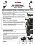
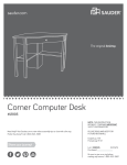
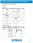
The Bowflex Xtreme® SE
Home Gym
Assembly Manual
PN 001-6980 Rev. B (10/3/06)
Congratulations on your commitment to fitness and your purchase of the Bowflex Xtreme®
SE home gym. Before assembling your Bowflex Xtreme® SE home gym please read the Assembly
Manual and follow the Important Safety Precautions. For information on how to use your Bowflex
Xtreme® SE home gym refer to the Bowflex Xtreme® SE Owner’s Manual. Nautilus, Inc.
16400 S.E. Nautilus Drive
Vancouver, Washington, USA 98683
1-800-NAUTILUS (1-800-628-8458)
Fax (800) 898-9410
Nautilus.com
Bowflex.com
Table of Contents
Specifications / Approvals . . . . . . . . . . . . . . . . . . . . . . 1
Important Safety Precautions. . . . . . . . . . . . . . . . . . . . 2
Getting To Know Your Machine . . . . . . . . . . . . . . . . . 3
Parts Reference Guide. . . . . . . . . . . . . . . . . . . . . . . . . . 4
Hardware Guide . . . . . . . . . . . . . . . . . . . . . . . . . . . . . 7
Assembly Guide . . . . . . . . . . . . . . . . . . . . . . . . . . . . 8-18
Important Contact Numbers . . . . . . . . . . . . . . . . . . . 19
Specifications / Approvals
Product Specifications:
Product Weight
157 lbs. (71 kg)
Product Dimensions
53" (135 cm) long x 49" (124 cm) wide x 82" (208 cm) high
Workout Area
96" (244 cm) long x 78" (198 cm) wide
Number of Exercises
Over 60
Power Rod® Resistance
210 lbs. (95 kg)
Power Rod® Upgradability
310 lbs. (141 kg.)
410 lbs. (186 kg.)
User Weight Limit
300 lbs. (136 kg)
Regulatory Approvals:
Meets:
EN957-1 Class H
EN957-2 Class H
!34-&
!34-&
US
Meets:
ASTM F2276-05
ASTM F2216-05
US
53
Bowflex Xtreme® SE Assembly Manual
Important Safety Precautions
IMPORTANT SAFETY INSTRUCTIONS
The following definition applies to the word “WARNING” found throughout this manual:
7! 2 . ) . '
Used to call attention to POTENTIAL hazards that could
result in personal injury or loss of life.
$!.'%2
!4 4 % . 4 ) / .
Read all instructions
before using the machine.
)--%$)!4%!#4)/.2%15)2%$
#!54)/.
7! 2 . ) . '
For your safety, perform
all assembly steps in the
sequence given. Improper
assembly can lead to injury.
$!.'%2
7! 2 . ) . '
! 4components
4 % . 4can
) /be.
Some
heavy or awkward to handle.
Get help if necessary.
$!.'%2
)--%$)!4%!#4)/.2%15)2%$
! 4 4#% !
.54 4) /) /..
)--%$)!4%!#4)/.2%15)2%$
#!54)/.
Bowflex Xtreme® SE Assembly Manual
Getting to Know Your Machine
Before You Assemble
Basic Assembly Principles
Please take the time to read all assembly
instructions before attempting to assemble your
Bowflex Xtreme® SE home gym. Select where you
are going to locate your machine carefully. The best
place for your Bowflex Xtreme® SE home gym is on
a hard, level surface. Here are a few basic tips that will make your
assembly of the Bowflex Xtreme® SE home gym
quick and easy. By using these principles, you can
simplify each process and save yourself extra time
and effort.
Select a workout area that provides a minimum
clearance behind the rod box of 0.5 ft (15 cm) and
a total width of 6.5 ft (2.0 m). Allow a minimum of 3.0 ft (0.9 m) free space in front of the machine.
1. To make the assembly process go faster,
gather the pieces you need for each step and
thoroughly read the assembly instructions for
that step prior to starting assembly for the step.
2. When tightening a locknut on a bolt, use a
combination wrench to grip the locknut and
ensure that it is fastened securely.
3. When attaching two pieces, gently lift and look
through the bolt holes to help guide the bolt
through the holes.
4. As a general rule, and for all bolts and nuts on
your Bowflex Xtreme® SE home gym, turn bolts
or nuts toward the right to tighten and left to
loosen. Or you can remember the mnemonic:
“Righty tighty, lefty loosey.”
Important: Leave all Cables coiled and wrapped until your
Bowflex Xtreme® SE Home Gym is fully assembled.
Bowflex Xtreme® SE Assembly Manual
Parts Reference Guide
8
27
49
50
48
51
43
44
7
27
43
44
15
16
26
16
28
16
16
28
16
26
39
10
28
24
24
22
16
40
22
19 20
22
27
29
37
13
22
20
29
11
16
10
28
24
117
15
15 16
11
46
16
16
5
47
16
5
1
47
16
15
1
1
16
3
2
3
2
1
1
Optional Leg Extension Attachment
.
37
If you ordered37the.
36
optional Leg Extension.
35
3734
Attachment,
.
37
31
you will receive31the .
36
38
38
37
additional .
parts shown
36
36 here.
36
35
36
32
42
36
37
45
37
30
33
32
30
3533
35
45
34
42
36
21
25
46
1
16
4
12
21
25
16
4
12
1716
15
19
14
16
14
27
39
24
13
16
16
60
27
41
40
37
16
51
9
41
50
9
15
60
27
49
48
18
7
18
8
37
Bowflex Xtreme® SE Assembly Manual
Parts Reference Guide
ITEM
QTY.
1
4
2
1
3
DESCRIPTION
ITEM
QTY.
FOOT, END CAP, FRAME
26
2
TS 0.500-13X9.5X.625X.750 BLK
BASE FRAME
27
5
LOCK NUT 0375-16 G2
1
RIGHT FRAME RAIL
28
4
LOCK NUT 0500-13 G2
4
1
LEFT FRAME RAIL
29
1
LOCK KNOB
5
1
REAR CROSSMEMBER
30
1
CAP, BOLT COVER, PLASTIC
6
1
ABDOMINAL BRACKET
31
1
7
1
LAT CROSS BAR W/ PULLEYS
BUTTON HEAD CAP SCREW .
.375-16X3X1
8
1
UPPER LAT TOWER
32
2
FW-TYPE B-R 0.375-BLK
9
1
RIGHT PULLEY ARM
33
1
NUT, NYLOCK 3/8-16
10
1
LEFT PULLEY ARM
34
1
11
1
LOWER LAT TOWER FRAME
LEG EXTENSION BACKBONE
ASSEMBLY
12
1
SQUAT PULLEY FRAME 35
2
CHROME TUBE, FOAM ROLLER
13
1
SEAT BACKBONE
36
4
FOAM ROLLER
14
1
SEAT SUPPORT RAIL
37
4
END CAP, 3/4 INCH
15
4
PULLEY SLIDER
38
1
PIN, BALL DENTENT, LEG EXT
16
22
BUTTON HEAD CAP SCREW.
0375-16X0.75 G2
39
1
BOWFLEX ROD PACK 210#
40
1
XTREME SE SEAT ASSEMBLY
41
1
XTREME SE SEAT BACK ASSEMBLY
42
1
LEG EXTENSION ASSEMBLY PIVOT
TUBE
43
1
BAR 50” BENT LAT BAR
44
1
BAR 48” LONG WITH FOAM GRIPS
45
1
ACC BAG LEG #1 ASSEMBLY
46
1
PVC HANDGRIP PAIR ASSEMBLY
47
1
AB CRUNCH STRAP ASSEMBLY
48
1
BRKT, AB CRUNCH
49
2
BUTTON HEAD CAP SCREW.
.0375-16X2.75 G2-BlkO
50
4
FLAT WASHER 0375 NARROW
51
1
XTREME SE AB BRKT TUBE ASSY
17
1
BUTTON HEAD CAP SCREW .
0375-16X5 G2
18
2
BUTTON HEAD CAP SCREW .
0375-16X3 G2
19
2
BUTTON HEAD CAP SCREW .
03125-18X2.5 G2
20
4
BUTTON HEAD CAP SCREW .
03125-18X0.75 G2
21
3
FLAT WASHER 0250
22
6
FLAT WASHER 0313
23
32
FLAT WASHER 0375
24
4
FLAT WASHER 0500
25
3
PHILLIPS SCREW 0250-20X1
Bowflex Xtreme® SE Assembly Manual
DESCRIPTION
Parts Reference Guide
Base Frame
Left Frame Rail
Right Frame Rail
Lower Lat Tower
Frame
Rod Box w/ Rods
Seat .
Support .
Rail
Squat Pulley Frame
Seat Backbone
Seat Back
Upper Lat Tower
Lat Cross Bar with
Pulleys
2 Squat Straps
8 Snap Hooks
Rear Cross .
Member
Right and Left Pulley Abdominal Bracket
Arms
2 Hand Grips
Seat
Bottom
50" Bent Lat Bar
Squat Bar
Abdominal Crunch. Tools Included:
Shoulder Harness
2 Allen Wrenches
7/32”
3/16”
NOTE: Specifications Subject to Change Without Notice
Optional Leg Extension Parts
Lock Knob
eg Extension
L
Backbone
2 Chrome
Tubes (3/4")
4 Foam Rollers
4 End Caps (3/4")
2 Snap Hooks .
& 2 Cables
NOTE: Specifications Subject to Change Without Notice
Bowflex Xtreme® SE Assembly Manual
Hardware Guide
Tools you will need:
You will need the tools listed below to complete the assembly of your Bowflex Xtreme® SE
home gym. If you don’t have these tools, you can find them at any hardware or department
store.
• 7/16" Combination Wrench
• 9/16" Combination Wrench
• Adjustable Wrench
• Socket Wrench Set
• Phillips Screw Driver
• Flat Blade Screw Driver
• Rubber Mallet
• Utility Knife
• Scissors
• A llen wrenches (included)
(NOTE: Drawings not to scale.)
Button Head Screws:
Qty: 4
(5/16" x 3/4")
Qty:2
(5/16" x 2 1/2")
Qty: 20
(3/8" x 3/4")
Qty: 2 (3/8" x 1") (in separate
bag with washers)
Qty: 2
(3/8" x 3")
Qty: 1
(3/8" x 5")
Flat Washers:
Qty: 2
(3/8" x 2 3/4")
Qty: 4
(1/2")
Self Threading Screw:
Qty: 32
(3/8")
Qty: 3
Self Threading Screws (#10 x 1")
Qty: 6
(5/16")
Qty: 3
(1/4")
Nylock Nuts:
Qty: 4
(1/2")
Bowflex Xtreme® SE Assembly Manual
Qty: 5
(3/8")
Qty: 2 Threaded Studs.
(1/2" x 9 1/2")
Assembly Guide
Step 1 Base Frame Assembly
Parts:
• Base Frame
• Left Frame Rail
• R ight Frame Rail
• Rear Cross Member
Button Head Screws
Hardware:
Flat Washers
6 Button Head Screws ( 3/8" X 3/4")
• • 6 Flat Washers (3/8")
Left Frame Rail
Tool: 7/32" Allen Wrench .
Button Head
Screws
(or Hex Wrench)
Rear Cross
Member
Flat
Washers
1-1 Lay all parts on floor as
shown.
1-2 Insert Frame Rail .
connectors into the .
Base Frame and .
Rear Cross Member. .
Secure with screws .
and washers as shown.
Base Frame
Right Frame Rail
Flat Washers
Button Head Screws
Finger tighten screws
at this time.
Step 2 Lower Lat Tower Assembly
Parts:
• Lower Lat Tower Frame
• Rod Box with Power Rod® Pack
Lower Lat Tower Frame
Hardware:
• 3 Self Threading Screws (#10 X 1")
• 3 Flat Washers (1/4")
Tool: Phillips Screw Driver
2-1 Lay parts on floor as shown. Firmly slide Rod Box into Lower
Lat Tower Frame.
2-2 Fasten the Rod Box to the .
Lower Lat Tower Frame with .
screws and washers as shown. .
Tighten screws until snug.
Rod Box w/ Rods
Flat Washers
Self Threading
Screws
Bowflex Xtreme® SE Assembly Manual
Assembly Guide
Step 3 Install Lower Lat Tower Assembly
Parts:
Lower Lat Tower
Assembly
Button
Head
Screw
• Lower Lat Tower Assembly
• Base Frame Assembly
Hardware:
Button
Head
Screw
• 2 Button Head Screws (3/8" X 3/4")
• 2 Flat Washers (3/8")
Flat
Washer
Tool: 7/32” Hex Wrench
Flat
Washer
3-1 A lign the Lower Lat Tower Assembly over .
the Base Frame. Push the bottom of the Lower
Lat Tower onto the connector of the Rear Cross
Member as shown.
3-2 Secure Lower Lat Tower Assembly .
using screws and washers as shown. Base Frame
Assembly
Finger tighten screws at this time.
Step 4 Install Seat Support Rail
Flat
Washer
Seat Support Rail
Parts:
• Seat Support Rail
• Base Frame Assembly
Hardware:
• 2 Button Head Screws (3/8" X 3/4")
• 2 Flat Washers (3/8")
Tool: 7/32" Hex Wrench
4-1 Slide the bottom of the Seat Support
Rail onto the Base Frame connector
as shown.
4-2 Slide the top of the Seat Support
Rail onto the Lower Lat Tower
Assembly connector as shown. Secure using screws and washers .
as shown. Finger tighten screws at this time.
Bowflex Xtreme® SE Assembly Manual
Base Frame/ .
Lower Lat Tower
Assembly
Button
Head
Screw
Flat
Washer
Button
Head
Screw
Assembly Guide
Button Head
Screws
Step 5 Install Squat Pulley Frame
Parts:
• Squat Pulley Frame Assembly
• Main Assembly
Flat
Washers
Squat Pulley
Frame
Hardware:
Flat
Washers
• 1 Button Head Screw (3/8" X 5")
• 1 Nylock Nut (3/8")
• 2 Button Head Screws (3/8" X 1")
• 4 Washers (3/8")
Nylock
Nut
Tools: 7/32" Hex Wrench & Adjustable .
Button
Head
Screw
or Socket Wrench
5-1 Place the Squat Pulley Frame behind the Seat
Support Rail and align the top screw holes. Secure using a 3/8" X 5" screw, washer and
nut in the top hole as shown.
5-2 Install screws and washers into the bottom
holes of the Squat Pulley Frame as shown. Step 6 Install Pulley .
Arms
Left Pulley Arm
Parts:
Right Pulley Arm
• R ight Pulley Arm
• Left Pulley Arm
• Main Assembly
Hardware:
• 4 Washers (3/8")
• 4 Button Head Screws .
(3/8" X 3/4")
RCLARIT
FO
HOWN
ENOTS
M
ULLEYFRA
3QUATP
Y
Washers
Button Head
Screws
Tools: 7/32" Hex Wrench
Button
Head
Screw
6-1 Slide Left and Right Pulley Arms
onto the connectors on the base
frame as shown.
3QUATPULLEYFRAMENOTSHOWNFORCLARITY
6-2 Secure Pulley Arms to Base Frame
using screws and washers as shown. Finger tighten screws
at this time.
Base Frame &
Lower Lat Tower
Assembly
Button Head
Screw
Flat Washers
Bowflex Xtreme® SE Assembly Manual
10
Assembly Guide
Step 7 Secure Pulley Arms
Hardware:
• 2 Threaded Studs (1/2" X 9 1/2")
• 4 Nylock Nuts (1/2")
• 4 Washers (1/2")
Tool: Rubber Mallet
Flat Washers
Nylock Nuts
Flat Washers
7-1 A lign the two holes in the
Threaded
Studs
Pulley Arms with those in the
Lower Lat Tower Assembly and
secure using threaded studs,
washers and nuts as shown.
Nylock Nuts
Step 8 Install Slider Pulleys
Parts:
Slider Pulley w/
Cable Assembly
• 2 Slider Pulleys with Cable Assembly
• Main Assembly
Tools: 3/16 Hex Wrench
8-1 Install a Slider Pulley onto each Pulley
Arm as shown. 8-2 Choose any of the four holes to secure.
11
Bowflex Xtreme® SE Assembly Manual
Slider Pulley w/
Cable Assembly
Assembly Guide
Step 9 Seat Assembly
Button Head
Screws
Parts:
Flat Washers
• Seat Backbone
• Seat Bottom
Hardware:
• 4 Button Head Screws (5/16" X 3/4")
• 4 Washers (5/16")
Seat Backbone
Seat Bottom
Tool: 3/16" Hex Wrench
9-1 Install the Seat Backbone to the .
underside of the Seat Pad using
screws and washers as shown.
Step 10 Leg Extension Assembly
Parts:
• Leg Extension Backbone
• 2 Chrome Tubes
• 4 Foam Rollers
• 4 End Caps
Tool: Rubber Mallet
10-1 Insert Chrome Tubes
through
End Caps
Foam Rollers
Chrome Tubes
Leg Extension
Backbone
the upper hole and one of
the lower holes in the Leg
for
Extension. (Select hole
your comfort level.)
10-2 Slide Foam Rollers onto the
Chrome Tubes and secure
with end caps. A rubber
mallet may be needed to
secure the end caps.
NOTE: The Leg Extension may be adjusted .
during workout to best suit your height .
and personal preferences.
Bowflex Xtreme® SE Assembly Manual
12
Assembly Guide
Step 11 Install Optional .
Leg Extension Assembly
Lock Knob
Parts:
• Leg Extension Assembly
• Lock Knob
Leg
Extension
Backbone
Seat
Backbone
11-1 Insert Leg Extension
Backbone into open end of
Seat Backbone as shown.
11-2 A lign one hole of the Leg
Extension with the hole in
the Seat Backbone to fit your
height and secure with the
Lock Knob as shown.
Step 12 Install Seat Assembly
Seat
Backbone
Parts:
• Seat Assembly
• Main Assembly
12-1 A lign the top two hooks on
the Seat Backbone with one
of the lower pairs of pins on
the Seat Support Rail.
12-2 Tip seat front up and slide .
hooks onto pins. Rotate seat
down and back to use.
Note: Use lower pins until the seat
back is installed. Reverse
procedure to remove seat.
13
Bowflex Xtreme® SE Assembly Manual
Seat Support
Rail
Assembly Guide
Step 13 Install Seat Back Pad
Note: The
back of the Seat Back Pad has two
pairs of holes. Select the appropriate .
set based on your height.
Parts:
• Seat Back Pad
• Main Assembly
Hardware:
• 2 Button Head Screws (5/16" X 2 1/2")
• 2 Washers (5/16")
Tool: 3/16" Hex Wrench
13-1 Position Seat Back Pad against the .
Seat Support Rail and align the .
screw holes for your height with .
those on the Seat Support Rail.
13-2 Secure Seat Back Pad to the Seat
Support Rail using screws and .
washers as shown.
Step 14 Upper Lat Tower Assembly
Flat Washers
Parts:
Upper Lat Tower
• Upper Lat Tower
• Lat Cross Bar
Hardware:
• 2 Button Head Screws (3/8" X 3")
• 2 Washers (3/8")
• 2 Nylock Nuts (3/8”)
Tool: 7/32" Hex Wrench and Adjustable Wrench
Lat Cross Bar
Button Head
Screws
14-1 A lign the two holes on the Lat Cross Bar with
those on the Upper Lat Tower as shown. 14-2 Secure using washers and screws as shown..
Bowflex Xtreme® SE Assembly Manual
14
Assembly Guide
Step 15 Ab Bracket Assembly
Parts:
• Abdominal Bracket (2 pieces)
Hardware (1:1):
• 2 Button Head Screws (3/8" X 2 3/4")
• 4 Washers (3/8")
• 2 Lock Nuts 3/8 -16
Tool: 7/32" Hex Wrench
15-1 Attach the Ab Lat Cross Bar to the Ab Bracket as shown. Button Head Cap Screw
Flat Washer
Ab Bracket
Ab Lat Cross Bar
Flat Washer
Lock Nut
15
Bowflex Xtreme® SE Assembly Manual
Assembly Guide
Step 16 Install Upper Lat Tower Assembly and
Ab Bracket
Parts:
• Upper Lat Tower Assembly
• Abdominal Bracket
• Main Assembly
Ab Bracket on
Lat Tower
Hardware (1:1):
• 6 Button Head Screws (3/8" X 3/4")
• 6 Washers (3/8")
Tool: 7/32" Hex Wrench
16-1 Slide the Upper Lat Tower Assembly onto the .
Lower Lat Tower.
16-2 Place the Ab Bracket against the Lat Tower and secure
the entire assembly with 6 washers and screws as shown.
Bowflex Xtreme® SE Assembly Manual
16
Assembly Guide
Step 17 Tighten Hardware
17-1 Carefully go over the entire Bowflex Xtreme® SE home gym and tighten
all hardware before proceeding to the next step. Pay close attention to
the hardware installed in Steps 1, 3, 4, and 6. Step 18 Connecting Cables
Parts: Completed Bowflex Xtreme® SE home gym
Tool: Scissors or other cutting tool (not included)
18-1 Remove the wrapping from around the coiled cable and
pulley attached to the Right and Left Frame Rails. 18-2 R
emove the wrapping from around the coiled cable and
pulley attached to the left and right side of the lat tower.
18-3 Attach the cable to the home gym following the routing for
the various exercise positions. NOTE: A s you use your home gym, you will connect the cables
and pulleys in a variety of ways to perform the exercises. Refer to the Owner’s Manual for information on using
the Bowflex Xtreme® SE home gym..
Chest Exercises
17
Bowflex Xtreme® SE Assembly Manual
Lat Pulldown Exercises
Abdominal Exercises
Leg and Squat Exercises
Assembly Guide
Step 19 CONGRATULATIONS!
You have successfully completed assembly of your Bowflex Xtreme® SE home gym! Please
inspect your machine to ensure that all fasteners are tight and components are properly
assembled. Review all warnings affixed to machine.
7! 2 . ) . '
Failure to visually check and test assembly
before use can cause damage to the Bowflex
Xtreme® SE home gym and serious injury to
users and bystanders and can also compromise
the effectiveness of your exercise program.
$!.'%2
!4 4 % . 4 ) / .
)--%$)!4%!#4)/.2%15)2%$
#!54)/.
Bowflex Xtreme® SE Assembly Manual
18
Important Contact Numbers
If you need assistance, please have both the serial number of your machine and the date of
purchase available when you contact the appropriate Nautilus office listed below.
OFFICES IN THE UNITED STATES:
E-mail: [email protected]
• NAUTILUS INNOVATION CENTER
Nautilus, Inc.
1886 Prairie Way
Louisville, Colorado, USA 80027
Vancouver, Washington, USA 98683
Phone: 800-NAUTILUS (800-628-8458)
Email: [email protected]
Fax: 800-898-9410
• TECHNICAL/CUSTOMER SERVICE
Nautilus, Inc.
World Headquarters
16400 SE Nautilus Drive
Vancouver, Washington, USA 98683
Phone: 800-NAUTILUS (800-628-8458)
Email: [email protected]
Fax: 877-686-6466
• CORPORATE HEADQUARTERS
Nautilus, Inc.
World Headquarters
16400 SE Nautilus Drive
Vancouver, Washington, USA 98683
Phone: 800-NAUTILUS (800-628-8458)
INTERNATIONAL OFFICES:
For technical assistance and a list of distributors in your
area, please call or fax one of the following numbers.
• international CUSTOMER SERVICE
Nautilus International S.A.
Rue Jean Prouvé 6
1762 Givisiez / Switzerland
Tel: + 41-26-460-77-77
Fax: + 41-26-460-77-70.
Email: [email protected]
BUSINESS OFFICES:
• Switzerland Office
Nautilus Switzerland S.A.
Tel: + 41-26-460-77-66
Fax: + 41-26-460-77-60.
• GERMANY and AUSTRIA OFFICE
Nautilus GmbH
Tel: +49-2204-610-27
Fax: +49-2204-628-90
.
• ITALY OFFICE
Nautilus Italy s.r.l.
Tel: +39-051-664-6201
Fax: +39-051-664-7461.
• United Kingdom OFFICE
Nautilus UK Ltd.
Tel: +44-1908-267-345
Fax: +44-1908-267-346
• china OFFICE
Nautilus Representative Office
Tel: +86-21-523-707-00
Fax: +86-21-523-707-09
19
Bowflex Xtreme® SE Assembly Manual
© 2006 Nautilus, Inc. All Rights Reserved.
Nautilus, Inc. World Headquarters, 16400 S.E. Nautilus Drive, Vancouver, Washington USA 98683 1-800-NAUTILUS (1-800-628-8458)
Bowflex, Bowflex Xtreme, Power Rod and the Bowflex logo are either registered trademarks or trademarks of Nautilus, Inc. All other
trademarks are trademarks of their respective companies.
Printed in China