1
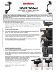
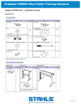
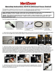
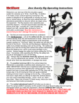
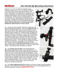
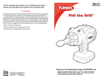
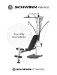
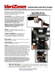
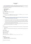
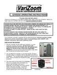
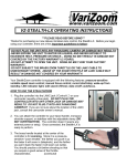
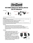
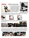
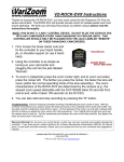
VZ-MC100
Pan and Tilt Head - Set-Up and Operating
Instructions
PLEASE READ THOROUGHLY BEFORE STARTING! SAFETY PRECAUTIONS: *Keep fingers and loose clothing
away from gears and moving parts. *Always unplug VZ-MC100 Pan and Tilt Head when not in use. *Mount only
on stable surfaces.
***Turn off your camera’s Optical Image Stabilizer while it is mounted to the MC100***
SETTING UP YOUR NEW PAN AND TILT HEAD –
1. Bolt the base plate of the VZ-MC100 head securely to jib or tripod mount. The base is
designed to mount on a flat surface or 100mm bowl, so an adapter may be necessary for
other sizes (consult jib or tripod maker). The mounting plate on the MC100 has a threaded
hole, but it should never be used without the included nut and washer to ensure that the
head does not fall!
Pan and Tilt Motor Attachment
2. There are two motors included, one for Panning left/right (to place at the base of the
MC100), and one for Tilting up/down (to place at the top).
The motors are easily attached by a.) loosening the clamp lever and sliding the clamp
onto the stainless steel post adjacent to the large black arm gears. b.) connecting the
male stereo plug from the motor to the female plug on MC100 head and
For initial setup, leave the motors disengaged (the small brass motor gears
should be pulled away from the large black gears).
HORIZONTAL CAMERA BALANCING
3. There are 2 steps to balancing the camera – horizontal and vertical - this is just the first
step, the horizontal balancing, which is quite simple.
Securely attach the camera to the mounting plate with bolt and washer. After tightening
the bolt, slightly loosen it again so that the camera may slide forward and backward on the
mounting plate.
Move the camera so that gravity allows it to rest on the plate without tilting up or down,
balancing the camera horizontally. The tilt arm that holds the
adjustable mounting plate should be exactly parallel to the
main arm (straight up). Now you can thoroughly tighten the
camera mounting bolt(s) so that the camera doesn’t slide
when tilting (you may want to use multiple bolts for large
cameras with tripod mounting plates).
CAMERA MUST BE PROPERLY BALANCED FOR
OPERATION.
1
Bad Horizontal
Balance
Good Horizontal
Balance
VERTICAL CAMERA BALANCING
4. The second step of balancing the camera is the vertical balancing, which is a
little more involved and less intuitive.
As you may have noticed, the camera platform adjusts up and down along
the two support rods (pictured at right). The two levers on either side of the
platform must be loosened to make the adjustment – DO NOT LOOSEN AT
THIS TIME. These levers can be repositioned without loosening or tightening
by simply pressing on the button and lifting the lever, then rotating it. When
you want to loosen or tighten the lever, simply rotate it normally (“lefty
loosey, righty tighty”).
With the camera horizontally balanced, rotate the platform so the camera is
exactly vertical. Be sure to keep the gears disengaged.
1
If the camera stays vertical, it is pretty close to vertically balanced.
If the camera platform swings down, the camera is too low and you
need to slide it upward (1). Loosen levers and adjust.
2
If the camera platform swings up, you need to slide it downward (2).
Loosen levers and adjust.
It is easier to adjust the camera platform with the camera pointing up (the rods horizontal, as pictured above),
as you won’t have to support the weight of the camera while you adjust the platform position.
If the camera stays vertical, go ahead and tighten the levers.
NOW TILT THE CAMERA AT VARIOUS ANGLES ALL THE WAY AROUND – IT SHOULD HOLD ANY POSITION
IF PROPERLY BALANCED. YOU MAY NEED TO TWEAK THE HORIZONTAL AND VERTICAL POSITIONS TO
GET IT EXACTLY RIGHT.
A BALANCED CAMERA WILL HOLD ANY POSITION THROUGH 360 DEGREES WITHOUT THE MOTORS
ENGAGED. THE CAMERA MUST BE THOROUGHLY BALANCED FOR PROPER OPERATION.
5. Engage the brass motor gears to the large black gears on the arm
and tighten. Be sure the levers are pointing away from the rotating
arm.
-NOTE: Once tightened, you can adjust the position of the lever by
simply pulling out on it and then rotating the lever until it faces
away. This will NOT loosen the fastener. Failure to aim lever
away will impede the movement of the MC100.
2
Connecting the Cables
1.
Connect the locking 4-pin control cable to the 4-pin motor cord at the
base of the MC100.
2.
Connect the other end of the 4-pin control cable to the
MC100 Control Unit at the locking 4-pin connector.
The additional 3-pin port located beneath the motor cable port
will provide 24VDC output.
3.
Connect the 4-pin XLR power cable from the AC adapter to the
4-pin XLR power connector located on the MC100 Control Unit.
OPERATION OF MC100 CONTROL UNIT
1.
The joystick controls the head in an intuitive manner. You can change the
direction of the pan response by flipping the switch “L” to “R”, while the
middle position of the switch “OFF” will put the motor into neutral. This
OFF position is very helpful in situations where you want to prevent motion
or to pan without tilting (or vice-versa). You can also change the direction
of the tilt response by flipping the switch “Up” to “Dn”, while the middle
position of the switch “OFF” will put the motor into neutral.
Also note the silver dials for changing the maximum pan and tilt speeds.
You may want to keep these turned up at least 1/3 of the way for best
operation.
Overslung/Underslung Operation
When switching between overslung and underslung, the left-right (pan)
response of the joystick will be flipped. The toggle switch on the control box
allows you to reverse the left-right response of the joystick.
3
In addition to the joystick, which is pressure-sensitive for speed control, these dials enable the operator to set the
maximum speed of each motor, allowing for a higher degree of control.
Turn the dials completely clockwise for maximum speed. The most effective way to vary the speed of the panning
and tilting is by using the joystick, but you can also preset the maximum speed using the dials.
***The control box operates most effectively with the speed dials turned up at least
1/3 of the way (“10 o’clock”). We don’t recommend turning the dials all the way down.
You may experience drifting issues with the dials turned too far down.***
IMPORTANT NOTES *
* STORAGE
We recommend removing the motors from the Pan/Tilt head when storing the MC100 unit in the case. You can do this by
loosening the clamp levers and sliding the motors off the stainless steel mounting posts. The unit will be safer to handle
and easier to put in the case without the motors attached. Likewise, you should disconnect all extension cables from the
unit and store them in a properly coiled position. When storing the unit, do not subject it to excessive heat, moisture or
dust – store in a cool, dry place for optimal long-term performance.
* TRIPOD MOUNTING
We recommend mounting the MC100 on a 100mm bowl-type tripod since it will fit snugly and enable you to thread the
supplied bolt through the MC100 mounting plate and down through the bowl of the tripod. Using the supplied oversize
washer and nut, you can securely bolt the MC100 onto the tripod bowl. Although the MC100 can be mounted to a
standard center-post tripod, the mounting bolt on such tripods isn’t long enough to enable you to secure the mount with a
washer and nut. If the tripod/MC100 mount were suddenly jarred or disrupted, there is a possibility the mounting bolt
might bend or shear, so be very cautious about this type of setup. VARIZOOM DOES NOT RECOMMEND MOUNTING
THE MC100 ON ANY TRIPOD OTHER THAN A 100 mm BOWL TRIPOD.
* 360-DEGREE PANS AND TILTS
The MC100 is capable of 360-degree turns on either axis, and the only limitation is in the twisting of your cables.
Typically, you can go at least 360 degrees before the cables become severely entwined, but you should always be aware
of the stress you place on the cables when going past 360 degrees – cable damage may result. Furthermore, improper
cable management may result in damage to the camera’s connectors, so be aware of cable twist when rotating beyond
360 degrees of movement.
4
TROUBLESHOOTING: UNWANTED CAMERA MOVEMENT
1-TURN OFF YOUR CAMERA’S OPTICAL IMAGE STABILIZER (OIS) WHILE IT IS MOUNTED TO THE PAN/TILT
HEAD. OIS DOES NOT REACT WELL TO PAN/TILT SYSTEMS.
2-TURN THE SPEED DIALS UP
3-MAKE SURE your camera is perfectly balanced by disengaging your motors and tilting the camera at various angles – it
should not move at all if the camera is in balance (if necessary, re-balance – see Page 1).
4- IF SOLUTIONS 1-3 DON’T WORK, you may have motor drift - do not worry! To find out if you have motor drift, do the
following: *** turn the speed dials all the way up for both pan and tilt, and with all of the power and control cables
connected (a mounted camera is not necessary), disengage the motors so that the brass gears on the motors can spin
freely. If the brass gears turn on their own, without your command, the motor control joystick needs to be calibrated (if
they don’t move, the drifting must be attributed to bad balance).
If Motors Drift:
With both speed dials turned all the way
A.2.
up and the motors disengaged from the head
A.1.
so they can spin freely, remove the large
black threaded plug on the side of the control
box (A.1.) and you will see two dials for
calibrating the pan and tilt (A.2). Carefully
use a small tip Phillips or flat screwdriver to
turn the dials until the motors stop moving.
Try to center the dials between the points
where the motors begin moving in each direction. * Do not press hard on these dials or damage may result. *
5 – MOTORS DON’T MOVE – Make sure the direction switches for pan and tilt are not set to “OFF”. Make sure power is
plugged in and the motors are plugged into the connecting cables on the head. Make sure the gears are fully engaged
and locked to the head. If all of this fails, you may have a damaged cable, power supply or control box – contact VariZoom
TROUBLESHOOTING: ERRATIC CONTROL UNIT
Erratic control unit behavior may result from damaged cables or bad power connection.
MAINTENANCE:
The MC100 should not require much maintenance, but over time wear and tear may take its toll. The most common wear
and tear issue is damaged cables, which are relatively easily replaced. After much use, the bearings in the base may
need light lubrication. These bearing are the two sets of thin triple washer-like assemblies above and below the base
block (where the rotating shaft fits). If you lubricate these bearings, just use light oil and don’t add very much or you will
simply attract more dust. As long as the unit pans smoothly, you shouldn’t worry about this. Most other maintenance
should be performed by the factory.
REMINDER: KEEP FINGERS, LOOSE CLOTHING, AND
HAIR AWAY FROM MOVING PARTS AND GEARS! ALWAYS UNPLUG MC100
PAN AND TILT HEAD WHEN NOT IN USE! WHEN IN DOUBT ABOUT SAFETY,
ASK QUESTIONS FIRST!!! 512-219-7722 / www.varizoom.com
5