1
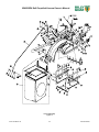
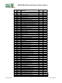
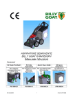
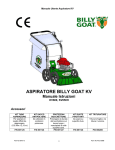
BILLY GOAT ® MV650SPH and MV600SPE Self-Propelled Vacuum Owner’s Manual Accessories Caster Kit Use on hard surface for maneuverability. P/N 840129 Part No 840245 Hose Kit For vacuuming hard to reach areas. Bag Liner Kit To collect leaves, thatch, and grass. P/N 840116 P/N 840134 1 Felt Bag Kit Use on all dusty conditions. P/N 840194 Form No F060711D MV650SPH Self-Propelled Vacuum Owner’s Manual CONTENTS Specifications and Sound/Vibration ................................................................................................................... 3 Instruction Labels ............................................................................................................................................... 4 Assembly Instructions ........................................................................................................................................ 5-8 Operation ........................................................................................................................................................... 9-13 Maintenance and Troubleshooting ..................................................................................................................... 14-18 Illustrated Parts List ........................................................................................................................................... 19-26 Go to http://www.billygoat.com for French-Canadian translations of the product manuals. Visitez http://www.billygoat.com pour la version canadienne-française des manuels de produits Part No 840245 2 Form No F060711D MV650SPH Self-Propelled Vacuum Owner’s Manual MV 650 SERIES SPECIFICATIONS MV650SPH MV600SPE Engine Type Honda GSV190AA1A Briggs and Stratton 122MO70110F1 Horsepower 6.5 (4.85 kW) 6.25 (4.66 kW) Fuel Capacity 1.6 qt (1.5 L) 1qt (.9L) Oil Capacity 0.58 qt (0.54L) 0.63 qt (0.59L) Unit Weight 179 lbs (81.2 kg) 179 lbs (81.2 kg) Shipping Weight 208 lbs (94.3 kg) 208 lbs (94.3 kg) Overall Dimensions 28” Wide x 62.5” Long x 45.5” High 28” Wide x 62.5” Long x 45.5” High Maximum Operating Slope 20 In compliance with 2000/14/EEC standards 103 dB(a) at 3320 rpm 103 dB(a) at 3320 rpm Sound at operators ear 83 dB(a) at 3320 rpm 83 dB(a) at 3320 rpm o 20 o SOUND DATA SOUND LEVEL 103 Dba at Operator Position Sound tests were conducted in accordance with 2000/14/EC as well as ISO11094, and were performed on 5-17-2005 under the conditions listed below. Sound power level listed is the highest value for any model covered in this manual. Please refer to serial plate on the unit for the sound power level for your model. General Conditions: Temperature: Wind Speed: Wind Direction: Humidity: Barometric Pressure: Sunny o o 66.2 F (19 C) 8.5 mph (13.7kph) South Southwest 59% 29.9” Hg (101.35kPa) VIBRATION DATA VIBRATION LEVEL 1.43g(14.00m/s 2) Vibration levels at the operator’s handles were measured in the vertical, lateral and longitudinal directions using calibrated vibration test equipment. Tests were performed on 5-24-2006 under the conditions listed below. General Conditions: Temperature: Wind Speed: Wind Direction: Humidity: Barometric Pressure: Form No F060711D Sunny o o 73.7 F (23.2 C) 8.05 mph (3.6m/s) South 83.5% 29.91” Hg (101.31 kPa) 3 Part No 840245 MV650SPH Self-Propelled Vacuum Owner’s Manual INSTRUCTION LABELS The labels shown below were installed on your BILLY GOAT ® MV Vacuum. If any labels are damaged or missing, replace them before operating this equipment. Item numbers from the Illustrated Parts List and part numbers are provided for convenience in ordering replacement labels. The correct position for each label may be determined by referring to the Figure and Item numbers shown. PN 400268 (See Figure 3 Item 55) PN 890254 (See Figure 4 Item 162) PN 840054 (See Figure 1 Item 34) PN 400424 (See Figure 1 Item 11) PN 810736 (See Figure 4 Item 174) PN 890301 (See Figure 4 Item 163) PN 900327 (See Figure 2 Item 118) PN 840080 (See Figure 4 Item 175) PN 500176 (See Figure 2 Item 120) ENGINE LABELS CONTROLS HONDA Throttle P/N 840045 Part No 840245 4 Drive P/N 510127 Form No F060711D MV650SPH Self-Propelled Vacuum Owner’s Manual MV Vacuum Assembly Drawing Form No F060711D 5 Part No 840245 MV650SPH Self-Propelled Vacuum Owner’s Manual PARTS LIST Part No 840245 6 Form No F060711D MV650SPH Self-Propelled Vacuum Owner’s Manual ASSEMBLY INSTRUCTIONS Your BILLY GOAT ® MV Vacuum was shipped in one carton, completely assembled except for the Hood/Upper Handle Assembly. Mounting hardware for the Hood/Upper Handle Assembly is temporarily installed on the lower handle and the Housing assembly. READ all safety instructions before assembling unit. TAKE CAUTION when removing the unit from the box since Hood/Upper Handle Assembly is attached to the unit by cables. Remove unit from carton. Make sure the following items that have been packed with unit: Parts bag P/N 840187 Owner’s Manual, P/N 840245 General Safety and Warnings Manual, P/N 100294 Declaration of Conformity, P/N 840204 Honda Engine Manual Warranty Card, P/N 400972 Ty-Wraps (2 ea) Hardware Bag DISCONNECT spark plug wire before assembling unit. 1. Attach hood assembly to the housing then hold in place during the step 2. NOTE: BE SURE ALL CABLES ARE ROUTED ON THE UNDERSIDE OF THE HOOD AND HOUSING. 2. Install item #170 center bolt first when aligned with a nut on the housing. 3. Attach rest of hood assembly to the housing using corresponding hardware. NOTE: You will have to insert the bolt/washer from the inside by reaching through the hood. 1st - Two 7/16” wrenches. Form No F060711D 7 Part No 840245 MV650SPH Self-Propelled Vacuum Owner’s Manual 4. Attach upper handle brace to lower handle using corresponding hardware. Then repeat this step on the other side. 5. Attach rod end (164) to the nozzle door rod then secure in place by tightening jam nut. 6. Attach nozzle door rod to the nozzle door using corresponding hardware. NOTE: It is easier to do this with nozzle door closed. - Two 9/16” wrenches. - Two 1/2” wrenches. 7. Attach rod end to rod (as in step 5). 9. Install cable ty wraps. 8. Attach nozzle door rod to the lever with nozzle door closed and lever in hose kit position. 10. Reconnect spark plug wire. HERE 11. Attach the bag. NOTE: Check to see nozzle door open and close all the way (see page 15). Tighten or loosen the rod end (164) for any adjustments. Two 9/16” wrenches. Part No 840245 HERE 8 Form No F060711D MV650SPH Self-Propelled Vacuum Owner’s Manual OPERATION OPERATOR CONTROLS The operator’s position is at the rear of the machine between the handlebars. The operator should STAND in a position to allow both handlebars to be grasped firmly, which allows sufficient leverage to steer the machine. Operator’s controls are shown below. 3 4 6 1 5 2 Operator Control Locations 1 2 3 Drive Clutch Lever Bag Latch Pull Starter 4 5 6 Throttle Control Drive Shifter Control Nozzle Door Adjuster STARTING CHECK engine oil level before operating machine. 1. Place equipment on a level, firm surface that is free of rocks or other debris. 2. Place throttle in START position. Throttle DO NOT START equipment without the debris bag in place. Form No F060711D 9 Part No 840245 MV650SPH Self-Propelled Vacuum Owner’s Manual 3. Secure the unit with left hand at the handle then pull starter rope with right hand to start engine. On Electric models only PULL ROPE STARTER WITH RIGHT HAND SECURE UNIT AT THE HANDLE WITH LEFT HAND DURING START PULL STARTER CORD slowly until resistance is felt. Then pull cord rapidly to avoid kickback. 4. Move throttle control back to FAST position and allow engine to reach correct operating speed. 5. For Electric models: Set the throttle to the fast position, then pull up and push forward on the start switch. Choke if needed VACUUM NOZZLE HEIGHT ADJUSTMENT FOR MAXIMUM PICKUP: Adjust nozzle height as close to debris as possible, but without blocking airflow into the nozzle. NOTE: Never bury nozzle into debris. The vacuum nozzle is raised and lowered by turning the crank handle clockwise and counterclockwise. Part No 840245 10 Form No F060711D MV650SPH Self-Propelled Vacuum Owner’s Manual VACUUM NOZZLE DOOR ADJUSTMENT The vacuum nozzle door adjusts for the maximum performance under various applications. Nozzle fully opened. This is ideal for turf application Nozzle half way opened. This is ideal for hard surface application Nozzle closed for OPTIONAL hose kit. This is ideal for hard to reach places. Form No F060711D 11 Part No 840245 MV650SPH Self-Propelled Vacuum Owner’s Manual VACUUMING OPERATION This machine is designed for vacuuming leaves, grass clippings, and other types of organic litter. Debris mixed with cans, bottles, and small amounts of sand can be vacuumed; however, it is not this machine's primary purpose. Vacuuming cans, bottles, and sand will affect the longevity of your machine. In dusty conditions it maybe necessary to purchase Felt Bag Kit (P/N 840022). Do not operate if excessive vibration occurs. If excessive vibration occurs, shut engine off immediately and check for damaged or worn impeller, loose impeller bolt, loose impeller key, loose engine or lodged foreign objects. Note: See parts list for proper impeller bolt torque specifications. (See trouble shooting section on page 23). 1. Move Shift Lever to correct position (1, 2, or 3) for desired gear. Gear Shift Lever 2. Squeeze the Drive Clutch lever against the handle to engage the drive. Drive Clutch Lever SHUT DOWN 1. Release Drive Clutch Lever to disengage the drive. 2. Pull Throttle Control all the way back to the STOP position. Part No 840245 12 Form No F060711D MV650SPH Self-Propelled Vacuum Owner’s Manual CLEARING A CLOGGED NOZZLE DISCONNECT spark plug wire before servicing unit. 1. Shut engine off and wait for impeller to stop completely. 2. Disconnect spark plug wire. 3. Wearing durable gloves, remove clog. WEAR durable gloves. Clog may contain sharp materials. 4. Reconnect spark plug wire. DEBRIS BAG Debris bags are normal replaceable wear items. Frequently empty debris to prevent bag overloading with more weight than you can lift. Bag liners are available for use in various conditions where debris will be vacuumed. (see Bag Liner Options shown on page 1). DO NOT place bag on or near hot surface, such as engine. Be sure engine has come to a complete stop before removing or emptying bag!!. This vacuum is designed for picking up trash, organic material and other similar debris (see Safety Warnings page 4-5). Many vacuums are used where dust is mixed with trash. Your unit can intermittently vacuum in dusty areas. However, following these rules will help maintain your machine's ability to vacuum in dusty conditions: •Run machine at idle to quarter throttle. •Machine or pressure-wash debris bag if normal cleaning does not fully clean bag. Bag should be thoroughly dry before use. Having one or more spare Felt Filter (840194) is a good way to reduce down time while dirty bags are being cleaned. Form No F060711D 13 Part No 840245 MV650SPH Self-Propelled Vacuum Owner’s Manual MAINTENANCE PERIODIC MAINTENANCE Periodic maintenance should be performed at the following intervals: Maintenance Operation Every Use Daily or Every 5 Hours Every 25 Hours Every 50 Hours Every 100-150 Hours z Inspect for worn or damaged parts. Check for excessive vibration z Inspect for loose parts. z z Clean Debris Bag Lubricate clutch control lever (Use white lithium grease or equiv.) LOCATION 1 z Lubricate height adjuster LOCATION 2 z z Check drive clutch cable tension. z Replace drive belts. COMMON REPLACEMENT PARTS • Bag. P/N 840189. Original equipment replacement bag. • Skid. P/N 840041. Nozzle wear guard skid. • Drive Belt P/N 840066, Original equipment replacement belt LOCATION 1 LOCATION 2 HERE HERE Apply lubricant on the zinc die cast barrel. Part No 840245 Apply lubricant on the thread. 14 Form No F060711D MV650SPH Self-Propelled Vacuum Owner’s Manual IMPELLER REMOVAL READ all safety instructions before servicing unit. DISCONNECT spark plug wire before servicing unit. Tools required: - 1/2” socket, 3/8” drive - ratchet, 3/8” - drive extension, 3/8” drive - universal joint, 3/8” drive - pry bar or long screwdriver - jack stands or similar device adequate to support weight of machine. 1. 2. 3. 4. 5. 6. 7. 8. 9. 10. 11. 12. 13. Wait for engine to cool and disconnect spark plug. Drain fuel and oil from the engine. Remove belt cover by removing 5 screws. Detach drive belt from the transmission pulley by rotating the transmission assembly to relieve belt tension. Remove engine, impeller and mounting plate by removing bolts around outside of housing. Leaving engine fastened to plate, remove impeller bolt and lock washer and slide impeller off crankshaft ( A puller may be required). CAUTION: Do not drop impeller. If impeller does not slide off crankshaft, place two crowbars between impeller and housing on opposite sides. Pry impeller away from engine until it loosens. Using a penetrating oil can help loosen a stuck impeller. If the impeller cannot be loosened, obtain a 1” (25.4mm) longer bolt of the same diameter and thread type as the impeller bolt. Invert engine and impeller and support engine above ground to prevent recoil damage. Thread longer bolt by hand into the crankshaft until bolt bottoms. Using a suitable gear or wheel puller against the bolt head and the impeller back-plate (near the blades), remove impeller from shaft. To reinstall impeller, use a new impeller bolt and lockwasher Tighten impeller bolt. Torque impeller bolt to 33-38 Ft. Lbs. (45-52 N.m). Reinstall engine, impeller, and mounting plate onto housing in reverse order of removal. Before connecting spark plug wire, slowly pull engine starting rope to insure that impeller rotates freely. Reconnect spark plug wire. DRIVE CLUTCH CABLE ADJUSTMENT READ all safety instructions before servicing unit. DISCONNECT spark plug wire before servicing unit. Tools required: - Ratchet wrench with 6” extension and 3/8” socket. - Two 10mm open end wrenches. - Tape measure. Form No F060711D 15 Part No 840245 MV650SPH Self-Propelled Vacuum Owner’s Manual Procedure: 1. Wait for engine to cool and DISCONNECT SPARK PLUG! 2. Engage the clutch lever then pull the unit back until it stops freewheeling. The clutch lever should engage around 2 5/16” of travel or 4 inches from tip of lever to handle. 3. Tighten or loosen cable adjuster nut next to the clutch lever until drive engages at 4” from handle. 4. Holding the adjuster nut in place with one wrench tighten cable lock nut firmly. 5. Readjust as needed. 6. RECONNECT SPARK PLUG! 7. Test run unit to insure proper operation after this or any other maintenance procedure. 8. If clutch still will not engage at 4” from handle, remove guard retaining screws and guard. 9. Measure the amount of spring stretch. Spring should measure 1 1/8” when engaged (Lever 4” from handle). 10. Release clutch lever and then move it to engagement position again and hold it, check the spring length to assure it stayed in adjustment. 11. Re-install guard and fasteners. cable adjustment INCREASE 2 1/16” 4" from handle 1 1/8" Loosen Tighten DRIVE BELT REMOVAL AND REPLACEMENT READ all safety instructions before servicing unit. DISCONNECT spark plug wire before servicing unit. Tools required: - 3/8” drive ratchet - 3/8” and ½” socket wrenches - 3/8” and 5/16” wrench Procedure: 1. Wait for engine to cool completely and DISCONNECT SPARK PLUG. 2. Remove guard fasteners and guard. 3. Remove throttle control cable from engine. 4. Unplug wiring harness wire at engine. 5. Tilt transmission input pulley toward engine and remove the belt from it upward. 6. Remove all six screws fastening the engine base plate to the housing. 7. Lift engine assembly from housing. 8. Slide belt inward under the engine and off downward around impeller. 9. Install new belt in reverse order of belt removal. 10. Note: before placing new belt on transmission pulley look under the engine to insure the belt is properly in the groove of the engine pulley. 11. Install engine assembly in reverse order of removal. 12. RECONNECT THE SPARK PLUG Part No 840245 16 Form No F060711D MV650SPH Self-Propelled Vacuum Owner’s Manual INSTALLING NEW DRIVE CHAIN/ALIGNMENT/TENSION READ all safety instructions before servicing unit. DISCONNECT spark plug wire before servicing unit. Tools required: - 7/16” and 1/2” socket. 7/16” and 1/2” combination wrench. “Needle nose” pliers Flat head screwdriver Allow the engine to cool completely and DISCONNECT THE SPARK PLUG. 1. Unfasten and remove the guard. 2. Rotate left rear wheel to bring the chain “master link” into view on the axle sprocket. 3. Using the needle nose pliers carefully remove master link retaining spring clip. 4. Slide the master link from the chain and remove the chain. 5. Thread the new chain onto the sprockets, place the ends of the chain on the axle sprocket, this makes it easier to hold the chain in place when you slide the new master link in place. 6. Install the new master link and CAREFULLY install the retaining clip. 7. Rotate left rear wheel to find the location where the chain is tightest (there are always slight variations in the sprockets that make the chain tighter at places in its rotation). 8. Rotate the axle several times and listen for “popping” or “clacking” this indicates too much tension on the chain or misalignment of the chain. Skip to Step 12 if no “popping” or “crackling” occurs. Improper Chain Tension 9. At the point where the chain is tightest check the chain to for ¼” to ½” total slack halfway between the axle sprocket and the transmission sprocket. Skip to Step 11 if the deflection is correct. 10. Loosen 4 nuts holding the bearing bracket (see Fig 1) slide it very slightly forward to tighten the chain or slide backward to loosen. Tighten 4 nuts back then check the chain deflection. Repeat this step if necessary. Improper Chain Alignment 11. Loosen 5 bolts securing the drive system (see Fig 2) slide it left or right then check the alignment using straight edge. Tighten 5 bolts then repeat Step 8. 12. Reinstall the guard and all of its fasteners. 13. RECONNECT THE SPARK PLUG. Fig 1 Fig 2 Form No F060711D 17 Part No 840245 MV650SPH Self-Propelled Vacuum Owner’s Manual WIRING DIAGRAMS Bag Switch Circuit Schematic Diagram TROUBLESHOOTING Problem Will not vacuum or has poor vacuum performance. Possible Cause · Dirty or full debris bag or filter. Solution · Nozzle height set too high or too low. · Hose kit cap missing. · Clogged nozzle or exhaust. · Excessive quantity of debris. · Clean debris bag and filter. Shake bag clean or wash. · Adjust nozzle height (see page 14). · Check for hose kit cap. · Unclog nozzle or exhaust (see page 5) · Allow air to feed with debris. Abnormal vibration. · Loose or out of balance impeller. · Loose engine. · Check impeller and replace if required. · Check engine. Engine will not start. · Throttle in off position. · Engine not in full choke position. · Check throttle control (see page 13). · Check throttle, choke position (see page 13). · Out of gasoline or bad, old gasoline. · Spark Plug wire disconnected. · Gas valve off. · Dirty air cleaner. · Check gasoline. · Connect spark plug wire. · Turn on gas valve. · Clean or replace air cleaner. Contact a qualified service person. · Latch the bag properly or check the bag rod to see if it is bent. · Safety Interlock disengaged on bag plate. Engine is locked, will not pull over. · Impeller plugged or clogged. · Engine problem. No self-propelling · Drive clutch not engaged · Remove debris (see page 16). · Contact an engine servicing dealer for engine problems. · Engage the drive clutch lever. · Transmission not in gear. · Check transmission shift control (see page 16). · Drive belt worn or broken · Check the drive belt. · Drive clutch cable out of adjustment or broken. · Check the drive clutch cable (see page 20). Self propelled drive will not release Noisy or broken chain Part No 840245 · Spring tension too loose · Check spring legnth (see page 20). · Drive chain off the sprocket. · Check the drive chain (see page 22). · Improper drive clutch cable adjustment or cable is kinked. · No chain lubrication. · Check the drive clutch cable (see page 20). · Chain misalignment or tension. · Check the drive chain (see page 22). 18 · Lubricate chain. Form No F060711D MV650SPH Self-Propelled Vacuum Owner’s Manual ILLUSTRATED PARTS LIST Nozzle Assembly Figure 1 Form No F060711D 19 Part No 840245 MV650SPH Self-Propelled Vacuum Owner’s Manual Nozzle Assembly Parts List PART ITEM NO. NUMBER 1 350127 2 350128 3 8024060 4 8172009 5 8161042 6 8041038 7 8160002 8 8172020 9 8161044 10 8171002 11 400424 12 8024050 13 520156 14 8172011 15 840118 16 840019 17 840024 18 840101 19 840104 20 840155 21 8041004 22 840034 23 840041 24 840029 25 840073 26 840119 27 840057 28 840078 29 840158 30 840207 31 840135 32 840055 33 840035 34 840054 35 8122082 36 840088 37 8024021 38 900455 100 8172007 195 840017 201 840117 202 840198 209 8181007 211 8142001 Part No 840245 MV650SPH MV600SPE DESCRIPTION QTY. QTY. YOKE 1/2 - 20 1 1 PIN YOKE 1/2" 1 1 BOLT CARRIAGE 3/8-16X1 1/2" ZP 2 2 WASHER 3/8" SAE ZP 2 2 NUT LOCK 3/8-16 LT WT THIN ZP 2 2 SCREWCAP 5/16 -18 x 3 1/2 1 1 NYLON INSERT LOCKNUT 5/16-18 UNC 3 3 WASHER FLAT FENDER 5/16 1 1 NYLON INSERT LOCKNUT 1/2-13 UNC THIN 2 2 WASHER 1/4" FC ZP 3 3 LABEL WARNING OPEI 1 1 BOLTCARRIAGE 5\16-18X3 1\2 2 2 ROLL PIN 1/4 X 1 LONG 2 2 WASHER 1/2" SAE ZP 2 2 NOZZLE MV VAC ASSEMBLY 1 1 CAP 5 IN HOSE VAC 1 1 HANDLE LOWER MV VAC 1 1 WHEEL 14" ASSEMBLY WITH BEARING AND TIRE 2 2 AXLE FRONT WA MV VAC 1 1 BRACKET HGT ADJ WA W/LABEL MV VAC 1 1 SCREWCAP 1/4 - 20 x 0.75 HWH 1 3 LINK HGT ADJ MV VAC 1 1 BRACKET NOZZLE WEAR GUARD MV VAC 2 2 ROD CONNECT HGT ADJ 1 1 BUSHING 0.5" ID 0.625 OD X X 0.250 1 1 ROD HANDLE CRANK ASSEMBLY 1 1 HANDLE CRANK 0.5 ID X 3.72 LONG 1 1 BUSHING 3/8" ID 1/2" OD X 3/8" LONG 2 2 WASHER LOCK 1/4" TWISTED TOOTH 1 1 NUT PAL 0.5" ID x 0.75 OD 2 2 NOZZLE COVER MV VAC 1 1 LABEL PRODUCT DECAL MV 1 1 SCREW PLASTIC 5/8 8 8 LABEL HGT ADJ MV VAC 1 1 SCREW SELF-TAP 5/16 NC X 3/4 HEX 2 4 BRACKET NOZZLE COVER REINFORMENT MV 1 1 BOLT CARRIAGE 1/4-20X0.75 3 3 NUT FLANGE 1/4-20 3 3 WASHER 1/4" SAE ZP 4 MV WHEEL BEARING 2 2 SOLENOID ELEC START 1 BRACKET SOLENOID MOUNT MV 1 WASHER LOCK 1/4" EXT TOOTH 2 NUT 1/4" FIN HEX ZP 2 20 Form No F060711D MV650SPH Self-Propelled Vacuum Owner’s Manual Drive /Rear Axle Assembly Figure 2 Form No F060711D 21 Part No 840245 MV650SPH Self-Propelled Vacuum Owner’s Manual Drive /Rear Axle Assembly Parts List ITEM NO. 80 81 82 83 84 85 86 87 88 89 90 91 92 93 94 95 96 97 98 99 100 101 102 103 104 105 106 107 108 109 110 111 112 113 114 115 116 117 118 119 120 121 122 123 124 125 158 195 203 204 205 Part No 840245 PART NUMBER 840110 350133 840009 840086 840010 840085 510126 840066 510125 840011 520025 8041004 430298 840102 8024021 840028 8024060 840087 840027 840158 8172007 8160001 8041036 8160002 8041026 8172009 890359 8122082 840072 800242 8171002 8172015 510180 350146 840213 DESCRIPTION BRACKET TRANS MOUNT WA MV VAC BEARING 3/4" W/PILLOW BLOCK DIFFERENTIAL 54 TOOTH D-CUT BRACKET TRANS ANTI ROTATION MV GUARD DRIVE SP VAC TRANSMISSION 3 SPD GENERAL TRANS. SPROCKET 8 TOOTH BELT 3L34 BEARING 1/2" CLIP PLATE TRANS BEARING MOUNT MV VAC WASHER LOCK INTERNAL TOOTH 1/2" 1/4 - 20 x 0.75 HWH WASHER 5/16 LOCK TWISTED TOOTH WHEEL 14" ASSEMBLY DRIVE MV VAC BOLT CARRIAGE 1/4-20X0.75 BRACKET TRANS REINFORCE MV VAC CARRIAGE BOLT 3/8 - 16 X 1 1/2 PULLEY IDLER 2" OD X 3/8" ID TUBE 0.75 ID WHEEL SPACER SP MV VAC WASHER LOCK 1/4 TWISTED TOOTH WASHER 1/4" SAE ZP NYLON INSERT LOCKNUT 1/4-20 UNC SCREWCAP 5/16"-18X3" HCS ZP NYLON INSERT LOCKNUT 5/16-18 UNC SCREWCAP 5/16"-18 X 3/4" LONG ZP WASHER 3/8" SAE ZP 1/4 - 20 x 5/8 HWH SCREW SELF-TAP 5/16 NC X 3/4 HEX CHAIN #41 X 42 PITCH SPRING TENSION WASHER 1/4" FC ZP WASHER 3/4" SAE ZP WOODRUFF KEY 1/8 X 1/2 CLIP 1/2" SCREWCAP 1/4-20 X 5/8 GR. 5 MV650SPH MV600SPE QTY. QTY. 1 1 2 2 1 1 1 1 1 1 1 1 1 1 1 1 2 2 2 2 1 1 1 1 2 2 2 2 4 4 1 1 1 1 1 1 1 1 1 1 14 14 6 6 4 4 4 4 2 2 2 2 2 2 2 2 1 1 1 1 8 8 2-6 2-6 1 1 3 3 4 4 8171006 WASHER 1/2" FLAT CUT 3 3 900327 LABEL DANGER GUARD 8161042 NUT LOCK 3/8-16 LT WT THIN ZP 1 1 1 1 2 2 2 2 4 2 - 2 2 4 2 2 1 1 1 840188 BRACKET BEARING FIX 8041022 8172020 8177010 8041006 840017 804170 840095 840228 CARRIAGE BOLT 1/4 - 20 X 1 ZP WASHER FENDER 5/16 SPLIT LOCK WASHER 1/4" SCREWCAP 1/4"-20 X 1" HCS ZP MV WHEEL BEARING BATTERY 12 V BATTER HOLD DOWN CABLE HARNES ELECTRIC START ONE PIECE 22 Form No F060711D MV650SPH Self-Propelled Vacuum Owner’s Manual Engine Assembly Figure 3 Form No F060711D 23 Part No 840245 MV650SPH Self-Propelled Vacuum Owner’s Manual Engine Assembly Parts List ITEM NO. 50 51 52 53 54 55 56 57 58 59 60 61 62 63 64 65 66 67 80 81 205 210 Part No 840245 PART NUMBER 840069 840136 840107 840205 440153 DESCRIPTION ENGINE HONDA 6.5 VERTICAL GSV190 IMPELLER ASSEMBLY SP MV VAC PLATE TOP WA SP MV VAC HOUSING PLASTIC VAC WASHER 1.5 OD X .453 ID X .25 THK MV650SPH MV600SPE QTY. QTY. 1 1 1 1 1 1 1 1 1 1 9201087 8177012 SQ KEY 2.125 X .187 WASHER LOCK 3/8" ST MED 1 1 1 1 8172007 8172019 8041004 790167 900564 8177010 WASHER 1/4" SAE ZP WASHER FENDER 1/4 ZP SCREWCAP 1/4 - 20 x 0.75 HWH SCREWCAP 3/8-24X2 3/4" W/PATCH LOCK SCREWCAP 3/8"-16X2 1/2" TAPTITE WASHER SPLIT LOCK 1/4" 6 6 6 1 3 6 6 6 6 1 3 6 840083 840215 840213 840228 100261 SPACER 1.50OD X .890ID X .5 THK TERMINAL 18-14 BLUE T-TAP SCREWCAP 1/4-20X5/8 GR. 5 CABLE HARNESS ELECT START LABEL WARNING FUEL EN/SP 1 1 6 - 1 1 6 1 1 24 Form No F060711D MV650SPH Self-Propelled Vacuum Owner’s Manual Hood Assembly Figure 4 Form No F060711D 25 Part No 840245 MV650SPH Self-Propelled Vacuum Owner’s Manual Hood Assembly ITEM NO. 57 114 115 120 130 131 132 133 134 135 136 137 138 139 140 141 142 143 144 145 146 147 148 149 150 151 152 153 154 155 156 157 158 159 160 161 162 163 164 165 166 167 168 169 170 171 172 173 174 175 178 180 184 185 186 190 191 192 193 194 200 205 206 207 208 Part No 840245 PART NUMBER 840045 840023 840063 500176 840141 840153 840196 840037 840038 840154 840152 840195 840138 840061 840062 840191 840058 840077 8024025 8171002 8160001 520018 8172005 8164005 900407 610347 8171003 8160002 610429 610348 8041032 8041011 8041006 8041031 8171004 8172007 890254 890301 400886 8041052 8160003 8041056 840197 8149003 8041004 8172019 8041018 840071 810736 840080 8024021 840214 840180 8059140 840179 840040 840139 360203 840189 840206 520116 840228 500307 840096 100262 DESCRIPTION CONTROL THROTTLE WESCON MV VAC CONTROL SHIFT WESCON MV VAC CONTOL LEVER ASSY CLUTCH SP VAC LABEL CLUTCH DRIVE HOOD ASSY W/ LABEL MV VAC BRACKET BAG CHANNEL RH W/SEAL MV VAC SEAL BAG MV VAC TUBE HANDLE BRACE RH MV VAC TUBE HANDLE BRACE LH MV VAC BRACKET BAG CHANNEL RH W/SEAL MV VAC BRACKET NOZZLE DOOR ADJ W/LABEL MV VAC BAG ASSEMBLY MV VAC BAR LIFT NOZZLE DOOR W/ GRIP MV VAC ROD LIFT NOZZLE DOOR SP VAC PLATE BAG LATCH MV VAC GRIP LEVER LIFT SWITCH INTERLOCK VAC HARNESS WIRE ASSY MV VAC BOLT CARRIAGE 1/4-20 X 1.75 WASHER 1/4" FC ZP NYLON INSERT LOCKNUT 1/4-20 UNC SCREW HEX HEAD #10-24 X 1" WASHER #10 SAE ZP NYLON INSERT LOCKNUT 10-24 UNC Ty-Wrap PIN SCREW 1/4-28 WASHER 5/16 FLATWASHER Z/P NYLON INSERT LOCKNUT 5/16-18 UNC SPRING LEVER GZ FIBRE WASHER SCREWCAP 1/4-20X2" SCREWCAP 1/4"-20X2 1/4" ZP SCREWCAP 1/4-20X1" ZP SCREWCAP 5/16-18 X 1.75 ZP WASHER 3/8 FC WASHER 1/4" SAE ZP LABEL EAR EYE BREATHING LABEL READ ROD END BALL JOINT 3/8 NF SCREW CAP 3/8-16X1 1/2 ZP NYLON INSERT LOCKNUT 3/8-16 UNC SCREWCAP 3/8"-16X2 1/2" ZP SEAL BAG FRONT HOOD 20.5 LONG NUT REG 3/8-24 NF SCREWCAP 1/4"-20X3/4" HCS ZP WASHER FENDER 1/4 ZP SCREWCAP 1/4"-20X4" HCS ZP NUT ACORN 1/4-20 LABEL DANGER FLYING DEBRIS LABEL NOZZLE DOOR MV VAC BOLT CARRIAGE 1/4-20 X 3/4" BRACKET HOOD FRONT STRAIGHTENER PLATE SHIFT CONTROL ANTI ROT SCREWCAP #10-24X1 1/4" LABEL HOOD DECAL ROD BAG WA MV VAC LATCH RUBBER ASSEMBLY MV VAC PAL NUT 0.312 BAG DEBRIS MV VAC GROMMET RUBBER 5/8" OD X 3/8" ID LABEL MADE IN U.S.A. CABLE HARNESS ELECT START SWITCH BRACKET START SWITCH MV VAC LABEL START STOP EN/SP 26 MV650SPH MV600SPE QTY. QTY. 1 1 1 1 1 1 1 1 1 1 1 1 1 1 1 1 1 1 1 1 1 1 1 1 1 1 1 1 2 2 1 1 1 1 1 1 7 7 14 14 13 13 4 4 8 8 4 4 6 6 1 1 7 7 3 3 1 1 1 1 1 1 1 1 2 2 2 2 4 4 6 6 1 1 1 1 2 2 1 1 2 2 1 1 1 1 2 2 1 1 2 2 1 1 2 2 1 1 1 1 5 5 1 1 1 1 1 1 1 1 1 1 2 2 2 2 1 1 2 2 1 1 1 1 1 1 Form No F060711D