1
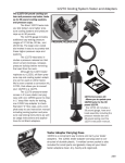
Technical Bulletin
Bulletin No.: PRO-03-10
Subject: Service
Effective Date: 6/13/77
Page: 1 of 7
Line Protection System (SP-1)
Ref: Attachment (6 pgs.)
Bendix HVSG developed a new tractor-trailer protection system, which not only retains
all of the efficiency of the present system, but also provides the capability of applying the
trailer spring brakes when the trailer service line has failed. This added braking ability is
achieved through the use of a new valve, the SP-1 Service Line Protection Valve, in a
standard tractor-trailer protection system. The driver is not required to reach for any
additional controls to activate this unique automatic braking feature. A self-action
decision to apply the trailer spring brakes is resolved by the pneumatic analysis
performed within this new valve.
With each brake valve application, the service line protection valve makes an
instantaneous pneumatic comparison to determine if the trailer service line has failed. If
a failure is detected, the valve then automatically causes the trailer emergency brakes to
be applied, simultaneously closing off the trailer service air.
This system which utilizes an SP-1, 288428, (see Fig. 1) has been installed on recently
delivered fleets of Mack’s, GMC’s and Peterbilt’s for U.P.S. The valve is usually
mounted at the rear of the cab, adjacent to the TP valve.
A system description and operation is attached with a diagrammatic of the piping
arrangement. Approximately 500 of these units are in the field at the present time.
288428
SP-1
Tractor-Trailer Service Line Protection System
System Description
The service line protection valve is used in conjunction with a standard tractor-trailer
protection system. When a brake valve application is made and the trailer service line is
intact, the system operates in a normal manner. When a brake valve application is
made and the trailer service line has failed, the new system simultaneously vents the
trailer supply line (causing the trailer spring brakes to apply) and also shuts off the
tractor service air to the trailer (preserving the tractor air pressure). A subsequent
release of the trailer spring brakes can be accomplished by releasing the brake valve,
thereby recharging the supply line and releasing the trailer brakes. Five or six repeated
full applications and releases are possible before the system pressure is depleted to a
point where the trailer supply valve (PP-7) trips.
Operation
The typical system is piped as shown in Figure 2. A trailer supply valve, in the “on”
position, allows air pressure to pass through the tractor protection valve to supply the
trailer. Application of sufficient trailer supply air pressure across the tractor protection
valve plunger causes the service inlet valve to open.
A. Normal Operation (With Trailer Service Line Intact):
1. When the brake valve treadle is depressed, service air is delivered through the
double check valve to the tractor service port of the tractor protection valve.
2. The inlet valve, being held open by the force of trailer supply air across the
plunger, allows the service air to continue, through the trailer service port and
service line, to the trailer.
3. During every brake application the service pressure is also being monitored at
two sources.
a. One monitor line (#1) originates at the trailer service port side of the tractor
protection valve and is piped to the top control port (to the topside of piston
Item #1 Fig. 3) of the service line protection valve (a normally open valve).
The pressure of this delivered air is equal to the service air pressure being
transmitted to the trailer.
b. The other monitor line (#2) originates at a brake valve primary delivery port
and is piped to the bottom control port (leading to the underside of piston Item
#2 Fig 3.) of the same service line protection valve.
c. When the brake valve delivers more than 50 psi air pressure, a valve (Item 3
Fig. 3 immediately downstream of the bottom control port) opens and allows
a metered rate of air to flow to the underside of a piston. With its delayed
start (at 50 psi delivery pressure) and its metered rate of air flow, the resulting
immediate pressure of the air (being delivered to the underside of the piston
(Item 1) of the service line protection valve by the #2 monitoring line) is less
than that air pressure which has already been delivered to the topside of the
same piston by the #1 monitoring line.
d. In a relatively short time, full applied service pressure is achieved throughout
the system. Due to the designed area and spring differential advantages
across the piston of the service line protection valve (a normally open valve)
no imbalance of the piston occurs and the valve remains open.
4. When the treadle is released, the trailer service line is exhausted through the
brake valve exhaust (or a quick-release valve, if one is piped in).
a. The #1 monitoring air (on top of the piston) follows this same path to the
exhaust.
b. The #2 monitoring air (under the piston) pneumatically lifts an inlet and
exhaust valve and simultaneously also exhausts its air through the brake
valve to atmosphere.
B. Emergency Operation (With Trailer Service Line Not Intact):
1. A brake valve application is made in the same manner as described above; but
with this difference – the air connection between the tractor protection trailer
service port and the trailer is not intact.
a. The delivery air is exhausting to atmosphere at a rate controlled only by the
pressure, the size of the line and/or break in the line.
b. The full delivery pressure of the air leaving the brake valve is substantially
reduced in pressure as it approaches the break in the service line and
atmosphere.
c. The monitoring lines, previously described, are located so as to best sense a
pressure differential thus created.
2. The air pressure now being delivered to the top of the piston of the service line
protection valve (by the #1 monitoring line), due to the break in the service line,
cannot build up to the same air pressure as is being generated at the brake valve
primary delivery port (the source of air for the #2 monitoring line) and being delivered
to the underside of the piston.
3. The pressure differential (sensed by an imbalance of air load in a stabilized air
pressure comparison) causes the service line protection valve (normally open) to
close off the tractor air pressure supply to the trailer and to exhaust the trailer air
supply through inlet exhaust valve Item 4 Fig. 3. This results in applying the trailer
spring brakes.
4. Removal of the trailer supply air from across the tractor protection valve plunger also
causes the service inlet valve to close. This prevents further service air pressure
from being delivered to atmosphere through the break in the service line.
5. Release of the brake treadle valve will cause the service line protection valve to reset
itself (to normally open) and allow the trailer supply pressure to release the spring
brakes (if air pressure is still at a level where the trailer supply valve (PP-7) has not
tripped). This will permit the driver to pull his vehicle to the side of the road for his
inspection.
Installation
A minimum amount of piping change is required to install the service line protection
valve into an existing tractor protection system.
1. The existing trailer supply line is connected to the supply port of the service line
protection valve and from the delivery port, a line is continued to the tractor
protection supply port.
2. Two new lines are required to monitor the air pressure at the service line protection
valve.
a. One line (Monitor Line #2) connects the brake valve primary delivery port and the
underside of the piston.
b. The other line (Monitor Line #1) connects the topside of the piston to either the
trailer service cavity of the tractor protection valve or to a tee located in the
tractor protection valve trailer service port.
FIGURE 1
TYPICAL DUAL CIRCUIT
FIGURE 2
FIGURE 3